

M
M
AG
AG
AR200U Quick User Manual
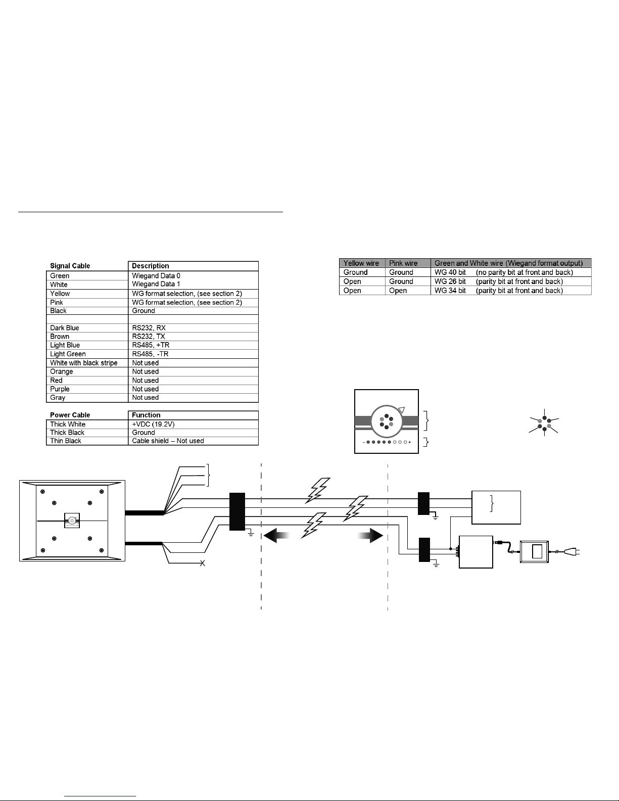
(1) Cable Wire assignment
The AR200U has two main cables: Signal cable and power cable. Cable wiring
description is shown in the tables below:
(2) Interface selection:
Yellow and pink wire is used to select Wiegand output format on Green and White wire.
AR200U’s wiegand output format must match controller’s input format in order to capture
correct card number. Please also ensure that AR200U’s GND is connected to controller’s
GND to achieve “common GND”. Otherwise Wiegand data will not be received by
controller.
(3) LED Indicators
The AR200U has status and tuning LEDs (see figure below).
• Blue LED is on whenever the AR200U is powered and ready to read the card
• Red LED blinks once when the good read has been achieved.
• Green LED is only used during the firmware download.
• Auto tuning LED indicate frequency shift position. The ideal 4 to 5 LED turned
red color.
Access controller
Data 0
Data 1
GND
Wiegand
port
Green
White
Black (GND)
Yellow
Pink
Select Wiegand
output format
Thick Black
Thick White
Signal
Power
Common
GND
PS20A 19.2V
regulator and lter
AC-AC 24V
Power adapter
Main AC
power supply
PD24/7.5
Data and
DC surge
protector
TPLAN
Data surge
protector
PSP24
DC surge
protector
+19.2 V
GND
INSIDE GOOSENECK
(Safely protected by surge protector at end point. All surge protector MUST be connect to EARTH)
CABLE TRAVELING INSIDE PIPING
(Subject to lightning surge induction)
INSIDE GUARD HOUSE
(Safely protected by surge protector at end point. All surge protector MUST be connect to EARTH)
Induced surge will travel both way via
cable to damage device at end point.
AR200U
RFID Mid range reader
Thin Black
Blue
Blue
Red
Red
Green
Green
LED color:
Auto tuning LED
MAGMAG
RFID Reader
Status LED
MAGMAG
RFID Reader
AR200UBKT
Gooseneck
head inside
AR200UBKT
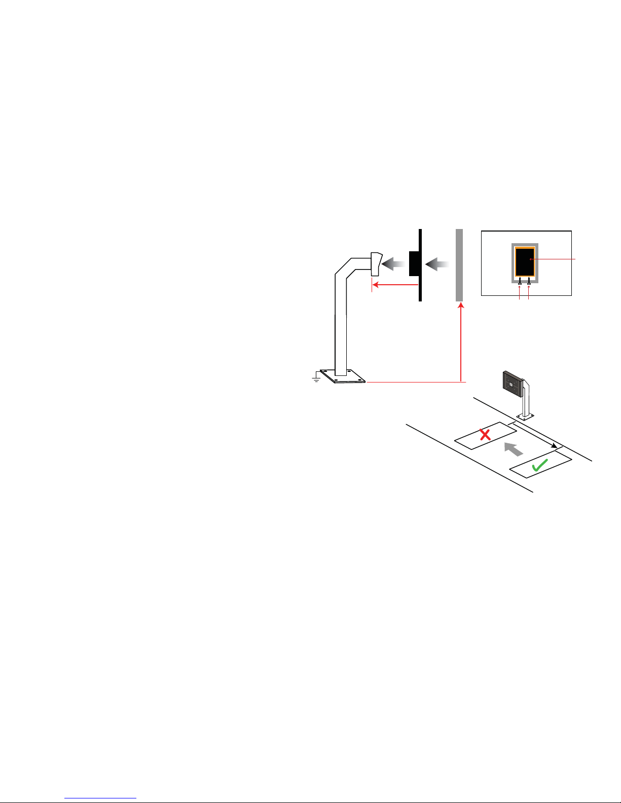
(4) Obtaining the best reading range
(6) Protecting the reader
a) Typically AR200U will be able to achieve 70 to 120cm reading range depending
on the amount of metal/interference presence at site. Reading range experienced
by each vehicle might be different depending on the type of solar film installed on
vehicle side windows.
b) Use original MAG CDS18L mid range RFID card. It containes more internal
copper coil antenna to achieve maximum distance up to 120cm.
c) To achieve maximum range, there shall not be any metal, CRT monitor, any
interference source or another RFID reader within 180 cm of installed AR200U. All
these interfere and inhibit RFID performance.
d) Before installing, first power up AR200U to check the red LED light bar status at
its intended position. Typically a bar of 4 to 5 LED indicates nominal frequency to
achieve RFID full potential range. LED bar with less than 4 or more than 5 bars
indicate frequency shift that will reduce reading range. Please install the AR200U
ONLY after confirming the best position that can achieve longest reading range.
Ensure same numbers of LED are remained after installing AR200U.
e) Do not install loop coil in front of AR200U. The frequency from loop coil will interfere with AR200U reading range. Loop coil has to be at least 130 cm away from
AR200U.
f) AR200U should be installed at a height where entire reader is exposed to the
side glass windows of vehicle. Too low will be blocked by car metal door and
reduce reading range.
g) Please use the orriginal power supply that comes with AR200U. The 2 stage
power supply is designed to output 19.2 V and special filter circuitry to help
AR200U achieve its maximum potential reading range. Using other alternative
power supply might reduce reading range and cause permanent damage to
AR200U.
h) Long distance DC power cabling will experience voltage drop and cause insufficient operation power for AR200U. It is recomended to use 1 or 1.5mm cable thickness for 19.2VDC wiring.
a) AR200U installed outdoor is subject to harsh weather conditioning. Rain water might
enter LED display area creating water vapor trapped inside. It is highly recomended to
protect the reader with AR200HSE, Arylic weatherproof housing.
b) AR200U installed outdoor is also subject to damaged by lightning surge. It is a
compulsory to install data and power surge protector as shown in wiring diagram.
c) Good Earth connection onto the metal gooseneck and all other metal housing will give
extra protection against damage by lightning surge.
AR200U
reader
AR200BKT
arylic bracket
Gooseneck
Keep trying to ash card
and check reading
distance until get best
position L that allowed
maximum reading range.
L
Connect gooseneck body
to EARTH using 1.5 mm
cable
(5) Installing the reader
130 cm
Wrong loop
coil position
Correct loop
coil position
Approximate same
height H as vehicle side
windows frame
Vehicle travel
direction
Secure AR200UBKT to gooseneck head
with self tapping screw from below. Do
NOT drill through into gooseneck head.
H
 Loading...