


QUICK START GUIDE
E210 Series cellular router
Version 1.0

P.1 Maestro E210 Series www.maestro-wireless.com
Copyright
©2017 Maestro Wireless Solutions Limited
All rights reserved
This document is for the use of intended recipients only; content may not be
reproduced, redistributed, or copied in whole or in part for any purpose without prior
consent from Maestro Wireless Solutions Limited.

P.2 Maestro E210 Series www.maestro-wireless.com
Terms and Conditions
Content of this document is subject to change without notice and is written without
warranty.
Maestro Wireless Solutions Limited reserves the right to modify and to improve
the product and all related accessories without prior notice.
Performance of the product and its accessories depends on the method of usage and
operating environment.
Maestro Wireless Solutions Limited assumes no liability for any damage incurred
directly or indirectly from errors, omissions or discrepancies between the router and
this document.
No warranty whether expressed or implied is given by Maestro Wireless Solutions
Limited in relation to any software, solution or application. User shall assume the
entire risk of using or relying on this software, solution, and application, and, Maestro
Wireless Solutions Limited takes no responsibility for, and will not be liable for, the
product or any related software being temporarily unavailable due to any technical
issue occurred in any event.
In no event, Maestro Wireless Solutions Limited will be liable for any loss,
damage, indirect or consequential loss or any loss arising from loss of data or profit
arising out of, or in connection with, the use of this router product.
The above terms and conditions are subject to change without prior notice. The
present use of this product solution implies that the user approves and understands
all the above terms and conditions.

P.3 Maestro E210 Series www.maestro-wireless.com
This E210 series quick start guide applies to below models:
• E213
• E214#02
• E214#358S#158
• E214#078
• E214G#01
• E214G#00
• E215#02
• E218#1JL
• E218#1BI
• E218#04

P.4 Maestro E210 Series www.maestro-wireless.com
Table of Content
1 Safety precautions
1.1 General precautions 5
1.1 Using the router in vehicle 5
1.2 Protecting your router 5
2 Overview
2.1 Scope 6
2.2 Target audience 6
3 E210 series compatible models 7
4 Product overview
4.1 General specification 8
4.2 Back panel connection 8
4.3 Front panel connection 9
5 E210 cable and accessory 10
6 Status LED Indicator 11
7 Setup
7.1 Prerequisite 12
7.2 Connecting the E210 router 13
7.3 Software configuration 16
8 Compatible Antenna 19

P.5 Maestro E210 Series www.maestro-wireless.com
1 Safety Precautions
1.1 General precautions
The router generates radio frequency (RF) power. When using the router,
care must be taken to ensure safety as well as compliance with all the
regulations that surround the use of RF equipment.
Do not use the router in aircraft, hospitals and petrol stations or in places
where using GSM, W-CDMA and LTE equipment or any other RF equipment
is prohibited, and make sure that the router is not interfering with nearby
equipment such as pacemakers or medical equipment.
All antennae of the router should be directed away from computers, office
equipment, home appliances, etc., and always keep the router at a minimally
safe distance of 26.6cm or more from human bodies.
Do not put the antenna inside metallic boxes or other containers.
1.2 Using the router in vehicles
Check for regulations/law, if any, for authorising the use of GSM, W-CDMA
and LTE equipment in vehicles in your country before installing the router.
Installation of the router should be done by qualified personnel. Consult your
vehicle dealer for any possible interference concerns to the use of the router.
Battery of the vehicle could be drained after an extended period when the
router is powered by the vehicles main battery.
1.3 Protecting your router
Please install and operate the router with care, and complying the following;
Do not expose the router in extreme conditions such as high humidity/rain,
high temperature, direct sunlight, caustic/harsh chemicals, dust, or water.
Do not try to disassemble or modify the router as there is no user serviceable
parts inside and the warranty would be voided in the case of tampering.
Do not drop, hit, shake the router in extreme vibrations.
Do not pull the power supply cable. Please attach or detach it by holding the
connector after switching off the supply.
Install and connect the router in accordance with this document.
Failure to do so will void the warranty.

P.6 Maestro E210 Series www.maestro-wireless.com
2 Overview
2.1 Scope
This document provides you all the information needed to setup, to configure
and to use the Maestro E210 series cellular router.
2.2 Target audience
This document is intended for end-users or resellers who understand basic
telecommunications and information technology terminologies and concepts.

P.7 Maestro E210 Series www.maestro-wireless.com
3 E210 series compatible models
Please consult us regarding the models or features shown in grey, which are subject to MOQ and other considerations.
1
U plink / Downlink maximum data rates
2
R anked by increasing frequencies
3
Besides MIL-STD-810G
- 2G:
λ1 85.6
/ 236.8; or 236.8 / λ2236.8; or λ3296 kbps
a
Also North America’s B17 subset
4
F irst customer shipment [date of]
- NB-IoT: 65 / 27 kbps
b
Also KDDI’s B18 and North America’s B5 subsets,
5
Also EN 60950-1
- LTE-M1: 375 / 300 kbps
the latter containing NTT DoCoMo's B19 subset,
6
Also Class I Division 2 for use in explosive atmospheres
- LTE cat. 1: 5 / 10 Mbps (FDD); 3.1 / 8
.96
Mbps (TDD)
itself containing Japan’s B6 subset
as a factory option subject to MOQ and other considerations
- 3G: 5
.76
/
ζ1 7.2
; or
ζ2 10.1
; or
ζ3 42.2
Mbps
c
Also Japan’s B9 subset
- LTE cat. 4: 50 / 150 Mbps (FDD); 35 / 130 Mbps (TDD)
d
In fact, the 2535 MHz ~ 2655 MHz subset of B41
07 August 2018

P.8 Maestro E210 Series www.maestro-wireless.com
4 Product overview
4.1 General specification
Casing: Brushed Aluminum
Dimensions: 92x57x22(mm)
Weight: 150g (approx.)
Operating temperature: -20°C ~ +60°C; up to 95% R.H.
Storage temperature: -40°C ~ +85°C; up to 95% R.H.
Flash memory (SPI): 32MB
RAM (DDR2 SD-RAM): 128MB
Ethernet LAN & WAN: 10/100BASE-T
Wi-Fi: IEEE 802.11b/g//n 2.4GHz
GPS: IZatTM gen. 8C gpsOne
4.2 Back panel connection
Black – Wi-Fi antenna, RP-SMA connector
Red – Cellular diversity antenna, SMA connector
Green – GPS antenna, SMA connector
Yellow – Cellular main antenna, SMA connector
Purple – MicroSD-XC card slot
Blue – Dual SIM slots: Left: SIM 2; Right: SIM 1

P.9 Maestro E210 Series www.maestro-wireless.com
4.3 Front panel connection
Green – D.C. Power: 4-pin Micro-fit 3.0 connector
Top L/R: 8V~32V dc
Bottom L/R: Two digital I/Os
Digital Input: 0~1V dc as low
1~36V dc as high
Digital Output: Open collector,
100mA@24V dc max
Black – Reset button: Back to default settings (push for 10sec)
Red – RS-232:
1. DCD
2. Rx
3. Tx
4. DTR
5. Ground
6. DSR
7. RTS
8. CTS
9. RI
Blue – Ethernet ports: Left: LAN
Right: WAN or set as 2nd LAN

P.10 Maestro E210 Series www.maestro-wireless.com
5 E210 series cable and accessory
Item
Description
Power supply/Cable
ACC-CA10
4-pin Micro-Fit 3.0(M) to stripped wire with 2.5A fused, 1 meter long cable
ACC-PS20-F
4-pin Molex 1.2A power adapter with Euro plug 2-pin - Europe
ACC-PS21-F
4-pin Molex 1.2A power adapter with NEMA 2-pin plug - America
ACC-PS22-F
4-pin Molex 1.2A power adapter with AS3112 3-pin plug - Australia/NZ
ACC-PS23-F
4-pin Molex 1.2A power adapter with BS1363 3-pin plug - UK
Wi-Fi Antenna
ACC-A21
5-band 2.4/5.8GHz antenna, hinged RP-SMA (M)
Cellular / GPS Antenna
ACC-A11 or
A17A
5-band 850/900/1800/1900/2100MHz magnetic mount antenna, 3 meter
cable, SMA(M)
ACC-A03
GPS 1575.42MHz Magnetic mount antenna, 3 meter cable, SMA(M)
ACC-A22
Ultra-wideband 698-960/1575.42/1710-2700MHz L-shaped antenna,
hinged, SMA(M)
Miscellaneous
ACC-DIN
Metal dual mount DIN Rail clip
ACC-CA29
RJ45(M) to RJ45(M), 1 meter cable length

P.11 Maestro E210 Series www.maestro-wireless.com
6 Status LED Indicator
The E210 operation status is indicated by six LEDs as shown above, and described
in the below table;
Name
Color and Status
Description
Wi-Fi
OFF
Wi-Fi network is inactive
Blue ON
Wi-Fi network is activated
Blue Flashing
Wi-Fi network data transferring
Activity
OFF
Cellular data service is not connected
Amber ON
Cellular data service is connected
Amber Flashing
Cellular data transferring
Network
OFF
Not registered on cellular network
Amber ON
Registered on cellular network (home)
Amber Flashing
Registered on cellular network (roaming)
Signal
OFF
No signal (CSQ=0 to 5, 97, 98, 99)
Amber Flashing
Weak signal (CSQ ≤ 12)
Amber ON
Strong signal (CSQ ≥ 12)
Power
OFF
Power off
Green ON
Power on
Alert
OFF
No alert
Red Flashing
Precaution (i.e. SIM not inserted, LAN not connected)
Red ON
Hardware fault (i.e. overheated, memory corruption)

P.12 Maestro E210 Series www.maestro-wireless.com
7 Setup
7.1 Prerequisite
Prior to the E210 series router setup:
Activated SIM card
Ethernet cable
Wi-Fi and cellular antenna
Ethernet port or Wi-Fi connectivity with Internet service
Web browser; Internet Explorer 8+, Google Chrome, Mozilla Firefox
or Safari for accessing the Maestro Web Admin Console
DHCP set to enable
Enabling DHCP on Windows:
Start menu Control Panel Network and Internet
Network and Sharing Center Change adapter settings
Right click on Local Area Connection Internet Protocol
Version 4(TCP/IPv4)
Properties
Obtain an IP address automatically & Obtain DNS server
address automatically
Enabling DHCP on MAC OS:
Launch System Preferences, then choose Network.
Select Ethernet from the adapters list on the left.
Set the Configure IPv4 drop-down to Using DHCP
P.13 Maestro E210 Series www.maestro-wireless.com
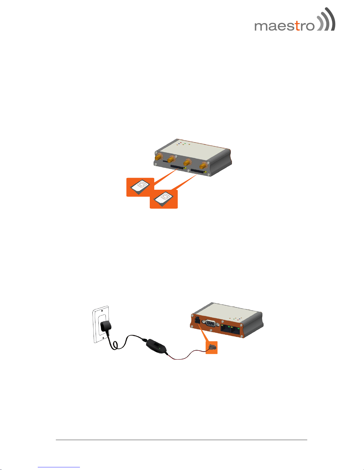
7.2 Connecting the E210 router
Inserting SIM cards
Eject the SIM tray by pushing the yellow SIM tray eject button inwards, take
the SIM tray out from the slot, place the mini-SIM card with SIM chip facing
up, and insert the tray back in place carefully.
Connecting the AC power
Connect the A.C. power cord as shown below, or you can refer to Section 4.3
in Green, D.C. Power.

P.14 Maestro E210 Series www.maestro-wireless.com
Antenna connection
Main
Series
Auxiliary
Picture
Cellular
only
E213
E215
N/A
E214
E218
Cellular
only
E214G
GPS and
cellular
Note: Dual cellular antennae improve data throughput/performance on
cellular data transfer rate.
Cellular antenna selections base on frequency bands of cellular networks in
individual countries, refer to Section 3, E210 series compatible models and
Section 8, Compatible Antenna, or contact Maestro technical support
https://support.maestro-wireless.com
P.15 Maestro E210 Series www.maestro-wireless.com
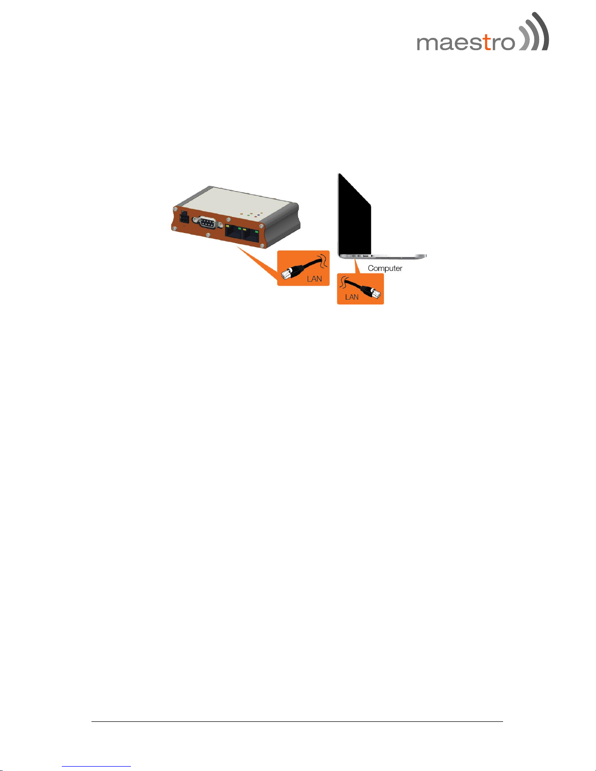
Connecting the router to a computer
Connect an Ethernet cable between the LAN port of the Maestro router and a
computer as shown below, or refer to section 4.2 in Blue, Ethernet ports.

P.16 Maestro E210 Series www.maestro-wireless.com
7.3 Software Configuration
Open a web browser, use the below default LAN IP address;
Parameters
Details
IP Address (LAN)
192.168.1.1
Username
admin
Password
admin
Note: Username and password are both case sensitive.
Enter the above default login credentials when the below appears on the web
browser;
Click Quick Setup as shown below to bring the Network Setup page;

P.17 Maestro E210 Series www.maestro-wireless.com
Network Setup page;
If default settings need to be changed, settings can be manually configured
for LAN, WAN, Cellular and Wi-Fi, then you can click Save & Apply to store
the configuration.
In Cellular, all fields depend on SIM cards provider/cellular network
operator, enquire with them for authentication credentials, if needed.

P.18 Maestro E210 Series www.maestro-wireless.com
After all of above procedures, cellular connection should be established in
about one minute time with adequate signal reception (if the default setting is
used).
To see the status of the cellular connection, from the pull-down menu at the
top, click Status and scroll down to Cellular as shown below;

P.19 Maestro E210 Series www.maestro-wireless.com
8 Compatible Antenna
Wi-Fi antenna
5dBi gain
Peak gain: 3.8dBi@2.4GHz ~2.5GHz
RP-SMA(M), hinged
RoHS Compliant
WWAN antenna
2dBi gain (minimum)
Operating frequency in the used LTE bands
SMA, hinged
RoHS Compliant

P.20 Maestro E210 Series www.maestro-wireless.com
For further support on Maestro products, please visit Maestro support website,
http://support.maestro-wireless.com/
 Loading...