

Maestro MAELV-600, MSCELV-600M User Manual
Lutron Electronics Co., Inc.
7200 Suter Road
Coopersburg, PA18036-1299, U.S.A.
Made and printed in the U.S.A. 11/03 P/N 030-735 Rev. B
Operation
Limited Warranty
Lutron will, at its option, repair or replace any unit that is defective in materials or manufacture within one year after
purchase. For warranty service, return unit to place of purchase or mail to Lutron at 7200 Suter Rd., Coopersburg, PA
18036-1299, postage pre-paid.
THIS WARRANTY IS IN LIEU OF ALL OTHER EXPRESS WARRANTIES, AND THE IMPLIED WARRANTY OF
MERCHANTABILITY IS LIMITED TO ONE YEAR FROM PURCHASE. THIS WARRANTYDOES NOT COVER THE
COST OF INSTALLATION, REMOVAL OR REINSTALLATION, OR DAMAGE RESULTING FROM MISUSE, ABUSE,
OR DAMAGE FROM IMPROPER WIRING OR INSTALLATION. THIS WARRANTY DOES NOT COVER INCIDENTALOR CONSEQUENTIAL DAMAGES. LUTRON’S LIABILITY ON ANY CLAIM FOR DAMAGES ARISING OUT OF
OR IN CONNECTION WITH THE MANUFACTURE, SALE, INSTALLATION, DELIVERY, OR USE OF THE UNIT
SHALL NEVER EXCEED THE PURCHASE PRICE OF THE UNIT.
This warranty gives you specific legal rights, and you may have other rights which vary from state to state. Some states
do not allow the exclusion or limitation of incidental or consequential damages, or limitation on how long an implied
warranty may last, so the above limitations may not apply to you.
This product is covered under one or more of the following U.S. patents: 4,835,343; 5,248,919; 5,399,940; 5,510,679;
5,637,930; 5,798,581; DES 353,798 and corresponding foreign patents. U.S. and foreign patents pending. Lutron,
Claro, and Maestro are registered trademarks and FASS is a trademark of Lutron Electronics Co., Inc. NEC is a registered trademark of the National Fire Protection Association, Quincy, Massachusetts.
© 2003 Lutron Electronics Co., Inc.
Technical Assistance
If you have questions concerning the installation or operation of this product, call the Lutron Technical
Support Center. Please provide exact model number when calling. (800) 523-9466 (U.S.A., Canada, and
the Caribbean)
Other countries call (610) 282-3800
Fax (610) 282-3090
Internet: www.lutron.com
email: product@lutron.com
®
Electronic Low Voltage Dimmer
MAELV-600, MSCELV-600M
(600 W maximum, 5 W minimum) 120 V , 60 Hz
Smart Remote
MA-R, MSC-AD
(8.3 A maximum) 120 V , 60 Hz
Important Notes
1. Caution: To avoid overheating and possible damage to other equipment,
do not use to control receptacles, fluorescent lighting fixtures, motor-operated or transformer-supplied appliances.
2. Install in accordance with all national and local electrical codes.
3. When no “grounding means” exist within the wallbox then the NEC®
2002, Article 404-9 allows a dimmer without a grounding connection to
be installed as a replacement, as long as a plastic, noncombustible
wallplate is used. For this type of installation, cap or remove the green
ground wire on the dimmer and use an appropriate wallplate such as
Lutron's Claro
® series wallplates.
4. Do not paint Dimmers or Smart Remotes (MA-R, MSC-AD).
5. Use to control the primary side of electronic transformer-supplied low-
voltage lighting, incandescent lamps, or a combination of the two.
6. Some fixture manufacturers do not recommend dimming their solid-state
transformers. To determine if a fixture can be dimmed, consult the fixture
manufacturer.
7. This product requires a neutral wire in the wallbox. If a neutral wire is not
present, contact a licensed electrician for installation.
8. This control is overload protected. If the rated wattage is exceeded,
power to the circuit will shut off until the control cools. It this occurs,
remove excess load from the circuit.
9. Maestro® Dimmers are not compatible with standard 3-way switches, for
use only with Smart Remotes (MA-R, MSC-AD).
10. Smart Remotes (MA-R, MSC-AD) can not be used individually but must
be used in conjunction with a Maestro
® Dimmer in a 3-way/4-way applica-
tion.
11. Only one Maestro® Dimmer can be used in a multi-location circuit with up
to nine Smart Remotes (MA-R, MSC-AD). The Smart Remotes (MA-R,
MSC-AD) must be wired on the line side of the Dimmer.
12. In multi-phase applications, use a separate neutral for each phase containing a dimmed circuit.
13. Operate between 0°C (32° F) and 40°C (104° F).
14. Dimmer may feel warm to the touch during normal operation.
15. Recommended wallbox depth is 2 1/2" (64 mm) minimum.
16. Maximum wire length between the Dimmer and the last Smart Remote
(MA-R, MSC-AD) is 300 feet (91 m).
17. Clean with a soft damp cloth only. Do not use any chemical cleaners.
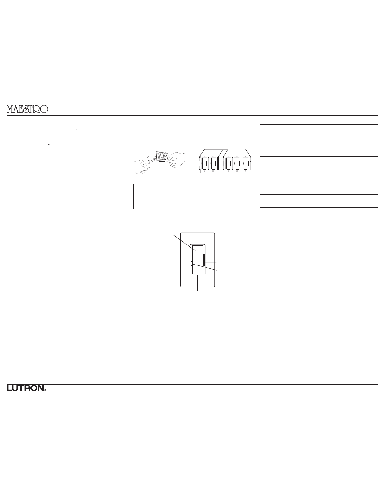
Multigang Installations
When combining controls in the same wallbox, remove all inner side sections
prior to wiring (see below). Using pliers, bend side sections up and down until
they break off. Repeat for each side section to be removed. Reduction of
Dimmer capacity is also required. Refer to chart below for maximum Dimmer
capacity.
Breaking Side
Sections
IMPORTANT NOTICE:
FASSTM - Front Accessible Service Switch - to replace
bulb, power may be conveniently removed by sliding
FASS switch to the left, on both the Dimmer and any
Smart Remotes.
For any procedure other than routine
lamp replacement, power must be disconnected at
the main electrical panel.
Dimming Rocker
Press to brighten
Press to dim
LED light level
indicators
Tap Switch Options
• Tap once - Lights adjust
smoothly to level set by rocker.
•
Tap twice quickly - Lights adjust
rapidly to full.
•
Tap again - Lights adjust
smoothly to off.
• Fade to OFF - Press and hold to
activate delayed fade to OFF. As
tap switch is held the bottom
LED will begin to flash indicating
a 10 second fade to off. Each
subsequently flashing LED represents 10 seconds of delay
before dimmer fades to OFF (up
to 60 seconds).
• Locked-in Preset - Tap 4 times
quickly to set the current light
level as the “Locked-in”preset
(the LEDs will blink twice indicating the preset was locked). When
the dimmer is turned ON via this
button it will always go to this
“Locked-in” light level rather than
the previous light level.To unlock
the preset, tap the switch 4 times
quickly (the LEDs will blink three
times indicating the preset was
unlocked).
Troubleshooting
No Sides
Removed
600W
1 Side
Removed
500W
Sides Removed
2 Sides
Removed
400W
Type of
Smart Dimmer
Electronic Low-voltage
600W
Symptom
Light does not turn on.
Lamps flicker with low-voltage loads.
LEDs do not turn OFF when
FASSTM switch on the dimmer is in the OFF position
(to the left).
Lights cycle OFF and ON.
Dimmer does not respond
properly to a Smart
Remote.
Possible Cause
• Front Accessible Service Switch (FASSTM) on the
Dimmer or Smart Remote is switched to the left
(See Step 5).
• Light bulb(s) burned out.
• Breaker is off or tripped.
• Dimmer not wired correctly.
• Neutral not wired to Dimmer (white wire).
• Wrong load type used. Verify that load is electronic
low-voltage.
• The yellow and black wires are reversed. See wiring
diagram in Step 5 for correct wiring.
• Overload protection circuit active – remove excess
load to correct.
• Smart Remote is not on the line side of the Dimmer.
Do Not Remove
Outside Sections
Each Control Has Inside
Section Removed
Middle Control Has Two Side
Sections Removed
Ground
Black
Yellow
Tag
Note wire color
Dimmer
Green
White
Green
Ground
Red
Blue
Tag
Black
Smart
Remote
Single-Location control
Multi-Location control or more
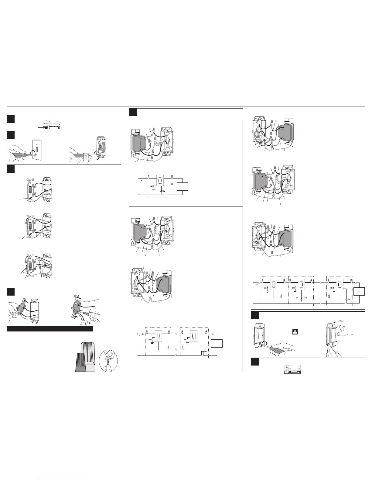
Installation
For installations involving more than one control in a wallbox, refer to Multigang Installations before
beginning.
Turn screws
to loosen.
Tag
Note: Screw
placement may
be different on
your switch.
Same colored
screw (or
marked IN or
OUT)
Ground
(Bare Copper or
Green Wire)
Single-Location control
Two-Location control
Multi-Location control
Ground
(Bare Copper
or Green Wire)
Tag
Screw Terminals:
Turn screws to
loosen.
One switch controlling a light fixture.
This switch will be a single-pole.The switch will have
insulated wires connected to two screws of the same
color plus a green ground screw.
Three switches controlling a light fixture.
Two switches will be 3-way and others will be 4-way.TAG
the two 3-way switches as in the Two-Location diagram
above.The 4-way switch will have four screws plus a
green ground screw.TA G the two same color insulated
wires which are connected to opposite colored screws.
Two switches controlling a light fixture.
Both switches will be 3-way. Each switch will have three
screws plus a green ground screw.One of these is a
screw of a different color (not green) or labeled COMMON. TAG this wire on both switches to identify when
wiring.
Ground
(Bare Copper or
Green Wire)
Different-colored
screw (Common)
Ground
Green
Dimmer
Black
ON
OFF
ON
OFF
ON
OFF
NOTE: Only one MAELV-600 or MSCELV-600M can
be used per multi-location circuit. The Smart
Remote(s) (MA-R, MSC-AD) must be wired on the
line side of the dimmer.
ON
OFF
ON
OFF
ON
OFF
Yellow
Blue
Start screws.
Align dimmer and
tighten screws.
Caution: Do not
overtighten mounting screws.
Important Wiring Information
Twist wire connector tight.
Be sure no bare wire is
exposed.
When making wire connections, follow the recommended strip lengths and combinations for the supplied wire connectors.
Note: Wire connectors provided are suitable for copper wire only.For aluminum wire, consult an electrician.
Small
Large
Small:
Strip insulation 3/8" (10 mm) for 14 AWG wire
Strip insulation 1/2” (13 mm) for 16 or 18 AWG wire
Use to join one 14 AWG supply wire with one 16 or 18 AWG
control wire.
Large:
Strip insulation 1/2" (13 mm) for 10, 12 or 14 AWG wire
Strip insulation 5/8" (16 mm) for 16 or 18 AWG wire
Use to join one or two 12 or 14 AWG supply wires with one 10,
12, 14, 16, or 18 AWG control wire.
Two-Location control
Wiring the Dimmer:
• Connect the green wire on the dimmer to the bare copper
or green ground wire in the wallbox.
• Connect the yellow wire on the dimmer to the wire going
to the lighting load.
• Connect the black wire on the dimmer to the other wire
removed from the switch.
• Connect the white wire on the dimmer to neutral.
• Cap off the blue wire on the dimmer. It is not used in a sin-
gle-pole circuit.
Wiring the Dimmer:
• Connect the green wire on the dimmer to the bare copper
or green ground wire in the wallbox.
• Connect the yellow wire on the dimmer to the tagged wire
removed from the switch.This wire must be going to the
lighting load.
• Connect the black wire on the dimmer to either of the
remaining wires removed from the switch.
• Connect the white wire on the dimmer to neutral.
• Connect the blue wire on the dimmer to the remaining wire
removed from the switch (note wire color).
Wiring the Smart Remote (MA-R, MSC-AD):
• Connect the green wire on the Smart Remote to the bare
copper or green ground wire in the wallbox.
• Connect the red wire on the Smart Remote to the tagged
wire removed from the switch.
• Connect the blue wire on the Smart Remote to the same
color wire that was connected to the blue wire on the dimmer noted above.
• Connect the black wire on the Smart Remote to the
remaining wire removed from the switch.
Wiring the Dimmer: (replaces a 3-way switch)
Note:The Dimmer MUST be on the load side of the Smart
Remotes.
• Connect the green wire on the dimmer to the bare copper
or green ground wire in the wallbox.
• Connect the yellow wire on the dimmer to the tagged wire
removed from the switch.This wire must be going to the
lighting load.
• Connect the
blue wire on the dimmer to the same color
wire that was connected to the
blue wire on the Smart
Remote noted above.
• Connect the black wire on the dimmer to the remaining
wire removed from the switch.
• Connect the white wire on the dimmer to neutral.
Wiring a Smart Remote (MA-R, MSC-AD):
(replaces the 4-way switch(es))
• Connect the green wire on the Smart Remote to the bare
copper or green ground wire in the wallbox.
• Connect the blue wire on the Smart Remote to both of the
tagged wires (noting their color) removed from the 4-way
switch.
• Connect the black wire on the Smart Remote to one of the
remaining wires removed from the switch.
• Connect the red wire on the Smart Remote to the remain-
ing wire removed from the switch.
Wiring another Smart Remote (MA-R, MSC-AD): (replaces
a 3-way switch)
• Connect the green wire on the Smart Remote to the bare
copper or green ground wire in the wallbox.
• Connect the black wire on the Smart Remote to the tagged
wire removed from the switch.
• Connect the blue wire on the Smart Remote to the same
color wire that was connected to the blue wire on the dimmer noted above.
• Connect the red wire on the Smart Remote to the remain-
ing wire removed from the switch.
Connect up to
a total of 9
Smart
Remotes.
White
Dimmer
Ground
Hot
120 V
60 Hz
Electronic
Low-voltage
Load
Neutral
Wallbox
White
Blue
Yellow
Green
Black
Ground
Green
Tag
Black
Blue
Red
Smart
Remote
NOTE: Only one MAELV-600 or MSCELV-600M can
be used per multi-location circuit. The Smart
Remote(s) (MA-R, MSC-AD) must be wired on the
line side of the dimmer.
Green
Ground
Red
Blue
Tag
Black
Smart
Remote
Ground
Black
Blue
Yellow
Tag
Note wire color
Dimmer
Green
White
Backwired:
Insert screwdriver.
Pull wire out.
1
WARNING: Turn power OFF at circuit breaker (or remove fuse).
Remove switch mounting screws. Pull switch from wall.
2
Identify type of circuit:
3
Disconnect switch wires.
4
Wiring the controls:
NOTE: Actual wire locations on Dimmer and Smart Remotes may vary from illustrations.
5
Blue
Turn power ON at circuit breaker (or replace fuse).
7
Mount and align Dimmer (and Smart Remote). Install wallplate(s).
6
Smart Remote Dimmer
Ground
Hot
120 V
60 Hz
Electronic
Low-voltage
Load
Neutral
Wallbox Wallbox
Blue
Black
Green
Red
Ground
White
Blue
Yellow
Green
Black
Smart Remote Smart Remote Dimmer
Ground
Hot
120 V
60 Hz
Electronic
Low-voltage
Load
Neutral
WallboxWallboxWallbox
Blue
Black
Green
Red
Ground
Blue
Black
Green
Red
Ground
White
Blue
Yellow
Green
Black
 Loading...