

Maestro M1002G, M1003G485, M100CDMAplus, M100CDMA485, M1003G User Manual
MAESTRO M100 SERIES
SMARTPACK USER MANUAL
VERSION 5
FOR APPLICATION VERSION 2.2.3
ON
M1002G, M1003G, M1003G485,
M100CDMAPLUS, M100CDMA485
WW W.MAESTR O-WIRELESS.CO M
EM AIL: SUP PORT@MA ES TRO-WIRELES S.COM
TE L: (+852) 2869 0688
FAX: (+852) 2525 4701
AD DRESS: 9/F, 121 KIN G LAM ST RE ET, CHEUNG SHA WAN , HON G KONG

2 Confidential, the whole document is the sole property of Maestro Wireless Solutions ltd.
support@maestro-wireless.com

Revision history
Version
1
2
3
4
Date
13 May 2013 First Issue Samuel Chéreau
Add details on M100 3G GPS commands on
Chapter 23
Correct input command string details in section
22 Jul 2013
26 Feb 2014
2 March 2016
21.4
Edited pictures for GPIO connections
Add details on IOBR, IOBW commands
Typo
Update for 097g
Added command to switch from WipSoft and
SmartPack
Added command to reset all SmartPack settings to
default
Added debug command for TCP/IP stack
Update for version 2.2:
Added Chapter 18 for serial to IP mode
Fixed IP section (21.4)
Edited AUFCM and IPBUFF description to clarify its
application
10 Command string CT service can be used
Edited IPPING as it supports URL address
Corrected CT description in 22.1
SMSAT can accept any ASCII character
Edited IPOPT=1 parameter description
Added a note for TMODE input voltage
Edited IPTCP and IPUDP with <UART> parameter
description
Edited GP 1 service description
Fixed IPPING <echo_time> response
Edited AUOPT to add option 4, 5 and 6
Clarified GPSSTART default values
Edited IPOPT=5 parameter description
Edited OTCP/OUDP note
Deprecated "Keep Alive"
Added GPS command string example
Details
Originated by
Samuel Chéreau
Samuel Chéreau
Samuel Chéreau
Update for version 2.2.3:
Clarified SMSAT SMS deletion limit,
Add TR to command string service for SMS,
Socket, Email, and Output
Fix command string Socket details typo,
Add +CSPN command to handle phone number for
SMS command string if SIM card phonebook is
5
7th June 2018
Confidential, the whole document is the sole property of Maestro Wireless Solutions ltd.
locked,
Added note on +IPPING for server not found error
code,
Edited response parameters of +IPDDNSUPD,
Added +LED to force switch off of the led for power
saving,
Updated known issues and changelog.
support@maestro-wireless.com
Samuel Chéreau
3

This manual is written without any warranty.
Maestro Wireless Solutions Ltd. reserves the right to modify or improve the product and its accessories which can
also be withdrawn without prior notice.
Besides, our company stresses the fact that the performance of the product as well as accessories depends not only
on the proper conditions of use, but also on the environment around the places of use.
Maestro Wireless Solutions Ltd. assumes no liability for damage incurred directly or indirectly from errors, omissions or discrepancies between the modem and the manual.
This software, solution or application is provided on an "as is" basis. No warranty whether expressed or implied is
given by Maestro Wireless Solutions Ltd. in relation to this software, solution or application. User shall assume
the entire risk of using or relying on this software, solution or application.
In no event will Maestro Wireless Solutions Ltd. be liable for any loss or damage including without limitation,
indirect or consequential loss, damage, or any loss, damage whatsoever arising from loss of data or profit arising out
of, or in connection with, the use of this software, application or solution.
Every effort is made to keep the software, application or solution up and running smoothly. However, Maestro
Wireless Solutions Ltd. takes no responsibility for, and will not be liable for, the software, application or solution
being temporarily unavailable due to technical issues beyond our control.
The above terms and conditions are subject to change without prior notice. The present use of this software, application or solution implies the user approves and understands all the above terms and conditions.
4 Confidential, the whole document is the sole property of Maestro Wireless Solutions ltd.
support@maestro-wireless.com

Contents
1 Introduction 11
1.1 SmartPack version command . . . . . . . . . . . . . . . . . . . . . . . . . . . . . . . . . . . . . . . . . 12
1.2 Erasing the SmartPack application . . . . . . . . . . . . . . . . . . . . . . . . . . . . . . . . . . . . . . 12
1.3 Switch between WipSoft and SmartPack . . . . . . . . . . . . . . . . . . . . . . . . . . . . . . . . . . . 13
1.4 Reset SmartPack settings to default value . . . . . . . . . . . . . . . . . . . . . . . . . . . . . . . . . . 13
1.5 Debug command for IP communication . . . . . . . . . . . . . . . . . . . . . . . . . . . . . . . . . . . 14
1.6 Change serial port configuration from the USB . . . . . . . . . . . . . . . . . . . . . . . . . . . . . . . 14
1.7 Force device LED to be off . . . . . . . . . . . . . . . . . . . . . . . . . . . . . . . . . . . . . . . . . . 15
2 Cellular and TCP/UDP parameters setup 17
2.1 CellularNetwork Parameters . . . . . . . . . . . . . . . . . . . . . . . . . . . . . . . . . . . . . . . . . . 17
2.1.1 Cellular network parameters . . . . . . . . . . . . . . . . . . . . . . . . . . . . . . . . . . . . . 17
2.1.2 Activating cellular connection . . . . . . . . . . . . . . . . . . . . . . . . . . . . . . . . . . . . . 18
2.2 TCP/UDP Parameters Setup . . . . . . . . . . . . . . . . . . . . . . . . . . . . . . . . . . . . . . . . . 19
2.2.1 TCP socket parameters . . . . . . . . . . . . . . . . . . . . . . . . . . . . . . . . . . . . . . . . 19
2.2.2 UDP socket parameters . . . . . . . . . . . . . . . . . . . . . . . . . . . . . . . . . . . . . . . . 20
2.2.3 Socket buffer parameters . . . . . . . . . . . . . . . . . . . . . . . . . . . . . . . . . . . . . . . 21
2.3 Extra TCP/UDP Parameters Setup . . . . . . . . . . . . . . . . . . . . . . . . . . . . . . . . . . . . . . 22
3 Automatic and self-recovery TCP/UDP connection 25
3.1 Flow diagram of Auto TCP/UDP connection function . . . . . . . . . . . . . . . . . . . . . . . . . . . . 26
3.2 AT commands for Auto TCP/UDP connection . . . . . . . . . . . . . . . . . . . . . . . . . . . . . . . . 27
3.2.1 Automatic TCP connection . . . . . . . . . . . . . . . . . . . . . . . . . . . . . . . . . . . . . . 27
3.2.2 Automatic UDP connection . . . . . . . . . . . . . . . . . . . . . . . . . . . . . . . . . . . . . . 28
3.2.3 Buffering time . . . . . . . . . . . . . . . . . . . . . . . . . . . . . . . . . . . . . . . . . . . . . . 29
3.2.4 Optional parameters . . . . . . . . . . . . . . . . . . . . . . . . . . . . . . . . . . . . . . . . . . 30
4 AT command driven TCP/UDP connection 33
4.1 Closing connection command . . . . . . . . . . . . . . . . . . . . . . . . . . . . . . . . . . . . . . . . . 33
4.2 Opening TCP connection . . . . . . . . . . . . . . . . . . . . . . . . . . . . . . . . . . . . . . . . . . . 34
4.3 Opening UDP connection . . . . . . . . . . . . . . . . . . . . . . . . . . . . . . . . . . . . . . . . . . . 34
5 Ping service 37
Confidential, the whole document is the sole property of Maestro Wireless Solutions ltd.
support@maestro-wireless.com
5

5.1 Setting up and executing ping command . . . . . . . . . . . . . . . . . . . . . . . . . . . . . . . . . . . 37
6 Dynamic DNS 39
6.1 Description of operation . . . . . . . . . . . . . . . . . . . . . . . . . . . . . . . . . . . . . . . . . . . . 39
6.2 Dynamic DNS server . . . . . . . . . . . . . . . . . . . . . . . . . . . . . . . . . . . . . . . . . . . . . . 40
6.3 Dynamic DNS account . . . . . . . . . . . . . . . . . . . . . . . . . . . . . . . . . . . . . . . . . . . . . 40
6.4 Updating Dynamic DNS information . . . . . . . . . . . . . . . . . . . . . . . . . . . . . . . . . . . . . 41
7 TCP terminal 43
7.1 Description of the Operation . . . . . . . . . . . . . . . . . . . . . . . . . . . . . . . . . . . . . . . . . . 43
7.2 TCP Remote Terminal . . . . . . . . . . . . . . . . . . . . . . . . . . . . . . . . . . . . . . . . . . . . . 44
8 E-mail sending (SMTP) service 45
8.1 Description of the Operation . . . . . . . . . . . . . . . . . . . . . . . . . . . . . . . . . . . . . . . . . . 45
8.2 SMTP server . . . . . . . . . . . . . . . . . . . . . . . . . . . . . . . . . . . . . . . . . . . . . . . . . . 45
8.3 Email address . . . . . . . . . . . . . . . . . . . . . . . . . . . . . . . . . . . . . . . . . . . . . . . . . 46
8.4 Email subject . . . . . . . . . . . . . . . . . . . . . . . . . . . . . . . . . . . . . . . . . . . . . . . . . . 47
8.5 Email body . . . . . . . . . . . . . . . . . . . . . . . . . . . . . . . . . . . . . . . . . . . . . . . . . . . 48
8.6 Sending an email . . . . . . . . . . . . . . . . . . . . . . . . . . . . . . . . . . . . . . . . . . . . . . . . 49
9 TCP Socket Communication Service 51
9.1 Description of the Operation . . . . . . . . . . . . . . . . . . . . . . . . . . . . . . . . . . . . . . . . . . 51
9.2 TCP socket . . . . . . . . . . . . . . . . . . . . . . . . . . . . . . . . . . . . . . . . . . . . . . . . . . . 51
9.3 TCP socket message . . . . . . . . . . . . . . . . . . . . . . . . . . . . . . . . . . . . . . . . . . . . . 52
9.4 Sending a TCP socket message . . . . . . . . . . . . . . . . . . . . . . . . . . . . . . . . . . . . . . . 53
10 Remote AT command by SMS 55
10.1 Description of the operation . . . . . . . . . . . . . . . . . . . . . . . . . . . . . . . . . . . . . . . . . . 55
10.2 Remote AT command by SMS . . . . . . . . . . . . . . . . . . . . . . . . . . . . . . . . . . . . . . . . 56
10.3 Limitation and caution when using remote AT command . . . . . . . . . . . . . . . . . . . . . . . . . . 56
11 Input/Output port control 59
11.1 Relationship between input and output of I/O ports . . . . . . . . . . . . . . . . . . . . . . . . . . . . . 59
11.2 I/O control AT command . . . . . . . . . . . . . . . . . . . . . . . . . . . . . . . . . . . . . . . . . . . 60
11.2.1 Read digital input status . . . . . . . . . . . . . . . . . . . . . . . . . . . . . . . . . . . . . . . . 60
11.2.2 Set digital output status . . . . . . . . . . . . . . . . . . . . . . . . . . . . . . . . . . . . . . . . 60
11.2.3 Read digital output status . . . . . . . . . . . . . . . . . . . . . . . . . . . . . . . . . . . . . . . 61
12 Input/Output triggered AT command 63
6 Confidential, the whole document is the sole property of Maestro Wireless Solutions ltd.
support@maestro-wireless.com

12.1 Description of the operation . . . . . . . . . . . . . . . . . . . . . . . . . . . . . . . . . . . . . . . . . . 63
12.2 Activating I/O triggered AT command . . . . . . . . . . . . . . . . . . . . . . . . . . . . . . . . . . . . . 64
13 Analog Input triggered AT command 67
13.1 Description of the operation . . . . . . . . . . . . . . . . . . . . . . . . . . . . . . . . . . . . . . . . . . 67
13.2 Activating analog triggered AT command . . . . . . . . . . . . . . . . . . . . . . . . . . . . . . . . . . . 68
13.3 Editing high and low analog levels . . . . . . . . . . . . . . . . . . . . . . . . . . . . . . . . . . . . . . 69
14 Call screening 71
14.1 Enabling call screening . . . . . . . . . . . . . . . . . . . . . . . . . . . . . . . . . . . . . . . . . . . . 71
14.2 Authorized phone number list . . . . . . . . . . . . . . . . . . . . . . . . . . . . . . . . . . . . . . . . . 72
14.3 Reading authorized phone number list . . . . . . . . . . . . . . . . . . . . . . . . . . . . . . . . . . . . 72
14.4 Erasing authorized phone number list . . . . . . . . . . . . . . . . . . . . . . . . . . . . . . . . . . . . 73
15 Modem status check and monitoring 75
15.1 Modem status check and monitoring . . . . . . . . . . . . . . . . . . . . . . . . . . . . . . . . . . . . . 75
15.2 Operation of modem status check and monitoring . . . . . . . . . . . . . . . . . . . . . . . . . . . . . 76
16 Automatic PIN entry 79
16.1 Automatic PIN entry . . . . . . . . . . . . . . . . . . . . . . . . . . . . . . . . . . . . . . . . . . . . . . 79
17 Remote application update 81
17.1 FTP server . . . . . . . . . . . . . . . . . . . . . . . . . . . . . . . . . . . . . . . . . . . . . . . . . . . 81
17.2 Starting remote application download . . . . . . . . . . . . . . . . . . . . . . . . . . . . . . . . . . . . 82
17.3 Installing new application . . . . . . . . . . . . . . . . . . . . . . . . . . . . . . . . . . . . . . . . . . . 83
17.4 Notes and cautions to be taken . . . . . . . . . . . . . . . . . . . . . . . . . . . . . . . . . . . . . . . . 84
18 Serial to IP mode and Modbus configuration 85
18.1 Serial to IP mode selection . . . . . . . . . . . . . . . . . . . . . . . . . . . . . . . . . . . . . . . . . . 85
18.2 Modbus serial configuration . . . . . . . . . . . . . . . . . . . . . . . . . . . . . . . . . . . . . . . . . . 85
18.3 Examples . . . . . . . . . . . . . . . . . . . . . . . . . . . . . . . . . . . . . . . . . . . . . . . . . . . . 86
19 Command string - Introduction 87
20 Command string - How to use ? 89
20.1 Command string format . . . . . . . . . . . . . . . . . . . . . . . . . . . . . . . . . . . . . . . . . . . . 89
20.1.1 Service type . . . . . . . . . . . . . . . . . . . . . . . . . . . . . . . . . . . . . . . . . . . . . . 89
20.1.2 Service id . . . . . . . . . . . . . . . . . . . . . . . . . . . . . . . . . . . . . . . . . . . . . . . . 89
20.1.3 Operation type and Operation argument . . . . . . . . . . . . . . . . . . . . . . . . . . . . . . . 89
Confidential, the whole document is the sole property of Maestro Wireless Solutions ltd.
support@maestro-wireless.com
7

20.2 Concatenating Command String . . . . . . . . . . . . . . . . . . . . . . . . . . . . . . . . . . . . . . . 89
20.3 Executing a Command String . . . . . . . . . . . . . . . . . . . . . . . . . . . . . . . . . . . . . . . . . 90
20.4 Editing a stored Command String . . . . . . . . . . . . . . . . . . . . . . . . . . . . . . . . . . . . . . . 90
20.5 Add and edit phone number for Command String SMS service . . . . . . . . . . . . . . . . . . . . . . 91
21 Command string - Services - Syntax and explanation 93
21.1 Alarm Service . . . . . . . . . . . . . . . . . . . . . . . . . . . . . . . . . . . . . . . . . . . . . . . . . 93
21.2 Counter Service . . . . . . . . . . . . . . . . . . . . . . . . . . . . . . . . . . . . . . . . . . . . . . . . 94
21.3 Countdown Timer Service . . . . . . . . . . . . . . . . . . . . . . . . . . . . . . . . . . . . . . . . . . . 95
21.4 Input Port Service . . . . . . . . . . . . . . . . . . . . . . . . . . . . . . . . . . . . . . . . . . . . . . . 95
21.5 Output Port Service . . . . . . . . . . . . . . . . . . . . . . . . . . . . . . . . . . . . . . . . . . . . . . 97
21.6 SMS Service . . . . . . . . . . . . . . . . . . . . . . . . . . . . . . . . . . . . . . . . . . . . . . . . . . 97
21.7 Email Sending Service . . . . . . . . . . . . . . . . . . . . . . . . . . . . . . . . . . . . . . . . . . . . . 98
21.8 Device Power Control Service . . . . . . . . . . . . . . . . . . . . . . . . . . . . . . . . . . . . . . . . . 100
21.9 Analog input Service (only available on M1002G) . . . . . . . . . . . . . . . . . . . . . . . . . . . . . . 101
21.10Socket Communication Service . . . . . . . . . . . . . . . . . . . . . . . . . . . . . . . . . . . . . . . . 102
22 Command string - Reading status ofone services 105
22.1 Command for reading current information of Services . . . . . . . . . . . . . . . . . . . . . . . . . . . 105
22.1.1 Reading Alarm Service . . . . . . . . . . . . . . . . . . . . . . . . . . . . . . . . . . . . . . . . 105
22.1.2 Reading Counter Service . . . . . . . . . . . . . . . . . . . . . . . . . . . . . . . . . . . . . . . 106
22.1.3 Reading Countdown Timer Service . . . . . . . . . . . . . . . . . . . . . . . . . . . . . . . . . . 106
22.1.4 Reading Input Pin Service . . . . . . . . . . . . . . . . . . . . . . . . . . . . . . . . . . . . . . . 106
22.1.5 Reading Device Power Control Service . . . . . . . . . . . . . . . . . . . . . . . . . . . . . . . 107
22.1.6 Reading Email Sending Service . . . . . . . . . . . . . . . . . . . . . . . . . . . . . . . . . . . 107
22.1.7 Reading Analog Input Service . . . . . . . . . . . . . . . . . . . . . . . . . . . . . . . . . . . . 107
22.1.8 Reading Output Port Service . . . . . . . . . . . . . . . . . . . . . . . . . . . . . . . . . . . . . 107
23 GPS on the M100 3G XT 109
23.1 Controlling GPS . . . . . . . . . . . . . . . . . . . . . . . . . . . . . . . . . . . . . . . . . . . . . . . . 109
23.2 GPS Information unsolicited messages . . . . . . . . . . . . . . . . . . . . . . . . . . . . . . . . . . . 113
23.3 Notes on AGPS . . . . . . . . . . . . . . . . . . . . . . . . . . . . . . . . . . . . . . . . . . . . . . . . . 114
23.4 Command string GPS service . . . . . . . . . . . . . . . . . . . . . . . . . . . . . . . . . . . . . . . . . 115
23.4.1 GPS Service Command String Syntax and explanation . . . . . . . . . . . . . . . . . . . . . . 115
23.4.2 Reading GPS service status . . . . . . . . . . . . . . . . . . . . . . . . . . . . . . . . . . . . . 115
23.4.3 GPS info for EM, SC and SM service . . . . . . . . . . . . . . . . . . . . . . . . . . . . . . . . 116
8 Confidential, the whole document is the sole property of Maestro Wireless Solutions ltd.
support@maestro-wireless.com

24 Questions and answersinput 117
25 Example of modem software setup and operation 119
26 Command string - Quick reference 125
27 Known issues 127
28 SmartPack change log 129
29 Related documents 131
29.1 Related documents . . . . . . . . . . . . . . . . . . . . . . . . . . . . . . . . . . . . . . . . . . . . . . . 131
29.2 Related software . . . . . . . . . . . . . . . . . . . . . . . . . . . . . . . . . . . . . . . . . . . . . . . . 131
Confidential, the whole document is the sole property of Maestro Wireless Solutions ltd.
support@maestro-wireless.com
9

10 Confidential, the whole document is the sole property of Maestro Wireless Solutions ltd.
support@maestro-wireless.com

Chapter 1
Introduction
Maestro SmartPack is a set of software solutions for Maestro 100 modem. Bundled functions added to increase the
utility range of various industrial and automated applications, such as:
– Automatic and self-recovery TCP/UDP socket connection
– AT command driven TCP/UDP socket connection
– Ping Service
– Dynamic DNS
– Input/Output and Analog1triggered AT command
– Email sending (SMTP)
– Remote AT command through SMS and TCP Terminal
– Call screening
– Modem status check and monitoring
– Remote program updating
– "Command String" programming scripts
– Socket data sending
– GPS control commands
User can configure and use the above features by following this document.
2
Target Users
This document is designed for system integrators or experienced hardware installers who are comfortable with all
aspects of IP based networking and have an understanding of serial based technologies such as dial-up modems,
AT commands and legacy data collection devices.
General behavior
Otherwise noted, each following command (AT+COMMAND) detailed in the user manual will reply as below:
OK Valid parameter string. Command is acknowledge.
ERROR Otherwise.
AT+COMMAND? Display the status of the current configuration.
AT+COMMAND=? Display the format and possible values of the command.
1
Analog input only available on M1002G
2
GPS only available on M1003GXT
Confidential, the whole document is the sole property of Maestro Wireless Solutions ltd.
support@maestro-wireless.com
11

1.1 SmartPack version command
AT+VAFV
Display the revision details of the SmartPack installed on Maestro modem
Syntax: AT+VAFV
Response: <model>_SMARTPACK_<revision>_<module>_<firmware>_<date>
Defined Values:
<model> is the modem type, either:
M1002G for the cellular/EDGE version.
M1003G for the WCDMA version with gpsOne engine and USB connection. Applies also to the RS-
485 variant.
M100CDMAPLUS for the Verizon CDMA version with gpsOne engine and USB connection. Applies
also to the RS-485 variant.
<revision> is the version number of the SmartPack installed.
<module> is the Sierra Wireless module name.
<firmware> is the Sierra Wireless firmware required for this version of the SmartPack.
<date> is the build date of this version of the SmartPack.
Example:
Command
AT+VAFV
AT+VAFV
Note:
– To verify the Sierra Wireless firmware version loaded in the modem please enter the command ATI3, for more
details on all the common AT commands available, please look in the Chapter 29.
– Be sure when updating the SmartPack that the required Sierra Wireless firmware is the correct one, otherwise
the SmartPack application may crash or have wrong behavior.
Response
M1002G_SMARTPACK_097e_SL6087_R746_250413
OK
ERROR
Note: SmartPack has not been properly loaded or installed.
1.2 Erasing the SmartPack application
If you need to erase the SmartPack application please follow the commands listed in table 1.1.
Command Response Function
AT+WOPEN=0 OK Stop the application, modem will reset
AT+WOPEN=3 OK Erase configuration memory
AT+WOPEN=4 OK Erase flash memory, modem will reset
AT&F OK Factory default
Table 1.1: Erase Application
12 Confidential, the whole document is the sole property of Maestro Wireless Solutions ltd.
support@maestro-wireless.com

1.3 Switch between WipSoft and SmartPack
AT+SPMODE
Enable user to switch to standard Sierra Wireless WipSoft if the SmartPack commands are not required.
Syntax: AT+SPMODE=<mode>
Response: OK
Defined Values:
<mode> defines the application which runs on top of OpenAT:
0 SmartPack will run normally (Default value)
1 WipSoft will run and SmartPack commands are deactivated.
Example:
Command
AT+SPMODE?
AT+SPMODE=1
AT+SPMODE=0
Note:
– Command cannot be send remotely.
– The SmartPack always change the SMS format to use Text mode (AT+CMGF=1).
Response
+SPMODE: 0
OK
OK
Note: WipSoft is activated and unit will reboot once
OK
Note: SmartPack is activated and unit will reboot once
1.4 Reset SmartPack settings to default value
AT+SPRESET
Enable user to revert all SmartPack settings to default value in one command.
Syntax: AT+SPRESET
Response: OK
Example:
Command
AT+SPRESET
Note:
– All core firmware settings will not be modified. I.e. baudrate (+IPR) or flow control of serial port (+IFC) won’t be
changed.
– Command cannot be send remotely.
– It is recommended to use the procedure detailed in table 1.1 on the facing page as it will clear every flash
parameters properly. As of V2.2 +SPRESET is known to leave some parameters uncleared.
Confidential, the whole document is the sole property of Maestro Wireless Solutions ltd.
Response
OK
Note: All SmartPack settings are reverted back to default and
unit will reboot once.
support@maestro-wireless.com
13

1.5 Debug command for IP communication
AT+IPDEBUG
Configure embedded TCP/IP stack debug message to be sent out or not
Syntax: AT+IPDEBUG=<port>
Response: OK
Defined Values:
<port> defines the output port of debug message:
0 disable debug message (default),
1 debug message on main serial port,
2 (reserved),
3 debug message on USB COM port (M100 3G).
Example:
Command
AT+IPDEBUG=1
AT+IPDEBUG=3
AT+IPDEBUG=0
Note:
– After changing this setting, unit should be restarted prior to seeing the debug message.
– Debug message will only be sent when the port is in command mode.
– Command cannot be send remotely.
Response
OK
Note: Enable the debug message on main serial port.
OK
Note: EnablMaine the debug message on USB COM port
OK
Note: Disable the debug message
1.6 Change serial port configuration from the USB
AT+SERIAL
Enable user to change the serial port configuration without the need to unplug the serial device.
Syntax: AT+SERIAL=<baud>,<char_framing>,<flow_control>
Response: OK
Defined Values:
<baud> main serial port baudrate setting: 115200, 57600, 38400, 19200, 9600, 4800, 2400, 1200, 600, 300
<char_framing> "8N1", "8O1", "8E1", "8N2", "7N1", "7O1", "7E1", "7N2"
<flow_control> is 0 to disable or 1 to enable. Default is enabled.
Example:
14 Confidential, the whole document is the sole property of Maestro Wireless Solutions ltd.
support@maestro-wireless.com

Command
AT+SERIAL?
AT+SERIAL=?
AT+SERIAL=9600,"8E1"
Note:
– This command won’t be set when the SmartPack is in SPMODE=0, customer will have to set his serial port
properly in this case.
Response
+SERIAL: 115200,"8N1"
OK
Note: default settings.
+SERIAL:
(300,600,1200,2400,4800,9600,19200,38400,57600,115200),
("8N1","8O1","8E1","8N2","7N1","7O1","7E1","7N2")
OK
OK
Note: set the new settings for the serial port
1.7 Force device LED to be off
AT+LED
Enable user to force switch off the device led, for extra power saving.
Syntax: AT+LED=<state>
Response: OK
Defined Values:
<state> defines the state of the LED:
1 will switch off the LED.
0 will keep default behaviour.
Example:
Command
AT+LED?
AT+LED=1
AT+LED=?
Note:
Response
+LED: 0
OK
OK
Note: You will need to reboot to see the result
+LED: (0,1)
OK
– Reboot of the device is mandatory for it to apply properly.
Confidential, the whole document is the sole property of Maestro Wireless Solutions ltd.
support@maestro-wireless.com
15

16 Confidential, the whole document is the sole property of Maestro Wireless Solutions ltd.
support@maestro-wireless.com

Chapter 2
Cellular and TCP/UDP parameters setup
Describes how to setup cellular and TCP/UDP parameters to use the Automatic and AT command driven TCP/UDP
connection, PING service, Dynamic DNS support.
2.1 CellularNetwork Parameters
Following parameters are needed for cellular connection:
– Access point name (APN)
– User name
– Password
Those parameters have to be set using the AT+IPGPRS command. Please contact your network operator if you need
any assistance with those parameters.
2.1.1 Cellular network parameters
AT+IPGPRS
To setup cellular network parameters for the TCP/UDP connection.
Syntax: AT+IPGPRS=<Cid>,<APN>,<UN>,<PW>
Response: +IPGPRS: <Cid>,<APN>,<UN>,<PW>
Defined Values:
<Cid> PDP context identifier. To use with TCP/UDP connection feature this value must be set to 1.
<APN> access point name of the cellular network. Max 100 characters.
<UN> user name to access the cellular service. Max 50 characters.
<PW> password used to access the cellular service. Max 50 characters.
Example:
Command Response
AT+IPGPRS? +IPGPRS: 1,"","",""
OK
AT+IPGPRS=1 OK
Note: set Cid value to 1.
AT+IPGPRS=1,"internet" OK
Note: set the PDP value to 1 and APN to "internet".
AT+IPGPRS=? +IPGPRS: (1-4),(100),(50),(50)
OK
Confidential, the whole document is the sole property of Maestro Wireless Solutions ltd.
support@maestro-wireless.com
17

Note:
– +IPGPRS command is not used for M100CDMAplus modem, but kept as is for specific network providers. It
can be defaulted to +IPGPRS: 1,"Verizon","","" for Verizon Wireless version.
2.1.2 Activating cellular connection
AT+CGATT
Standard AT command to attach or detach to cellular network. For more details please refer to the AT command
guide.
Syntax: AT+CGATT=<state>
Response: +CGATT: <state>
Defined Values:
<state> 0 detached from cellular.
1 attached to cellular.
2 not supported on M100 platform. Combined detach (GPRS and GSM detach in the same
network request).
Example:
Command Response
AT+CGATT? +CGATT: 0
OK
AT+CGATT=1 OK
Note: connection attached to cellular.
AT+CGATT=0 OK
Note: connection detached from cellular.
AT+CGATT=? +CGATT: (0-2)
OK
Note: Before connecting to cellular by this command make sure you have finished the following first:
1. Entered APN settings by AT+IPGPRS command refer to 2.1.1.
2. After modem power up, wait about 20 seconds before initiating a cellular connection.
AT+IPCONNECT
To activate or deactivate cellular connection. Once connection is started you can perform TCP/UDP connection,
IPPING and other features of the SmartPack.
Syntax: AT+IPCONNECT=<Bearer>,<Connect>
Response: +IPCONNECT: <Bearer>,<Connect>
Defined Values:
<Bearer> 0 using GSM Bearer (Note: Please do NOT use this setting).
1 using IP Bearer.
<Connect> 0 to stop connection.
1 to start connection.
18 Confidential, the whole document is the sole property of Maestro Wireless Solutions ltd.
support@maestro-wireless.com

Example:
Command Response
AT+IPCONNECT=1,1 OK
AT+IPCONNECT=1,1 +CME ERROR: 3
AT+IPCONNECT=1,1 +CME ERROR: 149
AT+IPCONNECT=1,0 OK
AT+IPCONNECT? +IPCONNECT: 1,0
AT+IPCONNECT=? +IPCONNECT: (0-1),(0-1)
Note:
– Before connecting to IP make sure to:
Note: Activating IP connection success.
Note: Operation not allowed.
Note: PDP authentification failure
Note: Deactivating IP connection success.
OK
OK
• Enter APN settings by AT+IPGPRS command detailed in Section 2.1.1 on page 17.
• It is suggested, after modem power up, to wait for about 20 seconds before initiating a IP connection.
– When reading +IPCONNECT, the command may answer +IPCONNECT: 1,3, this means the modem is still
trying to connect. Please wait a few seconds and check again.
2.2 TCP/UDP Parameters Setup
The following commands need to be set to use automatic or AT command driven TCP/UDP connection:
– AT+IPTCP
– AT+IPUDP
– AT+IPBUFF
2.2.1 TCP socket parameters
AT+IPTCP
To specify TCP socket parameters to be used by automatic or AT command driven TCP connection, detailed in the
Chapter 3.
Syntax: AT+IPTCP=<port>,<mode>,<address>,<TCPTxDelay>,<UART>
Response: +IPTCP: <port>,<mode>,<address>,<TCPTxDelay>,<UART>
Defined Values:
<port> port number to be used for the TCP socket connection. Default value is 0. Valid range is 0 to 65535.
<mode> mode of TCP operation. Default value is "S".
Confidential, the whole document is the sole property of Maestro Wireless Solutions ltd.
support@maestro-wireless.com
19

"S" Server (Listening) mode. Maestro modem will open a listening TCP connection socket on
the specified <port>. TCP connection will be active upon getting socket connection request
from an allowed remote TCP peer specified in <address>.
"C" Client (Caller) mode. Maestro modem will request a TCP connection to the server TCP
socket with the specified <address> and <port>.
<address> IP address of the TCP socket. Default value is empty. Value can be erased by entering 0. Legal values
are 32-bit in dotted-decimal notation (i.e. xxx.xxx.xxx.xxx) or alphanumeric ASCII URL string up to 120
characters (only if DNS is available on the cellular network).
Note: In "Server" (Listening) mode the modem will only accept TCP connection requested with the IP address
mask specified in the <address> field. If set to "255.255.255.255" the modem will accept ANY request.
<TCPTxDelay> delay introduced before sending a TCP frame that has not been entirely filled with user data. Default
value is 0.
0 TCP frame will be sent as soon as possible after the reception of a single character value
from the host.
1 a delay will be introduced before the sending of a TCP frame.
<UART> define the UART where the socket will apply
0 TCP socket settings for the main Serial port, default value.
1 TCP socket settings for the USB COM port.
Example:
Command Response
AT+IPTCP? +IPTCP: 0,"S","",0,0
OK
AT+IPTCP=23 OK
Note: set the TCP port to 23.
AT+IPTCP=23,"C","202.144.111.222",0 OK
Note: set the modem to connect as TCP socket Client (caller)
mode to target address "202.144.111.222" on port 23.
AT+IPTCP=23,"S","255.255.255.255",0 OK
Note: set the modem to wait for TCP socket connection request
(Server mode) with any calling IP address allowed, port 23.
AT+IPTCP=? +IPTCP: (0-65535),("C","S"),(120),(0-1)
OK
2.2.2 UDP socket parameters
AT+IPUDP
To specify UDP socket parameters to be used by automatic or AT command driven UDP connection, detailed in the
Chapter 3.
Syntax: AT+IPUDP=<port>,<mode>,<address>,<UDPTxDelay>,<UART>
Response: +IPUDP: <port>,<mode>,<address>,<UDPTxDelay>,<UART>
Defined Values:
<port> port number to be used for the UDP socket connection. Default value is 0. Valid range is 0 to 65535.
<mode> mode of UDP operation. Default value is "S".
20 Confidential, the whole document is the sole property of Maestro Wireless Solutions ltd.
support@maestro-wireless.com

"S" Server (Listening) mode. Maestro modem will open a listening UDP connection socket on
the specified <port>. UDP connection will be active upon getting socket connection request
from an allowed remote UDP peer specified in <address>.
"C" Client (Caller) mode. Maestro modem will request a UDP connection to the server UDP
socket with the specified <address> and <port>.
<address> IP address of the UDP socket. Default value is empty. Legal values are 32-bit in dotted-decimal notation
(i.e. xxx.xxx.xxx.xxx) or alphanumeric ASCII URL string up to 120 characters (only if DNS is available
on the cellular network).
Note: In "Server" (Listening) mode the modem will only accept UDP connection requested with the IP address
mask specified in the <address> field. If set to "255.255.255.255" the modem will accept ANY request.
<UDPTxDelay> delay introduced before sending a UDP frame that has not been entirely filled with user data. Default
value is 0.
0 UDP frame will be sent as soon as possible after the reception of a single character value
from the host.
1 a delay will be introduced before the sending of a UDP frame.
<UART> define the UART where the socket will applies
0 UDP socket settings for the main Serial port, default value.
1 UDP socket settings for the USB COM port.
Example:
Command Response
AT+IPUDP? +IPUDP: 0,"S","",0
AT+IPUDP=23 OK
AT+IPUDP=23,"C","202.144.111.222",0 OK
AT+IPUDP=23,"S","255.255.255.255",0 OK
AT+IPUDP=? +IPUDP: (0-65535),("C","S"),(120),(0-1)
2.2.3 Socket buffer parameters
AT+IPBUFF
OK
Note: set the UDP port to 23.
Note: set the modem to connect UDP socket Client (Caller)
mode to target address 202.144.111.222 on port 23.
Note: set the modem to wait for UDP socket connection request
(Server mode) with any calling IP address allowed, port 23.
OK
To specify the number of bytes of payload data, from remote peer, buffered inside the modem when using automatic
or AT command driven TCP/UDP connection.
– If the quantity of buffered data reaches this value, the whole buffered data will be sent out to the serial port.
– If the data from remote is large enough at one time, only a multiple of this value will be sent out to the serial
port remaining data will be kept inside buffer.
Confidential, the whole document is the sole property of Maestro Wireless Solutions ltd.
support@maestro-wireless.com
21
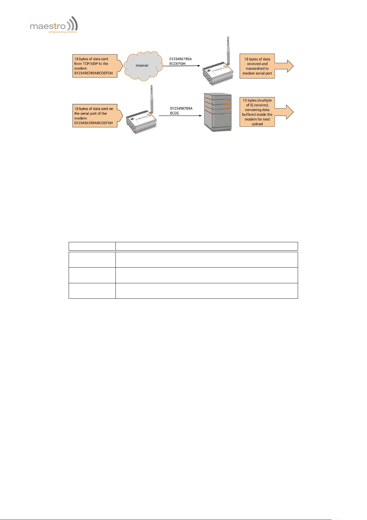
Figure 2.2.1: "AT+IPBUFF=15" example
Syntax: AT+IPBUFF=<buff>
Response: +IPBUFF: <buff>
Defined Values:
<buff> the number of bytes of data to be buffered. Default value is 0 (i.e. no buffering). Valid range is 0 to 100.
Example:
Command Response
AT+IPBUFF=? +IPBUFF: (0-100)
OK
AT+IPBUFF? +IPBUFF: 0
OK
AT+IPBUFF=5 OK
Note: Set IPBUFF value to 5.
Note:
– If the TCP or UDP socket connection is broken, buffered data will be lost.
– Applies only when using automatic or AT command driven TCP/UDP connection.
2.3 Extra TCP/UDP Parameters Setup
Set additional parameters for the TCP/UDP connection, including "keep alive" packet, maximum packet size, TTL
and periodic ping action to monitor the Internet connection status.
AT+IPOPT
Syntax: AT+IPOPT=<CMDType>,<parameter>[,<action>,<con_str>]
Response: +IPOPT: <CMDType>,<parameter>[,<action>,<con_str>]
Defined Values:
<CMDType> 1 DEPRECATED as of R7.52 firmware. "keep alive" packet feature; an empty "keep alive"
packet will be sent out from the modem to avoid socket being closed because of cellular idle
22 Confidential, the whole document is the sole property of Maestro Wireless Solutions ltd.
support@maestro-wireless.com

timeout. <parameter> is used to define the frequency in seconds of the "keep alive" packet.
The value can be set from 1 to 65535, 0 to disable the feature. Default is 0, feature disabled.
2 <parameter> is the maximum size of the outgoing packet in byte. The size can be set from
1 to 1500, 0 to disable the feature. Default value is 1500.
3 <parameter> is the Time To Live (TTL) value of the socket connection in seconds. The value
can be set from 1 to 255, or 0 to disable the feature. Default value is 128.
4 <parameter> is the period in second of calling +IPPING feature, after cellular connected.
The value can be set from 1 to 65535, or 0 to disable the feature. Default is 0, feature
disabled. If +IPPING gives ERROR, modem will trigger the choice set by the <action>
parameter.
5 <parameter> is the data to be sent on first connection. Data is in hexadecimal format,
maximum length is 120 characters. Default is 0.
<action> To specify the action will be taken if a set of ping action fail:
0 do nothing (default).
1 disconnect IP (+IPCONNECT=1,0).
2 reset Maestro modem.
<con_str> To specify a set of data to be sent over the TCP/UDP channel to the remote peer when first connection
is established. Data is entered in Hexadecimal format (01 to FF). Maximum 60 bytes of data can be set.
Example:
Command Response
AT+IPOPT? +IPOPT: 1,0
+IPOPT: 2,1500
+IPOPT: 3,128
+IPOPT: 4,0,0
+IPOPT: 5,""
OK
AT+IPOPT=1,1 OK
Note: enable the keep alive packet feature at 1s rate.
AT+IPOPT=1,300 OK
Note: enable the keep alive packet feature at 5min rate.
AT+IPOPT=2,512 OK
Note: set the size of maximum packet that to be sent to 512
bytes.
AT+IPOPT=3,128 OK
Note: set TTL to 128.
AT+IPOPT=4,60,1 OK
Note: enable ping action every 60 seconds, if ping fail then
disconnect IP.
AT+IPOPT=5,"48454C4C4F" OK
Note: to send "HELLO" to remote peer when connection is
established
AT+IPOPT=? +IPOPT: (1-4),(0-65535)[,(0-2)]
OK
Note:
– +IPOPT options are active only for AUTOTCP/UDP connections. Those don’t apply to +OTCP or +OUDP mode.
– Option 5 of +IPOPT, if used along with option 4 of +AUOPT, will be sent after the +AUOPT prefix.
Confidential, the whole document is the sole property of Maestro Wireless Solutions ltd.
support@maestro-wireless.com
23

24 Confidential, the whole document is the sole property of Maestro Wireless Solutions ltd.
support@maestro-wireless.com
Chapter 3
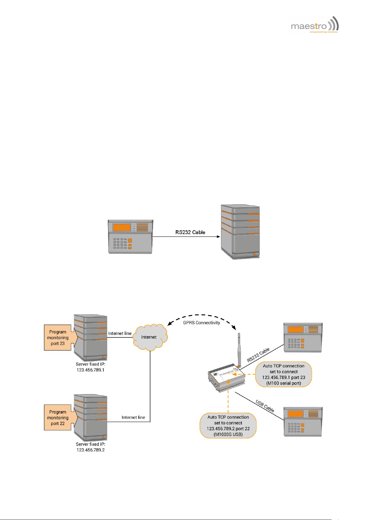
Automatic and self-recovery TCP/UDP connection
The Auto TCP/UDP connection feature is defined for accessing serial devices over the Internet. Modem can be
configured to connect, after power up, to a remote TCP/UDP socket (Client mode) or to wait for the TCP/UDP socket
connection request from remote peer (Server mode).
If the socket connection is unsuccessful or disconnected it will repeat the connection request and back to waiting
stage. This make remote peer can access serial device connected to Maestro modem.
The socket can be set to be disconnected after a period of unconditional connection or zero data traffic.
Figure 3.0.1: Direct Serial Connection
Figure 3.0.2: Example of Automatic Connection(s) over cellular
Confidential, the whole document is the sole property of Maestro Wireless Solutions ltd.
support@maestro-wireless.com
25
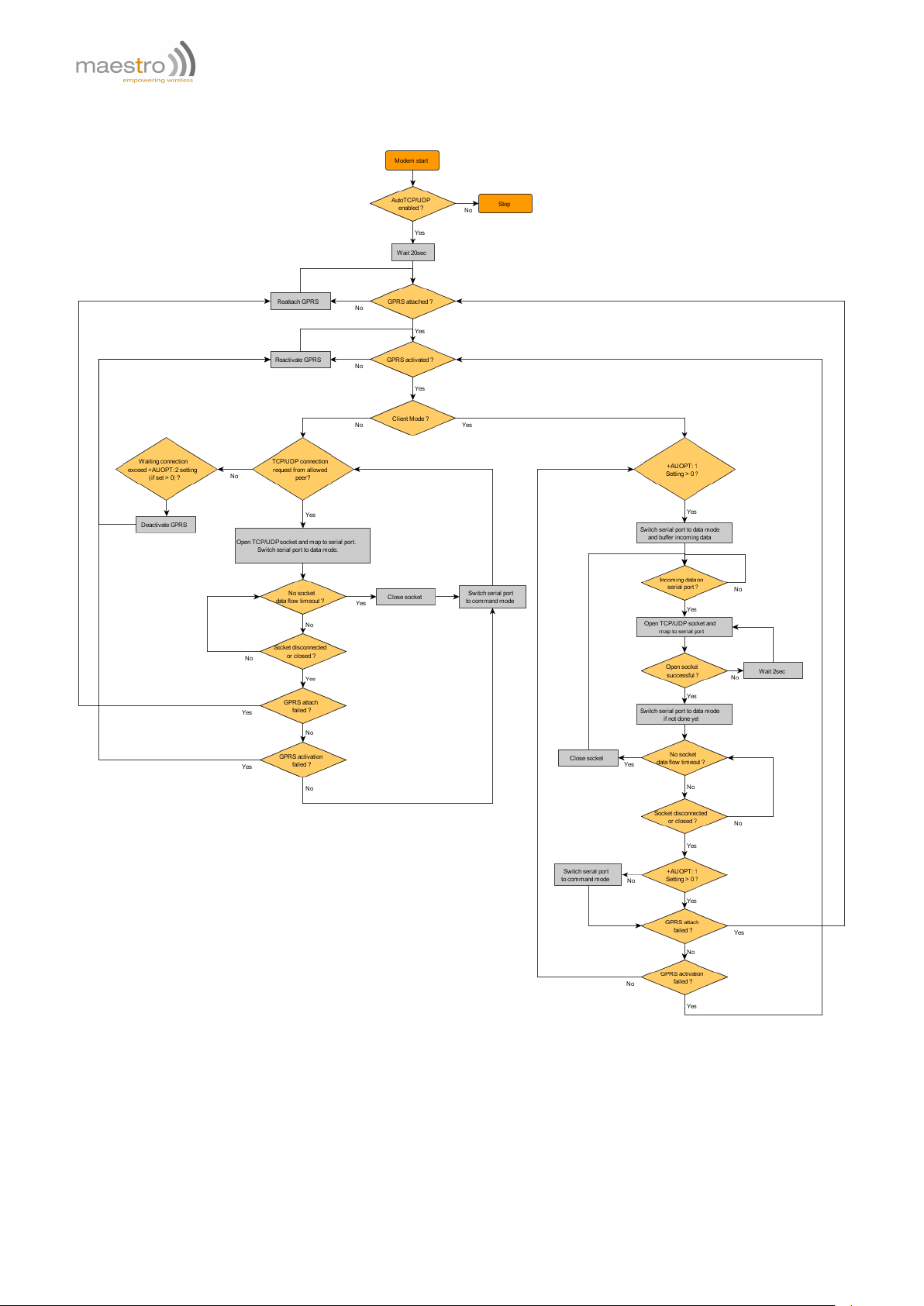
3.1 Flow diagram of Auto TCP/UDP connection function
26 Confidential, the whole document is the sole property of Maestro Wireless Solutions ltd.
support@maestro-wireless.com

3.2 AT commands for Auto TCP/UDP connection
3.2.1 Automatic TCP connection
AT+AUTOTCP
This command controls the modem to start TCP socket connection automatically.
Two socket connections can be established at the same time, mapping to the main Serial port or USB COM port in
case of the M1003G.
Before using AT+AUTOTCP TCP and cellular settings MUST be setup properly using AT+IPTCP and AT+IPGPRS
command respectively. See section 2.2.1 and 2.1.1 for more details.
Syntax: AT+AUTOTCP=<mode>
Response: +AUTOTCP: <mode>
Defined Values:
<mode> 0 disable auto TCP (for main Serial port and USB COM port).
1 enable auto TCP mapped to main Serial port, disable auto TCP mapped to USB COM port.
2 enable auto TCP mapped to USB COM port, disable auto TCP mapped to main Serial port.
3 enable auto TCP on both main and USB COM port.
Example:
Command Response
AT+AUTOTCP=0 OK
Note: disable AutoTCP.
AT+AUTOTCP=1 OK
Note: enable AutoTCP.
AT+AUTOTCP? +AUTOTCP: 1
OK
AT+AUTOTCP=? +AUTOTCP: (0-3)
OK
Note:
– AUTOTCP connection is exclusive to other TCP/UDP feature. See chapter 24.
– Before enabling AUTOTCP, the cellular settings MUST be properly configured by AT+IPGPRS command and
TCP settings by AT+IPTCP command, see section 2.2.1 and 2.1.1 for more details.
– If AUTOTCP is enabled, cellular reconnection will happen automatically if the modem loses cellular IP address.
– USB COM port is not available on the 2G model.
– ONLY cellular PDP context # 1 will be used. Please make sure to setup +IPGPRS settings with <Cid>=1.
– Once AUTOTCP is enabled, it will start the TCP socket connection automatically after 20 seconds.
– Once the TCP connection is established successfully, the serial port will go to data mode, all data entered to
the serial port will be sent to remote TCP peer. No more AT commands will be accepted.
– In TCP connected data mode, the DSR and DCD signals of the serial port will go to high.
– If TCP connection is broken the modem will try to reconnect automatically. During re-connection period serial
port will go back to command mode, and DSR/DCD signal back to low.
Confidential, the whole document is the sole property of Maestro Wireless Solutions ltd.
support@maestro-wireless.com
27

– The setting will be saved, and after power off, the AUTOTCP will be restarted with the 20 seconds delay after
power up.
– To stop auto TCP connection, you need to enter the command AT+AUTOTCP=0 either
1. within 20 seconds after power up,
2. during reconnection (serial port back to command mode),
3. or by SMS (see chapter 10)
– During AUTOTCP operation reset will happen in following cases:
1. If no GPRS connection successful for 2 minutes.
2. If failure to switch UART to Data mode.
3. If undefined condition occurs in connection errors/callback handlers.
3.2.2 Automatic UDP connection
AT+AUTOUDP
This command controls the modem to start UDP connection automatically.
Two socket connections can be established at the same time, mapping to the main Serial port or USB COM port in
case of the M1003G.
Before using AT+AUTOUDP, UDP and cellular settings MUST be setup properly using AT+IPUDP and AT+IPGPRS
command respectively. See section 2.2.2 and 2.1.1 for more details.
Syntax: AT+AUTOUDP=<mode>
Response: +AUTOUDP: <mode>
Defined Values:
<mode> 0 disable auto UDP (for main Serial port and USB COM port).
1 enable auto UDP mapped to main Serial port, disable auto UDP mapped to USB COM port.
2 enable auto UDP mapped to USB COM port, disable auto UDP mapped to main Serial port.
3 enable auto UDP on both main and USB COM port.
Example:
Command Response
AT+AUTOUDP=0 OK
Note : disable AutoUDP.
AT+AUTOUDP=1 OK
Note: enable AutoUDP.
AT+AUTOUDP? +AUTOUDP: 1
OK
AT+AUTOUDP=? +AUTOUDP: (0-1)
OK
Note:
– AUTOUDP connection is exclusive to other TCP/UDP feature. See chapter 24.
– Before enabling AUTOUDP, cellular settings MUST be properly set by AT+IPGPRS command and UDP settings
by AT+IPUDP command, see section 2.2.2 and 2.1.1 for more details.
28 Confidential, the whole document is the sole property of Maestro Wireless Solutions ltd.
support@maestro-wireless.com

– If AUTOUDP is enabled, cellular reconnection will happen automatically if the modem loses cellular IP address.
– USB COM port is not available on the 2G model.
– ONLY cellular PDP context # 1 will be used. Please setup +IPGPRS settings with <Cid>=1.
– Once AUTOUDP is enabled, it will start the UDP socket connection automatically after 20 seconds.
– Once the UDP connection is established successfully, the serial port will go to data mode, all data entered to
the serial port will be sent to remote UDP peer. No more AT commands will be accepted then.
– In UDP connected data mode, the DSR and DCD signals of the serial port will go to high.
– If UDP connection is broken the modem will try to reconnect automatically. During re-connection period serial
port will go back to command mode, and DSR/DCD signal back to low.
– The setting will be saved, and after power off, the AUTOUDP will be restarted with the 20 seconds delay after
power up.
– To stop AUTOUDP connection, you need to enter the command AT+AUTOUDP=0 either
1. within 20 seconds after power up,
2. during reconnection (serial port back to command mode),
3. or by SMS (see chapter 10).
– Due to the nature of UDP socket connection, AT+AUTOUDP=0 may not be able to disconnect. in this case you
may send command AT+IPCONNECT=1,0 to disconnect cellular connection.
– During AUTOUDP operation reset will happen in following cases:
1. If no GPRS connection successful for 2 minutes.
2. If failure to switch UART to Data mode.
3. If undefined condition occurs in connection errors/callback handlers.
3.2.3 Buffering time
AT+AUFCM
This command controls the buffering time of TCP/UDP data sent to remote peer when using automatic or AT command driven TCP/UDP connection.. Data coming from serial will be buffered for a "delay" period before being sent
out.
Syntax: AT+AUFCM=<delay>
Response: +AUFCM: <delay>
Defined Values:
<delay> Delay units between sending buffered data to TCP/UDP peer. The actual delay time is calculated by the
value of <delay> times 18.5 ms. So if <delay> is equal to 2 that means data will be sent to remote peer
every 37ms (or immediately if internal buffer is full). Increasing this value can make the data packet size
bigger especially when data flow is slow, thus reducing overhead. Default value: 2. Possible value: 1 to
255.
Example:
Command Response
AT+AUFCM=2 OK
Note: set the +AUFCM value to 2.
AT+AUFCM? +AUFCM: 2
OK
AT+AUFCM=? +AUFCM: (1-255)
OK
Confidential, the whole document is the sole property of Maestro Wireless Solutions ltd.
support@maestro-wireless.com
29

Note:
– If the value is set too high the maximum data transfer speed may be decreased.
– Applies only when using automatic or AT command driven TCP/UDP connection.
3.2.4 Optional parameters
AT+AUOPT
This command lets user to set option parameters to control socket connection. There are three option parameters:
1. Socket idle period: period of connected socket with zero data traffic, socket will be closed when timeout.
2. Server idle period: period of connected socket with zero data traffic, cellular will be deactivated and reactivated
when timeout.
3. Socket connect period: period of maximum allowed connection time, socket will be closed when timeout.
4. UDP prefix: will send a data set to server on each data connection.
5. Heartbeat period: send a heartbeat packet on period.
6. Serial prefix: will output a data on serial on each data connection.
Option Applicable mode Serial port behavior if option enabled
1 Client / Server As client: in data mode all the time, data are buffered.
As server: in data mode when socket is connected, in command
mode when socket is not connected (data not buffered).
2 Server n/a
3 Client / Server Depends on <option> #1 setting.
4 Client / Server n/a
5 Client n/a
6 Client / Server n/a
Syntax: AT+AUOPT=<option>,<val>
Response: +AUOPT: <option>,<val>
Defined Values:
<option>
1 socket idle period (for client and server mode). After Auto TCP/UDP socket is connected, if there is no
data transport, in both direction, for more than <val> (in minutes) the socket will be disconnected. Please
read notes below when using it with TCP client mode.
<val> Unit is in minute. Default value is 0 (connection control disabled). Valid range is 0 to 65535.
2 server idle period (for server mode only). If the unit set as a server stays in listening mode for more
than the <val> (in minutes) the PDP context will be deactivated, then reactivated, and server listening
modem will be resumed. This option prevent the network from closing because of no data flow after
some period.
<val> Unit is in minute. Default value is 0 (connection control disabled). Valid range is 0 to 65535.
3 socket connect period (for client and server mode). If a Auto TCP/UDP socket stays connected for more
than the <val> (in minutes) the socket will be disconnected.
30 Confidential, the whole document is the sole property of Maestro Wireless Solutions ltd.
support@maestro-wireless.com
 Loading...