

Page 1

103E-OG0907-00
QUICK OPERATION GUIDE
MINI-CRAWLER CRANE
Serial No. D0001 and up
• This operation guide explains basic operation of the machine. Before starting work, always
conduct checks written in “2.1 Checking Before Operation” in the separate “Operation
Manual”.
For safety cautions and detailed operation of the machine not explained in this book, please
read and understand the separate “Operation Manual” before operating this machine.
• This operation guide does not replace the operation manual. This is just a short helpdesk
information paper to assist the trained operator of the crane with the basic operation of the
crane. For complete and detailed information we refer to the operation manual of the crane.
Page 2

CONTENTS
ITEM Page
1. TRAVELLING AND CRANE OPERATION UNITS 3
2. INSTRUMENT PANEL SECTIONS 3
3. ST ARTING AND STOPPING THE E N GINE 4
4. TRA VELLING OPERATION 4
5. OUTRIGGER OPERATION 5
6. CRANE OPERATION 7
7. MOMENT LIMITER (OVERLOAD DETECTOR) 8
8. REMOTE CONTROL 9
8.1 PROCEDURE IN THE OPERATION MODE 9
8.2 OPERATION IN OUTRIGGER MODE 10
8.3 OPERATION IN CRANE MODE 11
8.4 AUTOMATIC HOOK STOW F UNCTION 1 1
8.5 SET-UP AN D CANCEL MICRO SPEED 1 1
9. ELECTRIC MOTOR 11
FOR SAFE USE OF MACHINE
This manual classifies the risks into the following three categories to present the details of the safety
labels in easy-to-understand manner.
This denotes that there is an imminent hazard which will cause serious pe rsonal
injury or death.
The method of hazard circumvention is state d.
This denotes that there is a hazard whic h can cause serious personal injury o r
death.
The method of hazard circumvention is state d.
This denotes that there is a potential hazard which may cause minor or
moderate personal injury or serious damage to this machine.
The method of hazard circumvention is state d.
This manual also provides the following to indicate what must be observed for the sake of the machine and
what will be of help.
This denotes that failure to handle the machine properly may damage the machine
or shorten its life.
This denotes helpful information.
CAUTION
NOTES
Page 3
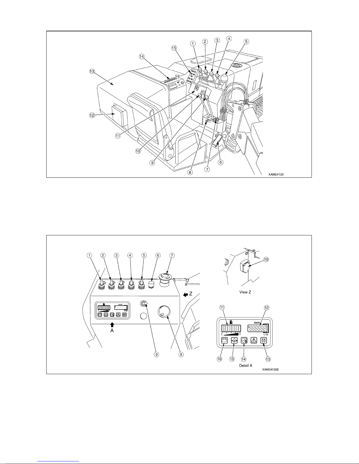
1. TRA VELLING AND CRANE OPERATION UNITS
(1) Slewing lever
(2) Boom telescoping lever
(3) Winch lever
(4) Boom derricking lever
(5) Outrigger un-set warning lamp
(6) Acceleration pedal
(7) Level
(8) Travelling lock lever
(9) Right travelling lever
(10) Left travelling lever
(11) Moment limiter display panel
(12) Power supply box
(13) Power unit cover
(14) Instrument panel
(15) Outrigger operation panel
2. INSTRUMENT PANEL SECTIONS
(1) Headlight switch
(2) Crane high-speed switch
(3) Hook stowing switch
(4) Travelli ng high-spe ed swit ch
(5) Boom stowing switch
(6) Horn switch
(7) Emergency stop switch
(8) Starter switch
(9) Engine and electric motor switch
(MC305CRME-2 only)
(10) Emergency stop cancel switch
(1 1) Fuel gauge
(12) Hour meter
(13) Pre-heat monitor
(14) Engine water temperatu re
monitor
(15) Engine oil pressure monit or
(16) Battery charge monitor
-3-
Page 4
3. STARTING AND STOPPING THE ENGINE
[1] STARTING THE ENGINE
1. Insert the key and turn it left (preheating) until the “preheat monitor” goes out.
2. Step on the acceleration pedal to half of it’s full stroke (medium speed).
3. Turn the key to the right to start the crane.
[2] STOPPING THE ENGINE
1. Release your foot from the acceleration pedal to chang e the engine speed to low idling.
2. Turn the starter switch key to the OFF position. The engine stops.
4. TRAVELLING OPERATION
[1] STARTING/MOVING MACHINE
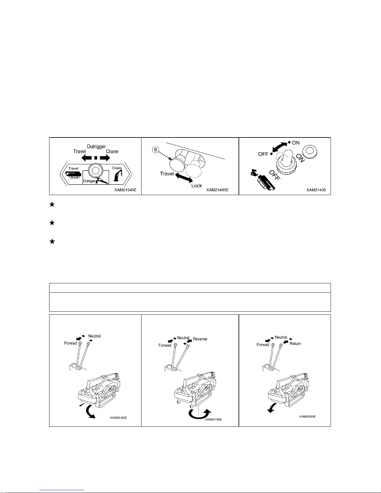
To start travelling, operate the work selector switch to the TRAVEL position and then operate the travelling
lock levers to the TRAVEL position (push to the lef t).
To change travelling speed, operate the travelling high-speed switch to the ON position. The pilot lamp of
the switch lights up and the machine will be in the “high-speed travelling mode”.
To move the machi ne, there a re two lev ers which work i ndependen tly. The left lever operates the left rubber
track, the right lever operates the right ru bber track.
• To move forward, push both levers to the front.
• To move backward, pull both levers to the back.
[2] CHANGING PATH OF MACHINE
NOTES
When changing the path of the machine, always operate the travelling high-speed switch in the OFF
position
Changing path while moving
Forward/Backward
Spin turns
Changing the machine direction while being stopped
[3] STOPPING/PARKING MACHINE
Return the left and right travelling levers to the NEUTRAL position at the same time. The brakes are
automatically applied and the machine will stop.
-4-
Page 5
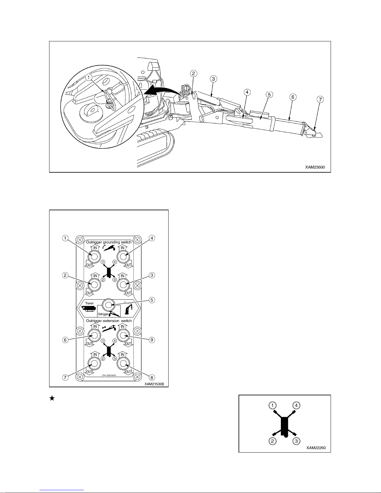
5. OUTRIGGER OPERATION
(1) Position pin (5) Outer box
OUTRIGGER COMPONENTS
(2) Rotary (6) Inner box
(3) Outrigger setting cylinder (7) Outrigger adapter (Foot)
(4) Outrigger extension cylinder
-5-
(1) Outrigger (1) setting switch
(2) Outrigger (2) setting switch
(3) Outrigger (3) setting switch
(4) Outrigger (4) setting switch
(5) Work selector switch (TRAVEL, OUTRIGGER, CRANE)
(6) Outrigger (1) extension switch
(7) Outrigger (2) extension switch
(8) Outrigger (3) extension switch
(9) Outrigger (4) extension switch
OUTRIGGER OPERA TION PANEL
There are four outriggers installed on the machine. Although the setting
method is described for just one outrigger (outrigg er (4), set the other three
outriggers in the same way).
Page 6
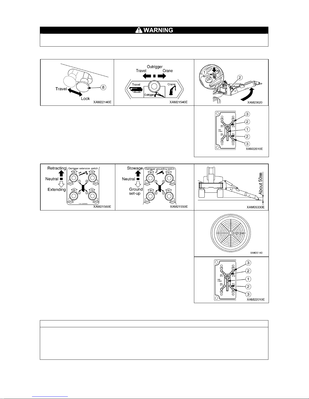
[1] OUTRIGGER SET UP OPERA TION
It is forbidden to work with the crane without the outriggers.
(1) T ASKS T O BE PERFORMED UPON ENGINE ST OP
1. Set the lock lever in “LOCK” position.
2. Operate the work selector switch to the “OUTRIGGER” position.
3. Rotate the outriggers and secure with the position pin.
4. Verify that the four outrigge r extension lamp s (2) (green) on the outrigger
display are ON.
(2) T ASKS T O BE PERFORMED AFTER STARTING ENGINE
1. Push down outrigger extension switches and extend the outriggers as
much as possible.
2. Push down outrigger setting switches and put the outriggers down O NE
by ONE until they all just touch the ground.
3. Then use the outriggers TWO by TWO to st abilize the crane.
4. Check the bubble in the level in order to make sure the crane is in the
correct position.
5. Make sure the rubber tracks are about 50mm above the ground.
6. Verify that the four outrigger setting lamps (3) (green) on the outrigger
display are ON.
[2] OUTRIGGER STOWING OPERA TION
Reverse the outrigger set up procedure to stow the outrigger .
NOTES
There are outrigger safety interlock devices.
The outriggers are not enabled if each rotary position pin is not inserted correctly and the boom is not at the
stowed position. (Stowed position : the boom is fully retracted, fully down and slewed over the center of the
crane until the light (1) is green)
-6-
Page 7
6. CRANE OPERA TION
[1] OPERA TIONS BEFORE CRANE OPERA TIONS
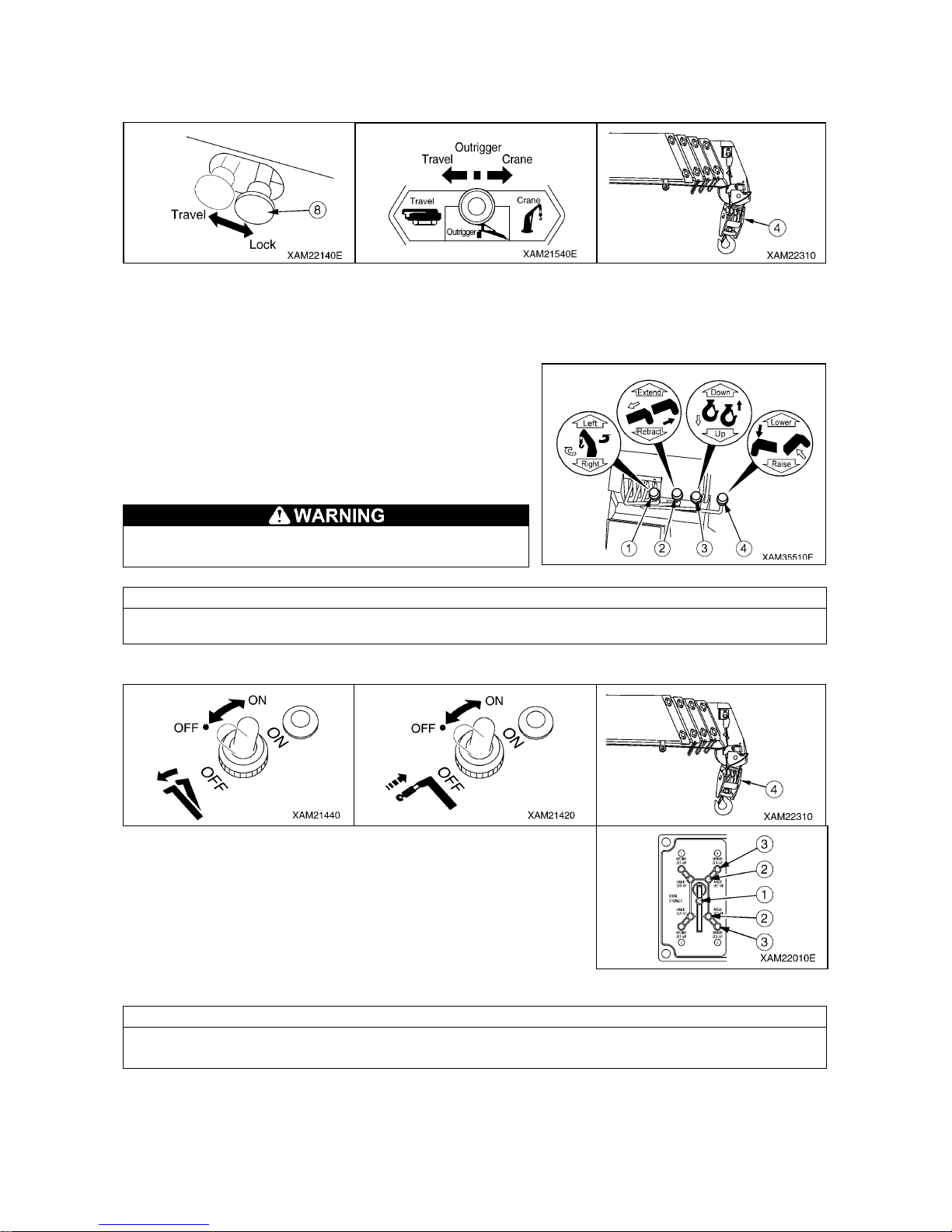
1. Set the lock lever in “LOCK” position.
2. Operate the work selector switch to the “CRANE” position
3. Operate the winch lever to the DOWN side to loosen the hook bloc k from the stowing position.
[2] CRANE OPERA TIONS
There are 4 possible crane operations :
(1): Slewing (forward: counterclockwise, backward: clockwise)
(2): Boom telescoping (forward: extend, backward: retract)
(3): Hook rasing and lowering
(forward: lowering, backward: raising)
(4): Boom derricking (forward: lowering, backward: raising)
Never let the hook block touch the ground or let the
winch rope slacken. This could damage the winch rope.
NOTES
When extending the boom, always lower the hook simultaneously.
[3] CRANE STOWING OPERA TION
1. Completely retract the boom and slew until the boom is over the center of
the crane. Lower the boom to the maximum (it stops automatica lly).
2. With the boom stowing switch moved to the ON po sition, operate the boom
derricking lever again to the LOWER side to stow the boom.
3. With the hook stowing switch at the ON position, operate the winch lever to
the UP side again and slowly raise the hook block to stow the block at the
bottom of the boom end.
4. Verify that the boom stowi ng lamp (1) (green) on the outrigge r display lights
up.
NOTES
There are crane safety interlock devices.
The crane operation is enabled only when all four outriggers are extended and grounded.
-7-
Page 8
7. MOMENT LIMITER (OVERLOAD DETECTOR)
MOMENT LIMITER FUNCTIONS
[1] PROHIBITED ACTIONS AFTER AUTO ST OP
The following crane operations are prohibited after the crane has stopped automatically due to
overloading. These operations may cause overturning of the machine or breakage of the boom and
are very dangerous.
• Boom lowering operation • Boom extending operation • Hook raising operation
• Crane slewing operation
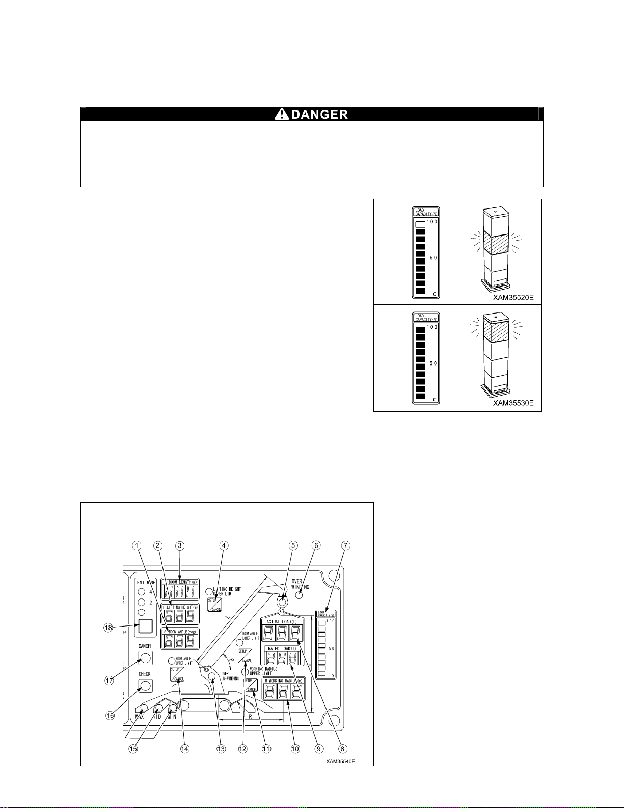
[2] OVERLOAD WARNING
1. PRE-WARNING:
“Actual load” is 90 to less than 100 % of the “rated total loa d”.
• The Load capacity display indicates 90%.
• The alarm bleeps intermittently .
• The working status lamp changes from green to yell ow .
2. LIMIT WARNING:
“Actual load” is 100 % or higher than the “rated total load”.
• The Load capacity display indicates 100% .
• The alarm sounds continuously.
• Voice messa ge of “Overloading” sounds.
• The working status lamp changes from yel low to red.
• The hazardous operation of the crane stop s automatically.
(Hook raising, boom lowering, boom extending)
3. RECOVERY OPERATION AFTER A UTO ST OP
If the system stops automatically, promptly perform one of following the recove ry operation caused by overloading.
(1) Hook lowering operation
(2) Boom retracting operation
(3) Boom raising operation (never raise the boom to li ft the load from the ground, always winch the load clear of the
ground before any other operation is performed)
-8-
MOMENT LIMITER DISPLAY
(1) Boom angle display
(2) Lifting height display
(3) Boom length display
(4) Boom lifting height upper limit switch
(5) Load factor LED
(6) Over hoist detection LED
(7) Load capacity display
(8) Actual load display
(9) Rated total load display
(10) Working radius display
(1 1) Working radiu s upper limit switch
(12) Boom angle lower limit switch
(13) Over un-winding LED
(14) Boom angle upper limit switch
(15) Outrigger extension LED
(16) Check switch
(17) Cancel switch
(18) Fall mode selector & searcher hook
mode switch
Page 9
8. REMOTE CONTROL
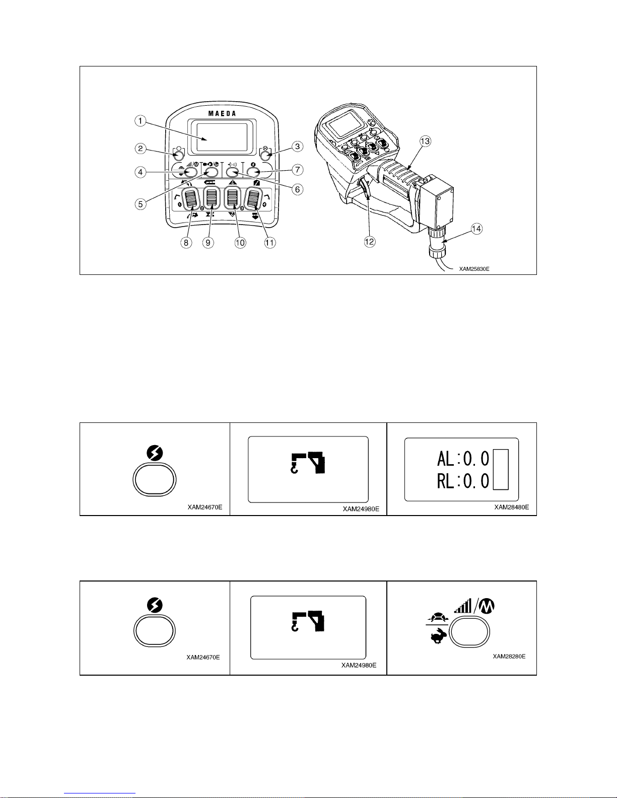
TRANSMITTER
(1) LCD Screen
(2) Start/Reset Button
(3) Stop/EMO Button
(4) Speed/Mode Button
(5) Hook Stow/Setting Button
(6) Horn Button
(7) Power Switch
(8) Slewing/No.1 Outrigger Operation Lever
(9) Boom Telescoping/No.2 Outrigger Operation Lever
(10) Hook Raising and Lowering/No.3 Outrigger Operation Lever
(1 1) Boom derricking/No.4 Outrigger Operation Lever
(12) Accelerator Lever
(13) Grip
(14) Connection Cable
8.1 PROCEDURE IN THE OPERATION MODE
[1] CALL UP CRANE MODE
1. Push the Power button to turn ON the Transmitter .
2. The “Crane mark” is displayed in the LCD scree n for about 2 seconds.
3. The crane is ready for operation.
[2] CALL UP OUTRIGGER MODE
1. Push the Power button to turn ON the Transmitter .
2. The “Crane mark” is displayed in the LCD scree n for about 2 seconds.
3. While the “Crane mark” is displayed, push the speed button for about 2 seconds. The LCD provides the screen for
selecting “CRANE MODE” or “OUT RIGGER MODE”.
-9-
Page 10
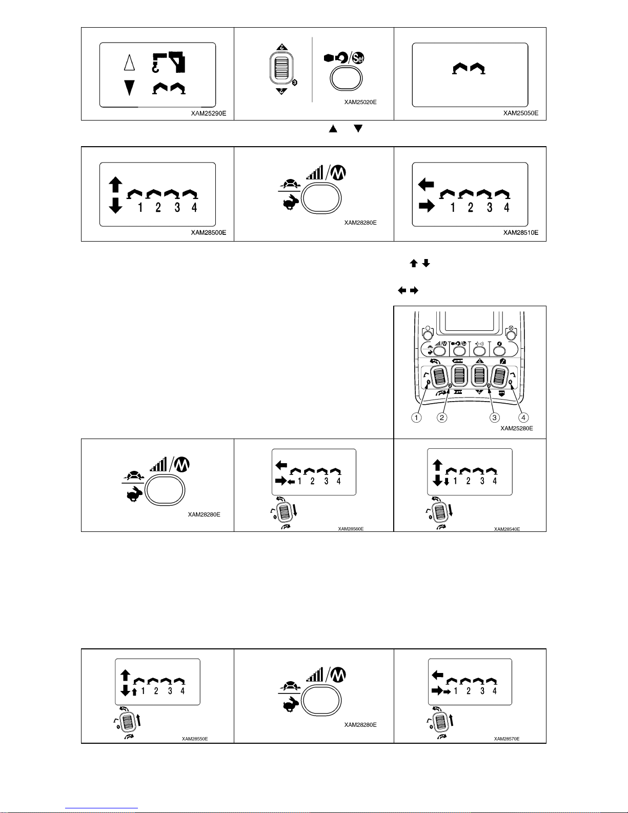
4. Use the Hook raising and lowering Lever to shift the cursor (
or ), and push the Setting button when the cursor
points to the “OUTRIGGER”.
5. The operation mode is already switched to the “O UTRI GGER MODE”, thus the “Outrigger mark” is exhibited. So on
after, it enters into “Ground setting mo de”, then the mark turn s to “Ground setting (
)“.
6. To shift to “E xtension mode”, push the Speed/Mode b utton, whil e the LCD screen shows the “Grou nd setting mode”.
Then the mode is switched to “Extension mode”; the mark turns to “Extension (
)”.
8.2 OPERA TION IN OUTRIGGER MODE
The outriggers of the crane are numbered from 1 to 4 and these correspond
to the numbers of each operation lever on the rem ote control.
If you want to ST ART any action, always use the operatio n lever first and only
afterwards pull the accelerator (slowly).
If you want to END any action, first release the accelerator slowly, and then
release the operation lever .
1. Push Speed/ Mode button, the operation mod e is switched to “Outrigger Extensi on mode”.
2. Turn one of t he outrigger operation l evers to “Extend (lower)”
(Extend the outriggers (by pushing down the levers) a s much as possible)
3. Push Speed/ Mode button, the operation mod e is switched to “Ground setti ng mode”.
4. Put the outriggers down ONE by ONE (by pushing do wn the levers) until they all just touch the ground.
5. Then use the outriggers TWO by T WO to stabili ze the crane.
6. Check the bubble in the level in order to make sure th e crane is in the correct positi on.
7. Make sure the rubber tracks are about 50mm ab ove the ground.
For stowing the outriggers: push the operation l evers up.
-10-
Page 11
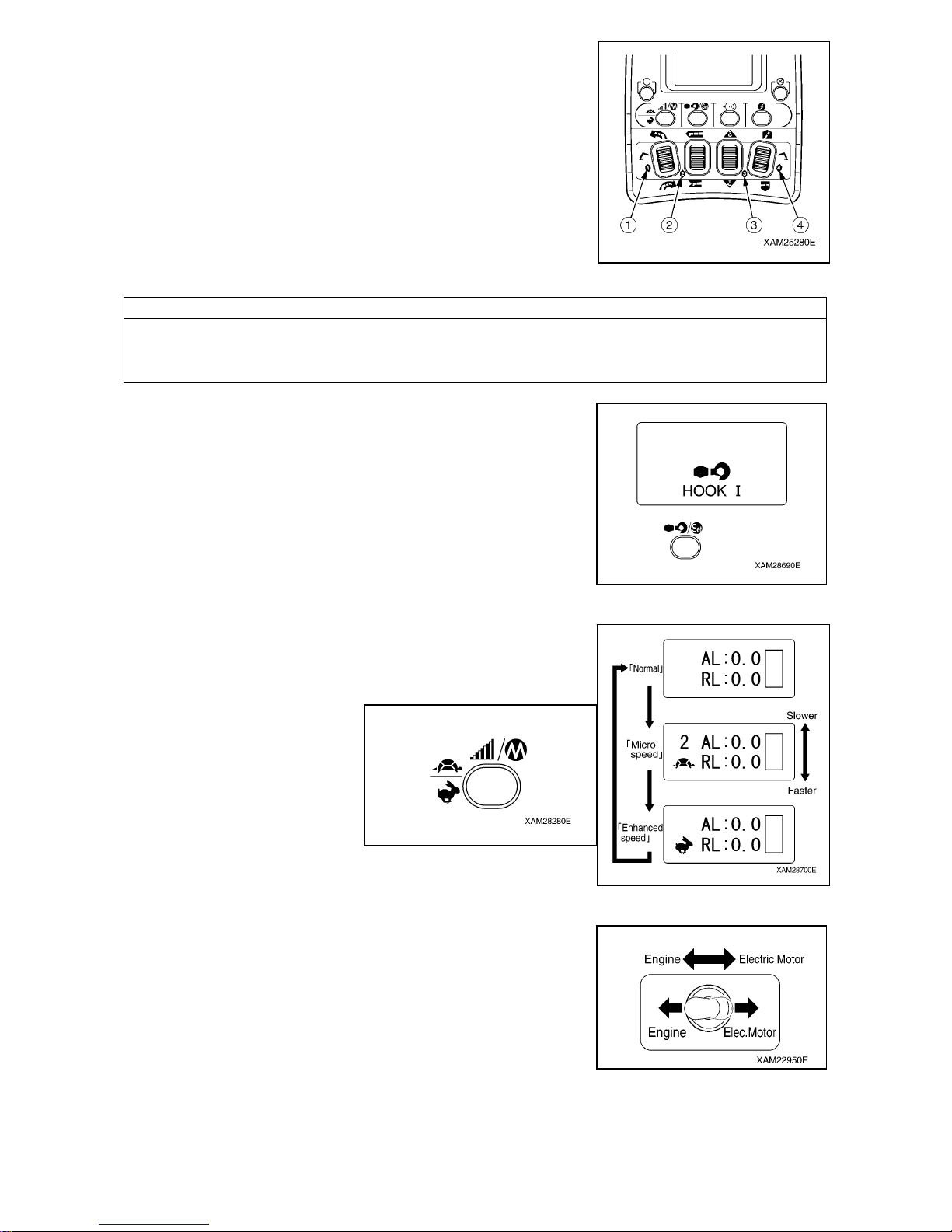
8.3 OPERA TION IN CRANE MODE
Four Crane operation switches are provided. Each controls the following
operation, respectively. (See the figure on the right.)
(1): Slewing (upper: counterclockwise, lower: cloackwise)
(2): Boom telescoping (upper: extend, lower: retract)
(3): Hook rasing and lowering (upper: raising, lower: lowering)
(4): Boom derricking (upper: raising, lower: low ering)
8.4 AUTOMATIC HOOK STOW FUNCTION
NOTES
This automatic hook stow function is not available in the “Micro Speed mode” or “Enhanced Speed mode”. To
stow the hook, always cancel either the “Micro Speed mode” or “Enhanced Speed mode”. For the speed
modes, please see 8.5. Set up and Cancel Micro Speed
1. Configure the boom to the travelling condition and push the Hook raising
and lowering/No.2 outrigger operation lever to “Raise (upper)”, then pull the
Accelerator lever. Keep raising the hook until it touches to the over-hoist
detector weight and automatically stops.
2. When the hook automatically stops, push the Hook stow/Setting button.
LCD screen in the Transmitter displays “HOOK I”.
3. Keep pushing the Hook stow/Setting button, pull the Accelerator lever
slowly. The hook will be raised to the proper stow position. (Stop this
operation once the hook block touches the boom.)
8.5 SET-UP AND CANCEL MICRO SPEED
The speed of the crane can also be controlled by the MICRO SPEE D MODE.
Just push the speed/mode button and each push will forward the LCD screen
indication as shown in the diagram to the right.
9. ELECTRIC MOTOR
If electric motor is required, please att a ch a electri c cable and t urn the engin e
and electric motor switch to the “Electric Motor” (right) position. To start the
electric motor, simply insert the key into the main starter switch and turn on
the engine. (Pre-heating is not necessary.)
All other operations (travelling – outriggers – crane) are the same as
described in previous chapters.
-11-
Page 12

MAEDA MINI-CRAWLER CRANE MC-305-2C QUICK OPERATION GUIDE
Document No: 103E-OG0907-00
First edition: July 31, 2009
Issued by Maeda Seisakusyo Co., Ltd.
1095 Onbegawa, Shinonoi
Nagano, Nagano 388-8522,
Japan
No part of this manual can be reproduced in any from without permission
-12-
 Loading...