

Page 1

103E-OM1805-08
OPERATION MANUAL
MINI-CRAWLER CRANE
Serial No. D0338 and up
Unsafe use of this machine may cause serious injury or death. Operators
must read this manual before operating this machine. This manual should
be kept near the machine for reference and periodically reviewed by all
personnel who will come into contact with it.
NOTICE
MAEDA has Operat ion Manual written in some oth er languages. If a fore ign
language manual is necessary , contact your local distributor for availability.
Page 2

Page 3

0-1
CONTENTS
ITEM
Page
INTRODUCTION
1- 1
1. INTRODUCTION 1- 2
2.FOR SAFE USE OF MACHINE 1- 3
3. MACHINE OVERVIEW 1- 4
3.1 SPECIFIED OPERATIONS 1- 4
3.2 MACHINE CONFIGURATION 1- 4
3.3 MACHINE FUNCTIONS 1- 5
4. QUALIFICATION FOR OPERATION 1- 6
4.1 QUALIFICATION FOR CRANE OPERATION 1- 6
5. TERMINOLOGY 1- 7
5.1 DEFINITIONS OF TERMS 1- 7
5.2 DIAGRAM OF WORKING RADIUS AND LIFTING HEIGHT 1- 8
5.3 RATED TOTAL LOAD TABLE 1- 9
5.4 LOAD INDICATOR 1-15
SAFETY
2- 1
1. BASIC PRECAUTIONS 2- 2
2. DRIVING RELATED PRECAUTIONS 2- 7
2.1 BEFORE STARTING ENGINE 2- 7
2.2 AFTER STARTING ENGINE 2- 8
2.3 WORKING WITH CRANE 2-12
3. TRANSPORT PRECAUTIONS 2-21
4. BATTERY HANDLING PRECAUTIONS 2-23
5. MAINTENANCE PRECAUTIONS 2-25
5.1 PRECAUTIONS BEFORE MAINTENANCE 2-25
5.2 PRECAUTIONS DURING MAINTENANCE 2-27
6. SAFETY LABEL LOCATIONS 2-32
7. WEEE DIRECTIVE LABEL LOCATIONS 2-42
OPERATION
3- 1
1. MACHINE EACH SECTION 3- 2
1.1 MACHINE EACH UNIT 3- 2
1.2 TRAVELING AND CRANE OPERATION UNITS 3- 3
1.3 INSTRUMENT PANEL SECTIO NS 3- 6
1.3.1 DESCRIPTION OF EACH SWITCHES 3- 7
1.3.2 DESCRIPTION OF EACH MONITORS 3-10
1.3.3 DESCRIPTION OF FUSES 3-12
1.4 OUTRIGGER OPERATION PANEL 3-13
1.5 OUTRIGGER SAFETY DEVICES 3-15
1.5.1 FUNCTIONS OF OUTRIGGER SAFETY DEVICES 3-15
1.5.2 NAMES AND DESCRIPTIONS OF OUTRIGGER DISPLAY 3-16
1.5.3 OUTRIGGER UN-SET WARNING LAMP 3-17
1.6 MOMENT LIMITER (OVERLOAD DETECTOR) 3-18
1.6.1 MOMENT LIMITER CONFIGURATION 3-18
1.6.2 FUNCTION OF MOMENT LIMITER 3-19
Page 4

0-2
ITEM
Page
1.6.3 MOMENT LIMITER OPERATIONS 3-20
1.6.4 NAMES OF MOMENT LIMITER DISPLAY UNIT 3-22
1.6.5 MOMENT LIMITER FUNCTIONS 3-29
1.6.6 MOMENT LIMITER STARTING STATUS 3-31
1.6.7 MOMENT LIMITER WORKING ENVELOPE SETTING 3-32
1.6.8 EMERGENCY STOP CANCEL SWITCH 3-33
1.6.9 MOMENT LIMITER ERROR CAUSES AND ACTIONS TO BE TAKEN 3-34
1.7 OVER HOIST DETECTOR 3-35
1.8 OPERATION SEAT 3-36
1.9 ENGINE HOOD 3-37
1.10 MACHINERY COVER 3-38
2. OPERATIONS 3-40
2.1 CHECKING BEFORE OPERATION 3-40
2.1.1 CHECKING BEFORE STARTING ENGINE (VISIBLE CHECKS) 3-40
2.1.2 CHECKING BEFORE STARTING ENGINE 3-43
2.1.3 CHECKING AFTER STARTING ENGINE 3-56
2.2 STARTING ENGINE 3-66
2.2.1 NORMAL ENGINE START 3-66
2.2.2 STARTING ENGINE IN COLD WEATHER 3-67
2.3 OPERATIONS AND CHECKS AFTER STARTING ENGINE 3-68
2.4 BREAKING-IN MACHINE 3-70
2.5 MACHINE TRAVELING POSTURE 3-70
2.6 STARTING MOVING MACHINE 3-71
2.7 CHANGING MACHINE TRAVELING MODE 3-72
2.8 CHANGING PATH OF MACHINE 3-72
2.9 STOPPING/PARKING MACHINE 3-74
2.10 STOPPING ENGINE 3-75
2.11 INSPECTION AFTER STOPPING ENGINE 3-75
2.12 CAUTIONS IN DRIVING 3-76
2.13 DESCRIPTION ON OUTRIGGER AND CRANE SAFETY DEVICES 3-78
2.14 OUTRIGGER SETTING OPERATION 3-82
2.14.1 NAME OF OUTRIGGER COMPONENTS 3-84
2.14.2 OUTRIGGER SETTING OPERATION 3-84
2.15 CAUTIONS BEFORE CRANE OPERATION 3-88
2.16 OPERATIONS BEFORE CRANE OPERATIONS 3-89
2.17 CRANE OPERATION POSTURE 3-90
2.18 HOOK RAISING/LOWERING OPERATION 3-90
2.19 BOOM DERRICKING OPERATION 3-91
2.20 BOOM TELESCOPING OPERATION 3-92
2.21 SLEWING OPERATION 3-93
2.22 ACCELERATION OPERATION 3-93
2.23 CRANE STOWING OPERATION 3-94
2.24 OUTRIGGER STOWING OPERATION 3-96
2.25 DOS AND DON’TS DURING CRANE OPERATIONS 3-100
Page 5

0-3
ITEM
Page
3. HANDLING RUBBER TRACKS 3-102
3.1 GOOD USE 3-102
3.2 WARRANTY 3-102
3.3 DOS AND DON’TS 3-103
3.4 CAUTIONS IN USING RUBBER TRACKS 3-104
4. HANDLING WIRE ROPES 3-106
4.1 BENCH MARK FOR REPLACING WIRE ROPES 3-106
4.2 What TO DO WITH TWISTED WINCH WIRE ROPE 3-107
5. TRANSPORTATION 3-108
5.1 LOADING/UNLOADING 3-108
5.2 HOISTING MACHINE 3-109
5.3 CAUTIONS IN LOADING MACHINE 3-110
5.4 CAUTIONS DURING TRANSPORTATION 3-110
6. HANDLING IN COLD WEATHER 3-111
6.1 PREPARING FOR LOW TEMPERATURE 3-111
7. LONG-TERM STORAGE 3-113
7.1 BEFORE STORING MACHINE 3-113
7.2 DURING STORAGE 3-113
7.3 AFTER STORAGE 3-113
8. HANDLING BATTERY 3-114
8.1 CAUTIONS IN HANDLING BATTERY 3-114
8.2 REMOVING/INSTALLING BATTERY 3-115
8.3 CAUTIONS IN CHARGING BATTERY 3-116
8.4 STARTING ENGINE WITH BOOSTER CABLE 3-117
9. TROUBLESHOOTING 3-119
9.1 ELECTRICAL COMPONENTS 3-119
9.2 MACHINE BODY 3-120
9.3 ENGINE 3-121
INSPECTION AND MAINTENANCE
4- 1
1. PRECAUTIONS FOR MAINTENANCE 4- 2
2. BASIC MAINTENANCE 4- 4
3. LEGAL INSPECTION 4- 6
4. CONSUMABLES 4- 6
5. LUBRICATING OIL 4- 7
5.1 USE OF LUBRICATING OIL ACCORDING TO TEMPERATURES 4- 7
6. ACCESSORY TOOLS AND STANDARD TIGHTENING TORQUE 4- 8
6.1 ACCESSORY TOOLS 4- 8
6.2 STANDARD TIGHTENING TORQUE LIST 4- 8
7. INSPECTION AND MAINTENANCE LIST 4-10
8. MAINTENANCE PROCEDURES 4-12
8.1 INITIAL 10 HOUR MAINTENANCE 4-12
8.2 INITIAL 50 HOUR MAINTENANCE 4-12
8.3 INITIAL 250 HOUR MAINTENANCE 4-12
8.4 CHECKING BEFORE OPERATION 4-12
8.5 IRREGULAR MAINTENANCE 4-13
8.6 MAINTENANCE EVERY 30 HOURS 4-22
Page 6

0-4
ITEM
Page
8.7 MAINTENANCE EVERY 50 HOURS 4-24
8.8 MAINTENANCE EVERY 250 HOURS 4-28
8.9 MAINTENANCE EVERY 500 HOURS 4-32
8.10 MAINTENANCE EVERY 1000 HOURS 4-36
8.11 MAINTENANCE EVERY 1500 HOURS 4-45
8.12 MAINTENANCE EVERY 2000 HOURS 4-45
SPECIFICATIONS
5- 1
1. SPECIFICATION LIST 5- 2
2. SPECIFICATION DIMENSIONAL DRAWING 5- 4
3. DIMENSIONAL DRAWING OF OUTRIGGER WIDTH 5- 5
4. RATED TOTAL LOAD TABL E 5- 6
5. WORKING RADIUS AND LIFTING HEIGHT 5- 9
INTERACTIVE REMOTE CONTROL
6- 1
1. OUTLINE OF REMOTE CONTROLLER 6- 2
1.1 FEATURE 6- 2
1.2 CONFIGURATION 6- 2
1.3 FUNCTIONS OF REMOTE CONTROL SYSTEM 6- 3
2. SAFETY PRECAUTIONS 6- 4
2.1 For Safety Operations 6- 4
2.2 PRECAUTIONS FOR CRANE OPERATION 6- 6
2.2.1 PRIOR TO STARTING ENGINE 6- 6
2.2.2 SUBSEQUENT TO STARTING ENGINE 6- 7
2.2.3 TERMINATING THE OPERATION 6- 7
3. LOCATIONS OF SAFETY LABELS 6- 8
4. COMPONENTS OF THE TRANSMITTER 6-10
5. COMPONENTS OF THE RECEIVER 6-16
5.1 COMPONENTS OF THE RECEIVER 6-16
5.2 FUSE IN THE RECEIVER 6-18
6. SETTING UP OPERATION MODES OF TRANSMITTER 6-20
6.1 A MODE 6-20
6.1.1 OPENING A MODE SCREEN 6-20
6.1.2 MESSAGES IN THE A MODE SCREEN 6-20
6.1.3 AN EXAMPLE FOR SETTING IN THE A MODE 6-24
6.2 PROCEDURE IN THE OPERATION MODE 6-25
6.2.1 CALL OUT CRANE MODE 6-25
6.2.2 CALL OUT OUTRIGGER MODE 6-26
7. CHECKING BEFORE OPERATION 6-28
7.1 CHECKING BEFORE STARTING ENGINE 6-28
7.1.1 CHECKING BEFORE TURNING ON THE TRANSMITTER 6-28
7.1.2 CHECKING AFTER TURNING ON THE TRANSMITTER 6-29
7.1.3 CHECKING RECEIVER 6-32
7.2 CHECKING AFTER STARTING ENGINE 6-33
7.2.1 VERIFICATION FOR THE ENGINE START AND STOP 6-33
7.2.2 CHECKING “OUTRIGGER MODE” OPERATION 6-34
7.2.3 CHECKING “CRANE MODE” OPERATION 6-36
Page 7

0-5
ITEM
Page
8. OPERATION 6-39
8.1 CAUTIONS BEFORE OPERATION 6-39
8.2 OPERATION IN OUTRIGGER MODE 6-40
8.2.1 OUTRIGGER SETTING 6-41
8.2.2 OUTRIGGER STOWAGE 6-42
8.3 OPERATION IN CRANE MODE 6-43
8.3.1 SLEWING OPERATION 6-44
8.3.2 BOOM TELESCOPING 6-44
8.3.3 HOOK RAISING AND LOWERING 6-45
8.3.4 BOOM DERRICKING 6-45
8.3.5 AUTOMATIC HOOK STOW FUNCTION 6-46
8.3.6 SET-UP AND CANCEL MICRO SPEED AND ENHANCED SPEED MODE 6-47
8.3.7 ENGINE STOP AND EMERGENCY STOP PROCEDURE 6-49
8.3.8 ENGINE START AND RESET PROCEDURE 6-49
8.4 CHECKING AFTER CRANE OPERATION 6-50
9. TROUBLE SHOOTING 6-51
9.1 BEFORE THE TROUBLE SHOOTING 6-51
9.2 ERRORS IN THE REMOTE CONTROL DEVICES 6-52
10.SYSTEM SPECIFICATIONS 6-54
ENGINE AND ELECTRIC MOTOR SPECIFICATIONS
7- 1
1. PRECAUTIONS (FOR ENGINE AND ELECTRIC MOTOR SPECIFICATION) 7- 2
2. SAFETY LABEL LOCATIONS 7- 3
3. MACHINE EACH SECTION 7- 5
3.1 MACHINE EACH UNIT 7- 5
3.2 TRAVELING AND CRANE OPERATION UNITS 7- 6
3.3 INSTRUMENT PANEL SECTIO NS 7- 7
3.4 POWER UNIT 7-10
3.5 POWER SUPPLY BOX 7-10
3.6 INVERTER UNIT 7-11
4. OPERATION 7-14
4.1 CHECKING BEFORE OPERATION 7-14
4.1.1 CHECKING BEFORE STARTING ELECTRIC MOTOR (VISIBLE CHECKS) 7-14
4.1.2 CHECKING BEFORE STARTING ELECTRIC MOTOR 7-14
4.1.3 CHECKING AFTER STARTING ELECTRIC MOTOR 7-14
4.2 POWER SUPPLY CONNECTION 7-15
4.3 OPERATION AND CHECKING AFTER POWER CONNECTION 7-17
4.4 MACHINE OPERATION 7-19
4.5 MACHINE STOP AND CHECKS AFTER STOPPING MACHINE 7-19
4.6 POWER SUPPLY SEPARATION 7-20
5. LONG-TERM STORAGE 7-21
6. ELECTRIC MOTOR TROUBLESHOOTING 7-22
7. PRINCIPLE SPECIFICATION LIST 7-23
8. SPECIFICATION DIMENSINAL DRAWING 7-24
Page 8

0-6
ITEM
Page
SEARCHER HOOK
8- 1
1. SEARCHER HOOK EACH SECTION 8- 2
2. MOMENT LIMITER DISPLAY UNIT 8- 4
3. OPERATION 8- 6
4. INSPECTION AND MAINTENANCE 8- 8
4.1 LEGAL INSPECTION 8- 8
4.2 CONSUMABLES 8- 8
4.3 INSPECTION AND MAINTENANCE LI ST 8- 8
4.4 MAINTENANCE PROCEDURES 8- 9
4.4.1 INSPECTION OF BEFORE OPERATION 8- 9
5. WORKING RADIUS AND RATED TOTAL LOAD 8-11
5.1 WORKING RADIUS AND LIFTING HEIGHT FOR SEARCHER HOOK 8-11
5.2 RATED TOTAL LOAD CHART FOR SEARCHER HOOK 8-12
850kg SEARCHER HOOK
9- 1
1. SAFETY DECAL LOCATIONS 9- 2
2. SEARCHER HOOK EACH SECTION 9- 5
3. MOMENT LIMITER DISPLAY UNIT 9- 6
4. OPERATION 9-10
5. INSPECTION AND MAINTENANCE 9-14
5.1 LEGAL INSPECTION 9-14
5.2 CONSUMABLES 9-14
5.3 INSPECTION AND MAINTENANCE LIST 9-15
5.4 MAINTENANCE PROCEDURES 9-16
5.4.1 INSPECTION OF BEFORE OPERATION 9-16
6. WORKING RADIUS AND RATED TOTAL LOAD 9-18
6.1 WORKING RADIUS AND LIFTING HEIGHT FOR SEARCHER HOOK 9-18
6.2 RATED TOTAL LOAD CHART FOR SEARCHER HOOK 9-20
Page 9

1-1
INTRODUCTION
1. INTRODUCTION 1- 2
2.FOR SAFE USE OF MACHINE
1- 3
3. MACHINE OVERVIEW 1- 4
4. QUALIFICATION FOR OPERATION 1- 6
5. TERMINOLOGY 1- 7
Page 10
1-2
1. INTRODUCTION
Thank you for purchasing our Mini Crawler Crane “MC-305C-2”.
This manual is a guidebook for safe and effective use of this machine.
This manual describes the procedures for proper operation and maintenance of the machine.
Warnings and precautions defined in this manual shall be observed for safety.
Many of the accidents are caused by the operation, inspection, or maintenance that does not
observe the basic precautions.
Be sure to read this manual and understand the procedures for machine operation,
inspection, and maintenance thoroughly before performing operation of this machine.
Failure to observe the basic precautions defined in this manual may lead to hazardous
accidents.
Failure to use this machine properly can lead to serious personal injury or death.
Operators and maintenance personnel must always read this manual prior to
operation or maintenance of this machine.
Save this manual at a designated place for reference when necessary. All personnel
who work on this machine are to carry out periodic reference.
• Only those who have thorough understanding of the fundamental procedures
provided in this manual are qualified to perform machine operation.
• Keep this manual handy for reference when necessary.
• Should you lose or damage this manual, contact Maeda or our sales service
agency immediately for ordering a new manual.
• This manual should always accompany this machine upon transfer of the machine
to the next owner.
• This manual has adopted data that was available at the time of the creation of the
manual.
The contents of this manual, including maintenance specifications, tightening
torque, pressure, measuring method, adjustment value, and illustrations, are
subject to change upon unremitting refinement of the machine, without notice.
Machine maintenance may be susceptible to revisions. Alw ays obtain the latest
information from Maeda or our sales service agency before performing
maintenance of this machine.
For safety instructions, see “2. For Safe Use of Machine” on page 1- 3 and “ Safet y”
on page 2-1.
Page 11
1-3
2. FOR SAFE USE OF MACHINE
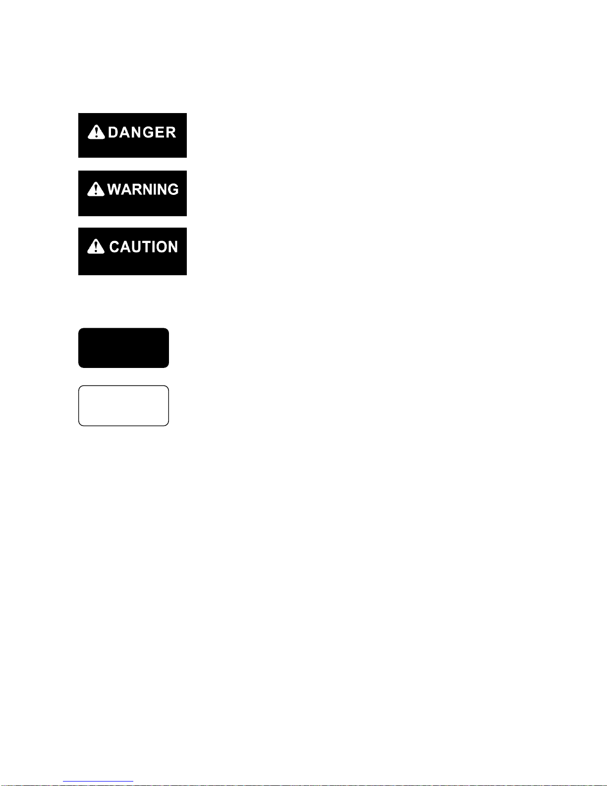
This manual classifies the risks into the following three categories to present the details of the safety
labels in easy-to-understand manner.
This denotes that there is an imminent hazard which will cause serious
personal injury or death.
The method of hazard circumvention is stated.
This denotes that there is a hazard which can cause serious personal injury
or death.
The method of hazard circumvention is stated.
This denotes that there is a potential hazard which may cause minor or
moderate personal injury or serious damage to this machine.
The method of hazard circumvention is stated.
This manual also provides the following to indicate what must be observed for the sake of the machine
and what will be of help.
This denotes that failure to handle the machine properly may damage the
machine or shorten its life.
This denotes helpful information.
Not only procedures for operation, inspection, and maintenance of this machine described in th is manual
but also safety precautions should pertain to the case where this machine is only used for specified tasks.
Every circumstance incidental to use of this machine is unforeseeable, and therefore, cautions given in
this manual and on this machine do not necessarily cover every safety-related issue.
Necessary safety actions should be taken under your responsibility if operation, inspection, and
maintenance in a situation that is not described in this manual are performed.
Even in the above case, never attempt the works and operations this manual prohibits you to do.
CAUTION
NOTES
Page 12
1-4
3. MACHINE OVERVIEW
3.1 SPECIFIED OPERATIONS
This machine is to be used for operation listed below.
• Crane operation
This machine is a mobile crane with a rubber track traveling dolly (carrier) mounted with a boom crane.
This self-propelled crane is capable of moving (traveling) in the worksite and craning an object weighing
within the rated total load.
This is also a remote-controlled crane.
3.2 MACHINE CONFIGURATION
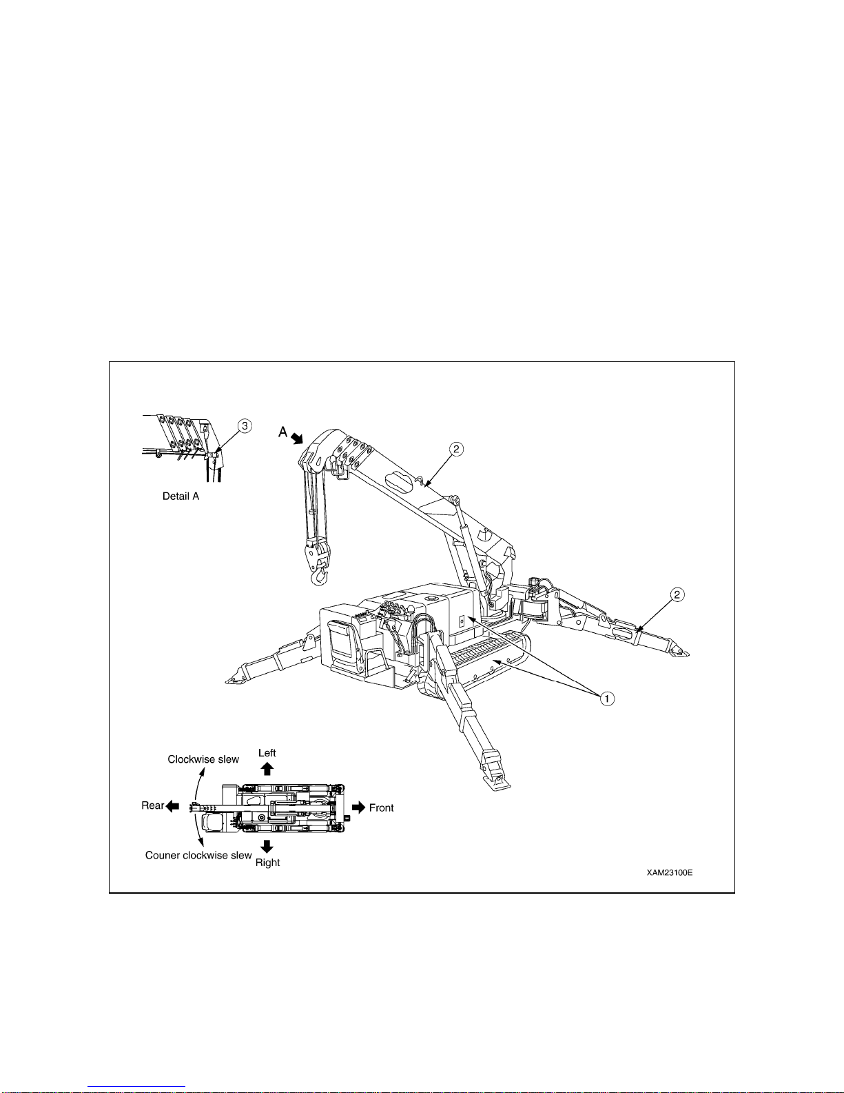
(1) Traveling dolly
(2) Crane
(3) Safety device
Viewed from the operation seat, the front, back, left, and right of the
machine are determined in this manual, viewing in the traveling
direction (front) of the machine.
Boom slewing motion is determined with the machine viewed from
immediately above; slew clockwise denotes r ight-handed motion and
slew counterclockwise denotes left-handed motion.
EXTERNAL VIEW
Page 13

1-5
This machine is composed of the units listed below.
[1] TRAVELING DOLLY
This is composed of a traveling gear, engine, traveling operation unit, and crane operation unit.
[2] CRANE
This is composed of a telescoping system, derrick system, hook block, winch system, and outrigger
system.
[3] SAFETY DEVICE
This is composed of the following parts and devices: Over hoist detector / automatic stop device,
three-winding stop alarm / automatic stop device, load indicator, hydraulic safety valve, hydraulic
automatic locking device, slinging rope detachment protector, alarm buzzer, audio alarm, level, crane
tip-over alarm (an alarm issued in the event of the crane opera tion at 3-degr ee in clination and trave ling at
15-degree inclination), traveling lever lock, traveling/crane/outrigger selector switch (designed to prevent
the machine from craning at traveling), outrigger safety device (outrigger interlock and crane interlock),
moment limiter (working envelope limited), working status lamp, outrigger non-installation warning lamp.
3.3 MACHINE FUNCTIONS
[1] TRAVELING DOLLY
• This is a compact machine designed to keep the overall width between the crane and outrigger
minimized with them housed (in traveling position).
This compact design is ideal for work in confined areas.
• Two-traveling lever operation enables not only direction changes among forward, backward, and
right/left but pivot turn and spin turn.
[2] CRANE
• An automatic slide outrigger is embedded in the cr ane to per mit outr igger extension and g rounding from
the operation seat.
• Through the combined use of telescoping, derricking, and slewing besides winch system operation, the
crane is capable of raising or lowering the hook block and moving an object weighing within the rated
total load to a designated position within the con fin es of the working envelop e.
• Remote-control units allow remote outrigger setting and remote crane operation.
Page 14

1-6
4. QUALIFICATION FOR OPERATION
• A high incidence of occupati onal accidents in crane operation has been reported.
Be aware that experienced engineers are also no exception.
• Warnings and precautions defined in this manual shall be observed for safety assurance
during operation of the machine.
4.1 QUALIFICATION FOR CRANE OPERATION
Only personnel that have obtained the license stipulated by laws and regulations applicable to the place of
use are qualified to operate this machine.
Contact the relevant government office or our sales service agency for further information.
Page 15
1-7
5. TERMINOLOGY
5.1 DEFINITIONS OF TERMS
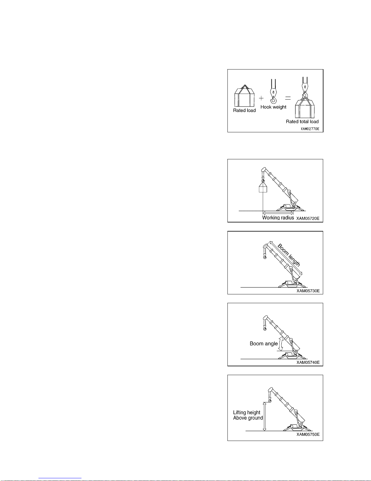
[1] RATED TOTAL LOAD
This is the maximum load that can be applied according to a boom
length and angle. The load includes the mass (weight) of hoisting
accessories (hooks) and slinging ropes.
[2] RATED LOAD
This is a load derived by subtracting the mass (weight) of hoisting
accessories (hooks) and slinging ropes from the rated total load,
which is a withstand load for hoisting.
[3] WORKING RADIUS
This is a horizontal distance between the axis of slewing and the
hook center.
[4] BOOM LENGTH
This is a distance between the boom primary pin and the sheave
pin of the end boom.
[5] BOOM ANGLE
This is an angle which the boom forms with the horizon.
[6] LIFTING HEIGHT ABOVE GROUND
This is a vertical distance between the hook bottom and the ground
with the hook raised until the upper limit.
Page 16
1-8
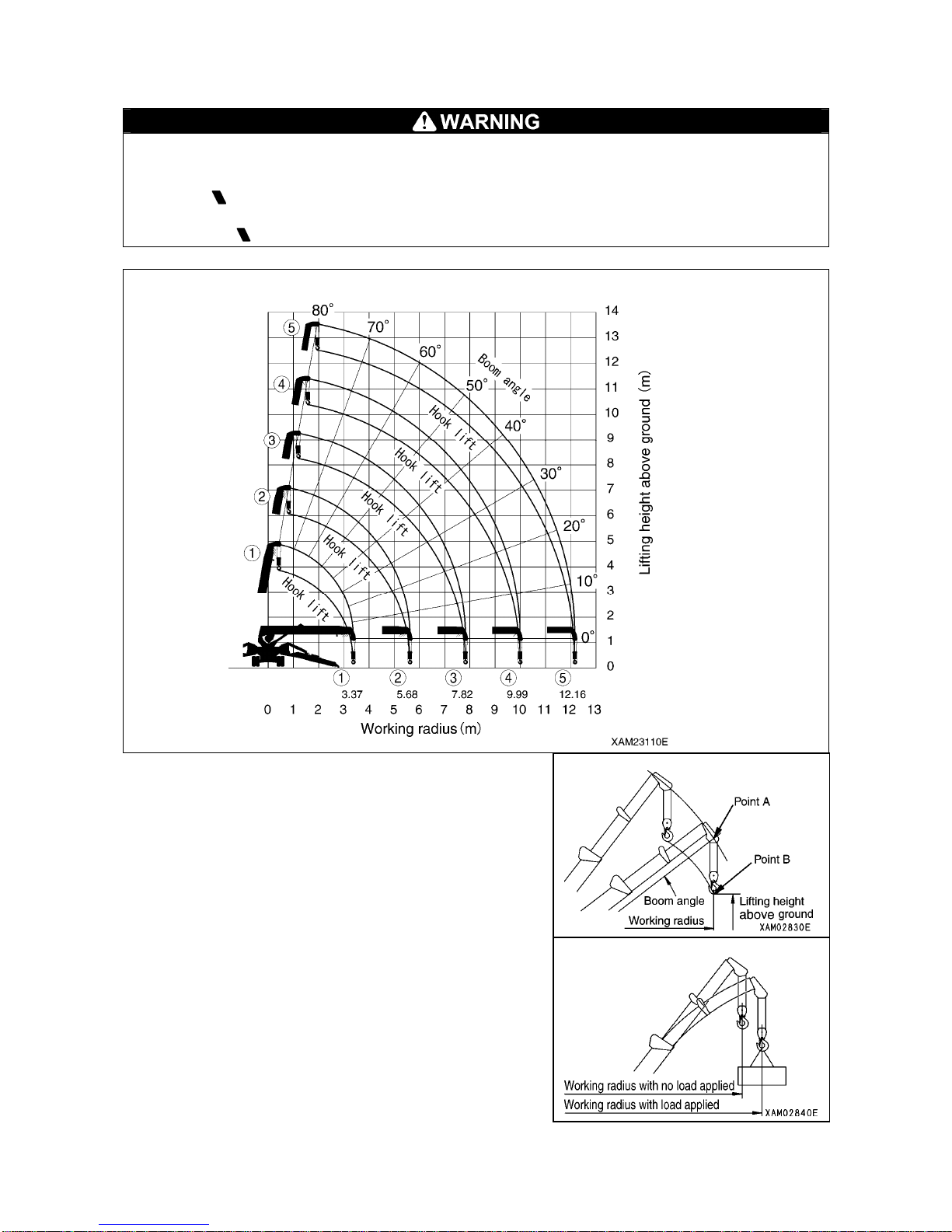
5.2 DIAGRAM OF WORKING RADIUS AND LIFTING HEIGHT
・ The working radius/lifting heig ht d iagra m indic ates t he re la tion between the working radius,
boom angle and lifting height above ground of this machine, without any load suspended.
・ “5.575m Boom” in the working ra dius/lifting he ight diagram shows the stat us where one half
of first
mark is extended from the second stage boom.
・ “7.075m Boom” in the working ra dius/lifting he ight diagram shows the stat us where one half
of second mark is extended from the second stage boom.
1. Point A denotes a boom angle and point B denotes a lifting
height above ground in the figure at right.
The same working radius is applied to points A and B.
2. The “diagram of working radius and lifting height” show s the
relationships the working radius, boom angle, and lifting
height at no load, allowing for no deflection in the boom.
A deflection occurs in the boom when an object is hoisted,
which causes the working radius to widen slightly.
The rated total load decreases with increase in the working
radius. Actual crane operation requires the planning of work,
allowing for sufficient clearance more than that provided in
the diagram.
Page 17
1-9
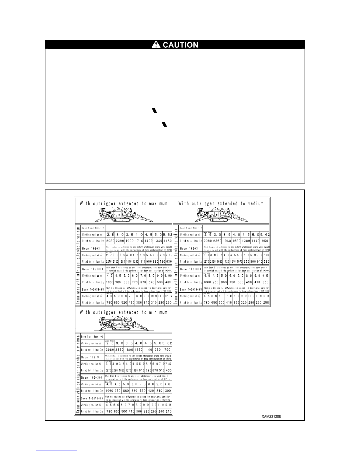
5.3 RATED TOTAL LOAD CHART
Rated total load chart is based on level , hard ground. D epending o n the outrig ger setting or
ground conditions, machine may tip over.
Rated total load chart is based on working radius with bending of boom and lifted load
taken into consideration.
If boom e is extended to any extent, work shoul d be per form ed within the capacity for
“5.575m Boom”.
When more than one half of the fi rst
mark is exposed from the boom (2), work should be
carried out within the performance for the “7.075m Boom”.
When more than one half of the second
mark is exposed from boom (2), work should be
carried out within the performance for the “8.575m Boom”.
If working radius exceeds the value of Working Radi us column in the chart by any extent,
work should be performed within the rated t otal load i n the next co lumn of Wor king Radiu s.
Rated total load is shown with the mass of hook (20kg) included.
Unless outrigger is extended to maximum, work should be performed in accordance with
the “Rated Total Load Chart without extending outrigg er to max im u m”.
Page 18
1-10
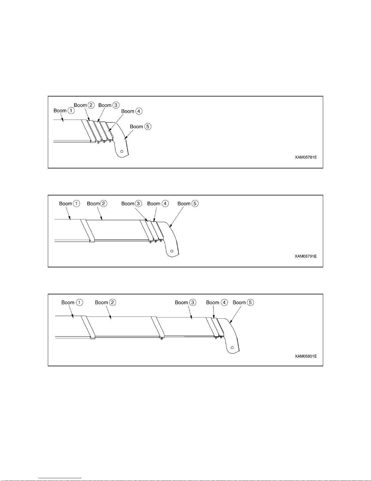
The rated total load chart provides the maximum loads that the crane is capable of hoisting objects in
parallel with the length of the boom. The loads are specified by working radius.
[1] BOOM LENGTH
The following figures illustrate the condition of the booms, “Boom (1)”, “Boom (1) + (2)”, “Bo om (1) + (2) +
(3)”, “Boom (1) + (2) + (3) + (4)”, and “Boom (1) + (2) + (3) + (4) +(5)” in the preceding boxes in the rated
total load chart.
1. “Boom (1)”: All the booms are retracted.
2. “Boom (1) + (2)”: With booms (3), (4), and (5) retracted, boom (2) is fully extended.
“Boom (1) + (2)” is to apply to crane operation with boom (2) extended even if only slightly.
3. “Boom (1) + (2) + (3)”: With booms (4) and (5) retracted, booms (2) and (3) are fully extended.
“Boom (1) + (2) + (3)” is to apply to crane operation with boom (3) extended even if only slightly.
Page 19
1-11
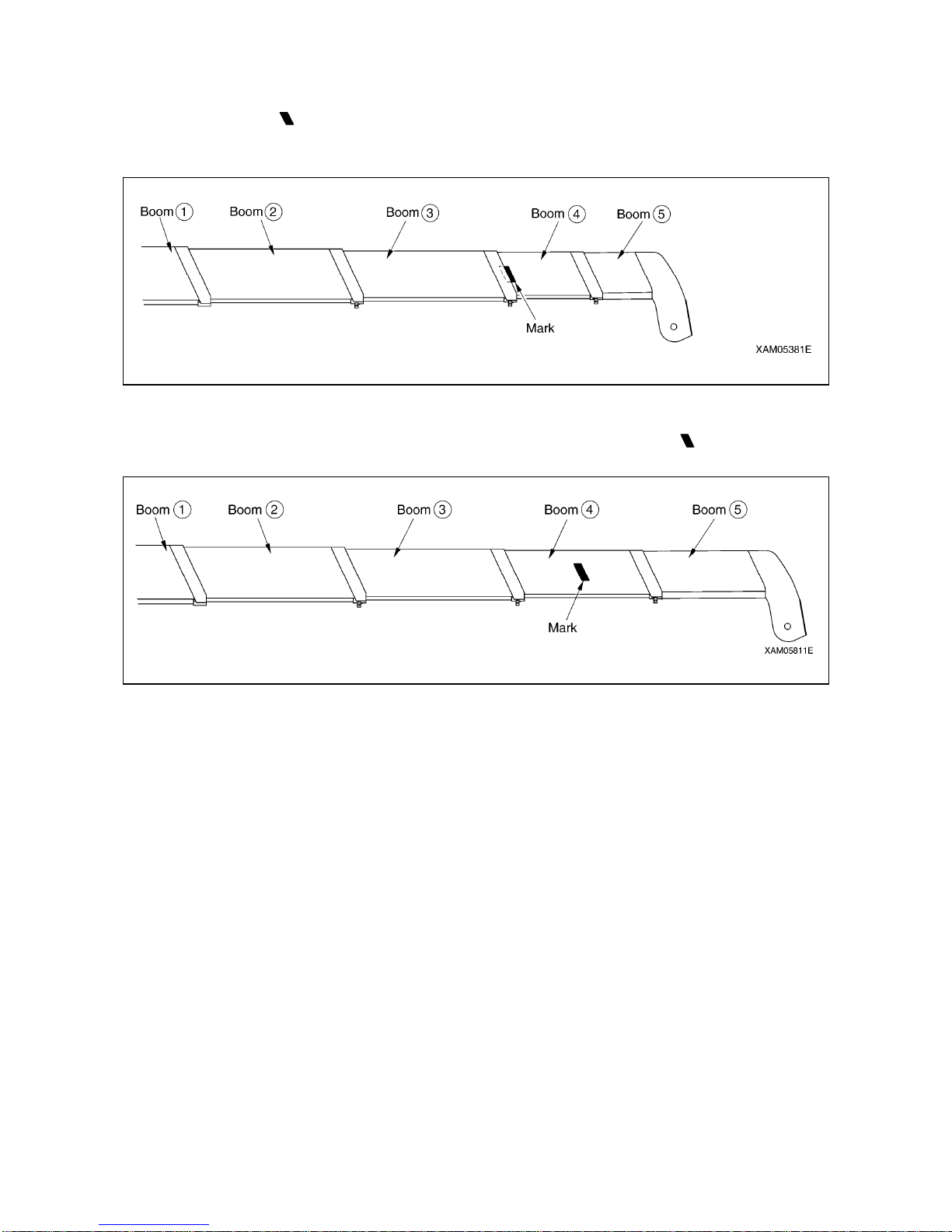
4. “Boom (1) + (2) + (3) + (4)”: With booms (2) and (3) fully extended, booms (4) and (5) are extended
midway (half of the “ mark” passes boom (3)).
“Boom (1) + (2) + (3) + (4)” is to apply to crane operation with booms (4) and (5) extended even if only
slightly.
5. “Boom (1) + (2) + (3) + (4) + (5)”: All the booms are fully extended.
“Boom (1) + (2) + (3) + (4) + (5)” is to apply to crane operation with half of the “ mark” on boom (4)
passes boom (3).
Page 20
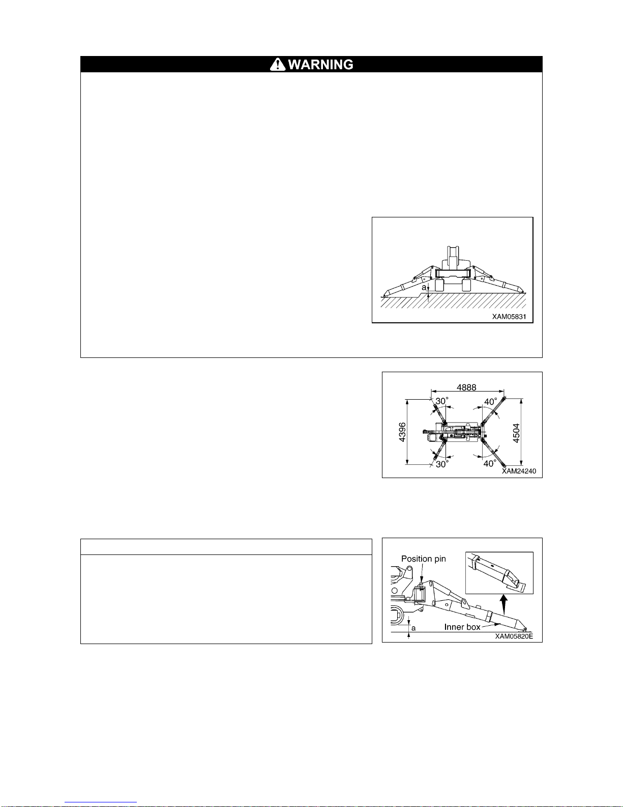
1-12
[2] OUTRIGGER MAXIMUM EXTENSION
• Make sure all the outriggers are placed properly before performing crane operation.
This machine features a safety-interlock system that prevents crane operation unless all the
lamps, other than the boom retraction lamp on the outrigger monitor, are on.
• Always place the machine in a horizontal pos ition with the use of the level when extending the
outriggers. A warning buzzer sounds when the machine is inclined 3° or more and stops when
the machine is placed in a horizontal position.
• When the crane is used with the outriggers extended other than at the maximum, crane
operation should proceed with respect to the values specified in the rated total load chart
corresponding to “When the crane is used with the outriggers extended at the
minimum/midway”.
Failure to perform crane operation with proper values may cause the machine to topple over.
Exercise caution when performing operation.
• Despite the maximum extension of all the outriggers, the
width of extended outriggers decreases due to an
ungraded ground even when clearance "a" in the right
figure is 50 mm.
Crane operation should proceed with respect to the
values specified in “When the crane is used with the
outriggers extended midway” in the rated total load
chart.
• The machine becomes unsteady at some point if it
undergoes a 360-degree slewing with an object hoisted.
Irrespective of the rated total load, ensure operation in a
short working radius and at low speed.
The figure shown at right represents the condition “When the crane
is used with the outriggers extended at the maximum” in the rated
total load chart.
Ensure that all the lamps, other than the boom retraction lamp on
the outrigger monitor, are on.
If the inner box is retracted even if only slightly, crane operation
should proceed with respect to the values specified in the rated
total load chart corresponding to “When the crane is used with the
outriggers extended at the minimum/midway”.
See "OPERATION 2.14 OUTRIGGER SETTING OPERATIO N” for
proper setting of the outriggers.
NOTES
Outrigger maximum extension is defined as that:
1. The outrigger is set at the positioning pin position (40° front,
30° back).
2. The inner box of all the outriggers is extended fully.
3. All the outriggers are placed on a level surface.
4. Approx. 50mm is assured for clearance "a” (between the
outrigger bottom and crawler bottom) in the figure at right.
Page 21
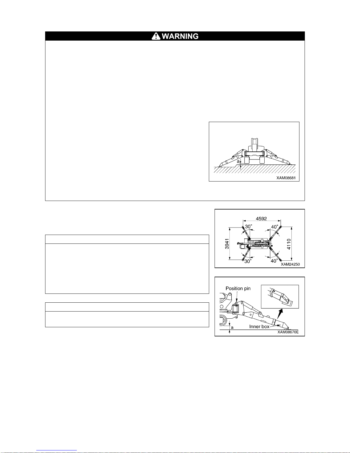
1-13
[3] OUTRIGGER MIDWAY EXTENSION
• Make sure all the outriggers are placed properly before performing crane operation.
This machine features a safety-interlock system that prevents crane operation unless all the
lamps, other than the boom retraction lamp on the outrigger monitor, are on.
• Always place the machine in a horizontal position with the use of the level when extending the
outriggers. A warning buzzer sounds when the machine is inclined 3° or more and stops when
the machine is placed in a horizontal position.
• When the crane is used with the outriggers extended other than at the maximum, crane
operation should proceed with respect to the values specified in the rated total load chart
corresponding to “When the crane is used with the outriggers extended at the
minimum/midway”.
Failure to perform crane operation with proper values may cause the machine to topple over.
Exercise caution when performing operation.
• Despite the midway extension of all the outriggers, the
width of extended outriggers decreases due to an
ungraded ground even when clearance "a" in the right
figure is 50 mm.
Crane operation should proceed with respect to the
values specified in “When the crane is used with the
outriggers extended at the minimum” in the rated total
load chart.
• The machine becomes unsteady at some point if it
undergoes a 360-degree slewing with an object hoisted.
Irrespective of the rated total load, ensure operation in a
short working radius and at low speed.
The figure shown at right represents the condition “When the
crane is used with the outriggers extended midway” in the rated
total load chart.
NOTES
Outrigger midway extension is defined as that:
1. The outrigger is set at the positioning p in position (40° front,
30° back).
2. The inner box of all the outriggers is extended midway.
3. All the outriggers are placed on a level surface.
4. Approx. 50mm is assured for clearance “a” (between the
outrigger bottom and crawler bottom) in the figure at right.
NOTES
If even a group of outriggers is retracted to a midway point, all
the outriggers are deemed to be extended midway.
Page 22
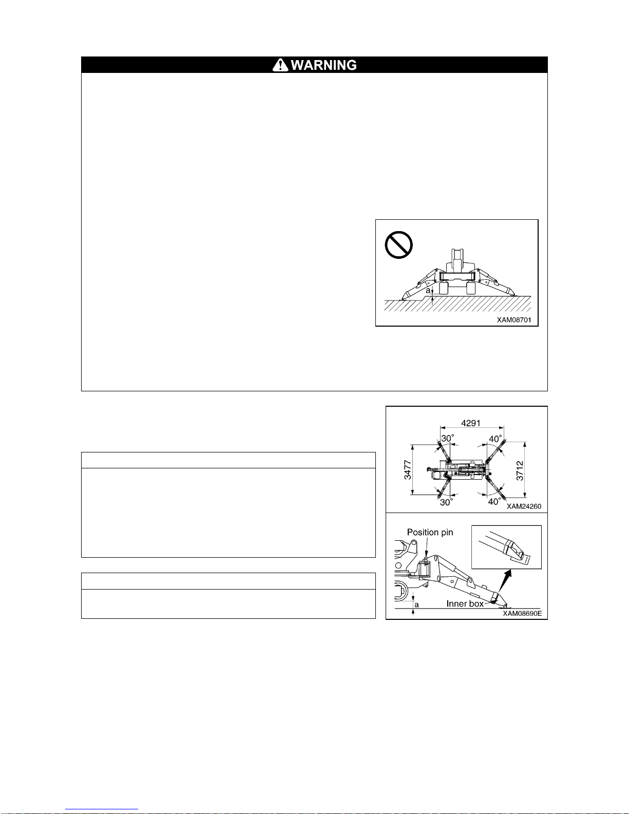
1-14
[4] OUTRIGGER MINIMUM EXTENSION
• Make sure all the outriggers are extended before performing crane operation. Crane operation
is allowed only when all the outriggers are placed properly. Potential overturning of the
machine may occur that leads to serious personal injury if disregarded.
• Always place the machine in a horizontal position with the use of the level when extending the
outriggers.
A warning buzzer sounds when the machine is inclined 3° or more and stops when the
machine is placed in a horizontal position.
• When the crane is used with the outriggers extended other than at the maximum, crane
operation should proceed with respect to the values specified in the rated total load chart
corresponding to “When the crane is used with the outriggers extended at the
minimum/midway”. Failure to perform crane operation with proper values may cause the
machine to topple over. Exercise caution when performing operation.
• Crane operation with the outriggers extended at the
minimum is permitted only if the outriggers are pl aced
on a level surface. 50mm of dimension between the
outrigger bottom and crawler bottom should be
obtained.
• On ungraded ground or similar, the width of extended
outriggers decreases even when clearance "a" in the
right figure is 50 mm. Do not perform crane operation
under such extension condition. Potential overturning of
the machine may occur that leads to serious personal
injury if disregarded.
• The machine becomes unste ady at some point if it undergoes a 360-deg ree slewing with an
object hoisted. Irrespective of the rated total load, ensure operation in a short working radius
and at low speed.
The figure shown at right represents the condition “When the crane
is used with the outriggers extended at the minimum” in the rated
total load chart.
NOTES
Outrigger minimum extension is defined as that:
1. The outrigger is set at the positioning pin position (40° front,
30° back).
2. The inner box of all the outriggers is minimized.
3. All the outriggers are placed on a level surface.
4. Approx. 50mm is assured for clearance "a” (between the
outrigger bottom and crawler bottom) in the figure at right.
NOTES
If even a group of outriggers is retracted to the minimum point, all
the outriggers are deemed to be extended at the minimum.
Page 23
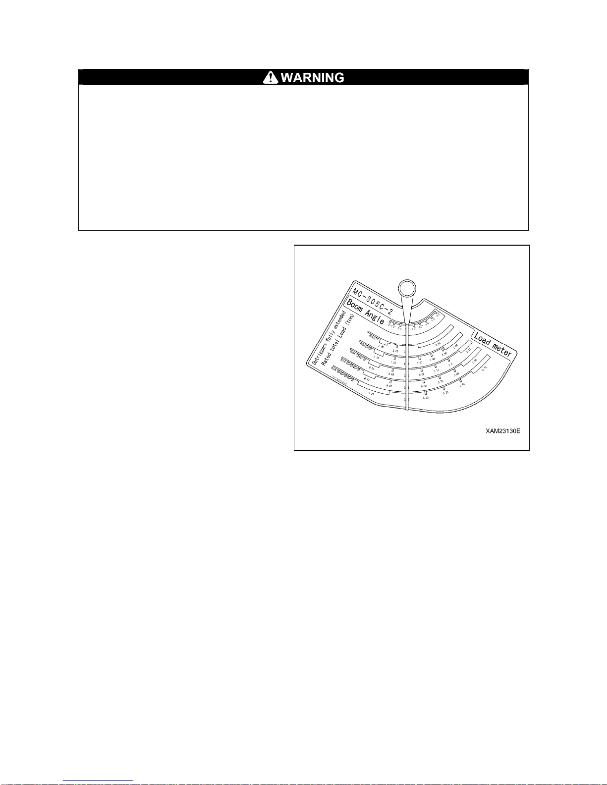
1-15
5.4 LOAD INDICATOR
• The following precautions should always be observed when reading the “rated total load”
provided by the load indicator. Potential overturning or damage to the machine may occur that
leads to a serious accident if disregarded.
1. The outriggers should be placed on a level and firm surface.
2. The outriggers should be extended at the maximum.
• The weight of an object including that of a hoisting accessory and slinging rope must remain
below the rated total load for hoisting objects. With the boom length (number of stages) and
angle specified, make a comparison between the rated total load provided by the load
indicator and the weight of the object.
• The rated total loads provided b y the load indicator are not avai lable if the outri ggers are not
extended at the maximum.
Only read the “boom angle" on the load indicator.
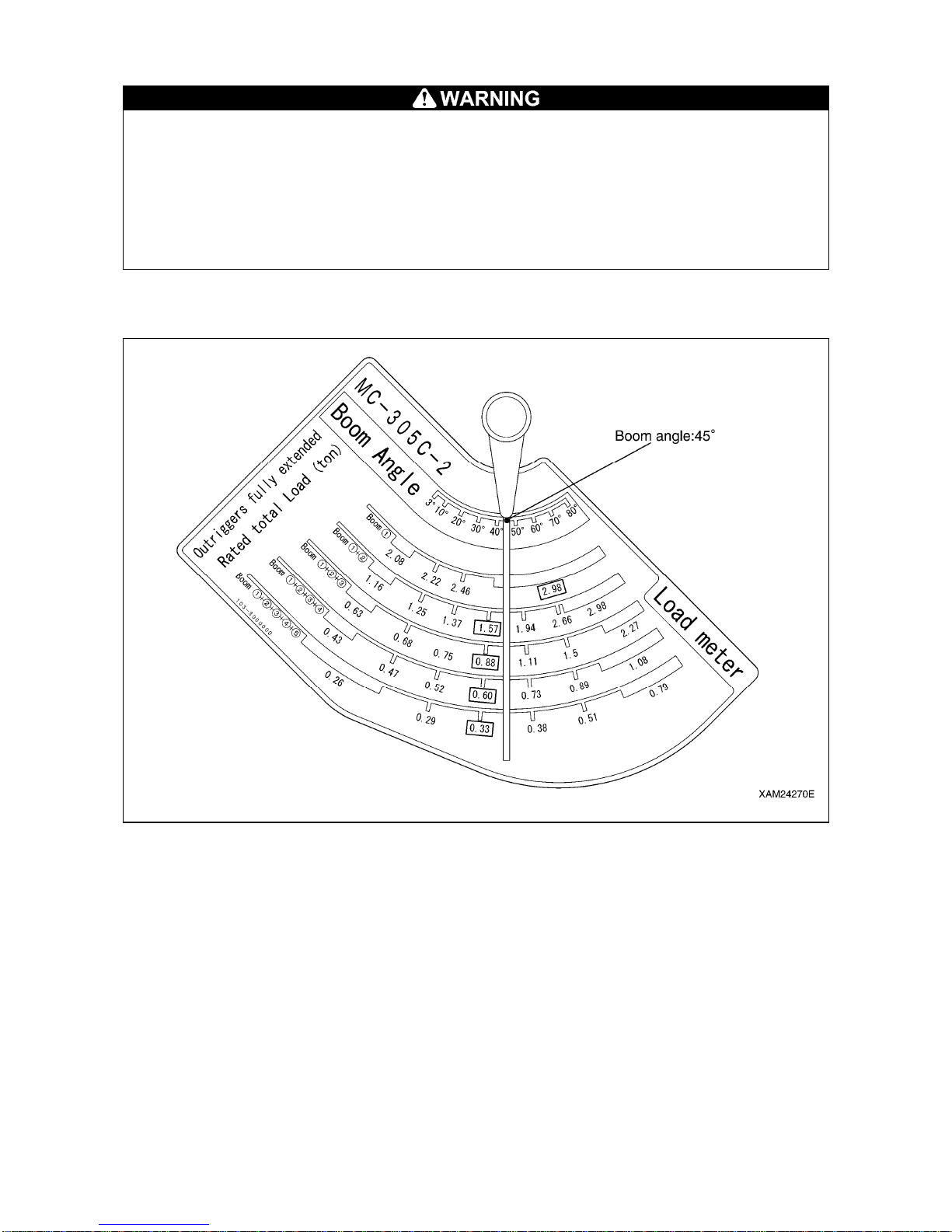
The load indicator, com pose d of a “pointe r” and
“scale plate” as shown at right, is attached to
both sides of boom 1.
The load indicator shown at right provides
readouts on the rated total load under the
following conditions: that the outriggers are
placed on a level and firm surface, that the
outriggers are extended fully (see section 5.3
“[2] Outrigger maximum extension” in
Introduction), and that no deflection is
developed in the boom.
How to read the load indicator:
• Read an intersection point of the scale plate
and the pointer of the boom.
The value read is a rated total load on the
relevant boom.
Page 24
1-16
[An example of observation]
• The following precautions should always be observed when reading the "rated total load"
provided by the load indicator. Potential overturning or damage to the machine may occur that
leads to a serious accident if disregarded.
1. The outriggers should be placed on a level and firm surface.
2. The outriggers should be extended at the maximum.
• The rated total loads provided b y the load indicator are not avai lable if the outri ggers are not
extended at the maximum.
Only read the "boom angle" on the load indicator.
This explanation of the observation assumes the case when the load indicator is showing the following
condition.
1. Boom angle
The boom angle is approximately 45 degrees.
2. Rated total load when outriggers are fully extended
2.98 t if boom (1).
1.57 t if booms (1) + (2).
0.88 t if booms (1) + (2) + (3).
0.60 t if booms (1) + (2) + (3) + (4).
0.33 t if booms (1) + (2) + (3) + (4) + (5).
Page 25

2-1
SAFETY
1. BASIC PRECAUTIONS 2- 2
2. DRIVING RELATED PRECAUTIONS 2- 7
3. TRANSPORT PRECAUTIONS 2-21
4. BATTERY HANDLING PRECAUTIONS 2-23
5. MAINTENANCE PRECAUTIONS 2-25
6. SAFETY LABEL LOCATIONS 2-32
7. WEEE DIRECTIVE LABEL LOCATIONS 2-42
All the safety precautions defined in this manual should
always be read and observed.
Failure to follow the safety precautions can cause serious
personal injury or death.
Page 26
2-2
1. BASIC PRECAUTIONS
OBSERVE THE MANUAL AND SAFETY LABELS
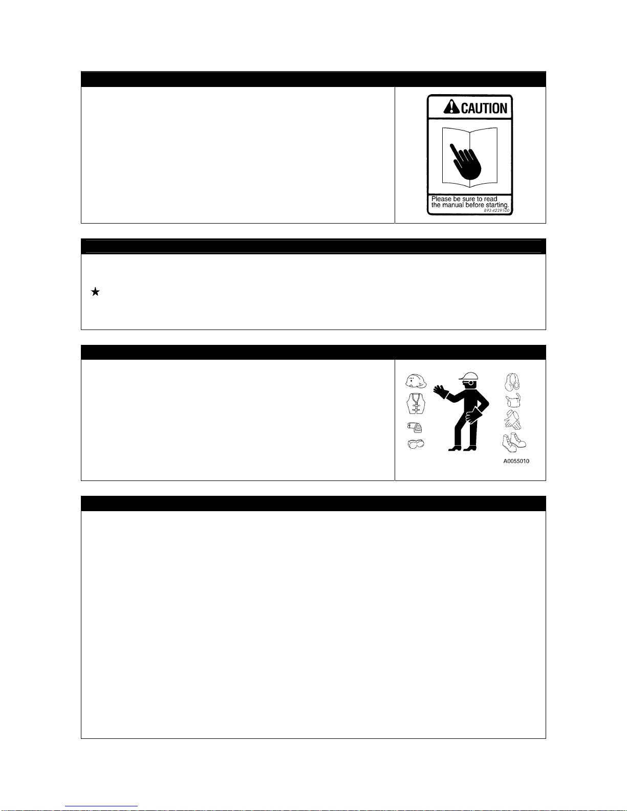
• Read well and understand this manual as well as the safety labels
labeled on various part of this Machine. Attempt to drive/operate
without understanding fully may result in wrong operation that may
cause personal or equipment accidents.
• Fully understand the proper use and inspection/maintenance
procedures, and exercise safe works.
• Make sure this manual and the safety labe ls labeled on variou s part
of this Machine are legible all the time.
Whenever illegibility or loss occurs, order us or our sales service
agency and put the safety label back to the original location.
DRIVING LICENSE
• Licenses are necessary to drive this Machine.
Always obtain licenses before driving.
See “Introduction 4. Qualification for Operation” for details
• The drivers are requested to receive educations and training of the handling methods and other
subjects in the applicable office, and obtain sufficient driving operation skill before work.
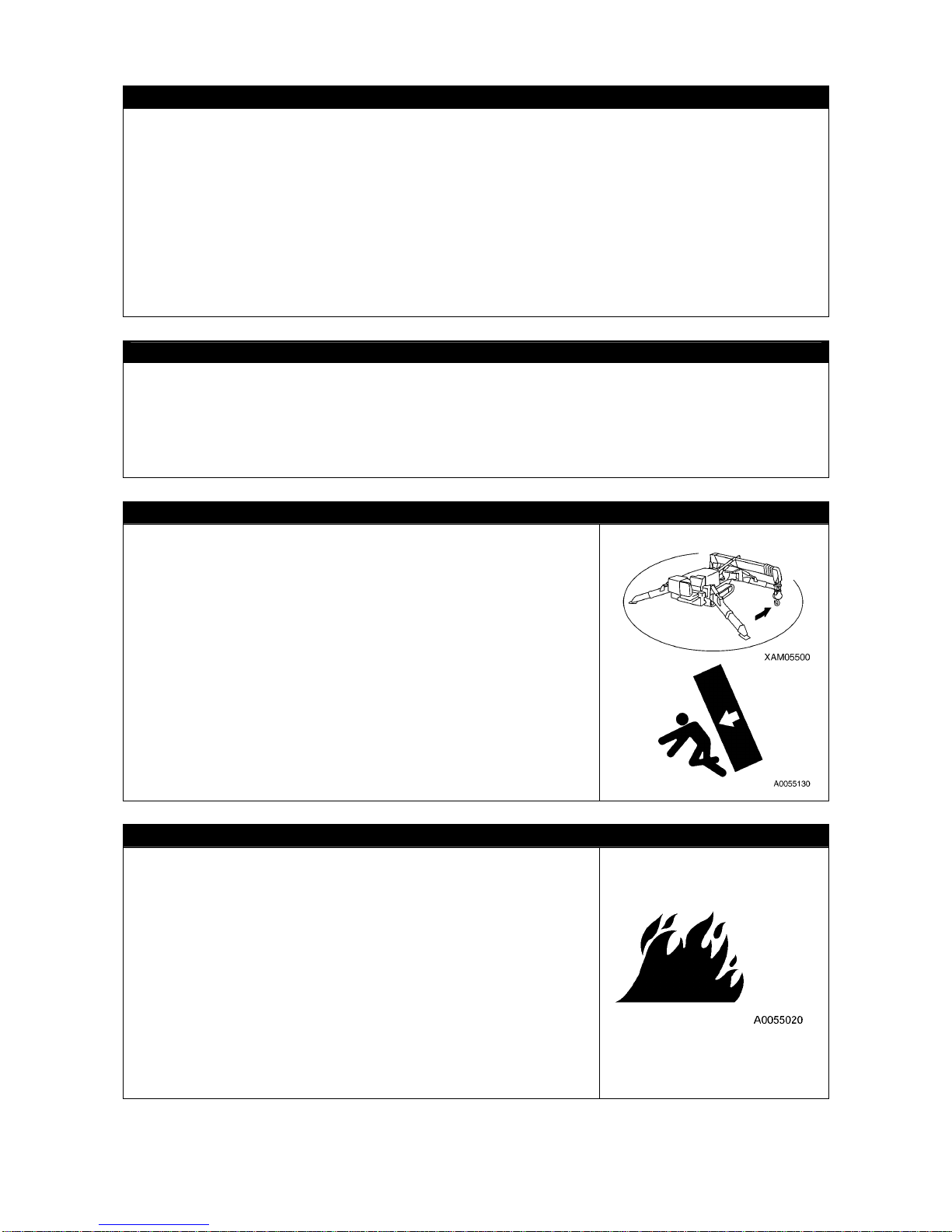
WEAR PROTECTIVE EQUIPMENT AND CLOTHES SUITABLE FOR WORK
• Always put on a helmet, safety shoes and safety belt.
• Select and make sure to put on necessary protective equipment
suitable for the relevant working condition.
• Do not wear loose garment or accessory item that may catch
operation lever or protrusions and cause unexpected movement of
the Machine.
COMMIT TO SAFE OPERATION
•Obey the instructions and signs given by the manager and work supervisor, and observe safety first
during the work.
• Obey the crane work basics during work.
• Before starting driving or a work, always carry out the inspections before work.
• Do not work under bad weather for instance strong wind, thunder or mist.
• Do not drive under any condition when you are o vertired, do sed with a lcoh ol o r af ter ta king a so mnific
drug.
• Obey all of the workplace rules, safety regulations and operation method sequences during driving
operations and inspection/maintenance.
• Pay attention to surrounding conditions and pedestrians all the time when driving or working.
Whenever pedestrian approaches unwarily, abort working on ce, and take a measure such as issuing a
warning.
• When driving, be mentally prepared for unexpected situation and so that you can take measures
immediately.
• Do not attempt any use out of the capabilities and purposes described in this manual under any
circumstance.
• Observe the designated rated total load and work range when driving.
• Do not attempt inattentive driving, harsh driving or awkward operation under any circumstance.
• Pull out the key when leaving operation seat.
Page 27
2-3
USE OF MACHINE THAT WAS RENTED OR PREVIOUSLY USED BY SOMEONE ELSE
Check the following subjects on writing before using any Mach ine that was rented or previously used by
someone else.
In addition, check the inspection record table for the maintenance conditions such as the periodic
inspections.
(1) Crane capacity
(2) Crane maintenance condition
(3) Behavior and disadvantage unique to the crane
(4) Other subjects that require attention when driving
(a) operating condition of the brakes, crutches and others
(b) Presence/absence and lighting condition checkup of lightings and rotating lamps
(c) Operation condition of hook, winches, boom, outriggers and related
PROVIDE SAFETY DEVICES FOR SURE
• Check that all guards and covers are attached properly. Repair immediately if damaged.
• Understand how to use the safety devices well and use properly.
• Do not detach any safety device under any circumstance. Keep control to achieve proper function all
the time.
• Improper use of safety device leads to serious bodily accidents.
• Do not trust safety device too much to operate.
FOLLOW INSTRUCTIONS AND SIGNS WHEN WORKING
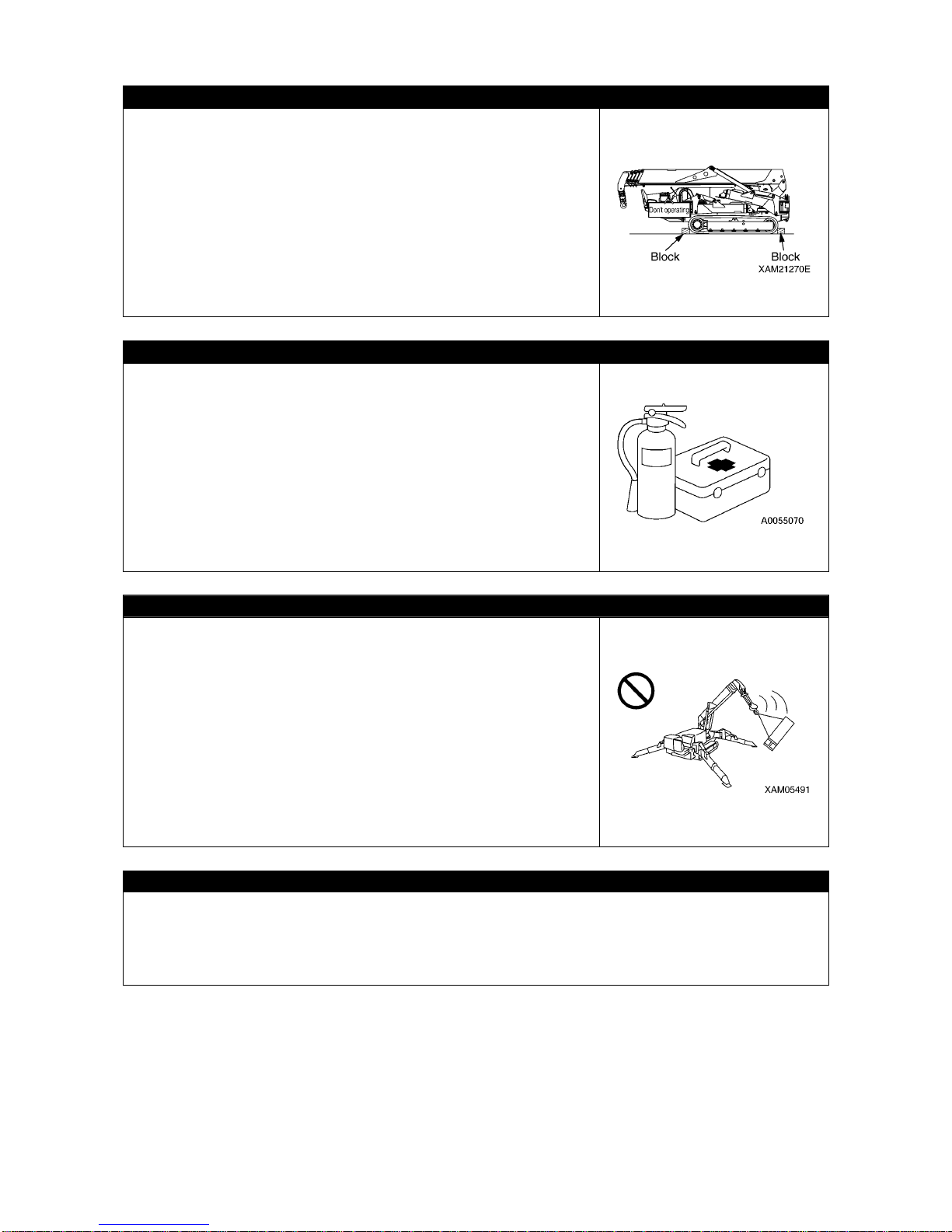
• When working with the crane, appo int a work supervisor and mutual
signs beforehand, and follow the work supervisor and signs during
work.
• When working at a location where many parts are unsealed from
the driver, be especially careful to follow the instructions and signs
of the work supervisor and pay attention when driving.
• When working with the crane, the clea rance between th e boom and
the traveling dolly and also the gaps between the movable parts of
the derrick cylinder may catch body parts such as an arm or finger.
The driver is requested to make sure no one is within the working
radius of the crane before operating crane.
PREPARE FOR ABNORMALITY
• Carry out secure inspections and services, and be careful to
prevent accident before happening.
• Whenever you feel abnormality of the Machine, abort working
immediately, ensure safety and report to the manager.
• Assign in advance who takes which solution to prevent secondary
accident.
• Do not drive the Machine when fuel or hydraulic oil is leaking from
the Machine. Report the manager what is the abnormality, and fully
repair the fuel/hydraulic oil before use.
The fuel for this Machine is light petroleum. Be especially careful for
presence of fuel leak.
• Before leaving the Machine, lower the hoisted load to the ground,
stop the engine and pull out the engine key.
Page 28
2-4
TEMPORARY STORAGE WHEN ABNORMALITY IS FOUND WITH MACHINE
In case the Machine is found with abnormality and is therefore stored
temporarily waiting for service, apply following measures to notify all
persons in the office that the use is prohibited due to failure.
• Indicate warning tags on the crane operation lever and other
applicable parts.
Write clearly the information such as abnormality contents, name
and contact of the storage manager, and the term of storage.
• Keep immovable when parking by for instance putting the blocks on
the rubber tracks as pawls.
• Pull out the engine key and bring with you.
PROVISION OF FIRE EXTINGUISHER AND FIRST AID BOX
Always observe followings to prepare for injuries and fires.
• To prepare for fires, decide the fire extinguisher storage location
and install one, fully read the attached label for the usage and be
prepared for fighting against the emergencies.
• Decide the location to store the first aid box. In addition, inspect the
first aid box periodically and replenish the contents as necessary.
• Decide the measures to take upon an injury or fire accident.
• Decide how to contact the emergency address (for instance the
emergency physician, ambulance or fire departmen t), and show the
contact address at designated position so any person can make th e
contact.
DO NOT RUSH AND BE CAREFUL WHEN WORKING
• Do not attempt sudden lever operation or harsh driving.
• When two or more cranes work close to each other, drive carefully
while paying attention to accidents such as trips caused by
contacting each other. Also, appoint a guide if necessary for
increased prevention of contact accidents.
• When abnormality or danger occurs during work, abort working
immediately to avoid hazard.
• Abort the work under bad weather (heavy rain, strong wind,
thunder, thick fog).
Decide whether to abort working by seeing the "work abort de cisio n
standard" in the work schedule and by discretion of the work
supervisor of the site.
DO NOT MODIFY
Do not modify the Machine without our written consent under any circumstance.
The modification raises a safety issue, so consult us or our sales service agency beforehand.
We cannot be held responsible for any bodily accident or failure caused by modification that was
performed without consulting us.
Page 29
2-5
SAFETY WHEN REFILLING FUEL
• Light petroleum is used as the fuel of this Machine.
Do not refill wrong kind of fuel.
Refilling wrong oil may damage the engine.
• Always stop the engine before refilling fuel.
Refilling the oil when engine is driving may cause leaked fuel to
draw fire from hot muffler or other substance.
• Oversupply of oil results in spilling and is dangerous. Refill slightly
fewer than the specified level.
Always wipe away cleanly whenever the fuel spills.
• Securely close the tank cap after replenishing fuel.
KEEP FIRE AWAY FROM OIL
Attempt to let a fire approach the fuel, hydraulic oil or engine oil may
result in catching fire. Strictly observe the followings.
• Do not let any fire such as a cigarette or match approach
combustibles.
• Securely close all of the fuel and oil container caps.
• Keep the fuel and oils in well-ventilated location.
• Store the fuel and oils in a fixed location and keep unrelated
persons away.
• Do not leave the site when replenishing the fuel or oil.
Be especially careful to observe "Safety when refilling fuel"
described earlier when replenishing oil.
• Cleanly wipe away fuel and oil that spilled during replenishment.
HANDLING HIGH TEMPERATURE
During short time after stopping operation of the Machine, the en gine
itself and engine oil, cooling water and hydraulic oil are in high
temperature, and in addition the pressure is accumulated inside the
hydraulic oil tank.
Attempt to inspect the engine, remove the radiator cap, drain oil,
drain water or replace the filter under such condition may result in
burns.
Wait until the temperature drops, then follow the following
sequences.
• To prevent emission of the high temperature oil, stop the engine
and wait until the oil temperature drops, and when loosening the
cap, turn slowly and relieve the pressure before detaching the cap.
(To find how much the oil temperature dropped, let your hand
approach the surface of the hydraulic oil tank or similar location
without actually contacting and find out from the ambient
temperature.)
Page 30
2-6
BEWARE OF ASBESTOS DUST
Inhalation air containing asbestos may result in lung cancer. This
Machine does not use any asbestos, but asbe stos may be containe d
in the wall, ceiling or other part of construction w ithin the wor k area of
this Machine. In addition, be careful of the followings when working
with a material that may be using asbestos.
• Put on designated dust free mask and/or other equipment as
necessary.
• Do not use compressed air for cleaning.
• Spray water when cleaning to prevent asbestos dusts from flying
into air.
• Always work at windward location when driving the Machine at a
site that may contain asbestos dusts.
• Strictly observe the assigned rules related to the working site and
environmental standard.
CRANE INJURY PREVENTION
Do not let whole or part of your body enter any of the following
clearances, since such act may cause serious bodily accidents.
• Between the boom and the traveling dolly.
• Between the outrigger support and the ground contact surface.
• Between the boom/post and the derrick cylinder.
• Between the winch drum and the wire ropes.
• Between sheaves and wire rope.
• Between the crawlers and the ground.
BEWARE OF EXHAUST GAS
When starting the engine or handling fuel/cleaning oil/paint indoors or
at a location with bad ventilation condition, prevent gas-poisoning risk
by improving the ventilation by opening the windows and exits.
If the ventilation is insufficient even after opening the windows and
exits, set up a ventilation fan.
Page 31
2-7
2. DRIVING RELATED PRECAUTIONS
2.1 BEFORE STARTING ENGINE
ESTABLISH SAFETY OF WORKING SITE
• Confirm that no danger is present at the working site before starting
work.
• Investigate the ground and road surface condition of the working
site and decide the best working method.
• Flatten the inclination of the working site as much as possible
before starting work. Also, if sands and gravels are excessive, spray
water before work.
• When working over the roadway, enforce keep out by for instance
placing guides or surrounding by barriers, and ensure the safety of
the traffic vehicles and pedestrians.
• Enforce keep out to prevent people from entering the working site
and apply measures to prevent people from approaching.
Attempt to approach moving Machine may result in hard collision by
contact or pinching, and may result in serious bodily accidents and
deaths.
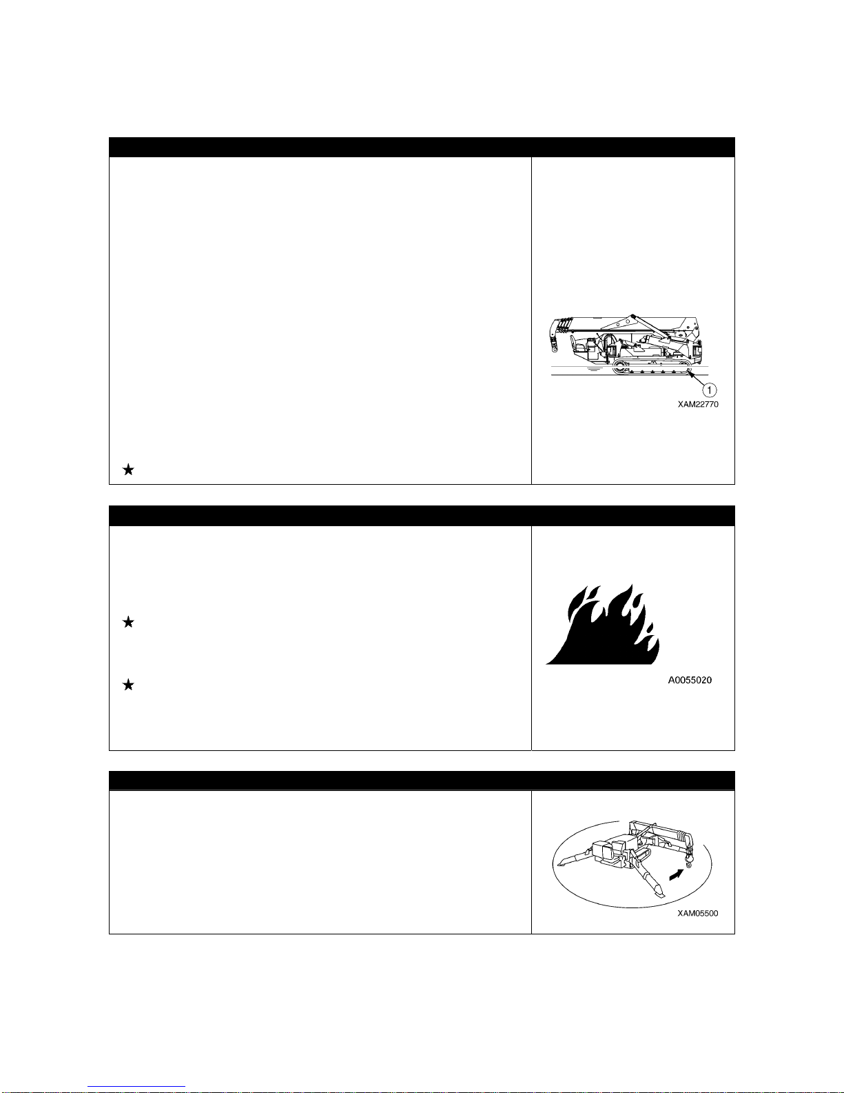
• When traveli ng in the wate r or crossing over shallow water, check
the ground condition, depth and water velocity beforehand and
make sure not to exceed the allowable water depth (no higher than
center of idler (1)).
See “Operation 2.12 [2] Allowable Water Depth” for details
INSPECTION BEFORE STARTING ENGINE
Execute following inspections before the first engine startup of the
day.
Omitting these inspections may result in serious bodily accidents.
• Inspect for the fuel/oil leak, accumulation of combustibles around
the engine and battery systems, and similar phenomenon.
See “Operation 2.1 Checking Before Operation” for details.
• Inspect the fuel quantity, cooling water quantity, hydraulic oil tank
quantity, air cleaner blockage, electrical wiring damage, and check
operations of safety devices and instruments.
See “Operation 2.1 Checking Before Operation” for details.
• Make sure the operation levers are at neutral position.
Check that the operation linkages operate adequately.
Always repair if any result of the above is faulty.
CAUTIONS WHEN STARTING ENGINE
• Make sure no person or object is within the boo m swing radiu s area
before starting engine.
• Blow the horn for warning before starting the engine.
• Do not start the engine by short-circuiting the starter circuit. Such
may cause a fire.
Page 32
2-8
2.2 AFTER STARTING ENGINE
INSPECTION AFTER STARTING ENGINE
Omitting the inspections after starting the engine results in delay to notice the Machine abnormalities,
and may result in bodily accidents and Machine damages.
Execute inspection in a wide location with no obstacle. In addition, be sure to prevent people from
approaching nearby the Machine.
• Inspect the equipment operation conditions, Machine traveling conditions, outrigger operation
conditions, winch winding up and down, boom derricking, and crane operation conditions such as
extension, retraction and swinging.
• Inspect the sound, vibration, heat and odor of the Ma chine , and che ck for instrument errors, a ir lea ks,
oil leaks, fuel leaks, water leaks and other bad factors. Be extra careful with fuel leaks.
• Always repair broken part whenever an abnormality is found.
Attempt to use without servicing may result in unexpected bodily accidents and/or Machine failures.
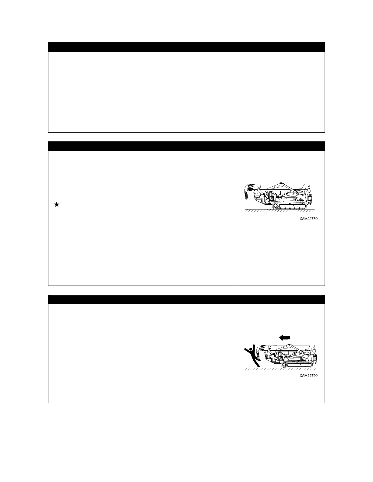
CAUTIONS WHEN STARTING TO MOVE MACHINE
To prevent serious injuries and death accidents, always execute the
followings before moving the Machine.
• Set the Machine to the traveling posture in the right diagram.
Do not travel when the hook block is not contained.
• Make the boom fully lowered and retracted.
• Fix the hook block to the containment position.
• Make the outrigger contained.
See “Operation 2.5 Machine Travel Posture” for details.
• Make sure again that no one or object is in the vicinity before
starting to move.
• Blow the horn for warning before starting to move .
• Always remain seated in the cab seat during traveling operation of
the Machine.
• The Machine is prohibited to travel when a person or load is on the
traveling dolly or the boom.
• When traveling, stow hook and outrigger, and make sure the
surrounding safety.
• When stowing outriggers, insert each position pins completely to
lock.
CAUTIONS WHEN MOVING FORWARD/BACKWARD OR CHANGING DIRECTION
Always observe followings to prevent serious injuries and deaths
when moving the Machine.
• Drop the speed early and wait until the Machine stops before
changing from forward to backward, or backward to forward.
• Blow the horn and alert to the people nearby before changing
between forward/backward movements or changing direction.
• Check that no one is around the Machine.
The front of the Machine frame requires special attention because
certain part of vision is blocked, so stop the Machine as necessary
and make sure no one is at front or around.
• Place a guide if the location is hazardous or with bad view.
• Make sure to prevent people from crossing the moving direction or
be at the direction to be changed.
Page 33
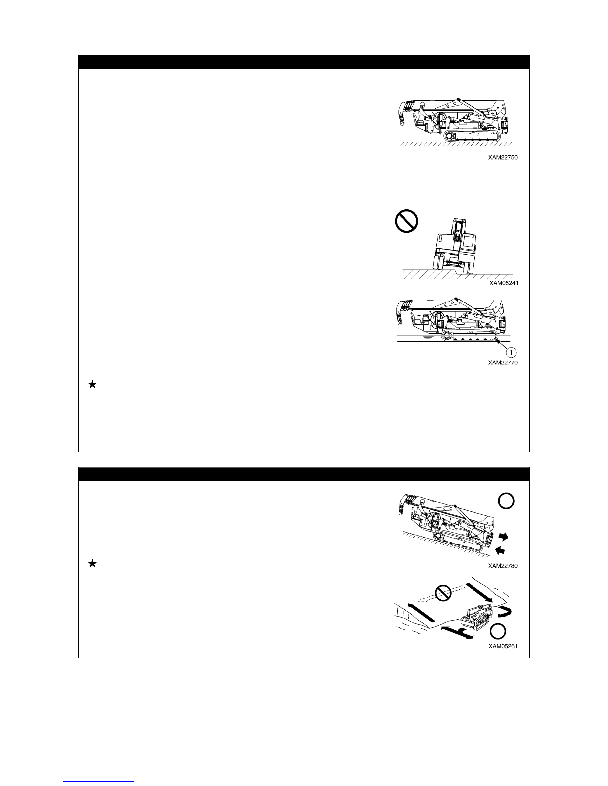
2-9
CAUTIONS WHEN TRAVELING
Always observe followings to prevent serious injuries and death
accidents when the Machine is traveling.
• Do not attempt looking sideways or other dangerous act when
driving.
• Do not over speed, start moving sudden, stop sudden, swing
sudden or meander since such acts are dangerous.
• ALWAYS remain seated in the cab seat when operating during
drive.
• Whenever you find a machine abnormality (sound, vibration, odor,
instrument error, fuel leak , wate r leak or o il leak ), immed iately p ark
the Machine in a safe location and inspect the cause.
• Do not operate to suddenly change the direction. Such may cause
the Machine to lose the balance or to damage the Machine or
nearby object.
• When traveling over uneven terrain, travel as slow as possible to
prevent tripping, and avoid acute operation when changing the
direction.
• Avoid moving over obstacles as much as possible.
Travel as slowly as possible when moving over an obstacle for
unavoidable reason. Also, do not move diagonally over obstacles
that cause the Machine to tilt excessively (10 degrees or more).
• When traveling, ensure extra clearance to prevent accident of
contacting other machinery or object.
• When traveli ng in the wate r or crossing over shallow water, check
the ground condition, depth and water velocity beforehand and
make sure not to exceed the allowable water depth (no higher than
center of idler (1)).
See “Operation 2.12 [2] Allowable Water Depth” for details.
• Check the withstand ability against the Machine mass before
crossing over a bridge or construction that is a private property. In
case of highway, ask the applicable road management
administration and follow the given advice.
• Do Not travel with load hoisted.
BE CAREFUL WHEN TRAVELING OVER SLOPE
ALWAYS observe followings to prevent serious injuries and death
accidents when traveling over a slope for unavoidable reason.
• Be careful of tripping and skids when traveling over slope.
• Do not change orientation on or horizontally when traveling over
slope. Practice safe traveling by for instance lowering to the plain
land and divert.
See “Operation 2.12 [3] Cautions on Upward/downward slope”
for details.
• Skids happen more than you think on grasses, fallen leave s, and on
wet steel plates.
Avoid the Machine from being horizontal over the slope as much as
possible, and decrease the speed sufficiently.
• Travel slowly by low speed when traveling downhill. In addition,
brake (by setting the travel lever to neutral) as necessary.
Page 34
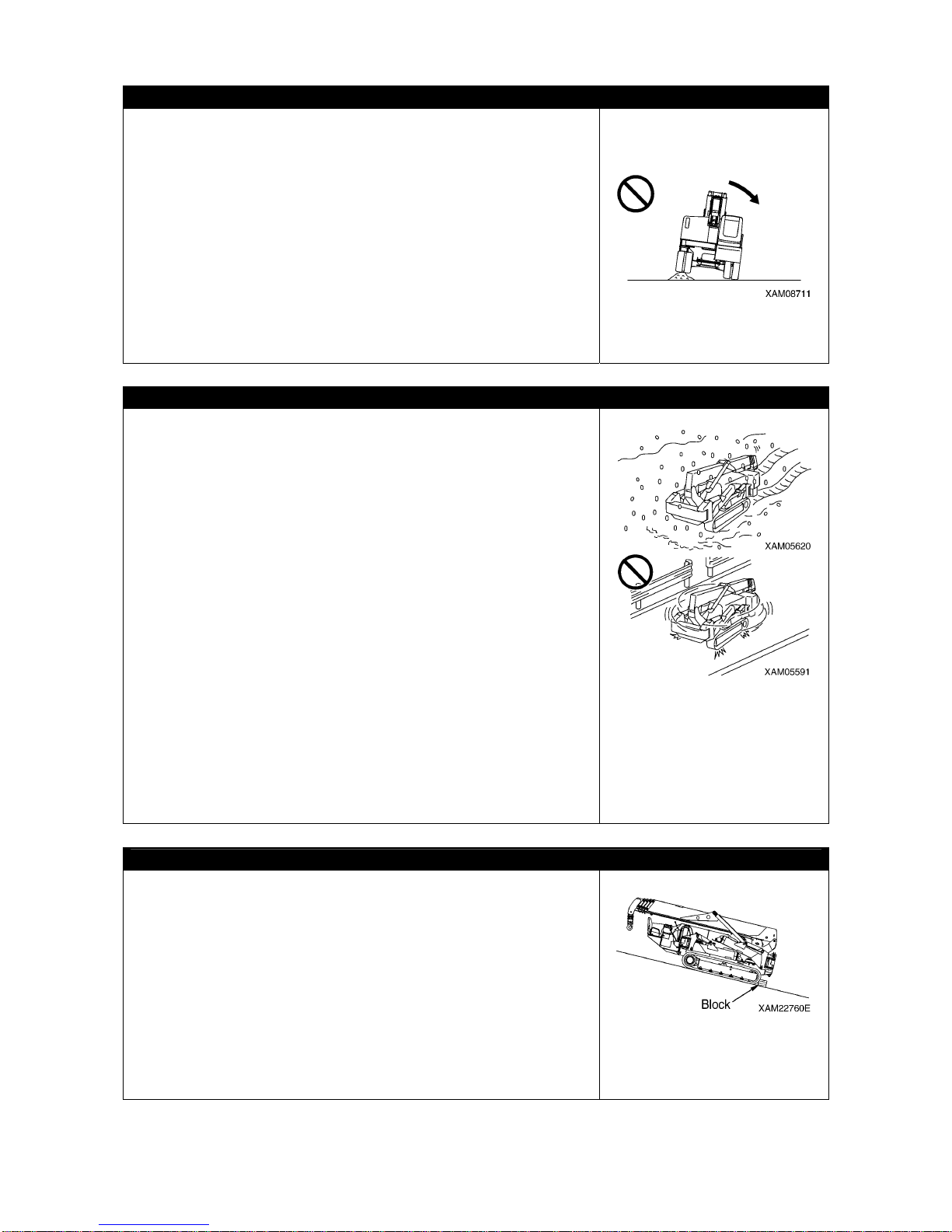
2-10
BE CAREFUL OF TRIPPING ON UNSTABLE GROUND
Always observe followings to prevent serious injuries and death
accidents when traveling over an unstable ground for unavoidable
reason.
• Do not enter soft ground area. The Machine is difficult to evacuate
from such area.
• The ground near cliff, roadside and deep gully is unstable, so av oid
going near such ground as much as possible.
The Machine may trip or fall when the ground loosens due to mass
and/or vibration of the Machine. Be especially careful that the
ground is likely loosen after rain, use of dynamite or earthquake.
• Avoid going near the earth fills or vicinity of dug gutter that are
instable.
Crumbles caused by mass and/or vibration of the Machine may
cause the Machine to tilt.
CAUTIONS WHEN SNOW COVERED OR FROZEN
Always observe followings to prevent serious injuries and death
accidents when traveling over a snow covered ground or frozen road
for unavoidable reason.
• The snow covered grounds and frozen roads cause slips even
when the inclination is small, so decrease the spee d when trave ling
and avoid starting sudden, stopping sudden stop and swinging
sudden. Uphill and downhill are especially likely to cause slips and
thus dangerous.
• Ground of the frozen road becomes soft when the air temperature
rises and causes the Machine travels and other operations to be
unstable. Be very careful.
• Under cold weather, check that the load to be hoisted is not frozen
stuck to the ground or other substance. Attempt to hoist without
knowing the load is frozen stuck to the ground or other substance is
dangerous.
• Do not directly contact metal surface with your body part such as a
finger or hand under cold weather.
Attempt to contact the metal surface of the Machine under harsh
cold weather may cause the skin to stuck frozen to the metal
surface.
• Remove snow and/or ice laid on the Machine that cau ses the safety
nameplates to be hard to read. Be especially careful to securely
remove those that are on the boom and thus may fall.
CAUTIONS WHEN PARKING
• Park at a location where the ground is level, rock falls and
landslides do not occur, is a lowland and flood does not occur.
• To park on a slope for unavoidable reason, use blocks as pawls to
immobilize the Machine.
• When parking on the street, place the flags, protection barriers,
lighting and similar objects, and caution notices without interfering
the traffic, so that other traveling machines can notice clearly.
• Stop the engine before leaving the Machine.
Always bring back the starter key with you and store in a fixed
location.
• Stop the engine before leaving the Machine.
• When parking, the lock lever must be placed to “Lock”.
Page 35
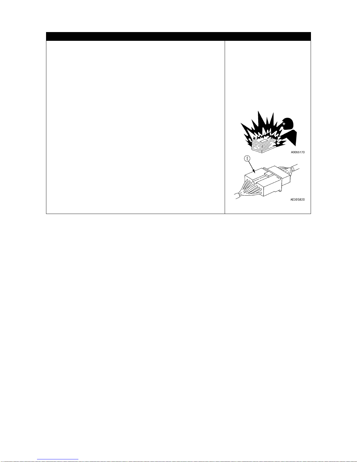
2-11
CAUTIONS UNDER COLD WEATHER
• Remove snow from and defreeze the swing gear, boom and winch
related parts, and check the movements before work.
• Warm up enough.
Attempt to operate the operation levers and switches without
enough warm-up causes the Machine to react dull, and may result in
unexpected accidents.
• Avoid acutely accelerating the engine during short time after
starting the engine.
• Increase the oil temperature of the hydraulic circuit by relieving the
oil pressure (let the pneumatic oil to escape to the hydraulic oil tank
by raising to above the hydraulic circuit set pressure) by using
operation lever. Doing so improves the Machine reactions and
prevents improper operations.
• If the battery fluid is fro zen, do not charge ba ttery or start the engine
using other power source.
Such act may cause the battery to catch fire.
Before charging or starting up using other power source, defreeze
the battery fluid and check that fa ilures such as battery fluid leak do
not exist.
• After end of the work, wipe off and apply wraps if substances such
as condensation, snow or mud are stuck to the wire harness,
connector (1), switches, sensors or similar part.
If the infiltrated condensation and/or similar substance freezes, the
Machine may operate improperly upon the next use and cause
unexpected accidents.
Page 36
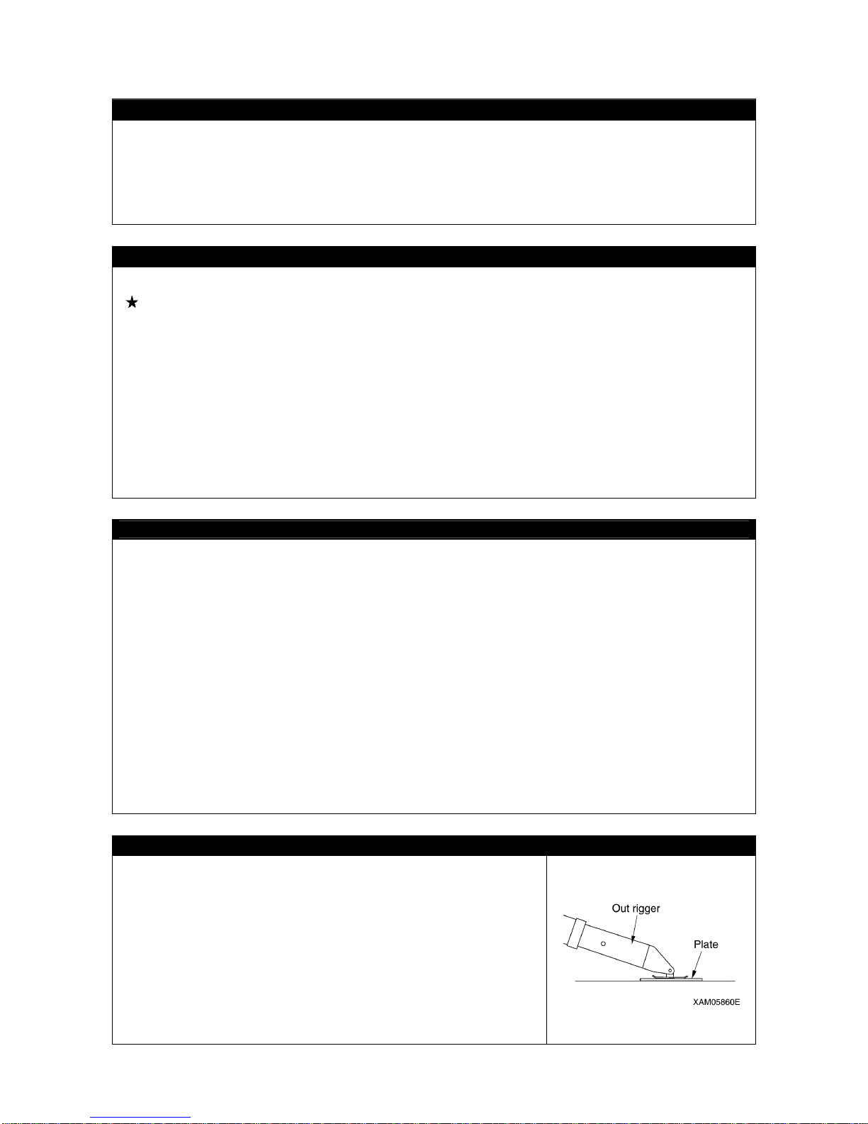
2-12
2.3 WORKING WITH CRANE
INSPECTION BEFORE STARTING WORK
Check that the safety devices and crane operate properly.
• Operate each of the ope ration levers and switches under no loa d, and check that operations take place
without abnormality.
Repair immediately if any abnormality exists.
• Check that the safety devices such as the moment limiter, outrigger safety device, and over hoist
detector / automatic stop device activate properly.
CAUTIONS WHEN HANDLING MOMENT LIMITER
• Use/store the moment limiter under the following ranges of ambient temperature.
Temperature of use: 10 to 50 °C Storage temperature: -20 to 60 °C
• Avoid direct sunlight so that the temperature of the moment limiter body does not exceed the above
range.
• Avoid locations with strong acid or alkaline atmosphere as much as possible. Otherwise, unexpected
failures may occur.
• Do not apply impact to the moment limiter body for instance by colliding with an object.
Such attempt may damage the case and may result in failures and improper operations.
• Do not push the panel sheet of the moment limiter body by a force more than necessary or push with
sharp object such as a tip of a screwdriver. Such act may damage the panel sheet and may result in
failures and improper operations.
• Do not remove the case cover or panel sheet from , or disassemble the moment limiter body. Such a ct
may damage case and/or panel sheet and may result in failures and improper operations.
CAUTIONS WHEN SETTING UP MOMENT LIMITER
• The moment limiter calculates the moments assuming the Machine is level.
If you work with the crane when the Machi ne is not level, warnings and alarms are not issued e ven
when the rated total load is near.
Always set the outrigger horizontally to the ground while looking at the level gauge.
• Before using the crane, check that the boom angle display, boom length display and real load display
of the moment limiter are displayed correctly following the crane movements. Attempt to use without
correct display results in failure to obtain correct measurement result and may result in serious bodily
accidents caused by reasons such as an improper operation and/or breakage of nearby equipment.
• Always make sure the wir e strand setting of the moment li miter matches with the wire stra nd of the
crane. If the wire strands do not match, always let the wire strands match by changing the wire strand
setting of the moment limiter or by changing the wire strand of the crane. Attempt to use with
unmatched wire strands results in failure to obtain correct measurement result and may result in
serious bodily accidents caused by reasons such a s an improper operation an d/or breakag e of nearby
equipment.
• Do not carelessly change the setting when measuring with the moment limiter. Such attempt results in
failure to obtain correct measurement result and may result in serious bodily accidents caused by
reasons such as an improper operation and/or breakage of nearby equipment.
PLACE CRANE ON LEVEL AND HARD SOIL
• Always place the outriggers on a level, stable and solid ground.
Attempt to work with crane without outriggers firmly contacting the
ground may cause the Machine to trip.
• Always place all outriggers before working with crane.
• Do not set any outrigger near the location that may collapse, for
instance a soft ground, roadside or drilled hole.
In case the outriggers need to be placed on a soft ground for
unavoidable reason, always reinforce the ground by laying a
sufficiently large and strong base plate below each of all outrigger
supports.
Page 37
2-13
CHECK OUTRIGGER PLACEMENT CONDITION
Always observe followings to prevent serious injuries and death
accidents when placing the outriggers.
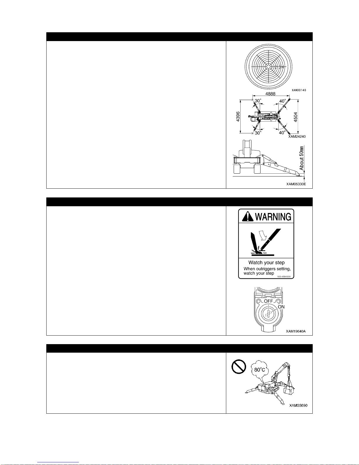
• When placing the outriggers, always keep the Machine sternly level
while looking at the level gauge. Occasionally view the level gauge
and make sure to keep the Machine level during the crane works as
well.
• Place the outriggers at a maximum extension condition as the basic
rule.
In case of placing in a non-maximum extension condition for
unavoidable reason, always find the values outrigger middle
extension or outrigger minimum extension values in the rated total
load chart before work.
• Place the outriggers in a style that the rubber tracks are
approximately 50 mm above the ground.
• Make sure all of the outrigger position pins are securely fixed.
CAUTIONS WHEN PLACING OUTRIGGER
• Do not let people approach nearby when placing the outriggers.
Otherwise, serious accidents for instance the outrigger support
catching a foot may occur.
• Always set the emergency stop cancel switch at side of the
instrument panel to OFF (auto) position before outrigger operation.
Do not attempt any outrigger operation with the emergency stop
cancel switch at ON (cancel) position.
Inspections and maintenance works are the only occasions where
the emergency stop cancel switch is set to ON (cancel) position.
CAUTIONS HIGH TEMPERATURE OIL WHEN WORKING WITH CRANE
When hydraulic oil temperature exceeds 80 degrees, high pressure
hoses and seals can be damaged by heat, and it may cause burn by
spouted oil.
If temperature of hydraulic oil becomes over 80 degrees, stop
operation and wait until the oil cools down.
Continuous hook raising / lowering operation at high working lifting
height and a long time accelerated operation are easier to raise oil
temperature. Especially be careful for these operations.
Page 38
2-14
BEWARE OF ELECTRICAL CABLE ABOVE
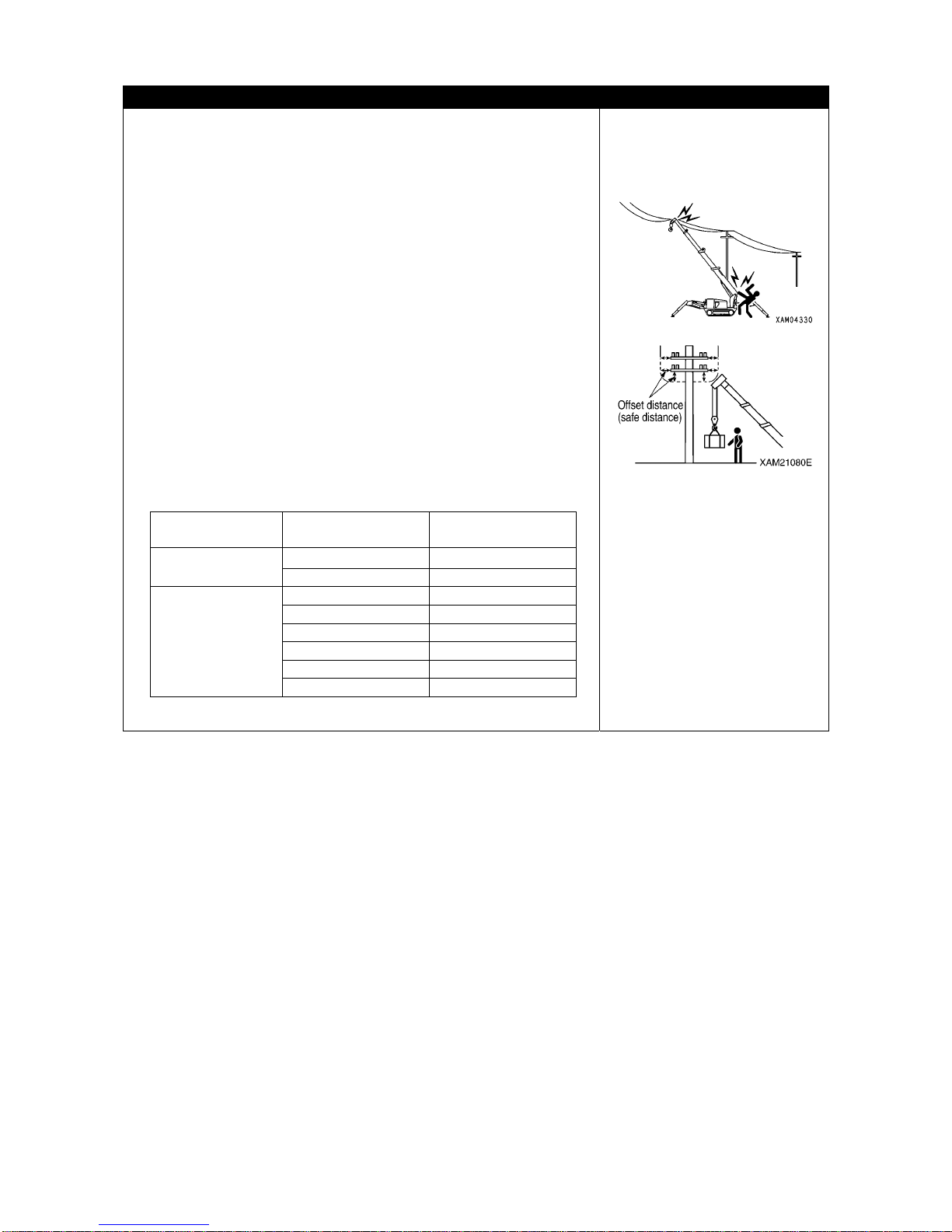
• Do not let the Machine contact with electrical cables above.
High voltage cables may inflict electrical shock by mere
approaching.
• Persons who sling are likely to suffer electrical shocks.
Always observe followings to prevent accidents.
• If the boom or the wire ropes may contact an electrical cable in the
workplace, consult the electricity company and make sure that the
measures (measures for instance placement of a guard personnel
or application of wrap tubes and warning tags to the electrical
cable) stipulated by the related regulations are taken before
starting work.
• Put on rubber soled shoes and rubber gloves, and be careful that
the body parts unprotected by rubber or other insulation do not
contact the wire rope or the Machine frame.
• Place a guide and let him/her wa tch so that the boom, wire ro pe or
Machine frame does not go near the electrical cable too much.
Before doing so, decide the emergency signs and other
necessities.
• Ask the electricity company for the voltage in the electrical cables
in the working site.
• Ensure the offset distances (safe distance) shown in the following
table between the boom/Machine frame and electrical cables.
Voltage of
Electrical Cable
Minimum Safe
Distance
Low voltage
(Distribution line)
100・200V
2m
6,600V 2m
Special
(Transmission
line)
22,000V 3m
66,000V 4m
154,000V 5m
187,000V 6m
275,000V 7m
500,000V 11m
Page 39

2-15
MEASURES WHEN CHARGE ACCIDENT OCCURS
When an electrical charge accident occurred, do not panic but calm down, and apply solution by the
following sequence.
1. Report
Immediately report to the electricity company or related management company, and receive
instructions for the power transmission stop, emergency procedures and related.
2. Evacuation of related personnel from vicinity of Machine
Let the related personnel including the workers from vicinity of the Machine to prevent secondary
disasters.
Personnel who suffered electrical shock by holding a sling rope, guide rope or other conductor when
the Machine was charged should evacuate by his/her own effort.
Do not try to help such person. Otherwise, secondary electrical shock acciden t occurs.
3. Emergency procedure
Take the solution by following sequence in case of urgency where personnel received electrical shock
because the Machine was charged.
(1) If the Machine can be operated, immediately operate the Machine to move the Machine
constructions away fr om the cont act and out of t he range of t he cause of t he charge. B e careful
not to snip the distribution power cable.
(2) Evacuate the Machine completely away from the cause of the charge, make sure the Machine is
not charged, rescue the electrically shocked personnel and immediately carry to the hospital.
4. Measure after accident
After accident, do not reuse as is. Such attempt may cause unexpected accidents and enhances
failures.
Ask us or our sales service agency for repair.
CAUTIONS WHEN WORKING WITH CRANE IN LOCATION WITH HIGH OUTPUT
MICROWAVE EMISSION
Working with crane near a high output microwave emission equipment such as a radar or TV/radio
broadcast antenna causes the crane construction to be exposed to the microwave and generates
induced current, therefore is very dangerous. In addition, the mechatronics may become haywire.
Establish grounding between the Machine frame and the ground when working in such location. In
addition, slingers are requested to wear rubber boots and ru bber gloves since risk of electrical sho ck by
contacting parts such as the hook or wi r e exists.
Page 40
2-16
PAY ATTENTION TO WEATHER INFORMATION
• In case of thunderstorm, risk of lightning exists, so abort working with crane, immediately lower the
load and contain the boom.
• Exposing the hoisted load to wind causes the load to waggle and cau ses the Machine to be unstable,
thus is dangerous. Immediately lower the load and contain the boom when the wind is causing the load
to waggle.
• If the maximum instantaneous wind speed is 10 m/s or greater, abor t working with cran e, immediately
lower the load and contain the boom.
• Even when the maximum instantaneous wind speed is below 10 m/s, bigger the hoisted load, higher
the hoisted load position, and longer the boom, the wind effect increases accordingly. Be fully careful
during work.
• When a load such as a steel plate that has a large area exposed to wind is being hoisted, the wind
arriving from front/rear/side of the boom may cause the Machine to trip or damage the boom. Be fully
careful when working.
• When an earthquake occurs, abort working and wait until the earthquake is over.
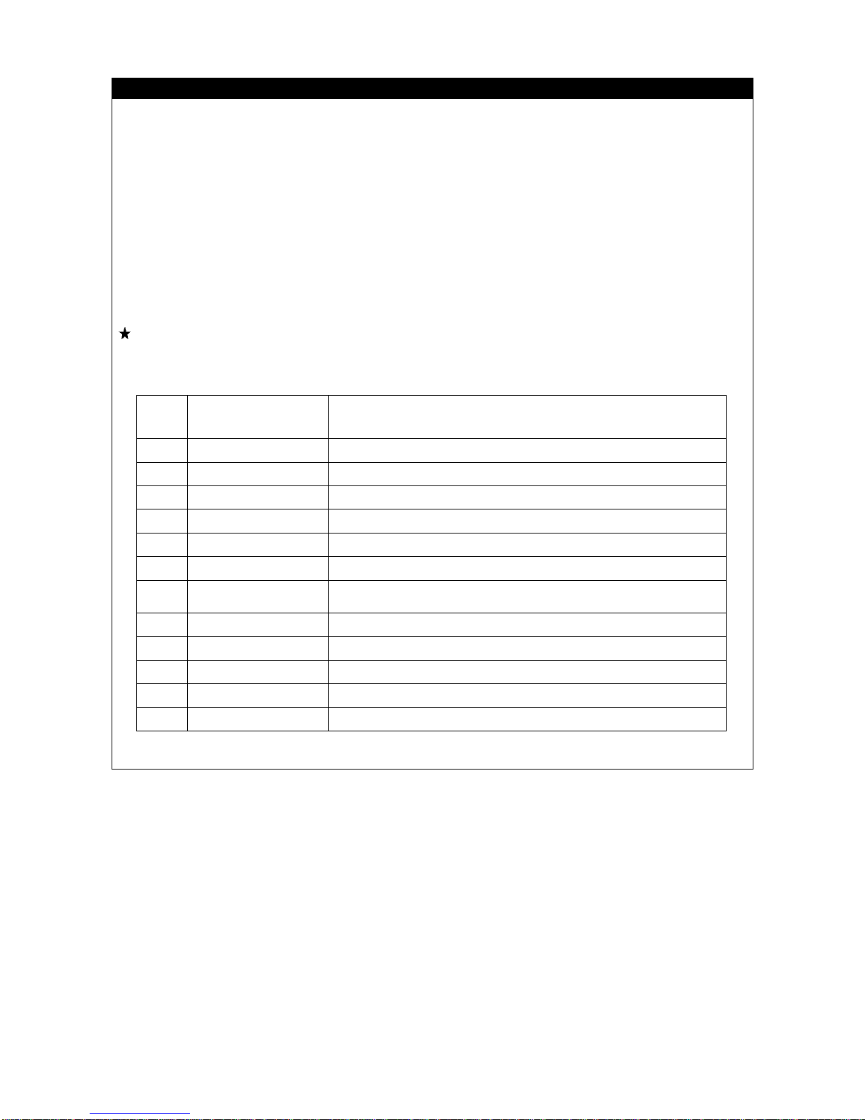
The following table indicates approximate relation between the wind speed and wind effect. The w ind
speed mentioned in the weathercast is mean wind velocity (m/s) during 10 m at 10 m above the
ground.
Force Wind Speed (m/s) Effect On Land
0 Less than 0.3 Smoke rises vertically.
1 0.3 - below 1.6 Wind motion visible in smoke.
2 1.6 - below 3.4 Wind felt on exposed skin.
3 3.4 - below 5.5 Leaves and smaller twigs in constant motion.
4 5.5 - below 8.0 Dust and loose paper raised. Small branches begin to move.
5 8.0 - below 10.8 Smaller trees sway. Some foam and spray.
6 10.8 - below 13.9
Large branches in motion. Whistling heard in overhead wires.
Umbrella use becomes difficult.
7 13.9 - below 17.2 Whole trees in motion. Effort needed to walk against the wind.
8 17.2 - below 20.8 Twigs broken from trees. Progress impeded.
9 20.8 - below 24.5 Light structure damage. Slates blown off.
10 24.5 - below 28.5 Trees uprooted. Considerable structural damage.
11 28.5 - below 32.7 Widespread structural damage.
Page 41
2-17
CAUTIONS WHEN SLINGING
• Check the following before hoisting a load.
Attempt to hoist the load without checking may result in serious bodily accidents by a drop of the load
or tripping.
• Observe the values in the rated total load chart.
• Hoist from the center of gravity of the load.
• Check that the wire ropes of the hook block are perpendicular to the ground.
• When the load leaves the ground, stop winding up the load once and check whether the load is
stable.
• Before hoisting a slung load, always check whether the sling wire rope "retainer device" of the hook
block is hung for sure. If the "retainer device" is not hung, the wire rope may leave the hook blo ck and
cause the load to fall and results in a serious accident.
• Larger wire rope angle when hoisting the load increases force that applies to the wire rope even whe n
the load weight is unchanged, thus may cause the wire rope to snip. Pay enough consideration well
when slinging to prevent excessive for from applying to the wire rope.
• Do not hoist more than loads at once.
Such attempt may cause the hoist bracket to hit and damager the other hoisted load, the loads to move
and loose balance and cause trip, or other cause of serious accidents.
Do not hoist more than one load even if the total is within the rated total load.
• Hoisting of lengthy load causes the load to lose balance and is dangerous.
In case such load, hoist vertically by using a cramp , or achieve b alance of the hoisted load by applying
a rope to both ends of the load.
CAUTIONS WHEN HANDLING WIRE ROPE
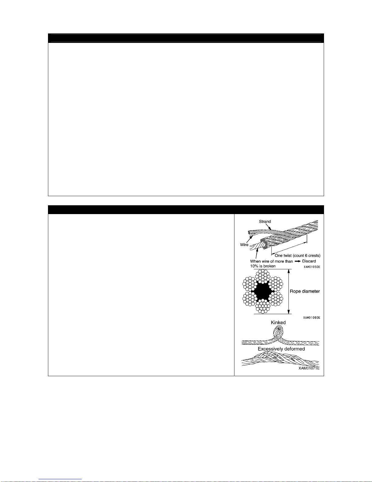
• The wire rope fatigues as the time passes, so inspect every time
before work, and replace immediately if at or beyond the
replacement standard.
At the same time, inspect the sheave at the tip of the boom and the
sheave of the hook block. Damaged sheaves accelerate the
damage of the wire ropes.
• Use the wire ropes specified by us.
• Always put on leather gloves when handling the wire rope.
• Handing worn and damaged wire may cause injure by wire splinter.
• Do not use any wire rope of which any of the followings apply.
• 10% or more of the wires (except the filler wire s) in one twist of the
wire rope are snipped.
• The wire rope diameter abrasion is beyond 7% of the nominal
diameter.
• Is kinked.
• Is excessively deformed or corroded.
• Affected by heat or sparks.
Page 42

2-18
CAUTIONS WHEN WORKING WITH CRANE
• Be sure to verify that the emergency stop cance l switch is at OFF (auto) position before operating the
crane.
Do not attempt the crane operation when the emergency stop ca ncel switch is at ON (cancel) position.
The emergency stop cancel switch is permitted to be at ON (cancel) position only durin g the inspection
or maintenance works.
• Crane works are not possible when the outriggers are placed in extension condition. Also, the crane
work becomes halted when an outrigger support leaves the ground during the crane work. Securely
place the crane in the extension condition, and avoid operations and works that may cause the
machine to vibrate when working with the crane.
• Attempt to work beyond the capacity of the Machine may cause serious accidents and failures cau sed
by for instance tripping or fluctuation. Observe the rated tota l load chart when working with the crane.
• Do not travel with a load being hoisted under any circumstance.
Such attempt may cause the crane to trip a nd may result in serious bodily accidents.
• Be slow when operating the crane.
Sudden lever or accelerator operations may cause risks such as waggling or fall of the load and
collision with the surrounding. Be especially careful to be slow during the swing operations.
• Do not let people approach the work radius or below the load, since risks such as fall of the load and
contact with the load exist. Such attemp t may re sult in seriou s bodily a ccidents. Also, dur in g the work,
consider the fact that the working radius increa ses when the load is hoisted and the boom is deflected
thus.
• Attempt to work with the crane even when the view is bad due to location or weather is dangerous.
Ensure brightness by posting a work lamp or other illumination facility in dark places.
When the view is bad because of bad weather (rain, fog, snow), abort working and wait until the
weather recovers.
• Do not use for purpose, for instance raising a person using a crane, other than the true purpose.
• If the overwinding detector alarm buzzer is heard, immediately leave your hand from the winch lever.
The hook block winding stops. Then, operate the w inch lever to Down (push forward) to wind down the
hook block. In addition, the hook block is wound up when the boom is extended, so be sure to ensure
extra clearance between the boom and the hook block during work.
• When the boom extends, the hook block is wound up.
Operate the winch lever to Down (push forward) to wind down the hook block while you extend the
boom.
• Whenever an overload occurs during work, lower the load by winding down the winch by setting the
winch lever to Down (push forward).
Do not raise or lower the boom acutely. Such attempt may cause serious accidents by tripping.
• The volume of the hydraulic oil in each of the cylinders changes depending on the temperature.
By leaving idle with a load being hoisted, as the time passes by the oi l temperature drops and the
hydraulic oil volume decreases, and changes such as the boom derrick angle decrease and boom
length decrease may occur.
In that case, execute boom derricking operations and boom extension operations appropriately to
correct.
• Do not leave the driving operation position when a load is hoisted.
Lower the load before leaving the Machine.
• Keep the hook block wound up when not in use.
Otherwise, person near the load may collide the hook block without load.
• The operator must always ensure that no one is ever underneath a hoisted load.
To ensure safety, any lifting carried out over the driver's seat must be operated by remote control.
Page 43
2-19
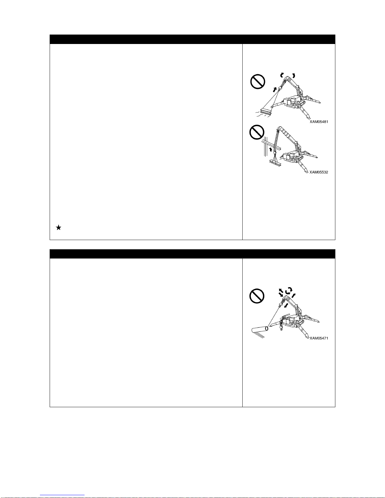
CAUTIONS WHEN OPERATING WINCH
• Do not let persons enter below the hoisted load.
• When hoisting a load, always stop once at the "takeoff" position
where the hoisted load leaves the ground. Check subjects such as
load stability and load force, then hoist up the load.
• Do not pull laterally, pull toward you or hoist diagonally. Such
attempt may cause the crane to trip or suffer damage.
• Overwinding of the hook block may re sult in collision with the bo om,
snipping the wire ropes and causes the hook block and load to fall
and cause serious accidents. Be fully careful to prevent overwinding
the hook block.
• Be careful to prevent the wire rope and/or hoisted load from
contacting an obstacle such as a tree or steel when hoisting a load.
If caught by an obstacle, do not forcibly wind up the hoist load, but
untangle the caught part before winding up.
• Do not use the winch drum wire rope in random condition. If
random, not only the wire rope suffers damage and shortens the
lifetime, but the wire rope may snip and causes serious accidents.
Observe following precautions to avoid wire rope from becoming
random.
• Do not let the hook block hit the ground.
• Before leaving the hook block lowered for a long time for instance
when working with underground, leave at least three loops of wire
rope in the winch drum.
• If the wire rope is twisted and causes the hook block to turn, fully
eliminate the twist before work.
See “ Operation 4.2 What to do with Twisted Wi nch Wire Rope”
for details.
CAUTIONS WHEN OPERATING BOOM
• Be slow as much as possible when operating the boom operation
lever.
Especially avoid sudden lever operations when the load is hoisted,
which may cause the load to waggle and give large impact to the
Machine, and thus may damage the crane or trip th e Machine.
• When the boom is lowered, the working radius increases, and the
rated total load that can be hoisted decreases. When working while
raising/lowering the boom, pay extra attention so that the mass
(weight) of the load at the time the boom is most lowered does not
cause overloading.
• Attempts to pull the load laterally or pull to bring forth the load by
raising/lowering and/or extracting/retracting operation of the boom
are prohibited. Do not attempt under any circumstance.
• Be aware of the hook block windup condition and exercise caution
when extending or retracting the boom.
• When the boom is extended, the working radius inc r eases, and the
rated total load that can be hoisted decreases. When working with
extending/retracting the boom, pay extra attention so that the mass
(weight) of the load at the time the boom is most lowered does not
cause overloading.
Page 44
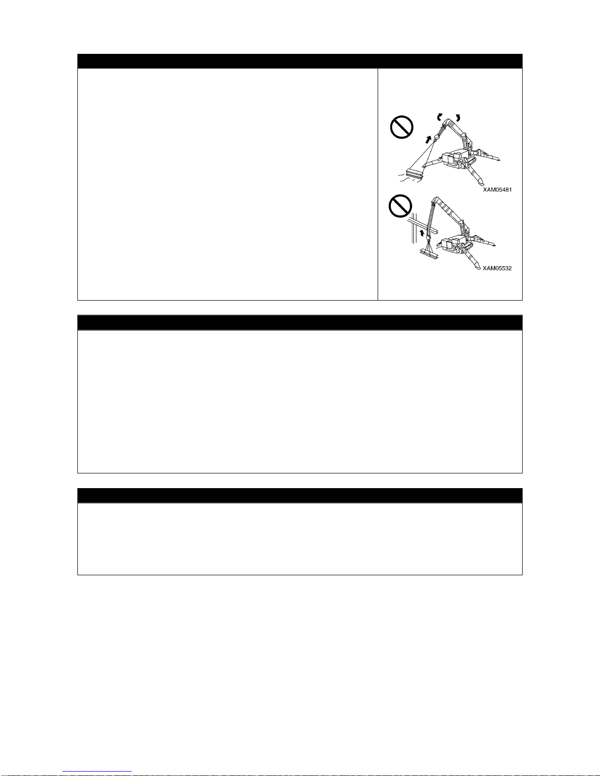
2-20
CAUTIONS DURING SWING OPERATION
• Check the safety in the vicinity and blow the horn before swinging.
• If the boom derrick angle is small, be careful to prevent the boom
from hitting the driver or the Machine.
• Be slow as much as possible when operating the swing lever . Make
sure to start smoothly, swing slow, and stop quietly.
Especially avoid sudden lever operations when the load is hoisted,
which may cause the load to waggle and cause the Machine to lose
balance, and thus may damage the crane or trip the Machine.
• Attempts to pull to bring forth the load or let the load stand up by
swinging operation are prohibited. Do not attempt under any
circumstance.
• Be careful to prevent the wire rope and/or hoisted load from
contacting an obstacle such as a tree or steel when hoisting a load
or when swinging.
If caught by an obstacle, do not forcibly wind up the hoist load, but
untangle the caught part before winding up.
• Certain outrigger extension condition may cause the boom to hit an
outrigger and cause the crane to be da maged or the Mach ine to trip.
Be careful to prevent the boom from hitting outriggers during swing
operation.
COOPERATION HOISTING IS PROHIBITED AS THE RULE
Cooperation hoisting, that is to use more than one crane to hoist a load, is prohibited.
The cooperation hoisting work is a highly hazardous work that may cause for instance a trip of the
Machine due to uneven center of gravity, fall of the hoisted load or boom damage.
If the need to work so exists for unavoidable reason, establish a work scheme by responsibility of the
user, discuss fully, let the worker fully acknowledge the work method and procedures, then work
carefully under the direct leadership of the work supervisor.
And, observe the following cautions as well.
• Use the cranes of same model.
• Choose the Machine model that can handle sufficiently larger load than the load to be hoisted.
• Make sure only one person gives signs.
• Limit the crane operations to single operations as the rule, and do not attempt any swing operation.
• Appoint one responsible slinger who is most experienced.
WORKING AT THE SITE WITH UNDERGROUND LIFTING
• Leave at least three loops of wire rope in the winch drum when winding down the wire rope in ca se of
underground work or similar occasion. This Machine is equipped with three-winding stop alarm /
automatic stop device as the safety device, but even then be fully care fu l to prevent th i s safe ty devi ce
from activating.
• Make sure signs are communica ted fully.
• Be especially careful with the crane operations.
Page 45
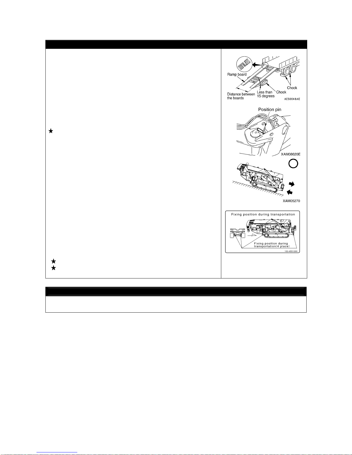
2-21
3. TRANSPORT PRECAUTIONS
CAUTIONS WHEN LOADING OR UNLOADING
• Be especially careful when loading or unloading the Machine
because the risks intervene.
• Select a location that is level and has firm road surface when
loading or unloading the Machine. In addition, keep enough
distance from the roadside.
• Use the ramps under 15 degrees or smaller angle. In addition,
decide the clearance between ramps to meet the center of the
rubber tracks.
• Always set the Machine in the "traveling posture" and securely
insert the position pins (4 pieces) to the outrigger ro tary parts before
loading or unloading the Machine.
See “Operation 2.5 Machine Travel Posture” for details.
• Always move backward when loading the Machine. Moving for ward
may cause a trip.
• When loading or unloading, set the engine rotation to low idling (low
speed rotation) and operate slowly by low speed travels.
• Use th e ramps that have fully strong w idth, length and thickness,
and that enable safe loading/unloading.
Reinforce with blocks or other substances if the ramps deflect
much.
• Remove the mud and other substances from the footing to prevent
the Machine from skidding over the ramps. Remove the substances
stuck the ramps such as grease, oil or ice, and keep clean.
Be especially careful in the rainy days where slips easily occur.
• Do not change direction over a ramp. Temporarily leave the ramp
before correcting the direction.
• Be slow when operating to change the direction on the truck
platform where the footing is unstable.
• After loading the Machine, apply the wood blocks so that the
Machine does not move, and securely fix with wire ropes or other
means.
See “Operation 5.1 Loading/unloading” for details.
See “Operation 5.3 Cautions in Loading Machine” for details.
CAUTIONS DURING TRANSPORT
Observe the related regulations and exercise safety during transport.
Page 46
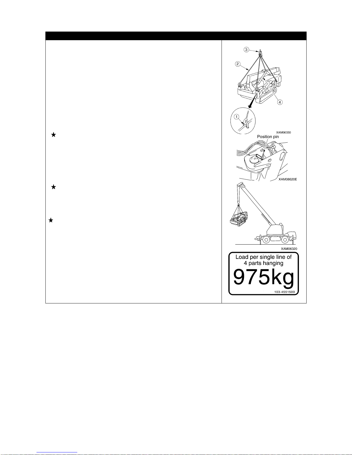
2-22
CAUTIONS WHEN LOADING/UNLOADING WITH CRANE
Be careful of the followings when loading or unloading the Machine
by hoisting with a crane.
• Do Not use those brackets on the boom to hang the whole unit.
• Before hoisting the Machine, attach the hoisting brackets (1) (for
instance shackles) to the outrigger rotary holes (four), and hang the
wire ropes (2) (four) on the hook (3).
• To hoist, use the crane, wire ropes (2) and hoisting bracket (1) (for
instance shackles) having enough strength against the Machine
mass (weight).
Following is the load force that applies to each of the wire ropes
when the Machine main body is hoisted by four wire ropes.
Standard sp ecification: 975 kg
• ALWAYS set the Machine in the "traveling posture" and securely
insert the position pins (4 pieces) to th e outrigger rot ary p art s before
hoisting the Machine.
The center of gravity position of the Machine has been decided
under the condition where the Machine posture was "traveling
posture".
See “Operation 2.5 Machine Travel Posture” for details.
• Use the carrying instruments shown the right figur e and work safely
when carrying the Machine using a crane.
Recommended hoisting equipment
• Wire ropes (two in front): 12.5 diameter x length of 2150 mm
(breaking force of 7.5 t or more), with eye lock and nominal 12A
thimble at one end
• Wire ropes (two in back): 12.5 diameter x length of 1650 mm
(breaking force of 7.5 t or more), with eye lock and nominal 12A
thimble at one end
• Shackle: BC or SC, nominal 14
Page 47
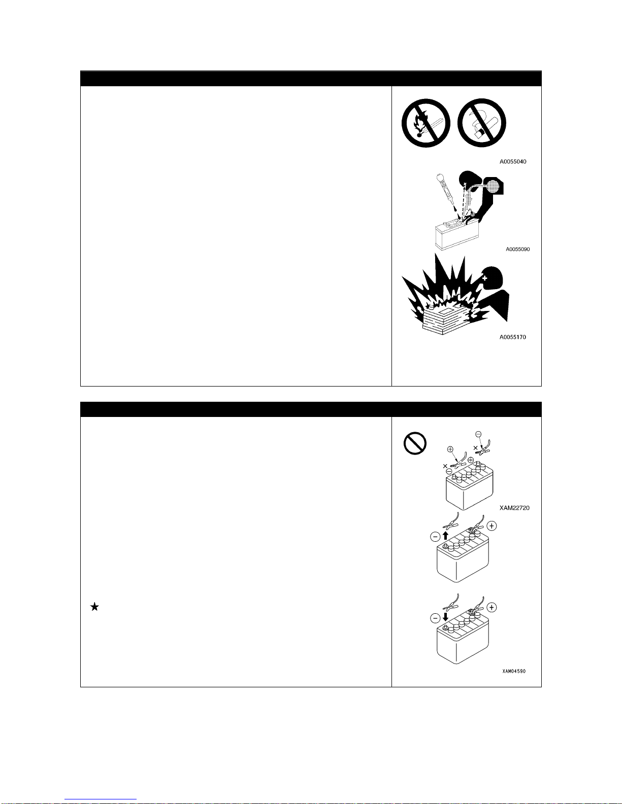
2-23
4. BATTERY HANDLING PRECAUTIONS
BATTERY HANDLING CAUTIONS
The battery fluid includes diluted sulfuric acid, and generates
hydrogen gas, and causes bodily accidents and fires if handle
improperly, so always observe the followings.
• Do not let a cigarette or any fire source approach the battery.
• Always put on protective glasses and rubber gloves before han dling
the battery.
• If the battery fluid contacted clothing or skin, immediately wash
away by huge quantity of water.
• If the battery fluid entered an eye, wash immediately wi th water and
see the doctor as soon as possible.
• If you have swallowed the ba ttery fluid by mishap, immediately drin k
huge quantity of water, milk, raw egg or vegetable oil, and see the
doctor as soon as possible.
• Wipe with a wet clean cloth when cleaning the battery upper surface
or related part. Do not use organic solvent or detergent for instance
gasoline or paint thinner.
• Tighten the battery cap fully.
• If the battery fluid is fro zen, do not charge ba ttery or start the engine
using other power source. Such act may cause the battery to catch
fire.
• Before charging or starting up using other power source, defreeze
the battery fluid and check that fa ilures such as battery fluid leak do
not exist.
• Always detach the battery from the Machine frame before charging
the battery.
CAUTIONS WHEN STARTING UP USING BOOSTER CABLE
Wrong booster cable connection method may result in fire , so always
observe the followings.
• Start the engine by two persons, with one standing on the driving
operation position in the travel operation panel side.
• When starting using other Machine, be careful to prevent contact
between the normal Machine and broken Machine.
• Keep the starter switch key of both the normal Machine and the
broken Machine in OFF position when the booster cable is
connected.
• Do not connect to wrong side [connecting (+) to (-), (-) to (+)] when
connecting the booster cable.
• Start connecting from (+) terminal first, but start disconne cting from
(-) terminal (ground) first.
• Connect the ground to the (-) terminal of the battery of the broken
Machine when connecting the ground as the last procedure.
See “Operation 8.4 Starting Engine with Booster Cable” for
details.
• Avoid the contact between clips of the booster cable, and contact
between a clip and the Machine when disconnecting the booster
cable.
Page 48
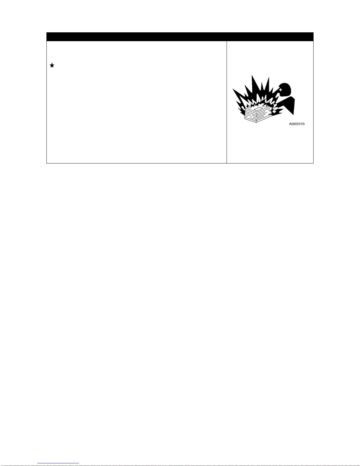
2-24
CAUTIONS WHEN CHARGING BATTERY
Improper handling when charging the battery may cause the battery
to explode. Follow the manuals attached to the Machine and the
charger, and always observe the followings.
See “Operation 8.3 Cautions in Charging Battery” for details.
• Carry the charger to a location with good ventilation, then remove
the battery cap. Doing so causes the hydrogen gas to disperse and
prevents explosion.
• Adjust the charger voltage to suit the voltage of the battery to
charge. Mistake in adjusting the voltage may cause explosions due
to overheat and ignition of the charger.
• Sec urely fix the (+) charge clip of the charger to the (+) terminal of
the battery, then securely fix the (-) charge clip to (-) terminal of the
battery.
• Set the charge current to no more than 1 /10 of th e rated capa city of
the battery, or, in case of quick charge, set to the rated capacity of
the battery or smaller.
• Excessive charge current may cause leap fire and explosion
caused by fluid leak or fluid deficiency.
Page 49
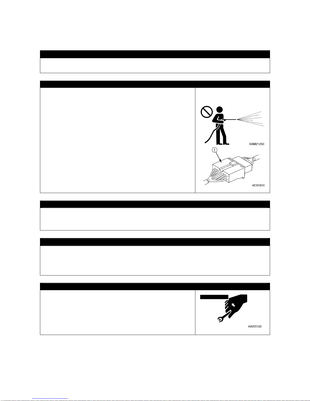
2-25
5. MAINTENANCE PRECAUTIONS
5.1 PRECAUTIONS BEFORE MAINTENANCE
FAILURE REPORT
Execution of a maintenance not described in our manual may cause unexpected failures.
Ask us or our sales service agency for repair.
CLEAN BEFORE INSPECTION OR MAINTAIN
• Before starting an inspection or maintenance, clean the Machine
and prevent rubbish from entering the Machine and make sure the
safety will be ensured during maintenance.
• Attempt to inspect or maintain with the maintenance Machine still
dirty not only lessens chance of locating faulty part, but may cause
rubbish or mud entering your eye, or slipping and tripping that
results in injury.
• Always observe followings when washing the vehicle.
• Use antislip shoes to prevent slips and trips caused by wet
foothold.
• Put on protective equ ipment when using a high pressure steam car
wash. Avoid the accidents that the contact with high pressure
water causes the sk in lacer ation or m ud or ot her subst ance flyi ng
into eye.
• Do not directly spray water onto electrical system (sensors,
connector (1), receiving box and related). Entrance of water into
the electrical system causes faulty operations and may trigger
improper operations, thus is dangerous.
TIDY UP WORKPLACE
In the workplace, put away the tools, hammers and other thing s that obstruct the works, wi pe of slippery
items such as greases and oils, and exercise tidy up and cleaning for safe work.
Untidy workplace may cause stumbles and slips that result in injury caused by tipping.
FOLLOW SUPERVISOR INSTRUCTION DURING TEAMWORK
Appoint a person who supervises the work and follow his/her instructions in case of Machine repair or
installing/uninstalling a work device.
Unexpected accidents due to misunderstood communication between workers may occur during
teamwork.
USE APPROPRIATE TOOLS
Do not use damaged or deteriorated tool, or use a tool for a purpose
that is not a proper purpose of use. Use tools suitable for the
maintenance work.
Entrance of a broken piece of a tool such as a boss with crashed
head or a hammer may destroy eyesight.
Page 50
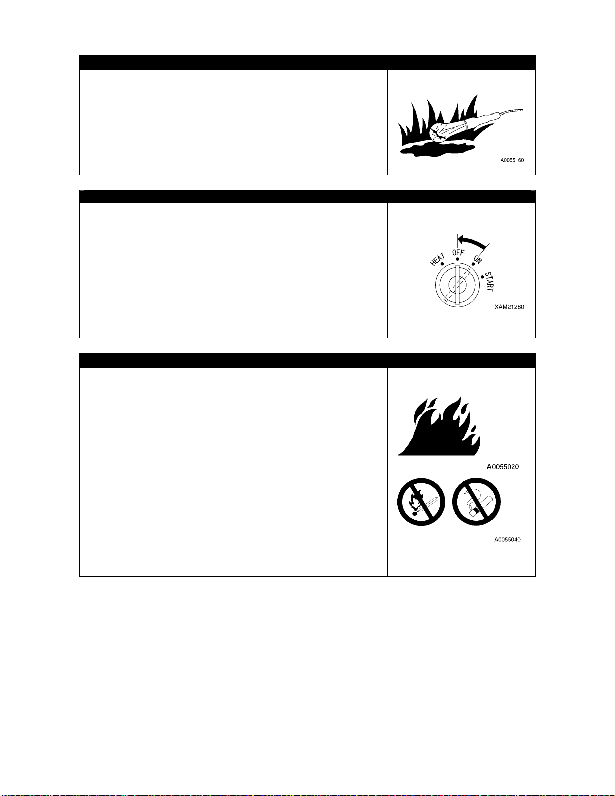
2-26
HANDLING ILLUMINATION DEVICES
• Use explosion proof illumination device when inspecting with fuel,
oil, battery fluid or similar substance. Failure to use explosion proof
illumination device may cause leap fire and explosion.
• Attempt to work without using illumination device in a dark place
may cause injury or other issue. Always use illumination device.
Do not use a lighter or other burning object even if dark. Such use
may cause fire, and furt herm ore t he ba tte ry gas ma y ca tch f ire an d
explode.
STOP ENGINE BEFORE INSPECTION OR MAINTENANCE
• Before inspection or maintenance, always park the Machine at a
location where the ground is level, rock-falls and landslides do not
occur, is a lowland and flood does not occur, and fully retract and
lower the boom, and stop the engine.
• Operate each of the crane operation levers forward backward
several times to relief the pressure remaining in the hydraulic
circuits.
• Apply pawls to so that the prevent rubber tracks do not move.
• Persons in charge of the maintenance should pay attention to
prevent physical body and clothes from contacting the moving parts.
FIRE RISK PREVENTION
Always observe the followings during maintenance where the fuel,
oil, battery or other substance that may catch fire is handled.
• Keep the fuel, oil and any o ther easily combustible oil and fats a way
from fire during storage.
• Do not leave the site when replenishing the fuel or oil.
• Use incombustible cleaning oil for the objects such as the
components, and do not use light petroleum, gasoline or anything
else that may catch fire.
• Do not smoke when inspecting or maintaining. Smoke at a location
designated to do so.
• When inspecting fuel, oil, battery fluid or similar , use explosion proof
illumination devices but do not use fires su ch as a lighter or a match
for illumination.
• Loosened and damaged electrical connections may cause short
circuit that may result in a fire. Inspect accordingly during the
inspections before starting work.
• Make sure a fire extinguisher is place near the inspection /
maintenance site.
Page 51
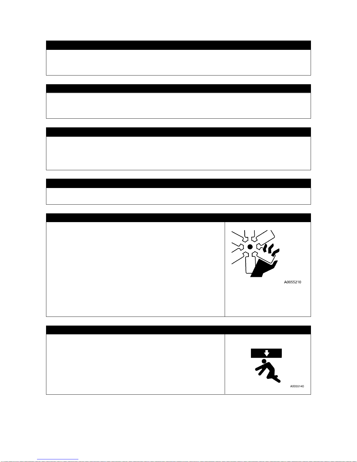
2-27
5.2 PRECAUTIONS DURING MAINTENANCE
NO UNAUTHORIZED PEOPLE
Do not admit anyone other than necessary workers during maintenance. And post a guard as
necessary.
Be especially careful in case of a polishing, welding work, or digging work.
MEASURES UPON FINDING ABNORMALITY DURING INSPECTION
• Always repair whenever an abnormality is found during inspection.
Attempt to use without repairing the defect may cause bodily accidents.
• Ask us or our sales service agency for repair depending on the failure type.
DO NOT DROP TOOL OR PART INSIDE MACHINE
• Do not drop any bolt, nut or tool insid e the Machine when in specting while o pening the in spection port
or tank replenishment port. Dropped object may da mage the Machine or cause the Machine to operate
improperly and thus may cause accidents. If dropped, always retrieve.
• Do not keep anything unnecessary for the inspection in your pocket.
NOISE CAUTION
Large noise in the surroundings may cause hearing difficulty or deafness.
Put on ear covers or earplugs before long time noise exposure for instance an engine maintenance.
WORK BY AT LEAST TWO PERSONS DURING MAINTENANCE WITH ENGINE RUNNING
To prevent accidents, do not attempt maintenance when the engine
is running.
Always observe the followings in ca se of main tainin g with the engine
running for unavoidable reason.
• On e shoul d seat i n the drivi ng s eat, and keep ch eckin g each ot her
while ensuring that the engine can be stopped any time.
• Be es peciall y careful whe n working ne ar a rotat ing part whic h may
entangle.
• Do not touch operation levers. Before handling an operation lever
for unavoidable need, always give a sign to other person and let
him/her evacuate to a safe place.
• Do not contact with the alternator drive belt or other part that severs
upon contact with human body or tool.
CAUTIONS WHEN WORKING BELOW MACHINE
• Park the car over a level and firm location, and fully retract and
lower the boom.
• Before the maintenance below the Machine, extend the outriggers
maximum so the Machine lifts. When doing so, insert support
platforms (height increasers) below front and rear o f the Ma chin e to
stabilize the Machine.
Page 52
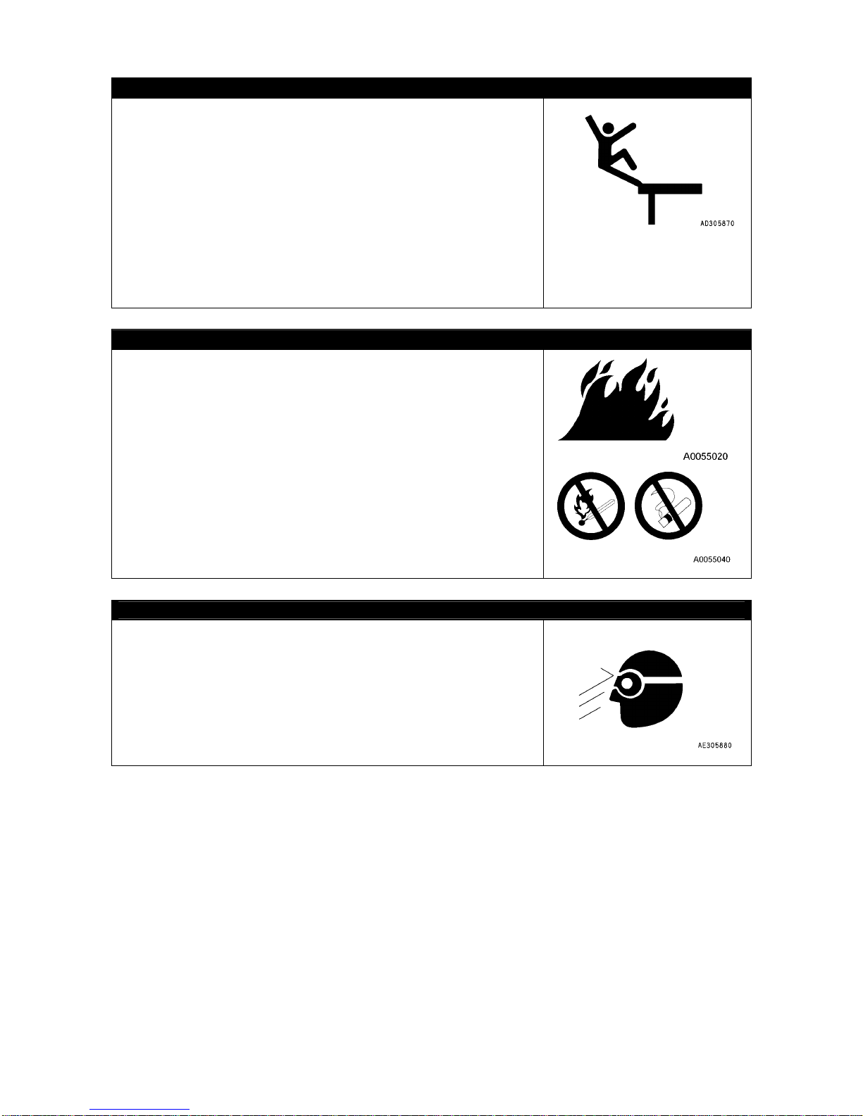
2-28
CAUTIONS WHEN WORKING ABOVE MACHINE
• Tidy the footing to avoid falling and always observe following
precautions during maintenance above the Machine.
• Do not spill oil or grease.
• Do not sprawl the tools.
• Beware of the footing when walking.
• Do not jump from the Machine under any circumstance.
Use a platform, and secure your body with three locations of the
limbs (both feet and one hand, or both hands and one foot) when
climbing up or down the Machine.
• Use protective equipment that suit the work.
• Do not step on the boom, outrigger or machinery cover to prevent
bodily accidents such as falling or tripping due to slippage.
CAUTIONS WHEN REPLENISHING FUEL OR OIL
The fuel, oils and similar substance may catch fire if a fire comes
near.
Light petroleum is used as the fuel and thus requires extra effort to
observe the followings.
• Keep the engine stopped when supplying.
• Do not smoke when supplying.
• Immediately wipe away dripped fuel or oil.
• Securely tighten the fuel and oil caps.
• Supply fuel/oil at a location with good ventilation.
• Do not leave the site when replenishing the fuel or oil.
BEWARE OF CHIPS WHEN WORKING WITH HAMMER
During the hammering works, keep protective equipment such as
protective glasses and a helmet on, and inse rt a copper bar or similar
object between the hammer and the target when hitting.
Giving impact to a hard metal part such as a pin or a bearing may
cause the broken chip to enter eye and inflict injury.
Page 53
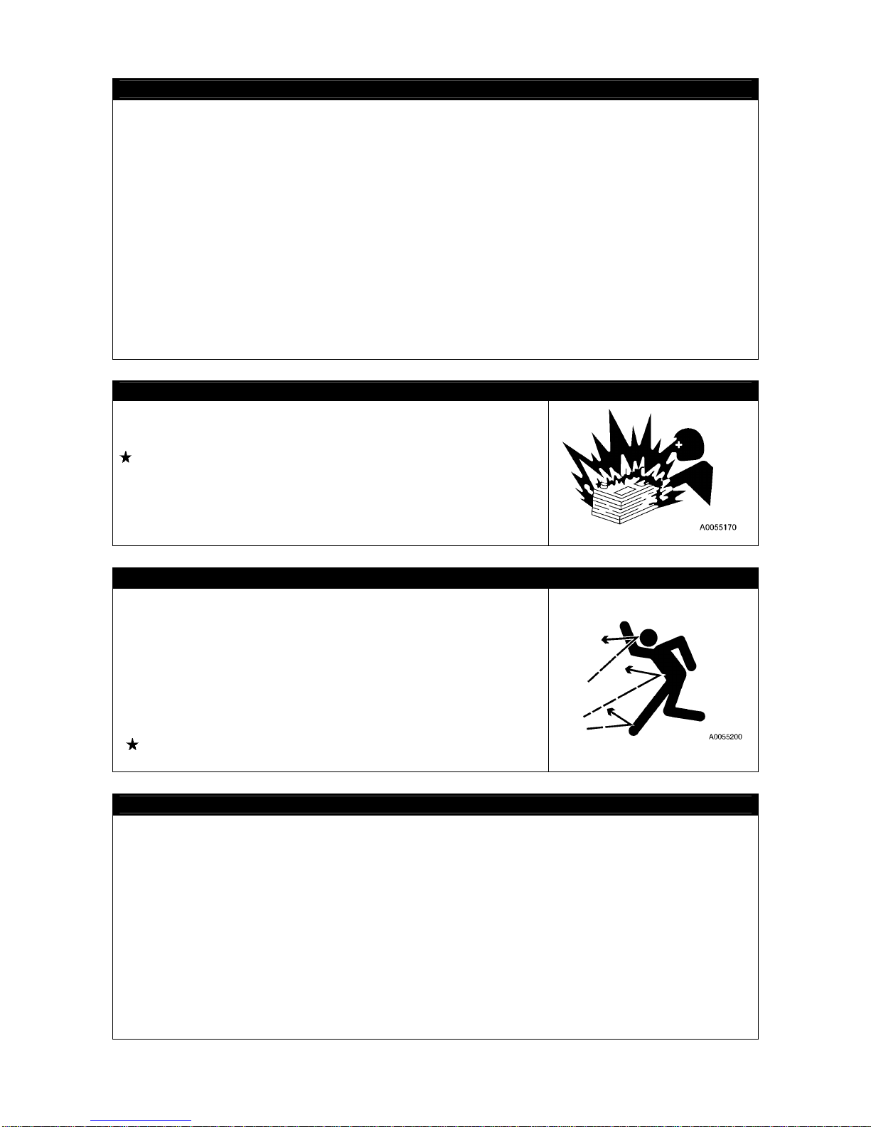
2-29
CAUTIONS DURING WELDING REPAIR
Weld in a location with good facility, and, only authorized personnel are permitted to weld.
Unauthorized personnel are strictly prohibited since risks such as gas generation, fire and electrical
shock are present when welding.
The personnel authorized to weld are requested to always observe the followings.
• Disconnect the battery terminals to prevent battery explosions.
• Peel off the paint from the welding section to prevent gas generation.
• Attempt to heat up a hydraulic machinery, piping or a section near such part may cause combustible
vapor or mist to be generated and catch fire. Avoid heating such section.
• Directly heating a pressurized piping or rubber hose may cause a sudden snip. Apply a fire pro tection
cover.
• Disconnect the wiring connectors of the radio control and remote control devices, moment limiter
display and converter.
• Put on protective equipment.
• Keep the ventilation well.
• Put away the combustibles and prepare a fire extinguisher.
• Do not ground to a location near electrical part. Such may cause the electrical part to malfunction .
DISCONNECT BATTERY TERMINAL
Disconnect (-) terminal of the battery and stop the electrical flow
before repairing th e electrical system or starting an electrical weld.
See “Operation 8. Battery Handling” for details.
CAUTIONS WHEN ADJUSTING RUBBER TRACK TENSION
• Grease is sealed inside the rubber track tension adjuster. The grea
se is at a high pressure because of the tension of the rubber track.
Attempt to release the grease withou t o bserv ing the followin g pre ca
utions may cause the grease valve to pop out and result in serious
accident.
• Do not loosen the tension adjustment grease valve one full turn or
above. Doing so may cause the grease valve may pop out.
• To avoid the risk during tension adjustment, do not place your body
in right front of the grease valve.
See “Operation 2.1.3 [1] Checking/adjusting Rubber Track
Tension” for details.
HIGH PRESSURE HOSE HANDLING CAUTIONS
Oil leaking from high pressure hose may cause fire or bodily accident due to faulty operation.
Whenever a damaged hose or loosened bolt is found, abort working and ask us or our sales service
agency for a repair.
• Replacement of high pressure hose requires experienced skill. In addition, the tightening torques are
decided by the horse types and size.
Customers are prohibited to repair.
• Replace the applicable part if any of the following conditions is found.
• Hose sleeve damage or leak.
• Scratch or truncation of the coat, or exposure of reinforcing layer of a wire
• Coat is partially swollen.
• Indication of twist or collapse is at a movable part of hose.
• Alien object buried in coating.
• Hose sleeve deformation.
Page 54
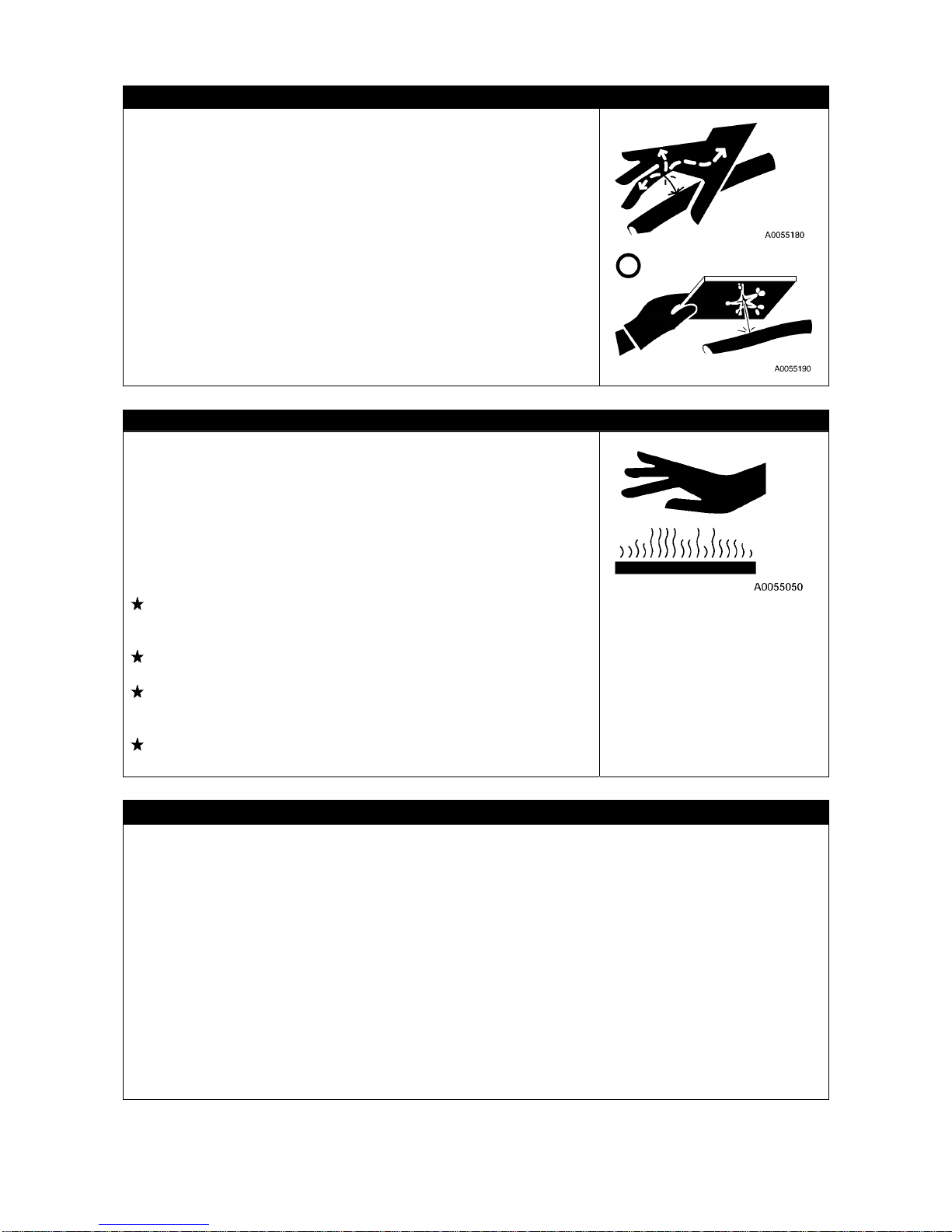
2-30
HIGH PRESSURE OIL CAUTIONS
Failure to make sure the pneuma tic circuit pressure is relieved be fore
inspection or replacement of a high pressure piping or hose may
result in bodily accidents.
Always observe the followings.
• Do not start any inspection or replacement before the pressure
dissipates.
• Put on protective glasses and leather gloves.
• When a piping or hose leak exists, the piping/horse itself or vicinity
or the ground is wet. If such is seen, a piping crack, hose crack or
inflation is considerable, so always ask us or our sales service
agency for a repair.
• High pressure oil leaking through a small hole may puncture the
skin or destroy eyesight upon contacting with skin or eye.
If the high pressure oil gave serious inj ury to skin or eye, wash a way
with flowing water and see the doctor as soon as possible.
CAUTIONS WHEN TEMPERATURE IS HIGH
Parts such as the engine, all oils, exhaust system manifold and
muffler are at high temperature during short time after stopping the
engine.
Attempt to remove the cap or execute a maintenance such as oil
draining, water draining or filter replacement may result in suffering
burns.
Wait until the temperature lowers, then execute the
inspection/maintenance following the procedure written in this
manual.
Operation 2.1.2 Checking Before engine starting: checking cooling
water level, checking oil level in engine oil pan, checkin g oil level in
hydraulic oil tank.
Maintenance 8.8 250 hours maintenance: Replacement engine
lubrication oil and filter cartridge,
Maintenance 8.9 500 hours maintenance: Replacement engine
lubrication oil and filter cartridge, replacement hydraulic oil return
filter
Maintenance 8.10 1000 hours maintenance: Cleaning inside
cooling system, replacement oil inside hydraulic oil tank
CHECKS AFTER INSPECTION/MAINTENANCE
Failure to execute an inspection/maintenance item or failure to check the function and operation of the
maintained part may cause an unexpected fault which may result in bodily accidents.
Always observe the followings.
• Checks with engine stopped
• Check for unexecuted inspection/maintenance.
• Check that inspection/maintenance was done without errors.
• Check for any dropped tool or part. Ones caught by the interior or lever related link me chanism poses
extra danger.
• Check for any fuel leak, water leak, oil le ak, b olt loose and similar issues.
• Check with engine running
Be fully careful with safety when checking with the engine running while referring to "Work by at least
two persons during maintenance with engine running" section.
• Check that the inspected/maintained part operates normally.
• Check that issues such as an oil leak do not occur when load is applied to the oil pressure by
increasing the engine rotation.
Page 55
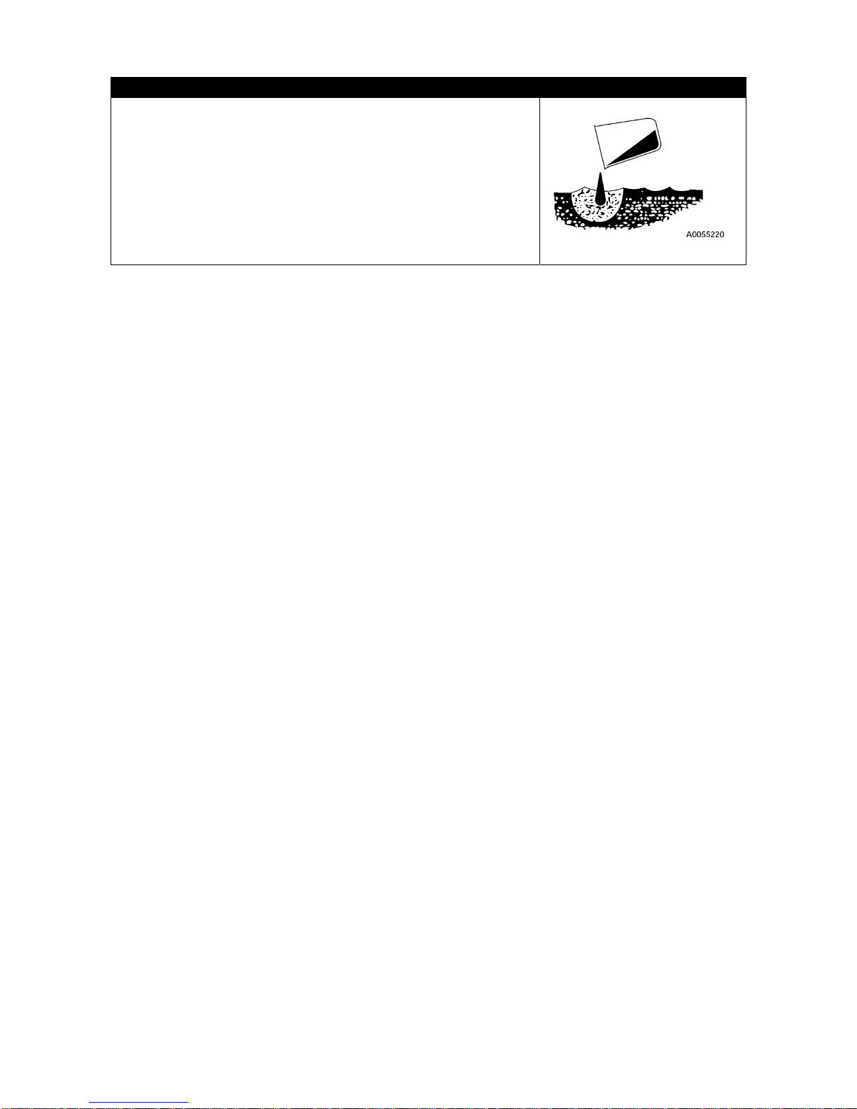
2-31
CAUTIONS WHEN TREATING WASTE
Always observe the following to prevent pollution environment of the
district inhabited with human or animal.
• Do not dispose the waste oil down a water system such as sewage
or river.
• Always drain into a container when draining the oil from the
Machine.
Do not directly drain to the ground.
• Observe the applicable legal regulations and rules when disposing
harmful substance such as the oil, fuel, solvent, filter or battery.
Page 56
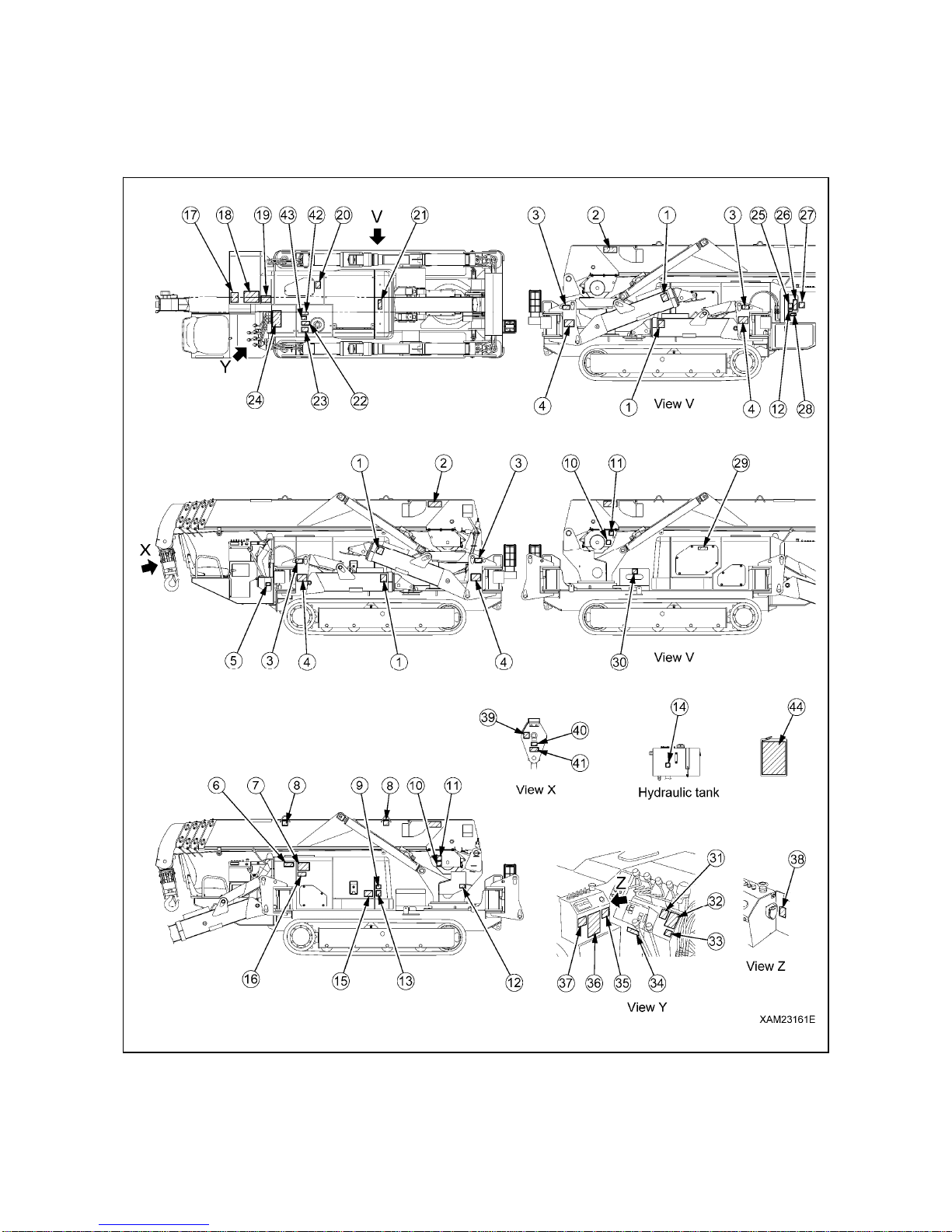
2-32
6. SAFETY LABEL LOCATIONS
Keep these labels clean all the time.
If lost, apply again or replace with new one.
Labels other than the following safety labels exist, treat same.
Page 57
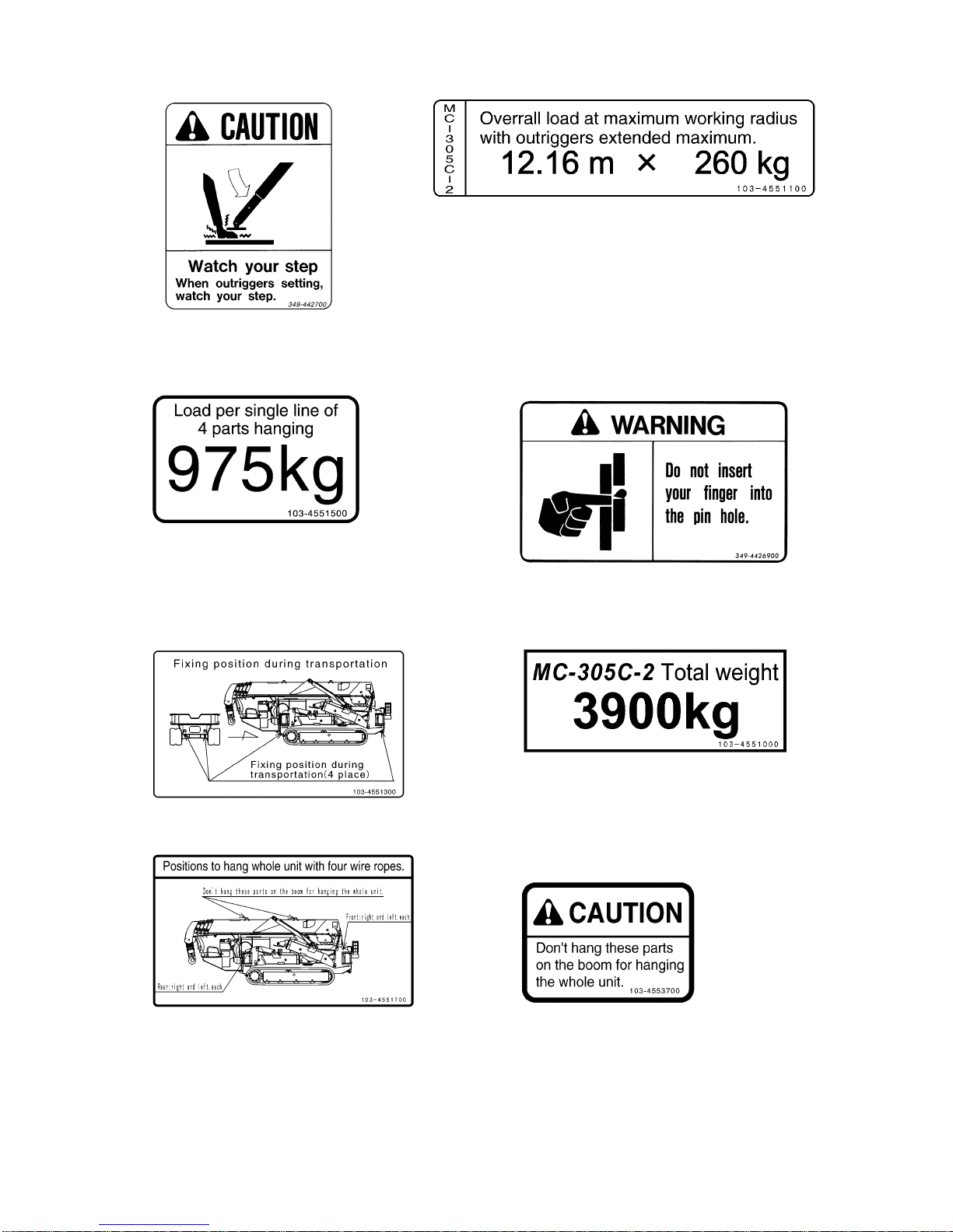
2-33
(1) Footing check (349-4427000) (4 places) (2) Minimum hoist load (103-4551100) (2 places)
(3) Loads on 4-rope machine hoisting (4) Outrigger pin hole caution (349-4426900)
(103-4551500) (4 places)
(5) Fixing bracket position during transportation (6) Machine total weight (103-4551000)
(103-4551300)
(7) 4-rope machine hoisting position (103-4551700) (8) Boom hoisting bracket caution (103-4553700)
(2 places)
Page 58
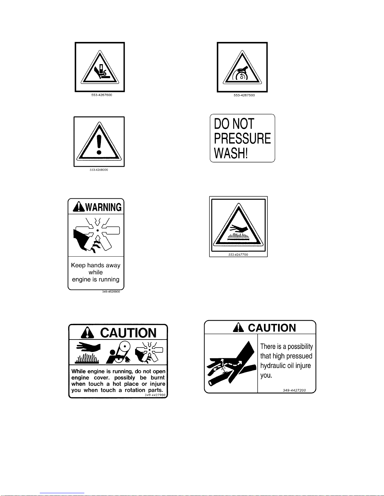
2-34
(9) Pinch caution (553-4267600) (10) Winch caution (For winch) (553-4267500) (2 places)
(11) Warning (553-4268000) (2 places) (12) Washing caution (350-4539700)
(13) Rotating fan caution (349-4526900) (14) High temperature caution (553-4267700)
(15) Engine cover caution (349-4427900) (16) High pressure oil caution (349-4427200)
Page 59
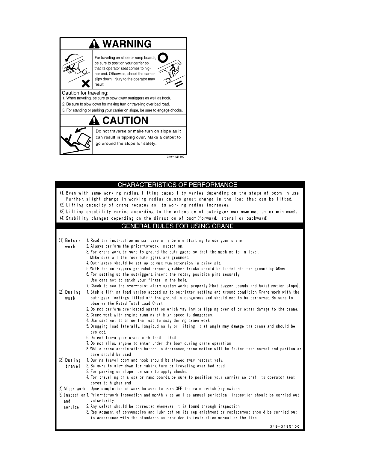
2-35
(17) Caution when traveling on slope (349-4421100)
(18) Operating caution (349-3195100)
Page 60
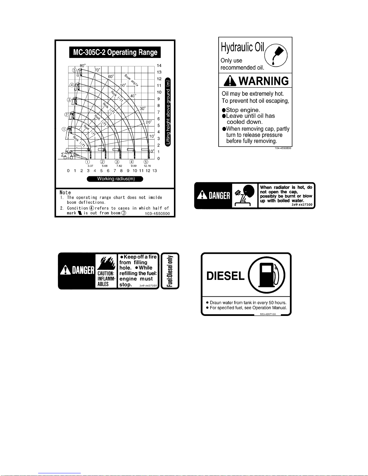
2-36
(19) Diagram of working radius and lifting height (103-4550500) (20) Hydraulic o il caution (104-4550800)
(21) Radiator caution (349-4427300)
(22) Fire ban (349-4427500) (23) Diesel fuel caution (553-4267100)
Page 61
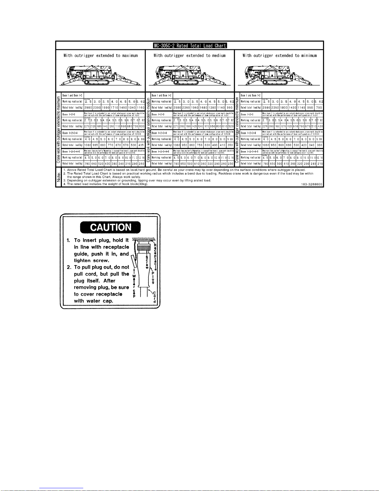
2-37
(24) Rated total load chart (103-3288600)
(25) Remote control receiver plug caution (300-4214000)
Page 62
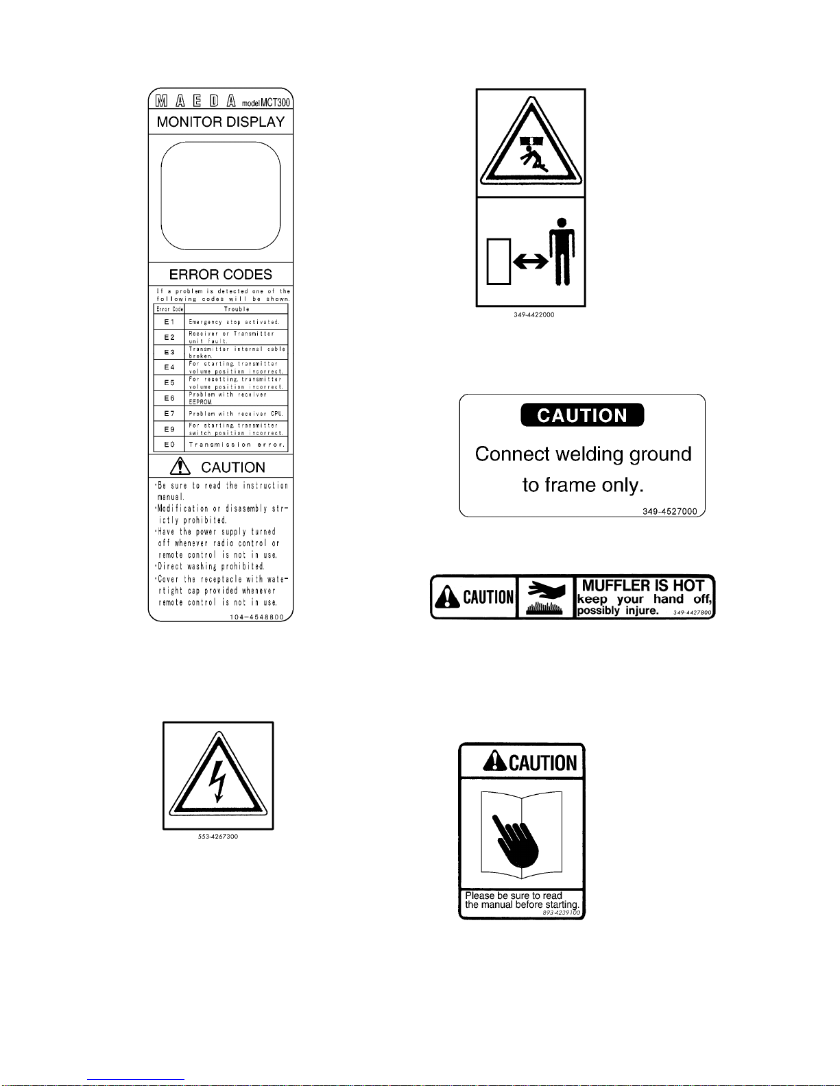
2-38
(26) Precautions for remote control (104-4548800) (27) No access to crane (349-4422000)
(28) Welding ground connection caution
(349-4527000)
(29) High temperature caution (349-4427800)
(30) Electric shock caution (553-4267300) (31) Caution when driving, inspecting or maintaining
(893-4239100)
Page 63
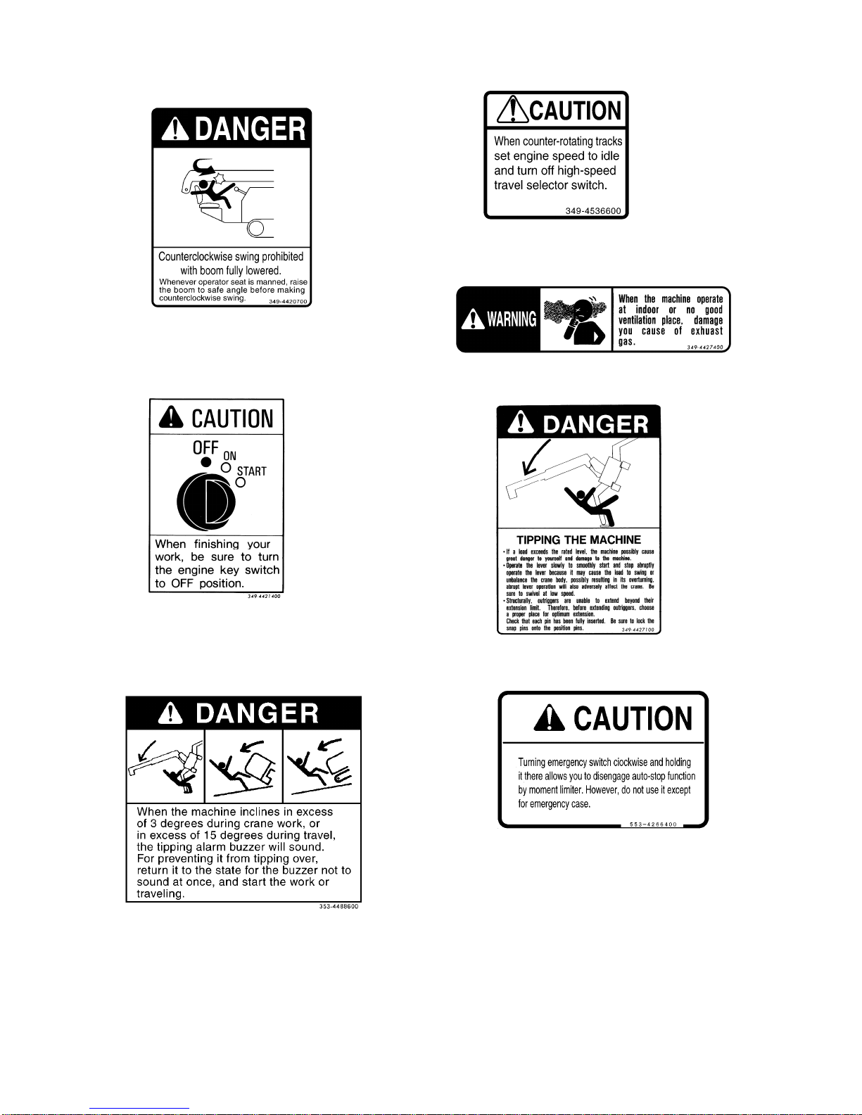
2-39
(32) Don't swing counterclockwise when fully lowered (33) Spin turn caution (349-4536600)
(349-4420700)
(34) Exhaust gas caution (349-4427400)
(35) Main switch caution (349-4421400) (36) Precaution for crane handling (349-4427100)
(37) Slope caution (353-4488600) (3 8) Caution on emergency stop cancel (553-4266400)
Page 64
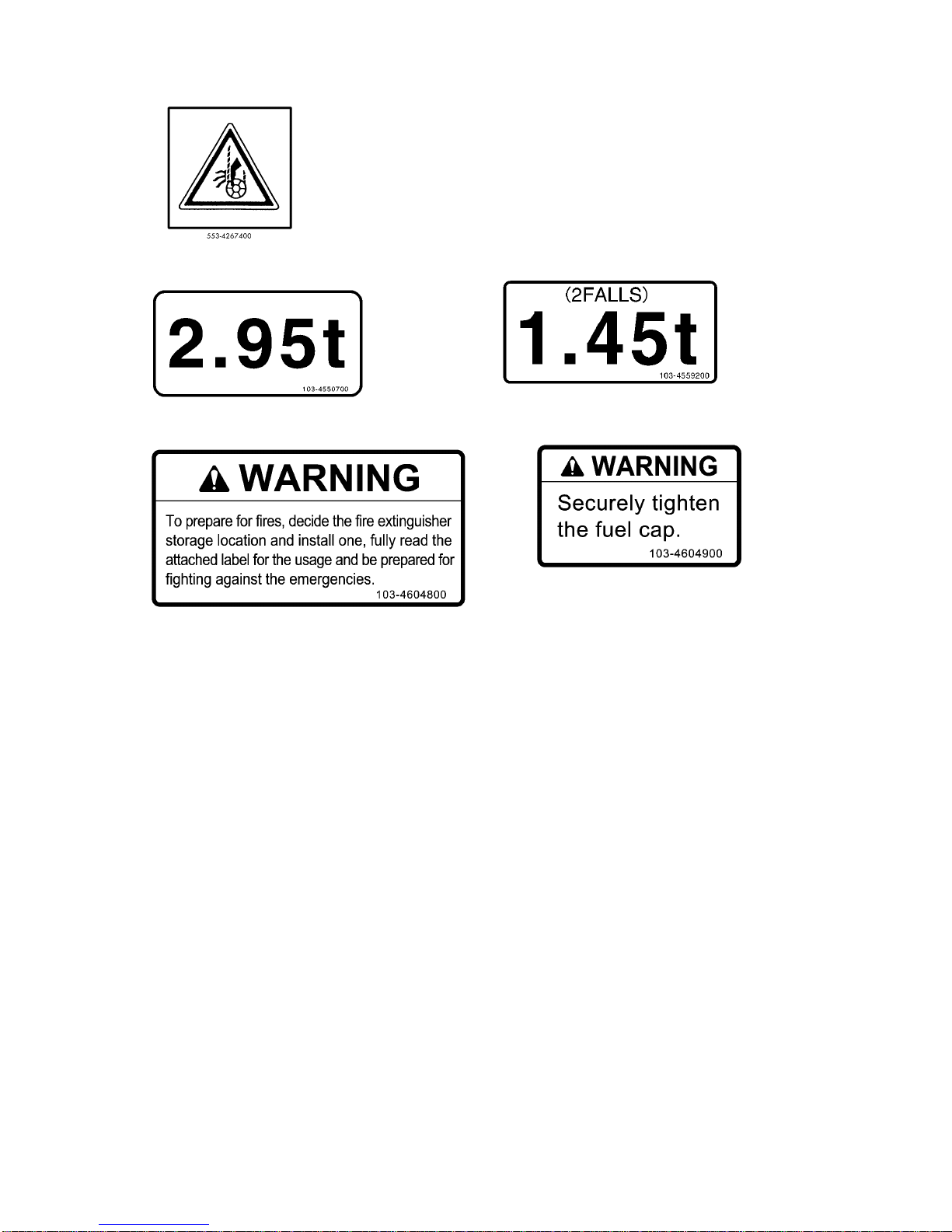
2-40
(39) Hook block caution (For hook block) (553-4267400) (2 places)
(40) 4-sling hoisting load (103-4550700) (2 places) (41) 2-sling hoisting load (103-4559200) (2 places)
(42) Fire extinguisher caution (103-4604800) (43) Fuel tank cap caution (103-4604900)
Page 65
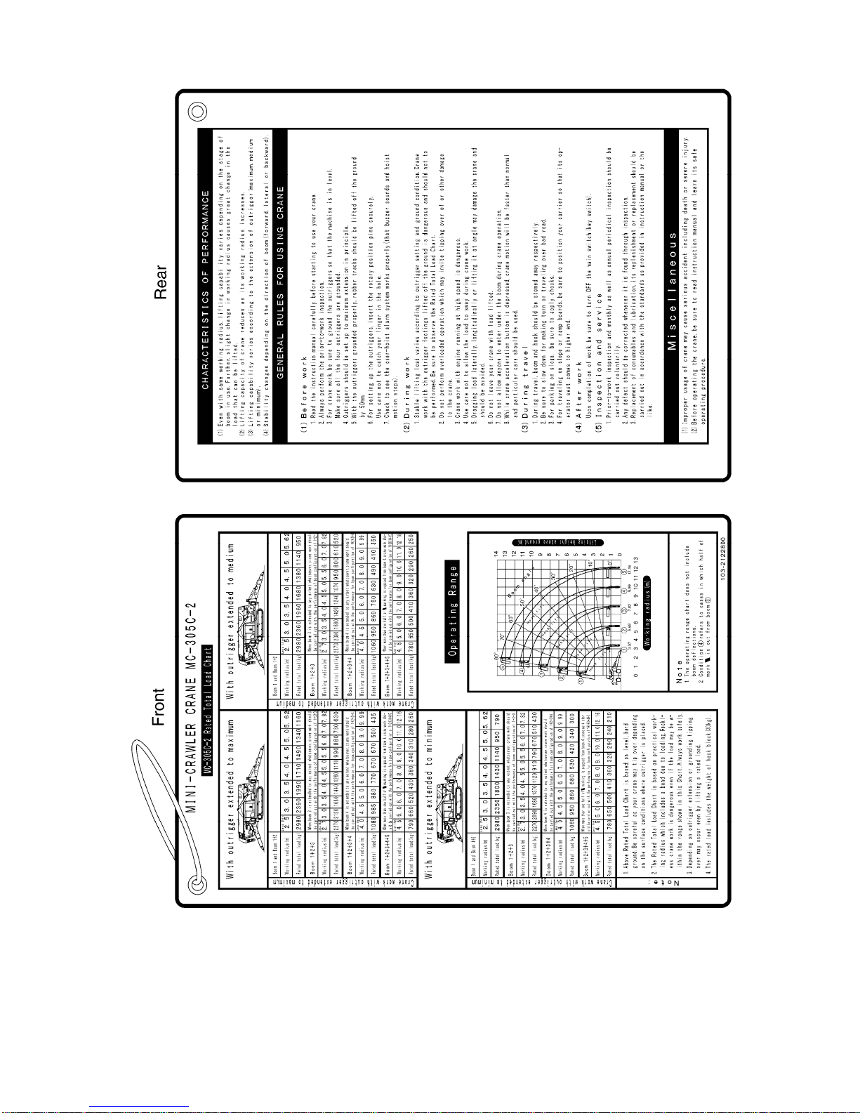
2-41
(44) Precautions for use (portable card) (103-2122800)
Page 66
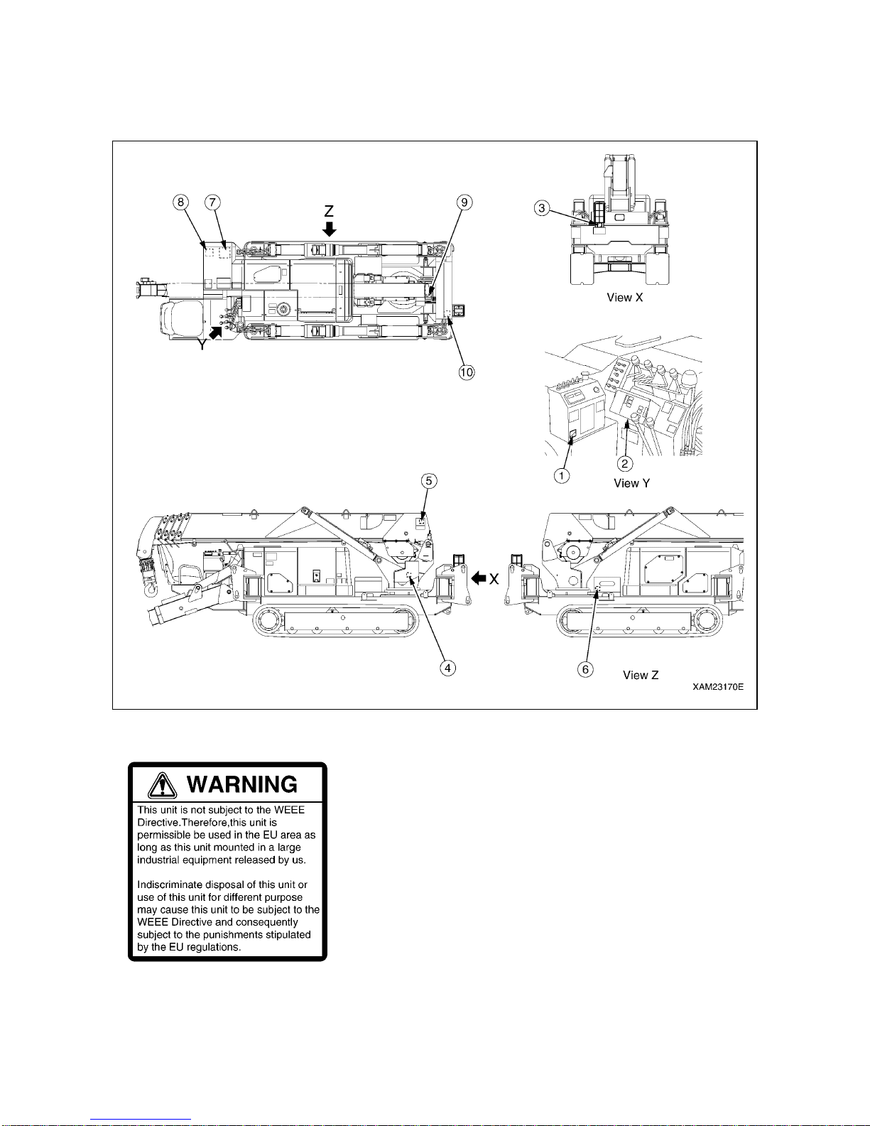
2-42
7. WEEE DIRECTIVE LABEL LOCATIONS
Keep these labels clean all the time.
When replacing electrical equipment on which this label is affixed, always apply a new label.
[WEEE DERECTIVE LABEL (104-4549500)]
[LOCATIONS OF WEEE DIRECTIVE LABELS]
(1) Side of the instrument panel
(2) Side of the moment limiter display
(3) Lower side of the workin g st atus lamp
(4) Side of the moment limiter converter
(5) Side of the boom angle detector
(6) Side of the battery
(7) Top of the remote-controlled receiver
(8) Side of the speaker
(9) Side of the boom length detector
(10) Side of the inclination sensor
(11) Side of the remote-controlled transmitter
(no illustration)
Page 67

3-1
OPERATION
1. MACHINE EACH SECTION 3- 2
2. OPERATIONS 3-40
3. HANDLING RUBBER TRACKS 3-102
4. HANDLING WIRE ROPES 3-106
5. TRANSPORTATION 3-108
6. HANDLING IN COLD WEATHER 3-111
7. LONG-TERM STORAGE 3-113
8. HANDLING BATTERY 3-114
9. TROUBLESHOOTING 3-119
Page 68
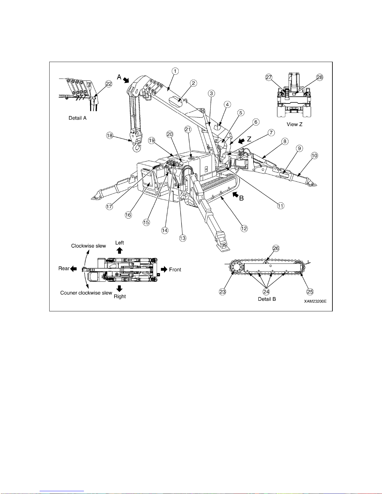
3-2
1. MACHINE EACH SECTION
1.1 MACHINE EACH UNIT
(1) Boom
(2) Boom telescoping cylinder (Inside the boom)
(3) Boom derricking cylinder
(4) Load indicator
(5) Winch
(6) Post
(7) Moment limiter converter
(8) Outrigger setting cylinder
(9) Outrigger extension cylinder (Built in the box)
(10) Outrigger
(11) Slewing device
(12) Rubber track
(13) Traveling operation unit
(14) Crane operation unit
(15) Moment limiter display unit
(16) Operation seat
(17) Instrument panel
(18) Hook block
(19) Hydraulic oil tank (Inside machinery cover)
(20) Outrigger un-set warning lamp
(21) Fuel tank (Inside machinery cover)
(22) Over hoist detector
(23) Traveling motor and sprocket
(24) Track roller
(25) Idler
(26) Carrier roller
(27) Working status la mp
(28) Headlight
Page 69
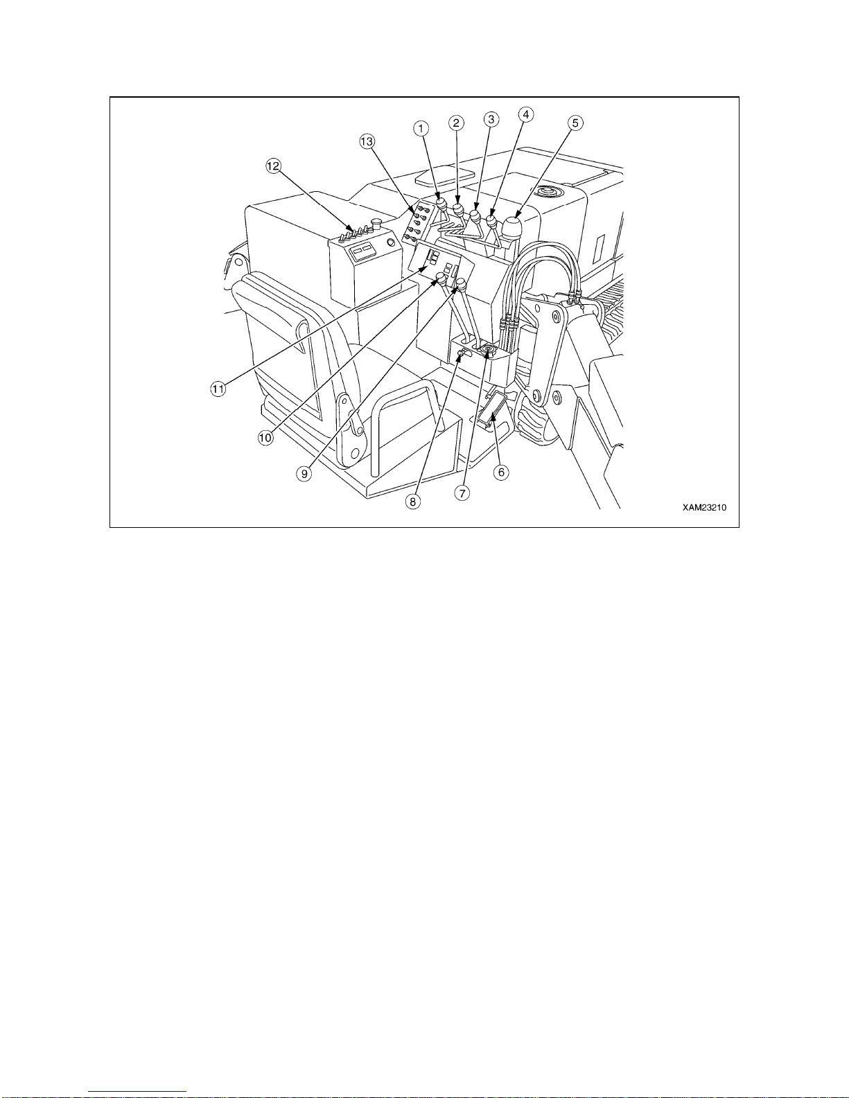
3-3
1.2 TRAVELING AND CRANE OPERATION UNITS
(1) Slewing lever
(2) Boom telescoping lever
(3) Winch lever
(4) Boom derricking lever
(5) Outrigger un-set warning lamp
(6) Acceleration pedal
(7) Level
(8) Traveling lock lever
(9) Right traveling lever
(10) Left traveling lever
(11) Moment limiter display panel
(12) Instrument panel
(13) Outrigger operation panel
Page 70
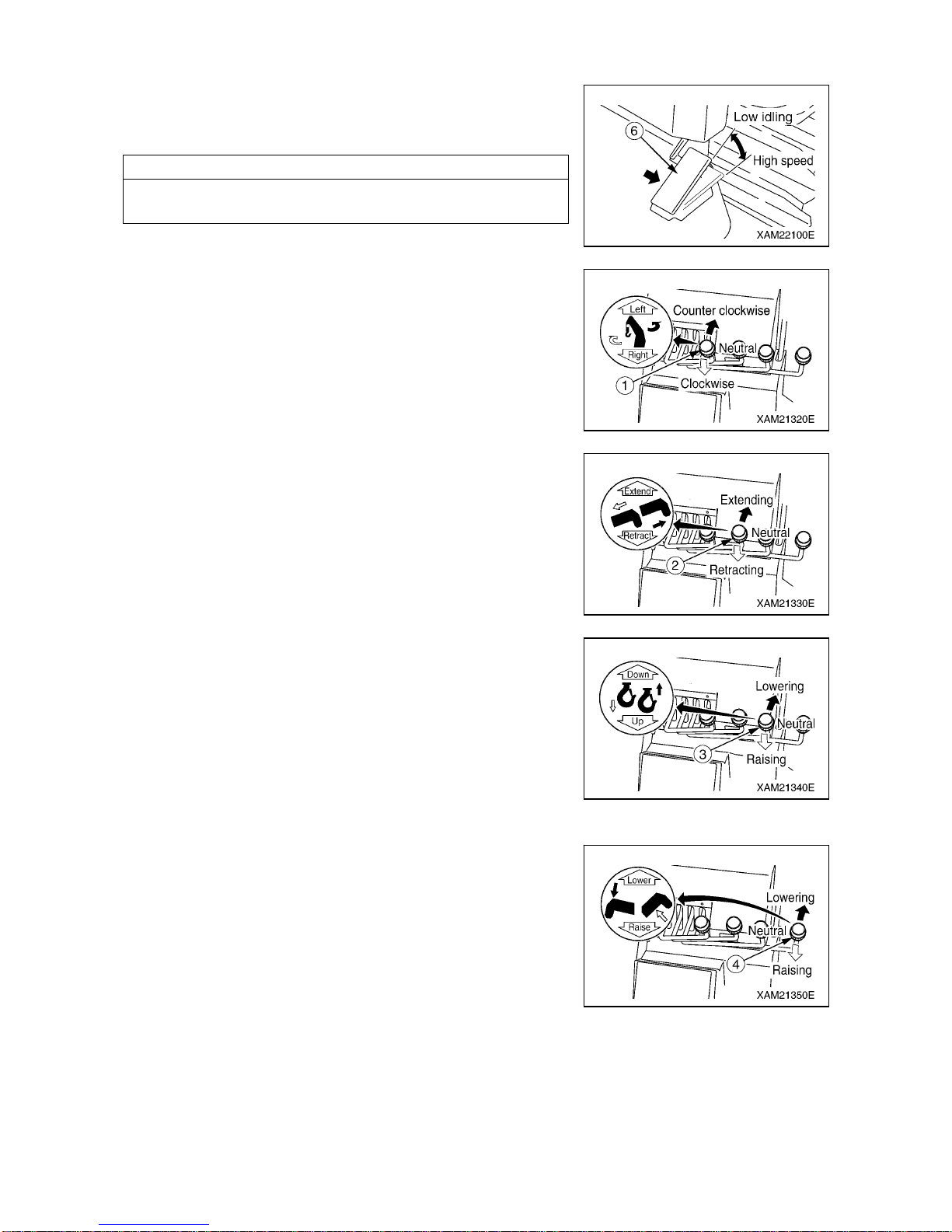
3-4
[1] ACCELERATION PEDAL (6)
Use the pedal to adjust the engine speed or output.
• Low idling: Release your foot from the pedal.
• Full speed: Press down fully on the acceleration pedal.
NOTES
Press down on the acceleration pedal to the position necessary
for the work.
[2] SLEWING LEVER (1)
Use the lever to slew the crane boom and post.
• Slew counter clockwise: Press the lever forward (Left).
• Neutral: Release your hand from the lever.
The lever returns to the ”NEUTRAL” position and the
slewing stops.
• Slew clockwise: Pull the lever toward you (Right).
[3] BOOM TELESCOPING LEVER (2)
Use this lever for telescoping the crane boom.
• Extend: Push the lever forward (Extend).
• Neutral: Release your hand from the lever.
The lever returns to the ”NEUTRAL” position and the
boom telescoping stops.
• Retract: Pull the lever toward you (Retract).
[4] WINCH LEVER (3)
Use this lever to raise/lower the hook block of the crane.
• Lower: Push the lever forward (Down).
• Neutral: Release your hand from the lever.
The lever returns to the ”NEUTRAL” position and the
machine automatically brakes. The lowering/raising of the
hook block stops.
• Raise: Pull the lever toward you (Up).
[5] BOOM DERRICKING LEVER (4)
Use this lever to raise/lower the hook block of the crane.
• Lower: Push the lever forward (Lower).
• Neutral: Release your hand from the lever.
The lever returns to the ”NEUTRAL” position and the
boom derricking stops.
• Raise: Pull the lever toward you (Raise).
Page 71
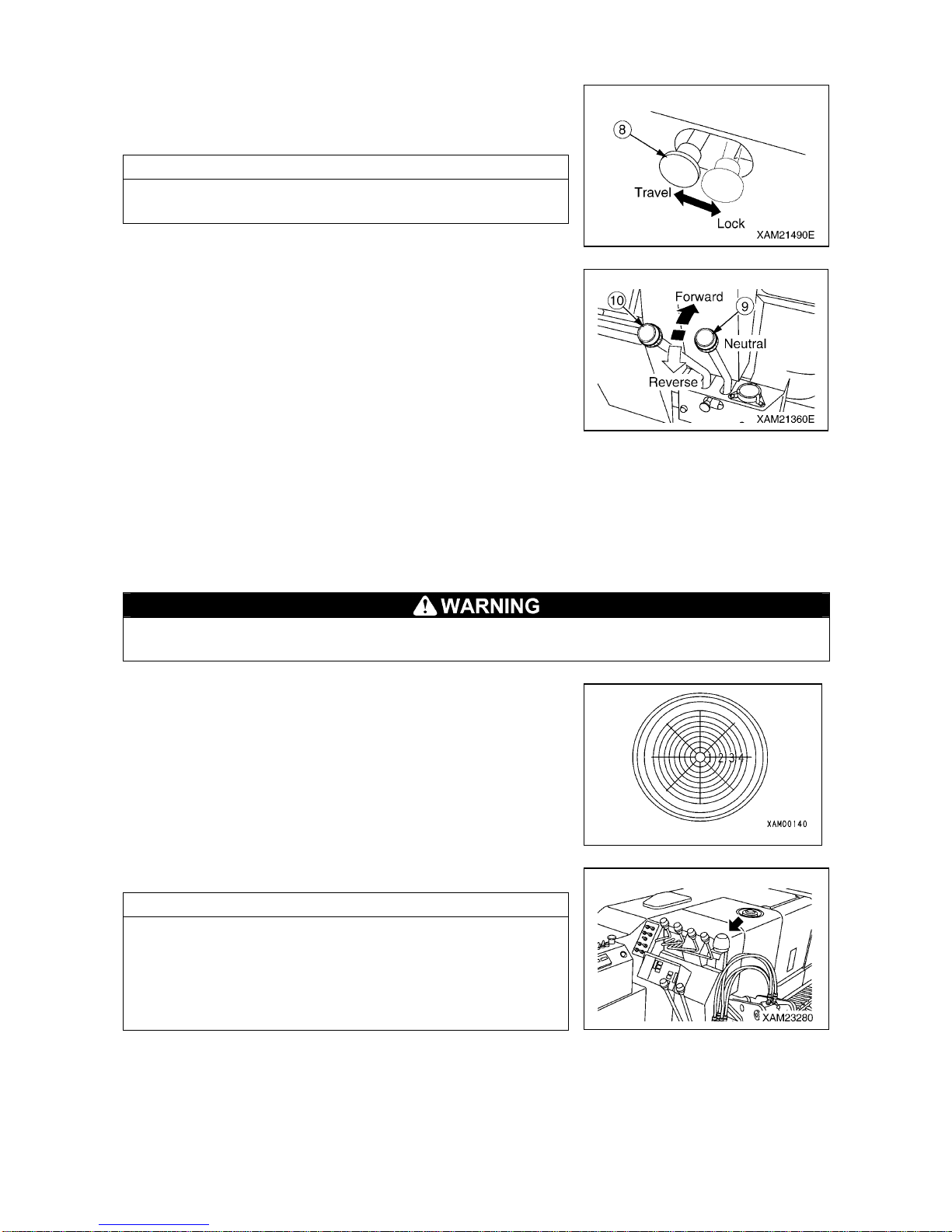
3-5
[6] TRAVELING LOCK LEVER (8)
Use this lever to “lock” the traveling levers.
• Lock: Push the lever to the right.
• Travel: Push the lever to the left.
NOTES
Operate the traveling lock lever while the left and right traveling
levers are at the “NEUTRAL” position.
[7] LEFT/RIGHT TRAVELING LEVER (9), (10)
Use these levers to move the machine forward/backward, stop,
slew, and to adjust the traveling speed.
• Forward: Push the left and right levers forward at the same time.
• Neutral: Release your hands from left and right levers at the
same time. The levers return to the “NEUTRAL”
position and the machine automatically brakes and
stops at that position.
• Backward: Pull the left and right levers toward you at the same time.
• Left turn: Release your hand from the left lever and operate the right lever forward or backward.
• Right turn: Release your hand from the right lever and operate the left lever forward or backward.
• Spin turn: Operate the left and right levers to the o pposite direction. The left and right cra wlers turn to the
opposite direction, allowing you to make the spin turn.
[8] LEVEL
When installing the outrigger, make adjustments while looking at the level so that the machine
body will be leveled. Performing the crane operation with the body tilted will cause overturning.
This device indicates how much the machine body is tilted.
The bubble position shows how much the machine is tilted in
which direction.
Use this device to verif y that the m achine is leveled when setting
the outriggers.
[9] OUTRIGGER UN-SET WARNING LAMP (Red)
The lamp flashes if one of the four outriggers is not set properly.
NOTES
• If the extension or setting of one of the four outriggers cannot
be detected, the outrigger un-set warning lamp flashes.
• The outrigger un-set warning lamp is linked with the working
status lamp for moment limiter (red). As the outrigger un-set
warning lamp flashes, the working status lamp (red) also
rotates and lights up.
Page 72
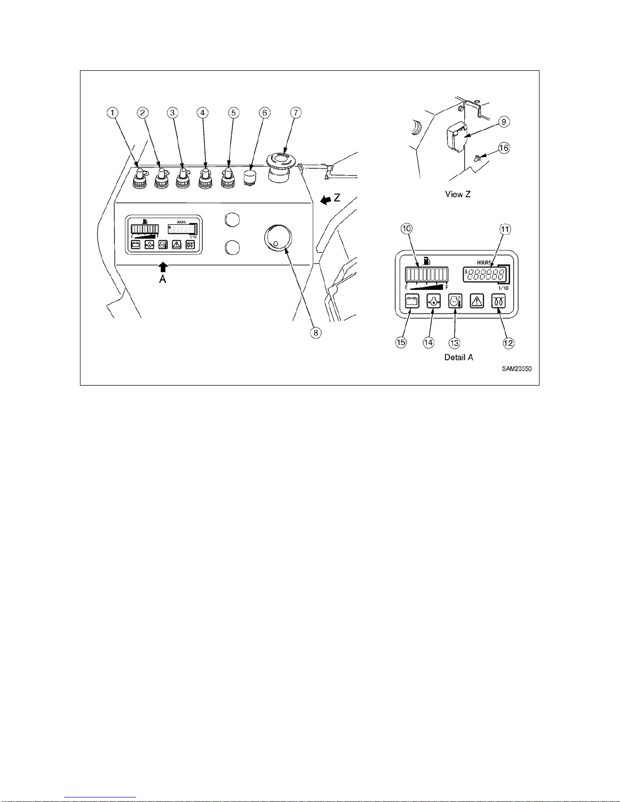
3-6
1.3 INSTRUMENT PANEL SECTIONS
(1) Headlight switch
(2) Crane high-speed switch
(3) Hook stowing switch
(4) Traveling high-speed switch
(5) Boom stowing switch
(6) Horn switch
(7) Engine emergency stop switch
(8) Starter switch
(9) Emergency stop cancel switch
(10) Fuel gauge
(11) Hour meter
(12) Pre-heat monitor
(13) Engine water temperature monitor
(14) Engine oil pressure monitor
(15) Battery charge monitor
(16) Boom lift bypass switch
Page 73
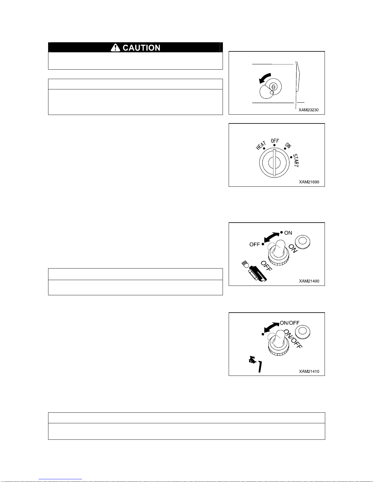
3-7
1.3.1 DESCRIPTION OF EACH SWITCHES
[1] STARTER SWITCH
Always turn the starter switch to the “OFF” position after
completing the work.
NOTES
When inserting the key for the starter switch, slide the cover to
the left so that you can see the keyhole of the switch, and t hen
insert the key.
Use this switch to start and stop the engine.
• HEAT : Turn the key to this position when starting the engine in
the cold weather.
• OFF : You can inse rt/remove the key at this position. All the
switches in the electrical system are turned off and the
engine stops.
• ON : Electricity runs into all the circuits.
• START: When the engine has started, release your hand from the
key. The key automatically returns to t he “ON” pos ition.
[2] HEADLIGHT SWITCH
Use this switch to turn on t he headlights on front of the machine.
The pilot lamp at the switch section lights up when the switch is set
to the “ON” position and extinguishes at the “OFF” position.
• ON: Push the switch forward. The headlights turn on.
• OFF: Push the switch toward you. The headlights turn off.
NOTES
The headlights do not light up even if the headlight switch is
operated when the starter switch is at the “OFF” position.
[3] CRANE HIGH-SPEED SWITCH
Use this switch to change the operating speed of the crane during
the crane operation.
The pilot lamp at the switch section lights up when t he switch is
operated to the “ON” position and extinguishes at the “OFF”
position.
• ON: Push the switch forward, and when the pilot lamp lights up
the switch turns "ON" and the crane operating speed
increases.
• OFF: Push the switch forward again, and when the pilot lamp
goes off the switch turns "OFF" and the crane operating
speed returns to normal.
NOTES
Always set the work selector switch on the outrigger operation panel to the “CRANE” position. If the
work selector switch is at other position than “CRANE”, the crane high-speed switch does not work.
Page 74
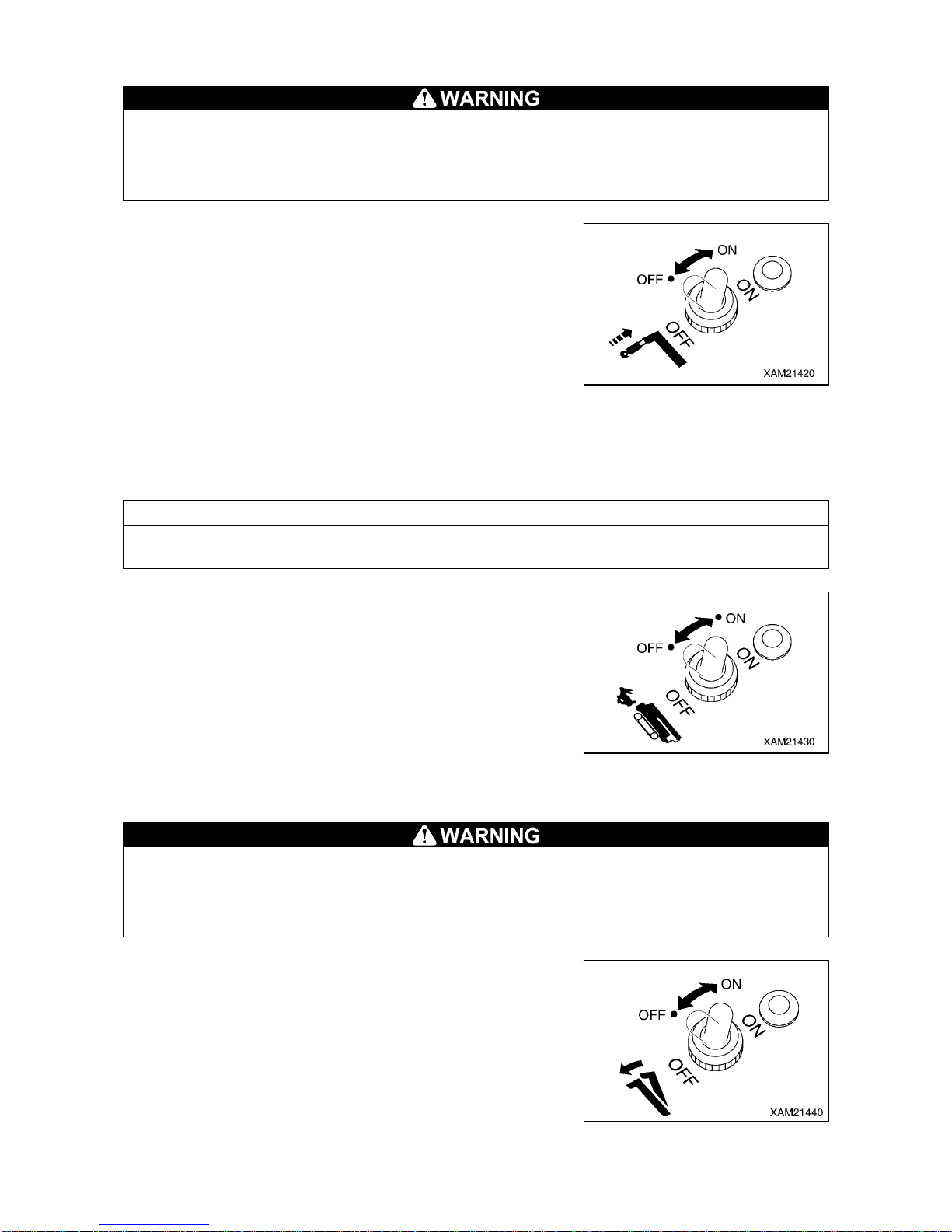
3-8
[4] HOOK STOWING SWITCH
• The hook stowing switch cancels the auto-stop function of the over hoist detector.
Operate the winch lever carefully when stowing the hook block. Pay sufficient attention not to
let the hook block collide with the boom.
• Use this switch only when stowing the hook block .
Use this switch to stow the hook block at the tip of the boom. The
pilot lamp at the switch section lights up when the switch is
operated to the “ON” position and extinguishes at the “OFF”
position.
• ON: Keep pushing the switch forward and operate the win ch lever
to “RAISE” side. The hook block is raised and can be
stowed in the tip of the boom.
• OFF: Release your finger from the switch. The switch returns to
the original position and the auto-stop function of the over
hoist detector will be activated.
[5] TRAVELING HIGH-SPEED SWITCH
NOTES
It may be difficult to change the direction in the high-speed traveling mode. In that case, switch to the
low-speed traveling mode.
Use this switch to change the mode of the machine traveling speed.
The pilot lamp at the switch section lights up when the switch is
operated to the “ON” position and extinguishes at the “OFF”
position.
• ON: Push the switch forward. The traveling speed mode changes
to high-speed traveling mode.
• OFF: Push down the switch toward you. The traveling speed
mode changes to low-speed traveling mode.
[6] BOOM STOWING SWITCH
• The boom stowing switch cancels the auto-stop function of the lower-limit detecting interlock
device during the boom “lowering” operation.
Operate the boom derricking lever carefully when stowing the boom. Pay sufficient attention
not to let the boom collide with the machine body.
• Use the boom stowing switch only when stowing the boom.
Use this switch to stow the boom.
The pilot lamp at the switch section lights up when the switch is set
to the “ON” position and extinguishes at the “OFF” position.
• ON: Keep pushing the switch forward and operate the boom
derricking lever to “LOWER” side. The boom lowers and
can be stowed.
• OFF: Release your finger from the switch. The switch returns to
the original position and the auto-stop function of the
lower-limit detecting interlock device will be activated.
Page 75
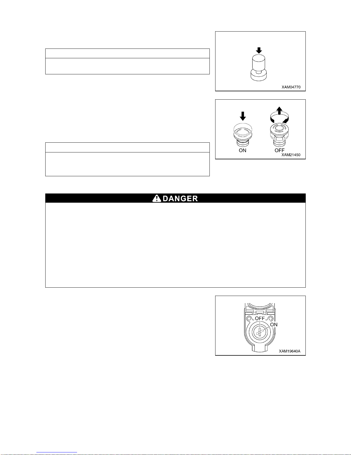
3-9
[7] HORN SWITCH
Use this switch to honk the horn.
• Honking the horn: Press the switch.
NOTES
The horn will stop when you release your finger from the switch .
[8] ENGINE EMERGENCY STOP SWITCH
Use this switch in case of an error in the machine to stop the
machine for emergency.
• ON: Press the switch. The engine stops.
• OFF: Turn the switch clockwise (direction of the arrow in the right
figure). The switch returns to the original po si tion.
NOTES
When restarting the engine after emergency stop, be sure to turn
the engine emergency stop switch to the “OFF” position before
starting the engine.
[9] EMERGENCY STOP CANCEL SWITCH
• Do not set the emergency stop cancel switch to ON (cancel) position during crane work.
Such attempt prevents automatic stop from occurring even under over wound condition during
crane work, thus may not only cause the hoisted load to collide and damage crane parts but
may cause the load to drop and cause a serious accident or cause the machine to tip over.
Keep the switch key extracted during normal crane works.
• Do not turn the emergency stop cancel switch to the “ON” (cance l) position when stowing the
hook.
The winch wire rope may be cut causing the hook to fall or damage on the boom.
Use the hook stowing switch when stowing the hook.
• Do not turn ON (cancel) the emergency stop cancel switch unless you find an error or
check/perform maintenance on detectors.
When turning ON (cancel) the emergency stop cancel switch, always shift the crane speed to
low.
Use the emergency stop cancel switch as needed when
performing inspection or maintenance to clear the activation stop.
Open the cover when using the switch.
• ON (Clear): Insert the key into the switch. Turn the key clockwise
and retain the key at that position. The activation
stop function is cleared while the key is maintained at
the ON position.
• OFF (Auto): Insert the key into the switch and turn the key
counterclockwise. The activation stop functions.
The key can be removed or inserted at this position.
Page 76
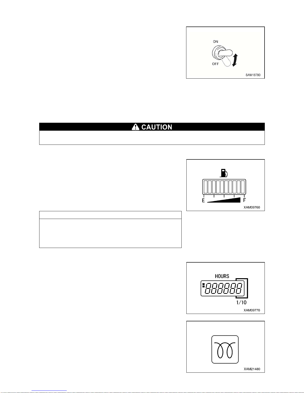
3-10
[10] BOOM LIFT BYPASS SWITCH
Use this switch to raise the boom in overload condition.
ON : Keep pushing the switch upward. This relea ses boom raise
restriction under overload condition and you can raise the
boom.
OFF : Rele ase your finger f rom the switch. T he switch returns to
the original position and the auto-stop function of boom
raise under overload condition will be activated.
Refer to the ”OPERATION 1.6.3 MOMENT LIMITER
OPERATION” for more information about how to use this switch.
1.3.2 DESCRIPTION OF EACH MONITORS
If the monitor flashe s during the work, stop the operation immediately and check, adjust, or
repair the relevant section.
[1] FUEL GAUGE
This gauge indicates the remaining amount of the fuel in the fuel
tank.
Turn the starter switch to the “ON” position and the gauge indicate s
the remaining amount of the fuel with the “bar”.
When only one “bar” lights up on the “E” side, there is not much
fuel left.
Stop the operation immediately and refuel.
NOTES
• At the end of a day, fuel to full (until all the “bar”s (10 bar s) light
up.)
• The remaining amount indicated may not b e corr ect for a wh ile
after the starter switch is turned to the “ON” position. This is
normal.
[2] HOUR METER
This meter shows the total running hours of the machine.
Use this value as the reference for periodical check interval.
If the engine is in operation, the meter indication advances even if
the machine is not moving.
The meter indication advances for “1” when the machine has been
running for 1 hour regardless of the engine rotation speed.
[3] PREHEAT MONITOR
The monitor lights up during the preheating operation when
starting the engine.
It lights up when the starter switch is operated to the “HEAT”
(preheat) position and goes off in several seconds to indicate the
completion of preheating.
Page 77
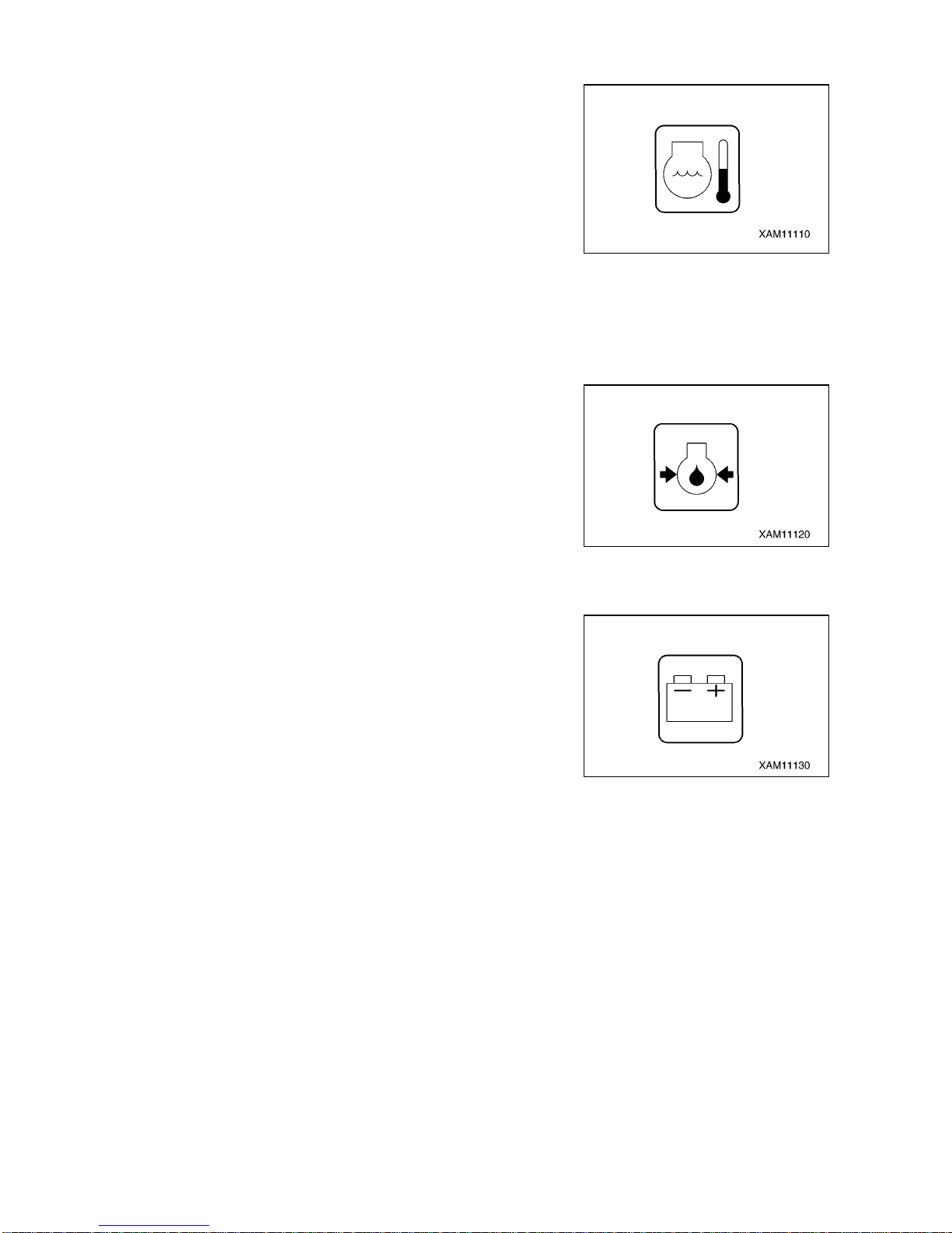
3-11
[4] ENGINE WATER TEMPERATURE MONITOR
This monitor indicates errors with the engine cooling water
temperature.
The temperature is normal if this monitor is OFF during the
operation.
If it lights up during the operation, it means that the engine cooling
water temperature exceeded the normal temperature.
Promptly switch the engine rotation to low idling and wait until the
monitor goes off (engine cooling water temperature goes down).
Then, stop the operation and check the water leakage from the
radiator, clogging in the radiator core, and damage and tension of
the alternator belt.
[5] ENGINE OIL PRESSURE MONITOR
This monitor indicates the drop in the engine oil pressure.
If it lights up when the starter switch is turned to the “ON” position
and goes off as the engine rotation increases after the engine is
started, the engine oil pressure is normal.
If it lights up during the operation, the engine oil pressure has
dropped.
Immediately stop the machine and check the clogging of the
engine oil filter and engine lubricant level.
[6] BATTERY CHARGE MONITOR
This monitor indicates errors in the battery charge system.
If it lights up when the starter switch is turned to the “ON” position
and goes off as the engine rotation increases after the engine is
started, the battery charge system is normal.
If it lights up during the operation, there is an error in the battery
charge system.
Immediately stop the machine and check the tension of the
alternator belt.
Page 78
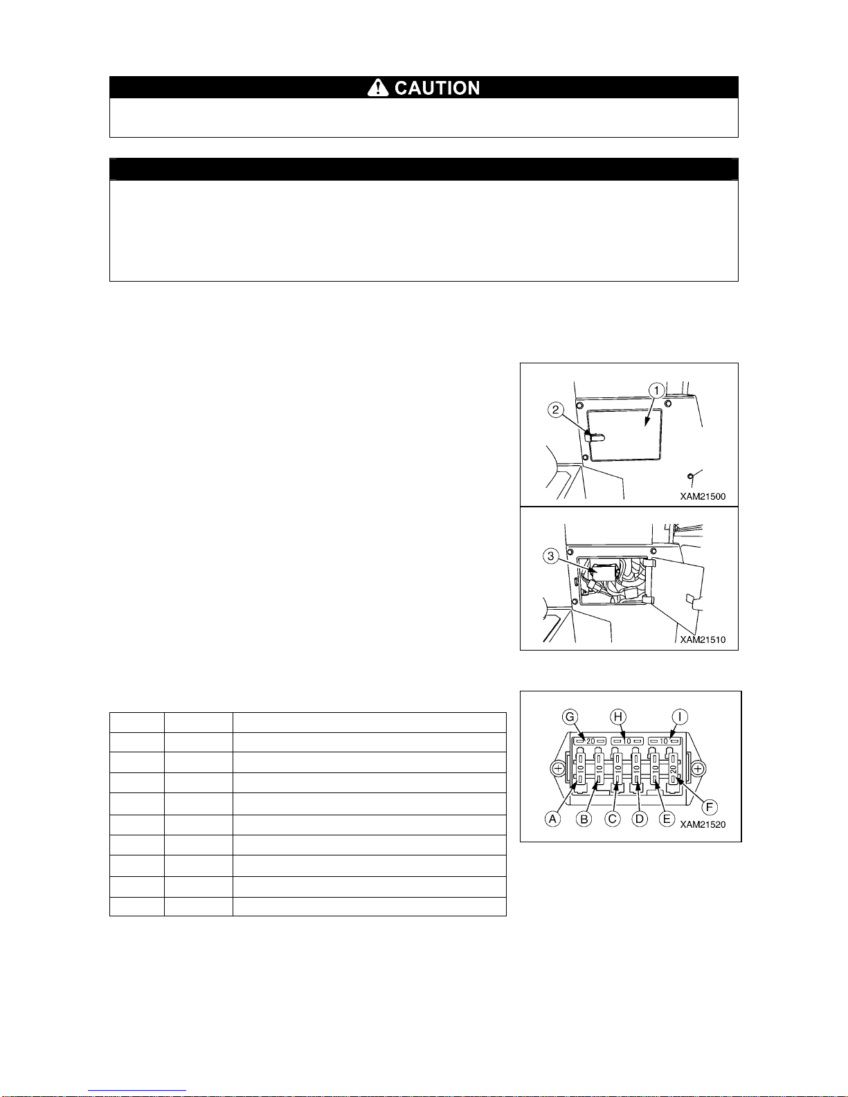
3-12
1.3.3 DESCRIPTION OF FUSES
Be sure to turn the starter switch to the “OFF” position when checking or replacing a fuse.
CAUTION
Fuses protect electrical components and wires from being burnt out.
• Fuses are blade fuses. If a fuse was corroded and shows white powder, be sure to change the
fuse.
• If a fuse has melt down, always check the cause in the circuit and repair the problem before
changing the fuse.
• Always use a fuse of the same capacity when replacing one.
The fuse box is provided at the lower section of the instrument
panel.
Check and replace a fuse using the procedure below.
1. Remove the buckle (2) of the cover (1) at the bottom of the
instrument panel to open the cover (1).
2. Remove the cover (3) of the fuse box.
3. Remove the fuse from the fuse box and check/replace the fuse.
4. Insert a new or checked fuse to the original position in the fuse
box.
[FUSE CAPACITY AND CIRCUIT NAMES]
The table below shows the fuse system and its capacity.
Index Capacity Circuit Name
A 10 A Main P.S.
B 10 A PCB
C 10 A Engine control
D 10 A Solenoid valve
E 10 A Horn, light
F 20 A Moment limiter, remote controller
G 20 A Spare
H 10 A Spare
I 10 A Spare
Page 79
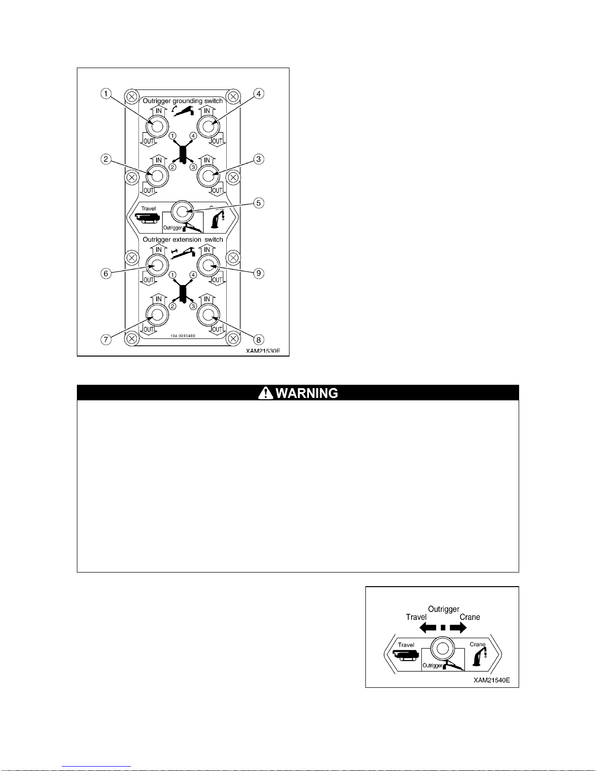
3-13
1.4 OUTRIGGER OPERATION PANEL
(1) Outrigger (1) setting switch
(2) Outrigger (2) setting switch
(3) Outrigger (3) setting switch
(4) Outrigger (4) setting switch
(5) Work selector switch
(TRAVEL, OUTRIGGER, CRANE)
(6) Outrigger (1) extension switch
(7) Outrigger (2) extension switch
(8) Outrigger (3) extension switch
(9) Outrigger (4) extension switch
[1] WORK SELECTOR SWITCH (TRAVEL, OUTRIGGER, CRANE)
• When operating the work selector switch to the “TRAVEL” position, be sure to stow the crane
and put the machine in the “traveling posture”. Driving the machine not in the “traveling
posture” can overturn the machine, resulting in serious accidents.
• Be sure to operate the traveling lock lever to the “LOCK” position before outriggering or crane
operation.
Note that if the traveling lock lever is not at the “LOCK” position, you can still travel the
machine even if the work selector switch is operated to the “OUTRIGGER” or “CRANE”
position. Be careful not to let your hand or body touch the traveling levers. The machine may
move, causing serious accidents.
• Be sure to set all the outriggers when turning the work selector switch to the “CRANE”
position to perform the crane operation. Inappropriate setting of outriggers will prevent the
crane operation because of the outrigger safety device function.
• Always stow the boom when performing the outrigger o per atio n with the work selector switch
set to the “OUTRIGGER” position. If the boom is not stowed properl y, the outrigger safety
device function prevents the outrigger operation from being performed.
Use this switch to switch the work state of the machine
(“TRAVEL”, ”OUTRIGGER”, ”CRANE”).
• Travel: Push down the switch to the left. Now you can travel the
machine.
• Outrigger: Push down the switch to the center position. Now you
can perform the outrigger operation.
• Crane: Push down the switch to the right. Now you can perform
the crane operation.
Page 80
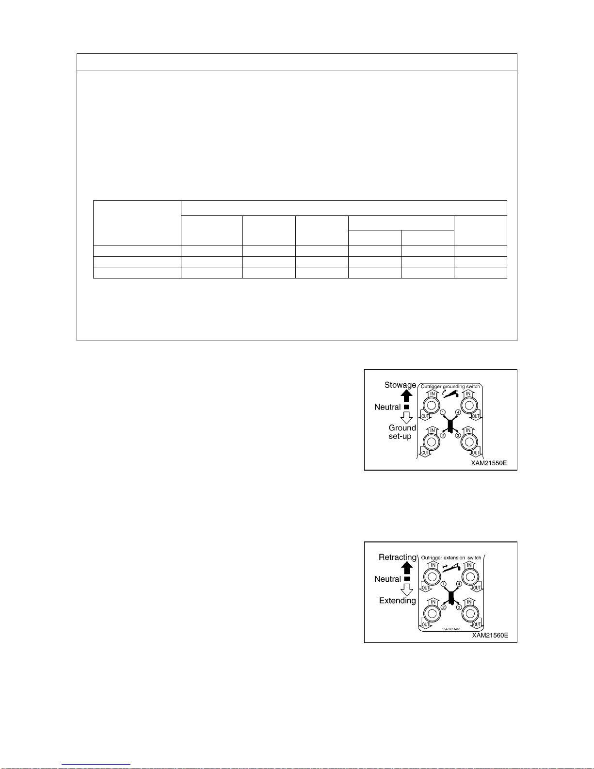
3-14
NOTES
The table below shows the relation between the operation position of the work selector switch and
permitted operations.
• Only the traveling operation is active when the work selector switch is at the “TRAVEL” position.
• When the work selector switch is at the “OUTRIGGER” position, all the devices in the table below are
active.
Be sure to set the traveling lock lever to the “LOCK” position and stow the crane when operating the
outriggers. Be careful not to touch the operation levers of the crane.
• When the work selector switch is at the “CRANE” position, all the devices except for outrigger
operation in the table below are active.
Be sure to set the traveling lock lever to the “LOCK” position and set all the outrigger s wh en operating
the crane.
[2] OUTRIGGER SETTING SWITCHES
Use these switches to set or stow the outriggers.
There are four outriggers ((1) to (4)). Each outrigger can be
operated independently or all together.
• IN : Push down the switch upward. The outrigger setting
cylinder retracts and you can stow the outrigger.
• Neutral: Release your finger from the switch. The switch returns
to the “NEUTRAL” position and the outrigger setting
cylinder stops telescoping.
• OUT: Push down the switch downward. The outrigger setting
cylinder extends and you can set the outrigger.
[3] OUTRIGGER EXTENSION SWITCH
Use these switches to extend or stow the outriggers.
There are four outriggers ((1) to (4)). Each outrigger can be
operated independently or all together.
• IN : Push down the switch upward. The outrigger extension
cylinder retracts and you can stow the outrigger inner
box.
• Neutral: Release your finger from the switch. The switch returns
to the “NEUTRAL” position and the outrigger extension
cylinder stops telescoping.
• OUT: Push down the switch downward. The outrigger extension
cylinder extends and you can extend the outrigger.
Work Selector
Switch Operation
Position
Crane System (A: Active N: Not active)
Traveling
Operation
Outrigger
Operation
Crane
Operation
Remote Controller
Moment
Limiters
Crane Outrigger
TRAVEL A N N N N N
OUTRIGGER N (Note 1) A N N A A
CRANE N (Note 1) N A A A (Note 2) A
Note 1: Operating the traveling lock lever to the “LOCK” side restricts the traveling operation.
If the lever is not operated to the “LOCK” sid e, the machine travels when a traveling lever is
operated.
Note 2: The outri
gg
er operation is enabled only when the transmitter of the remote controller is in the
Page 81

3-15
1.5 OUTRIGGER SAFETY DEVICES
1.5.1 FUNCTIONS OF OUTRIGGER SAFETY DEVICES
The outrigger safety devices have the interlock functions shown in the table below.
Interlock
Function
Description of Interlock Function
1
Outrigger
Interlock
The outrigger is not enabled if the position pin is not inserted pro perly by rotating
the outrigger rotary to extension side (outward) with the boom being stowed
(boom lowered to maximum, slewed and stored).
• Whether the boom is lowered to the maximum is verified by the detection switch
located to the post.
• Install a protrusion on the post at the boom slew and stow position and a
detector switch on the traveling dolly in order to detect whether the boom has
stopped at the slew and stow position.
2 Crane Interlock
The crane operation (telescoping, raising/lowering hook, derricking, and
slewing) is enabled only when all the four outriggers are extended and set
(overhung and grounded).
The outrigger extension status is detected as follows.
• Install a detection switch at the position pin section of the outrigger rotary to
detect the insertion of the position pin into the extension position.
• Install a detection switch inside the outrigger inner box to detect if the tray is
seated properly through the detection pin installed between the tip of the inner
box and the tray.
CAUTION
• Set the outriggers in the extension status and operate the work selector switch in the outrigger
operation panel to the “CRANE” position to enable the crane operation.
When the detection condi tion fo r setti ng one of the fou r outri gger s (see th e item 2 in th e table
above) is no more fulfilled, the working status lamp (red) rotates and lights up, and outrigger
un-set warning lamp (red) flashes.
If this state remains for 3 seconds or more, the crane interlock function is activated and the
crane operation will be disabled.
• Stow the crane and operate the wo rk selector switch on the ou trigger operation pan el to the
“OUTRIGGER” position to enable the outrigger setting and extension operations.
• If the crane operation is not enabled after operating the work selector switch on the outrigger
operation panel to the “CRANE” position even after the outrigger is being extended and set,
there may be faulty adjustment or failure in the outrigger safety device.
Please ask us or our sales service agency for repair.
Page 82
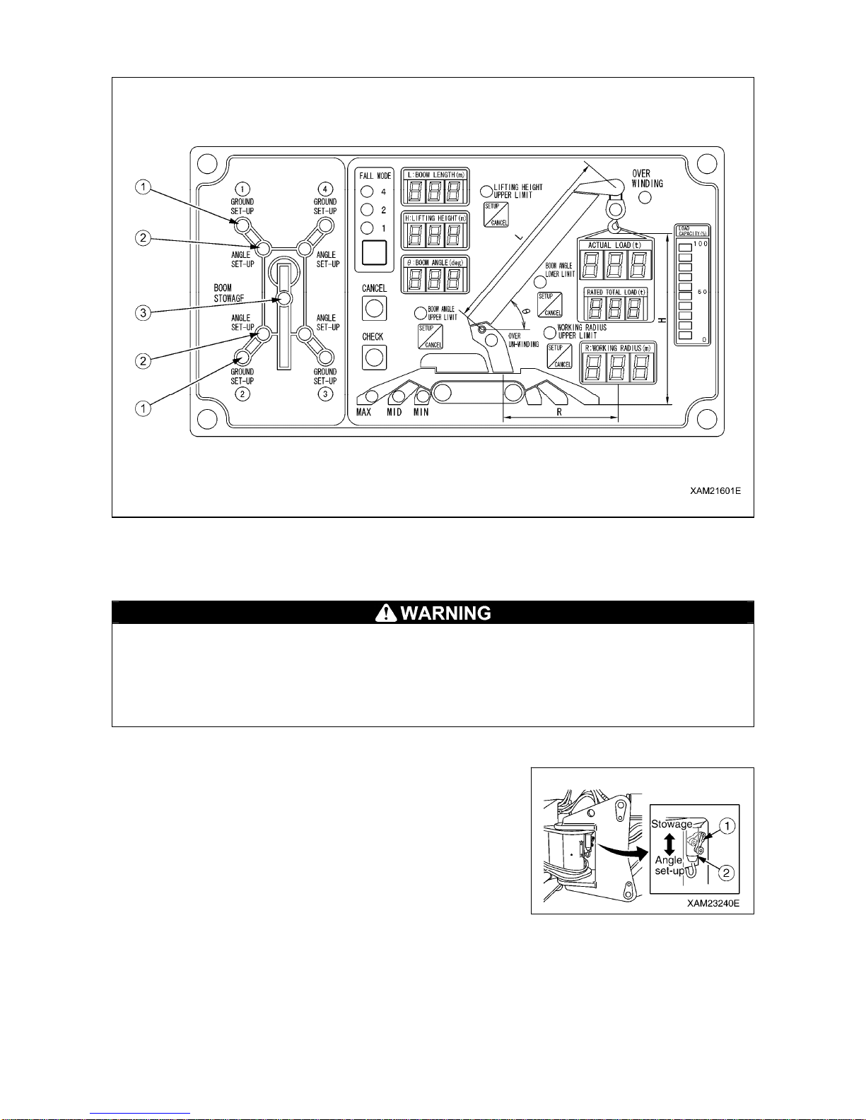
3-16
1.5.2 NAMES AND DESCRIPTIONS OF OUTRIGGER DISPLAY
(1) Outrigger setting lamp
(2) Outrigger extension lamp
(3) Boom stowing lamp
• Do not remove, disassemble, or repair detection switches. Do not move the detection s witches
from the original location to another.
• If you hit detection switches or found damage on the detection switches, be sure to check the
ON/OFF operation of the lamps on the outrigger display and operation of the crane interlock
function and outrigger interlock function. If you find any error, ask us or our sales service
agency for repair.
[1] OUTRIGGER EXTENSION LAMPS
The lamp turns on to indicate that the outrigger is extended.
Turns on when the position pin (2) is inserted (extension), and
turns off when extracted (stow).
The extraction/insertion of the position pin (2) is detected by the
detection switch (1) of the outrigger rotary.
Page 83
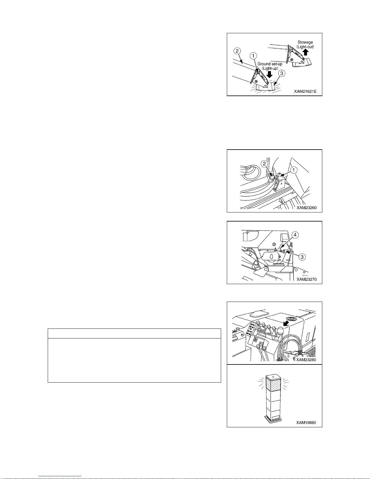
3-17
[2] OUTRIGGER SETTING LAMPS
The lamp turns on to indicate that the outrigger is set.
Turns on when the outrigger tray (3) is set, and turns off when the
tray (3) floats (stow).
The conditions of the outrigger tray (3) are detected by the
detection pin (1) at the tip of the inner box (2) and by the detection
switch inside the inner box.
[3] BOOM STOWING LAMP
This lamp turns on and indicates that the boom is stowed.
The boom stowing lamp turns on and off in accordance to the
following two types of detection switches. (When both of the
detection switches detect.)
[BOOM STOWING DETECTION IN SLEWING DIRECTION]
The lamp turns on when the boom stops at the slew and stow
position, and turns off when the boom leaves the slew and stop
position.
Boom movements are detected by the projection (2) (slew) on the
post and the detection switch (1) (fix) on the traveling dolly.
[BOOM STOWING DETECTION IN HORIZONTAL DIRECTION]
The lamp turns on when the boom stops at the horizontal stowing
position, and turns off when the boom leaves the horizontal
stowing position.
Boom movements are detected by the projection (4) (movable) at
the side of the boom rear edge and the detection switch (3) (fixed)
at the boom connection.
1.5.3 OUTRIGGER UN-SET WARNING LAMP (Yellow)
This lamp flashes to indicate that one or more of the four outrigg ers
are not properly set.
NOTES
• The outrigger un-set warning lamp flashes if extension or
setting of any of the four outriggers cannot be detected.
• The outrigger un-set warning lamp is interlocked with the
working status lamp (red) for moment limiter. As soon as the
outrigger un-set warning lamp flashes, the working status lamp
(red) also rotates and lights up.
Page 84
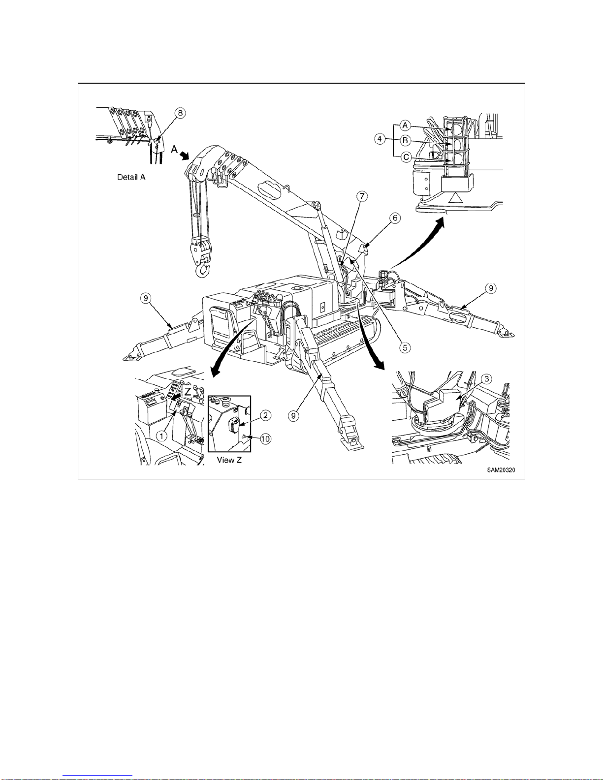
3-18
1.6 MOMENT LIMITER (OVERLOAD DETECTOR)
1.6.1 MOMENT LIMITER CONFIGURATION
(1) Moment limiter display unit
(2) Emergency stop cancel switch
(3) Moment limiter converter
(4) Working status lamp
(A) Red working status lamp (Warning lamp for
load factor of 100 % or more)
(B) Yellow working status lamp (Pre-warning
lamp for load factor of 90 to 100 %)
(C) Green working status lamp (Working lamp
for load factor of less than 90 %)
(5) Boom length gauge (inside boom)
(6) Boom angle gauge (side of boom rear edge)
(7) Pressure sensor (derrick cylinder) (two)
(8) Overwind alarm detector (side of boom tip)
(9) Outrigger position detection sw itch
(10) Boom lift bypass switch
Page 85
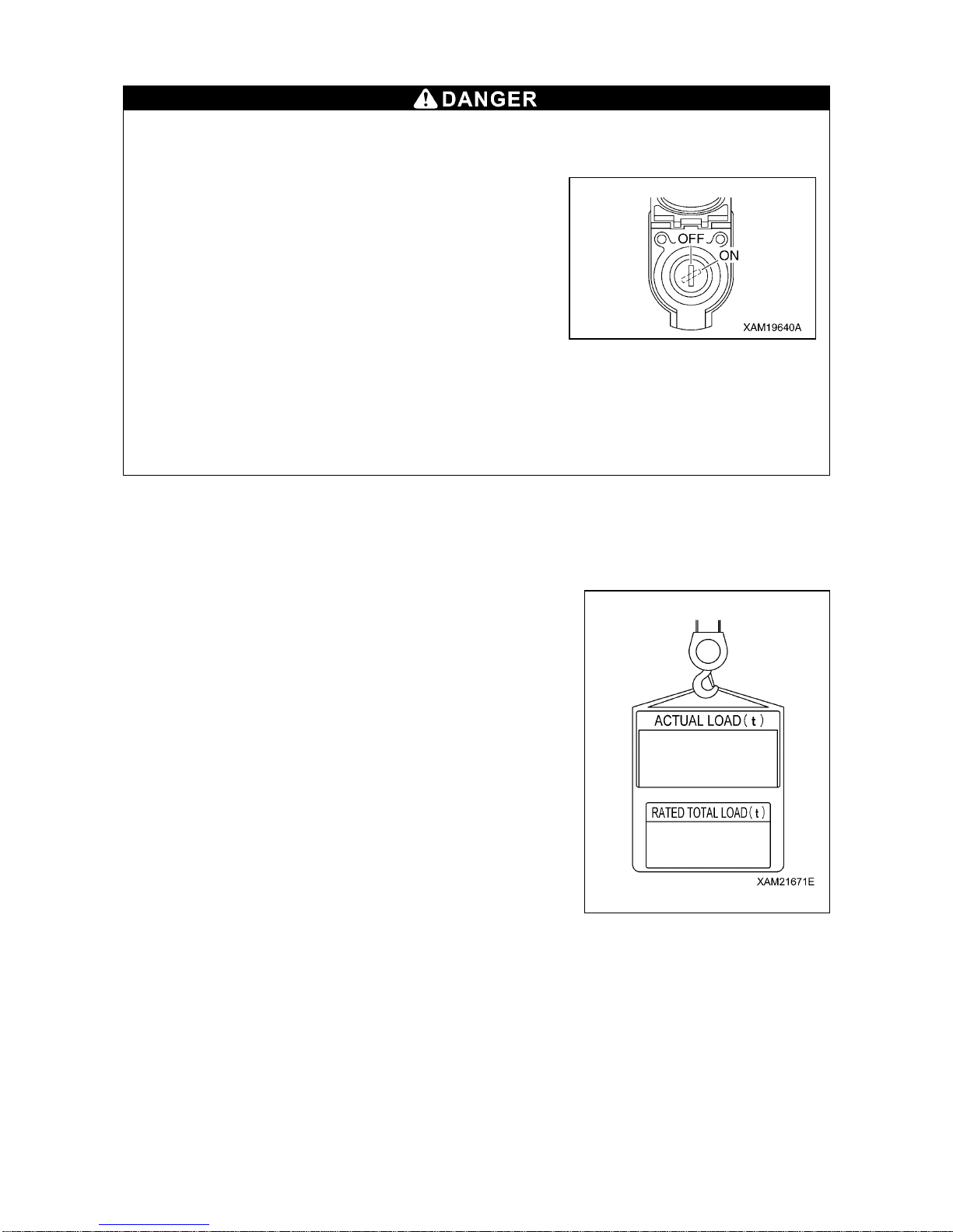
3-19
1.6.2 FUNCTION OF MOMENT LIMITER
• Do not remove, disassemble, or repair detectors. Do not move the detectors to another
location from original position.
• Should an object hit a detector or you find any damage on a detector, be sure to verify the
actuation status of the auto stop.
If you find any abnormality with the actuation of the auto
stop, do not fail to fix it.
• Do not turn ON (cancel) the emergency stop cancel
switch unless you find an error or check/perform
maintenance on detectors.
When turning ON (cancel) the emergency stop cancel
switch, always shift the crane speed to low.
Overloading can cause the hoisted load to fall, boom
breakage, or overturning of this machine that can lead to
serious accidents resulting in death or serious injury.
• The machine will not stop automatically even if the crane is overloaded during the crane
slewing operation. Do not slew the crane when being overloaded.
• When the boom approaches the stop position during the operation, be sure to change the
operation speed of the boom to low speed.
With high-speed boom operation, the boom may overrun the specified stop positio n, causing
serious accidents such as overturning of the machine resulting in death or serious injury.
The moment limiter is a device installed to prevent the hoisted load from falling, the boom from breaking,
or the machine from overturning due to overloading.
Always check the operation of the moment limiter before crane operation to verify no abnormality.
[1] MECHANISM OF MOMENT LIMITER
The moment limiter calculates current "rated total load" by knowing
the current boom posture by the boom angle gauge and the boom
length gauge, by knowing the outrigger extension condition by the
outrigger position switch, and by knowing the number of wire falls
(entered by the driver).
Then by actually hoisting a load, the "read load" (hoist load) is se nt
from the pressure sensor of the derrick cylinder to the moment
limiter.
The moment limiter comparatively calculates between the "rated
total load" computed out of the current posture and the "real load"
(hoisted load), and issues an alarm if the result indicates the real
load/rated total load=90 to 100%.
If the calculation result indicates the real load/rated total
load=above 100%, an alarm is issued and the causes the boom
operation to automatically stop.
[2] DISPLAY OF THE MOMENT LIMITER ERROR MESSAGES
The moment limiter performs self-diag nosis on the momen t limiter disp lay unit when an error is issued by
the boom angle gauge, boom length gauge, pressure sen sor, or when a circuit is opened or a connector is
disconnected.
The result is displayed on the “Rated total load D isplay” of the moment limiter display unit by an error code
to notify the operator of the error.
Immediately stop the use of the crane when an error code is displayed.
See “Operation 1.6.9 Moment Limiter Error Causes and Actions to be Taken”.
Page 86
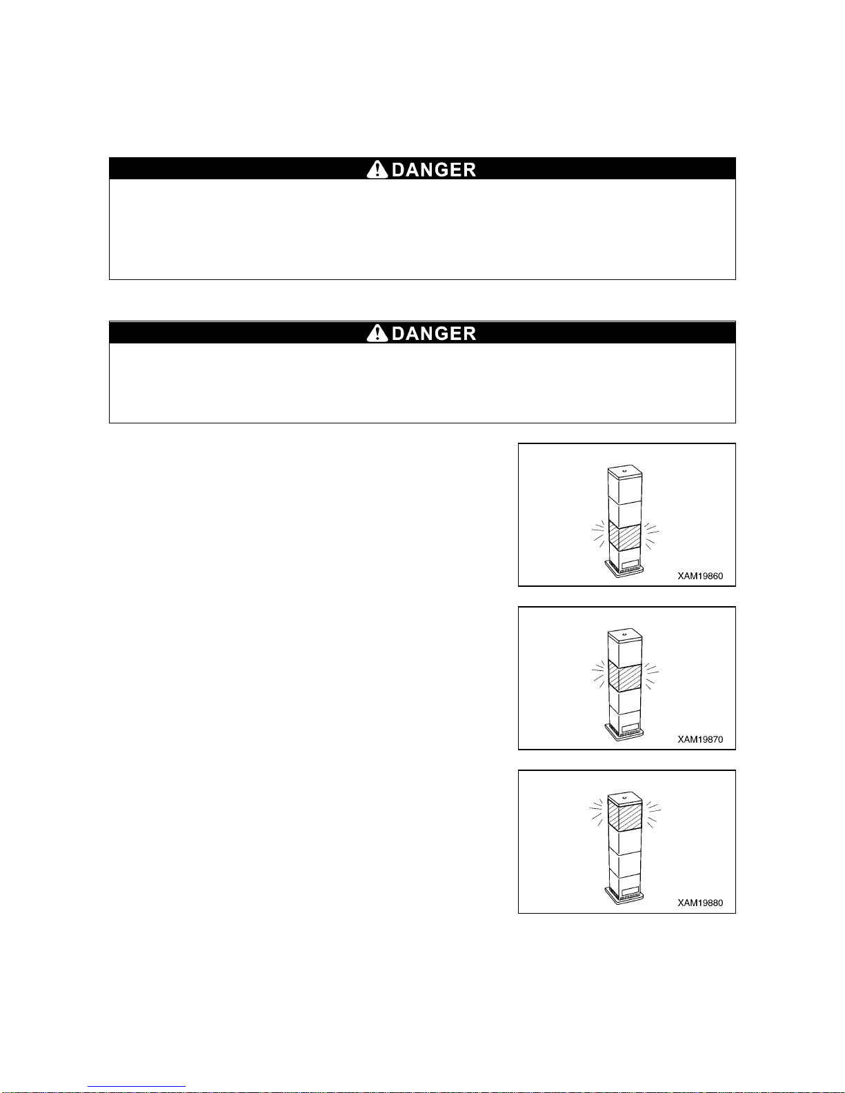
3-20
1.6.3 MOMENT LIMITER OPERATIONS
The moment limiter is a device for unexpected events. Operations relying on the device will rather incur
danger.
Pay sufficient attentio n during the operation not to cause auto-stop of the crane.
[1] PROHIBITED ACTIONS AFTER AUTO STOP
The following crane operations are prohibited after the crane has stopped automatically due to
overloading. These operations may cause overturning of the machine or breakage of th e boom
and are very dangerous.
• Boom lowering operation • Boom raising operation • Boom extending operation
• Hook raising operation • Crane slewing operation
[2] RECOVERY OPERATION AFTER AUTO STOP
Be sure to switch the engi ne speed to low speed and p erform crane operation ca refully if the
moment limiter load factor is 90 % or higher.
Performing crane operation at high engine speed will swing the hoisted load and is very
dangerous, causing overloading and it may break the boom.
1. With load factor of “less than 90 %”
When the hoisting load is less than 90 % of the rated total load, the
working status lamp lights in green, indicating normal operation
status.
2. With load factor of “90 to less than 100 %”
When the hoisting load reaches 90 % of the rated total load
(pre-warning), the working status lamp changes from green to
yellow and the alarm sounds intermittently, notifying the operator
and those around that the hoisting load is close to the rated total
load.
3. With load factor of “100 % or higher”
When the hoisting load reaches 100 % of the rated total load by
continuing the crane operation after exceeding 90 % of the rated
total load (pre-warning), the working status lamp changes from
yellow to red and the alarm now sounds continuously. The
following crane operations will stop automatically.
• Hook raising operation • Boom extending operation
• Boom lowering operation • Boom raising operation
The audible message of “Peep, overloading” will be issued. Furthermore, the LED of “100 %” on the
moment limiter load factor display lights up.
Page 87
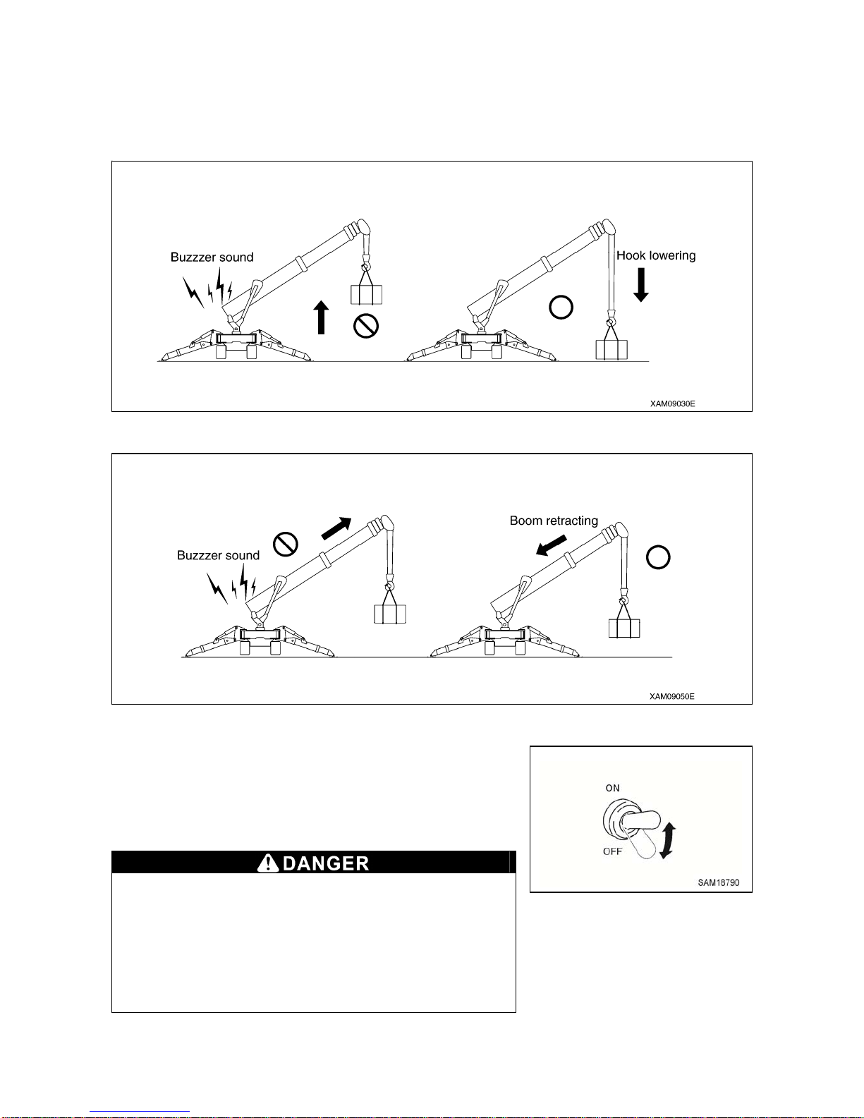
3-21
4. Recovery Operation from Auto Stop
The recovery operation from overloading should be the reverse operation of the crane operation that
caused the auto stop. Perform one of the followings.
(1) Lower the hook and put down the hoisted load on the ground.
(2) Retract the boom.
5.When recovering by boom raising operation
In the case of an automatic stop, when raising of the boom is
unavoidable, the boom raising operation is possible only while
keeping the boom lift bypass switch in the “ON” position.
To return to the “OFF” position, also return the boom raising lever.
Only use this switch when an automatic stop has occurred
through entry into the overload region while lowering or
extending the boom.
Do not use under normal conditions or when lifting clear
from the ground.
If you use this switch when lifting from the ground, there is
a risk of serious accidents such as the machine being
damaged or overturning.
Page 88
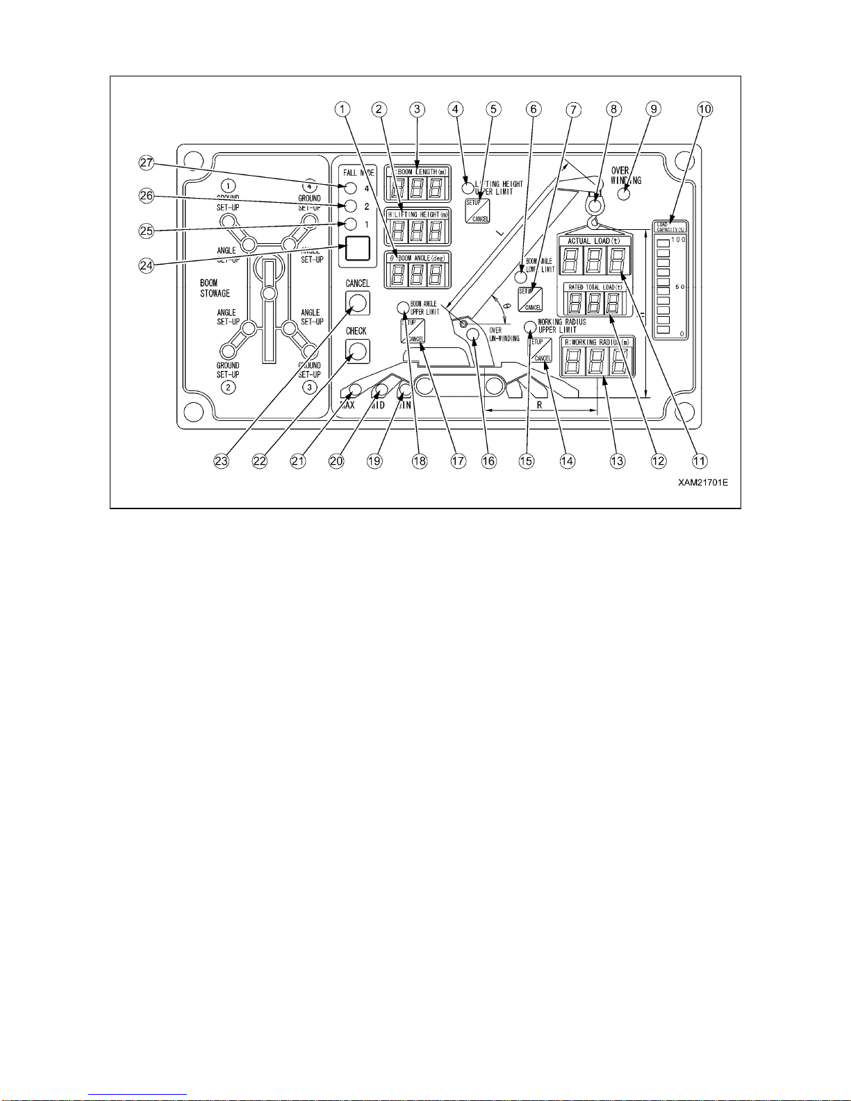
3-22
1.6.4 NAMES OF MOMENT LIMITER DISPLAY UNIT
(1) Boom angle display
(2) Lifting height display
(3) Boom length display
(4) Boom lifting height upper limit LED
(Orange)
(5) Boom lifting height upper limit switch
(6) Boom angle lower limit LED (Orange)
(7) Boom angle lower limit switch
(8) Load factor LED
(Changes to green, yellow, and red)
(9) Over hoist detection LED (Red)
(10) Load capacity display (Yellow)
(11) Actual load display
(12) Rated total load display
(13) Working radius display
(14) Working radius upper limit switch
(15) Working radius upper limit LED (Orange)
(16) Over un-winding LED (Orange)
(17) Boom angle upper limit switch
(18) Boom angle upper limit LED (Orange)
(19) Outrigger MIN. extension LED (Blue)
(20) Outrigger MID. extension LED (Blue)
(21) Outrigger MAX. extension LED (Blue)
(22) Check switch
(23) Cancel switch
(24) Fall mode selector switch
(25) 1-fall fall LED (Blue)
(26) 2-falls fall LED (Blue)
(27) 4-falls fall LED (Blue)
Page 89
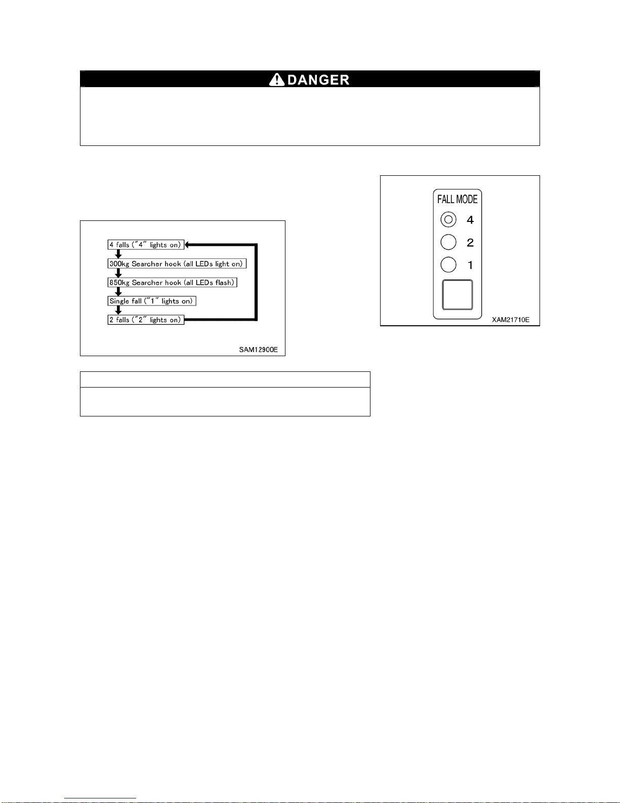
3-23
[1] DESCRIPTIONS OF SWITCHES ON MOMENT LIMITER DISPLAY UNIT
1. WIRE FALLS SELECTOR SWITCH AND WIRE FALLS DISPLAY LED (BLUE)
When entering the number of wire falls, verify the actually used number of wire falls and make
sure to set up correctly.
Entering incorrect number of wire falls may prevent issuance of the pre-warnings and boom
auto-stop even when the overload is near happening, and thus may result in crane damage or
machine trip that may result in serious accidents.
Use this switch to change the number of wire falls.
Keep pressing the switch for 2 seconds or more.
Operation mode of wire falls will change as shown below by
pressing the switch for 2 seconds or more each time.
NOTES
When changing the setting right after doing so, release your
hand from the switch, and then press the switch again.
Page 90
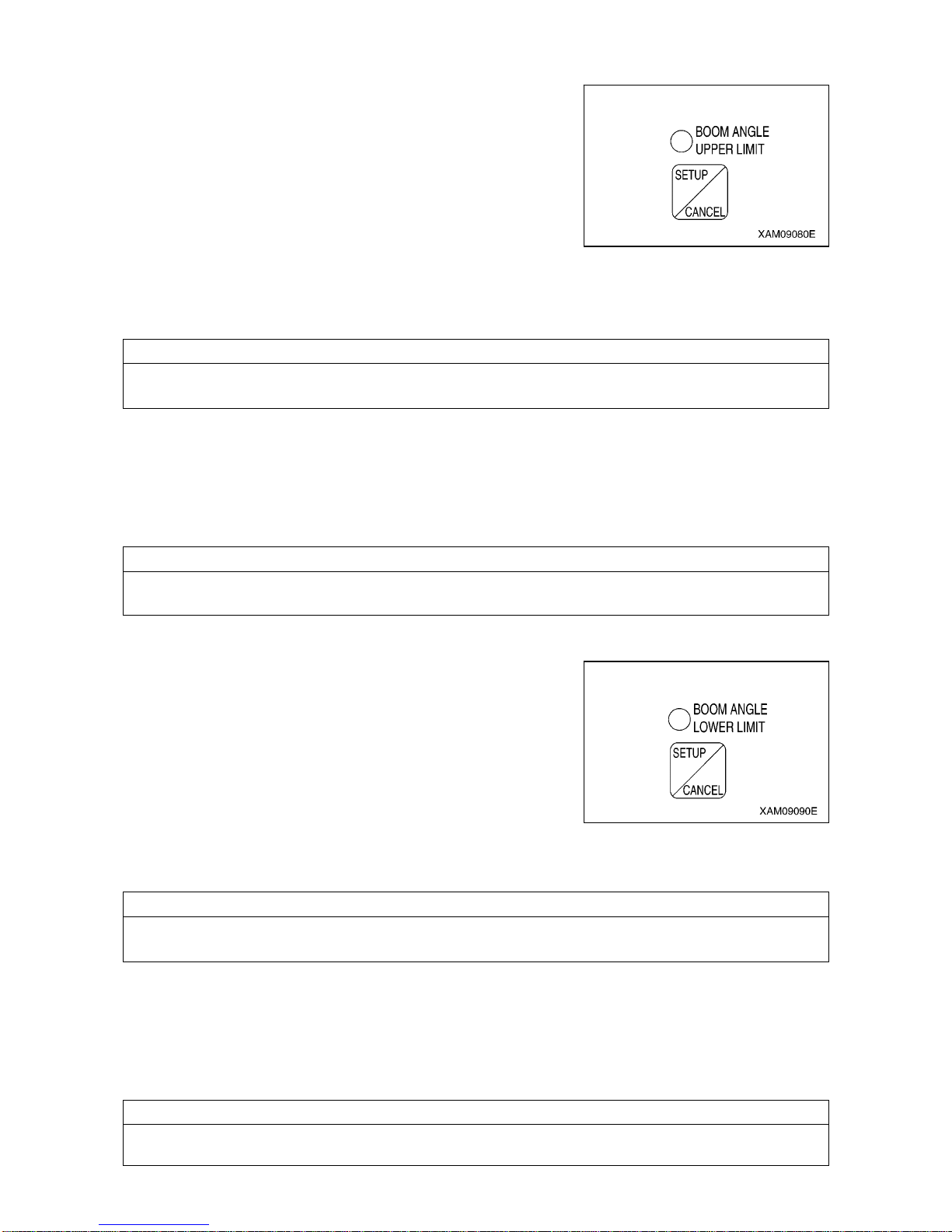
3-24
2. BOOM ANGLE UPPER LIMIT SWITCH AND LED (ORANGE)
Use this switch to set or cancel the boom angle upper limit.
[SETUP]
With no upper limit value being set, set the boom to the angle you
would like, and press the switch for 2 seconds.
The boom angle at this point is set as the upper limit.
At the same time, the LED lights up indicating that the upper limit
value was set.
To enable this setting, turn the key switch to the “ON” position
again after turning it to the “OFF” position, or lower the boom by
“10 degrees” or more from the set boom angle to get out of the
pre-warning zone while the engine is being started.
NOTES
Be sure to verify that the boom automatically stops at the set angle before performing the actual
operation. If the boom does not stop automatically, re-set the boom angle using the procedure above.
When the boom reaches the pre-warning zone or stops at the upper limit with the boom angle upper limit
set, the boom angle upper limit LED flashes.
[CANCEL]
With the upper limit value being set (LED ON), press the switch for 5 seconds.
The current upper limit value setting will be cleared. At the same time, the LED goes off indicating tha t the
upper limit value setting is cleared.
NOTES
The setting and canceling will not repeat even if you keep the switch pressed for more than 2 seconds.
Let your hand go off the switch and press the switch again.
3. BOOM ANGLE LOWER LIMIT SWITCH AND LED (ORANGE)
Use this switch to set or cancel the boom angle lower limit.
[SETUP]
With no lower limit value being set, set the boom to the angle you
would like, and press the switch for 2 seconds.
The boom angle at this point is set as the lower limit.
At the same time, the LED lights up indicating that the lower limit
value was set.
To enable this setting, turn the key switch to the “ON” position again after turning it to the “OFF” position,
or raise the boom by “7 degrees” or more from the set boom angle to get out o f the pre-warning zone while
the engine is being started.
NOTES
Be sure to verify that the boom automatically stops at the set angle before performing the actual
operation. If the boom does not stop automatically, re-set the boom angle using the procedure above.
When the boom reaches the pre-warning zone or stops at the lower limit with the boom angle lower limit
set, the boom angle lower limit LED flashes.
[CANCEL]
With the lower limit value being set (LED ON), press the switch for 5 seconds.
The current lower limit value setting will be cleared. At the same time, the LED goe s off indica ting that th e
lower limit value setting is cleared.
NOTES
The setting and canceling will not repeat even if you keep the switch pressed for more than 2 seconds.
Let your hand go off the switch and press the switch again.
Page 91
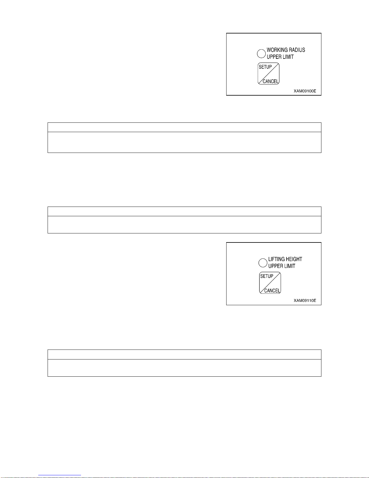
3-25
4. WORKING RADIUS UPPER LIMIT SWITCH AND LED (ORANGE)
Use this switch to set or cancel the working radius upper limit.
[SETUP]
With no upper limit value being set, set the boom to the working
radius you would like, and press the switch for 2 seconds.
The working radius at this point is set as the upper limit.
At the same time, the LED lights up indicating that the upper limit
value was set.
To enable this setting, turn the key switch to the “ON” position again after turning it to the “OFF” position,
or reduce the working radius by “1.3 m” or more from the set working radius to get out of the pre-warning
zone while the engine is being started.
NOTES
Be sure to verify that the boom automatically stops at the set working radius before performing the
actual operation. If the boom does not stop auto matically, re-set the wo rking radius u sing the procedur e
above.
When the boom reaches the pre-warning zone or stops at the upper limit with the working radius upper
limit set, the working radius upper limit LED flashes.
[CANCEL]
With the upper limit value being set (LED ON), press the switch for 5 seconds.
The current upper limit value setting will be cleared. At the same time, the LED goes off indicating tha t the
upper limit value setting is cleared.
NOTES
The setting and canceling will not repeat even if you keep the switch pressed for more than 2 seconds.
Let your hand go off the switch and press the switch again.
5. LIFTING HEIGHT UPPER LIMIT SWITCH AND LED (ORANGE)
Use this switch to set or cancel the lifting height upper limit.
While the lifting height is restricted by detecting the height of the tip
of the boom, the lifting height on the display panel shows the lifting
height when the hook was raised to the over hoist detection status.
[SETUP]
With no upper limit value being set, set the boom to the lifting
height you would like, and press the switch for 2 seconds.
The lifting height at this point is set as the upper limit.
At the same time, the LED lights up indicating that the upper limit value was set.
To enable this setting, turn the key switch to the “ON” position again after turning it to the “OFF” positio n, or
reduce the lifting height by “1.3 m” or more from the set lifting height to get out of the pre-warning zone
while the engine is being started.
NOTES
Be sure to verify that the boom automatically stops at the set lifting height before performing the actual
operation. If the boom does not stop automatically, re-set the lifting height using the procedure above.
When the boom reaches the pre-warning zone or stops at the upper limit with the lifting height upper limit
set, the lifting height upper limit LED flashes.
Page 92
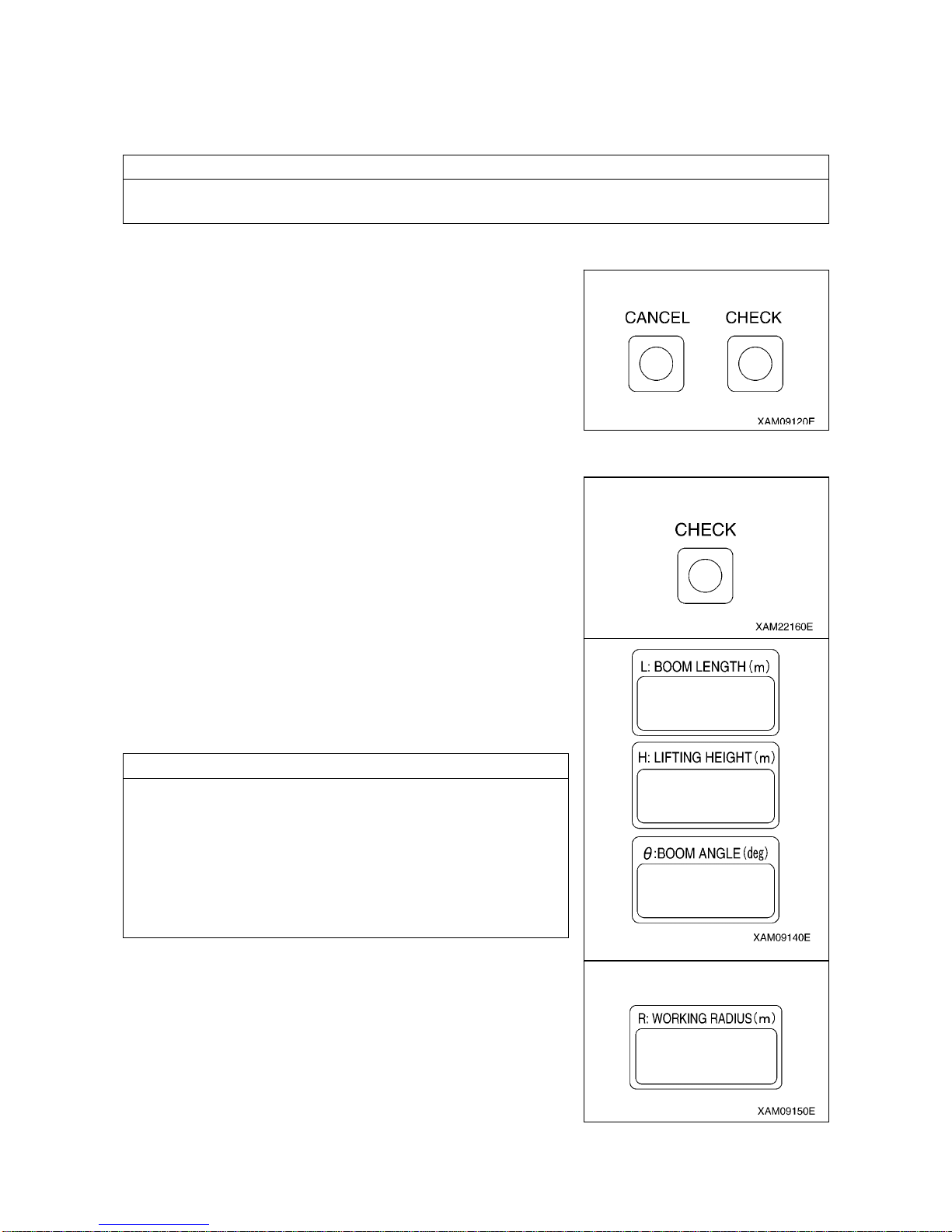
3-26
[CANCEL]
With the upper limit value being set (LED ON), press the switch for 5 seconds.
The current upper limit value setting will be cleared. At the same time, the LED goes off indicating tha t the
upper limit value setting is cleared.
NOTES
The setting and canceling will not repeat even if you keep the switch pressed for more than 2 seconds.
Let your hand go off the switch and press the switch again.
6. CANCEL SWITCH
Use this switch to ca ncel the all setti ng sets in the section 2 to 5
above.
• Press this switch and “CHECK” switch at the same time for 5
seconds or more.
The all value sets in the section 2 to 5 above will be canceled.
7. CHECK SWITCH
Use this switch to verify the values set in the section 2 to 5 above.
• Press this switch. Every time the switch is pressed, the set value
will be displayed in the following order.
(1) “Boom angle upper limit value” is displayed at the boom
angle display section.
(2) “Boom angle lower limit value” is displayed a t the boom angle
display section.
(3) “Working radius upper limit value” is displayed at the working
radius display section.
(4) “Lifting height upper limit value” is displayed at the lifting
height display section.
(5) Returns to the original display.
NOTES
• When a set value is displayed, th e LED for its setting switch
section flashes at the same time.
• If no switch was pressed for 5 seconds or another switch was
pressed with a set value being displayed, the display goes back
to the original display.
• The display will be a blank for the item to which no value is set.
• The display sections other than for th e corresponding items will
be blank.
Page 93
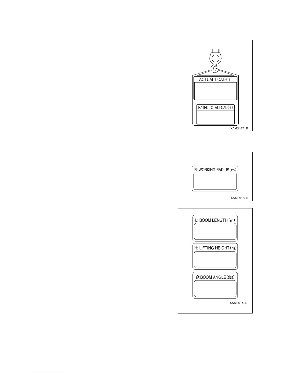
3-27
[2] DESCRIPTIONS OF MOMENT LIMITER DISPLAY UNIT
For LEDs not described in this section, see “Operation 1.6.4 Names of moment limiter display unit”.
1. ACTUAL LOAD DISPLAY SECTION
This section constantly displays the actual load of the hoisted load
during the crane operation.
The actual load indicates the total weight of the hoisted load
including rigging and the hook block.
If “0.0” to “0.1” is displayed when nothing is being hoisted, the
system is normal.
If the value displayed is out of this range, contact us or our sales
service agency.
2. RATED TOTAL LOAD DISPLAY SECTION
This section displays the number of wire falls on the hoo k, working
radius, currently hoistable rated total load (hook weight + rigging
weight + load to be hoi sted) computed o ut of the conditi ons such
as the degree of outrigger extension.
3. WORKING RADIUS DISPLAY SECTION
This section constantly displays the current working radius during
the crane operation.
The working radius is the horizontal distance from the crane
slewing center to the center of the hook.
4. BOOM LENGTH DISPLAY SECTION
This section constantly displays the current boom length during the
crane operation.
The boom length is the distance from the boom foot pin to the
sheave pin at the end of the boom.
5. LIFTING HEIGHT DISPLAY SECTION
This section constantly displays the current lifting height dur ing the
crane operation.
The lifting height is the vertical distance from the ground to the
bottom of the hook.
6. BOOM ANGLE DISPLAY SECTION
This section constantly displays the current boom angle d uring the
crane operation.
The boom angle is the angle the boom and the horizontal line form.
Page 94
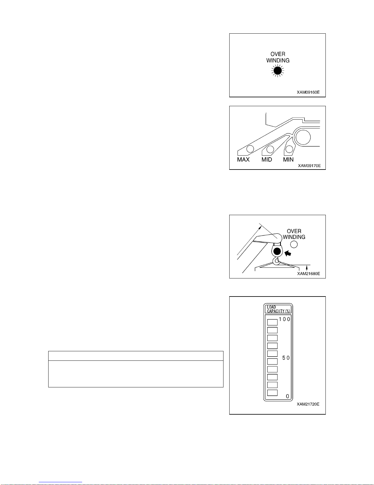
3-28
7. OVER WINDING LED (RED)
This LED flashes up when the hook is overwound, and issues
overwinding warning and causes an automatic stop.
This LED also flashes when the hook is stowed during the hook
stowing operation. This is normal.
8. OUTRIGGER EXTENSION LED (BLUE)
The LED lights up to indicate the outrigger extension status.
• If any of the four outriggers has not properly reached the middle
extension position, the “MIN” LED lights up.
• If all the four outriggers properly reach the middle extension
position, the “MID” LED lights up.
• If all the four outriggers reach the maximum extension position,
the “MAX” LED lights up.
Even if you thought you had set the outriggers at the maximum
extension position, the “MID” LED lights up if any of the outriggers
did not properly reach the maximum extension position.
9. LOAD FACTOR LED (CHANGES TO GREEN/YELLOW/RED)
This LED indicates the status of the moment limiter load factor by
its illumination.
• The LED lights up in green if the load factor is less than 90 %.
• The LED lights up in yellow if the load factor is 90 to less than
100 %.
• The LED lights up in red if the load factor is 100 % or higher.
10. LOAD FACTOR DISPLAY (YELLOW)
This display indicates the status of the moment limiter l oad factor
by its illumination.
• The load factor is indicated by ON/OFF of the “bar” according to
the changes of the load factor.
• All the “bars” will be ON when the load factor reaches 100 % or
higher.
NOTES
When the load factor is about 50 %, all the “bars” around the
number “50” on the right and below are ON.
All the “bars” around the number “50” and above are OFF.
Page 95
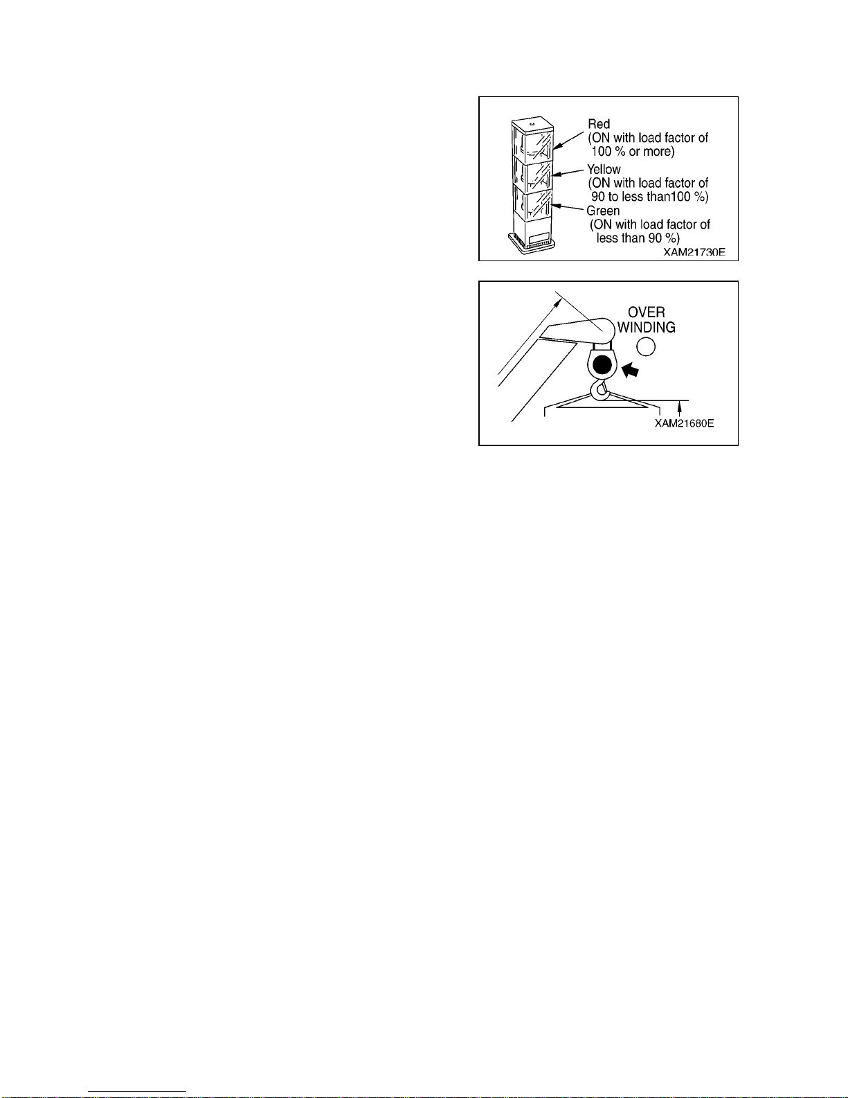
3-29
1.6.5 MOMENT LIMITER FUNCTIONS
[1] OVERLOAD WARNING
1. SAFETY ZONE (“Actual load” is less than 90 % of the
“rated total load”)
• Green of the working status lamp lights up.
• The LED lights up in green if the load factor is less than
90 %.
2. PRE-WARNING (“Actual load” is 90 to less than 100 % o f
the “rated total load”)
• Yellow of the working status lamp lights up.
• The LED lights up in yellow if the load factor is 90 to less
than 100 %.
• The alarm bleeps intermittently.
3. LIMIT WARNING (“Actual load” is 100 % or higher than
the “rated total load”)
• Red of the working status lamp lights up.
• The LED lights up in red if the load factor is 100 % or
higher.
• The alarm bleeps continuously.
• The hazardous operation of the boom stops
automatically.
• Voice message of “Overloading” is heard.
• “Load factor 100 % or more” LED (yellow) lights up.
4. CLEARING LIMIT WARNING AUTO STOP
If the system stops automatically, promptly perfo rm the recovery operation caused by overloading.
See “Operation 1.6.3 [2] Recovery Operation After Auto Stop” for recovery operations.
Page 96
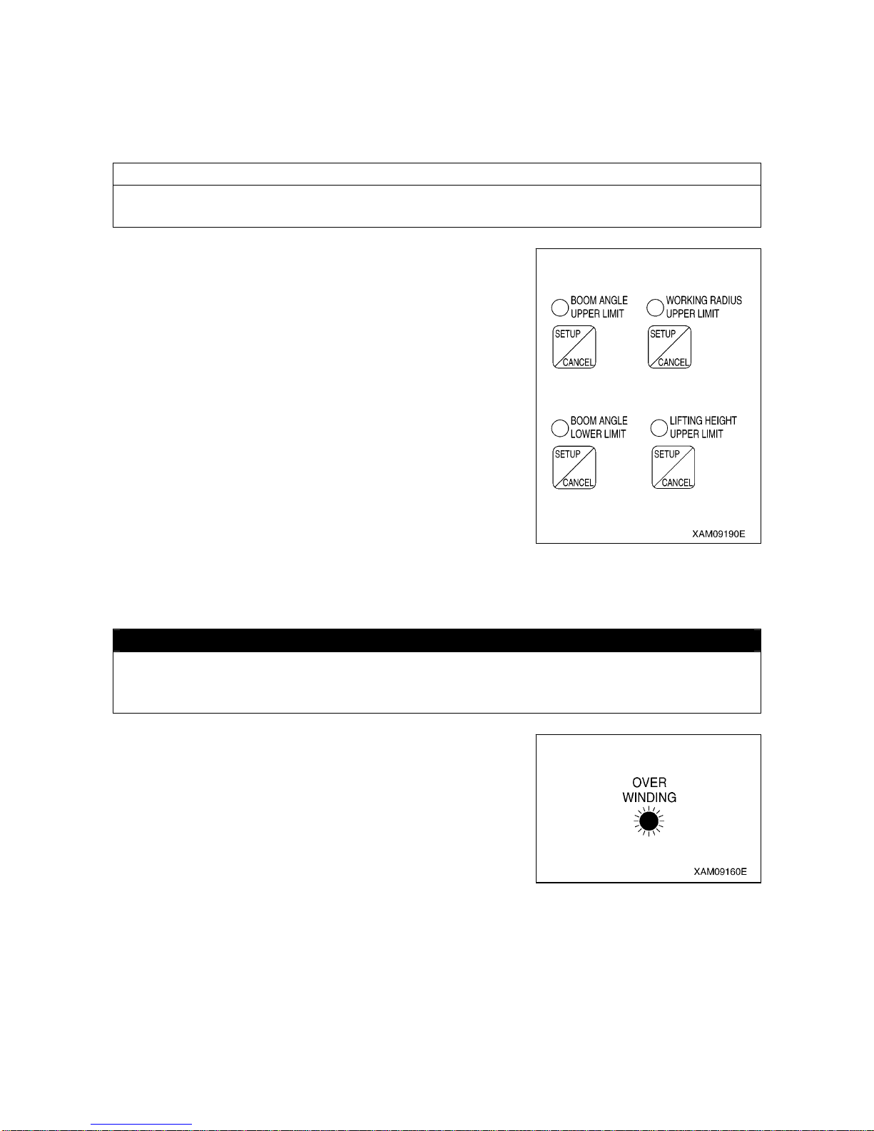
3-30
[2] WORKING ENVELOPE RESTRICTION WARNING
When the working envelope gets close to the set restriction value, a warning is issued to notify the
operator and people around of the situation.
The last status of the set value for the working envelope restriction is memorized even if the starter switch
is turned to the OFF position.
NOTES
See “Operation 1.6.4 [1] Descriptions of Switches on Moment Limiter Display Unit” for how to set the
value for working envelope restriction.
When the working envelope has been set, the restr iction will be as
follows.
1. SAFETY ZONE
• The appropriate working envelope restriction LED (orange)
lights up.
• Green of the working status lamp lights up.
2. PRE-WARNING
• The appropriate working envelope restriction LED (orange)
lights up.
• The alarm bleeps intermittently.
3. LIMIT WARNING
• The appropriate working envelope restriction LED (orange)
lights up.
• Red of the working status lamp lights up.
• The alarm bleeps continuously.
• The hazardous operation of the boom stops automatically.
[3] OVER HOIST DETECTOR
CAUTION
Pay attention to the distance between the hook and boom when raising the hook.
Extending the boom also raises the hook.
Always check the hook height when extending the boom.
When you overwind the hook when raising the hook or extending
the boom,
• The “Overwinding” LED (red) flashes.
• The alarm bleeps continuously.
• The hook raising and boom extending operation stop
automatically.
• The voice saying “hook is overwinded” is heard.
In case of auto stop, immediately perform the recovery operation.
Perform hook lowering and boom retracting operations as r ecovery
operations.
Page 97
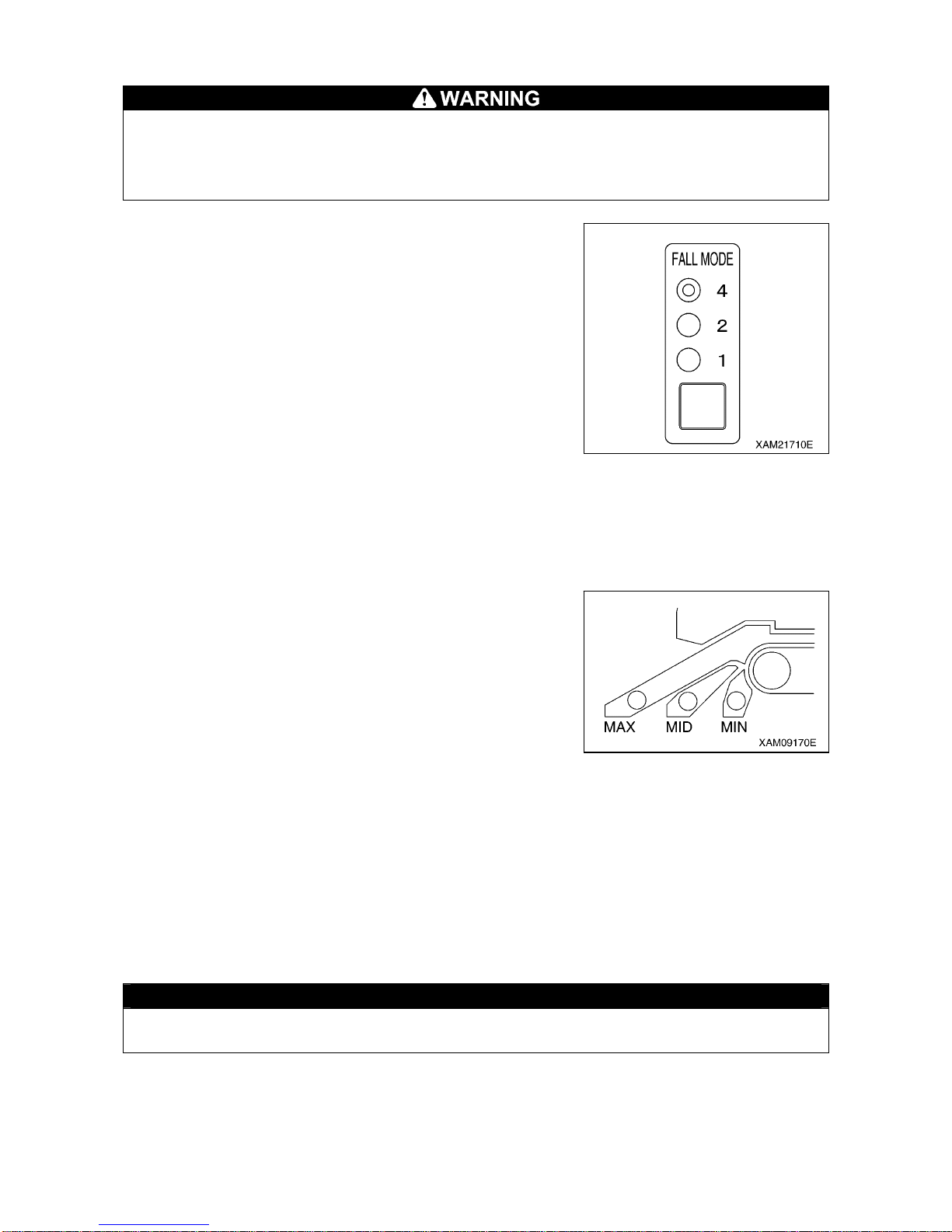
3-31
[4] NUMBER OF WIRES SELECTOR SWITCH
• Stop the crane operation when changing the number of wires hooked using the number of
wires selector switch.
Changing the number of wires during the crane operation can cause unexpected accidents.
• Perform the crane operation always after matching the number of wires display on the moment
limiter and the actual number of wires. Mistaking the number of wires c ause serious ac cidents.
The wire rope has the safe load per rope determined.
Determine the number of wires according to the maximum load to
be hoisted.
The actual number of wires hooked and the number of wires
display on the moment limiter must match.
With this machine, the hook for four/two wire ropes is referred to as
the standard specifications.
The last status of the set number of wires is memorized even if the
starter switch is turned to the OFF position.
[5] BOOM UPPER LIMIT DETECTION
When the boom is raised and the boom angle reaches “about 77
degrees”, the boom raising operation stops automatically.
[6] BOOM LOWER LIMIT DETECTION
When the boom is lowered and the boom angle reaches “about 3
degrees”, the boom lowering operation stops automatically.
[7] OUTRIGGER EXTENSION DETECTION
The outrigger extension status is detected with the limit switch
mounted to each of four outriggers, lighting the appropriate LED
(blue) of the “MIN”, “MID”, or “MAX” and changing the rated total
load.
1.6.6 MOMENT LIMITER STARTING STATUS
The moment limiter checks its function for 2 seconds when the starter switch is turned to the ON position.
Meanwhile,
• The red of the working status lamp lights up.
• All the LEDs light up.
• The horn sounds momentarily.
Then, if the moment limiter and the sensors are normal upon the co mpletion of the fun ctional check of the
moment limiter, the red of the working status lamp goes off and gr een of the working status lamp lights u p
indicating that the machine is ready for use.
CAUTION
If the red of the working status lamp does not go off after completing the functional check of the
moment limiter, be sure to contact us or our sales service agency.
Page 98
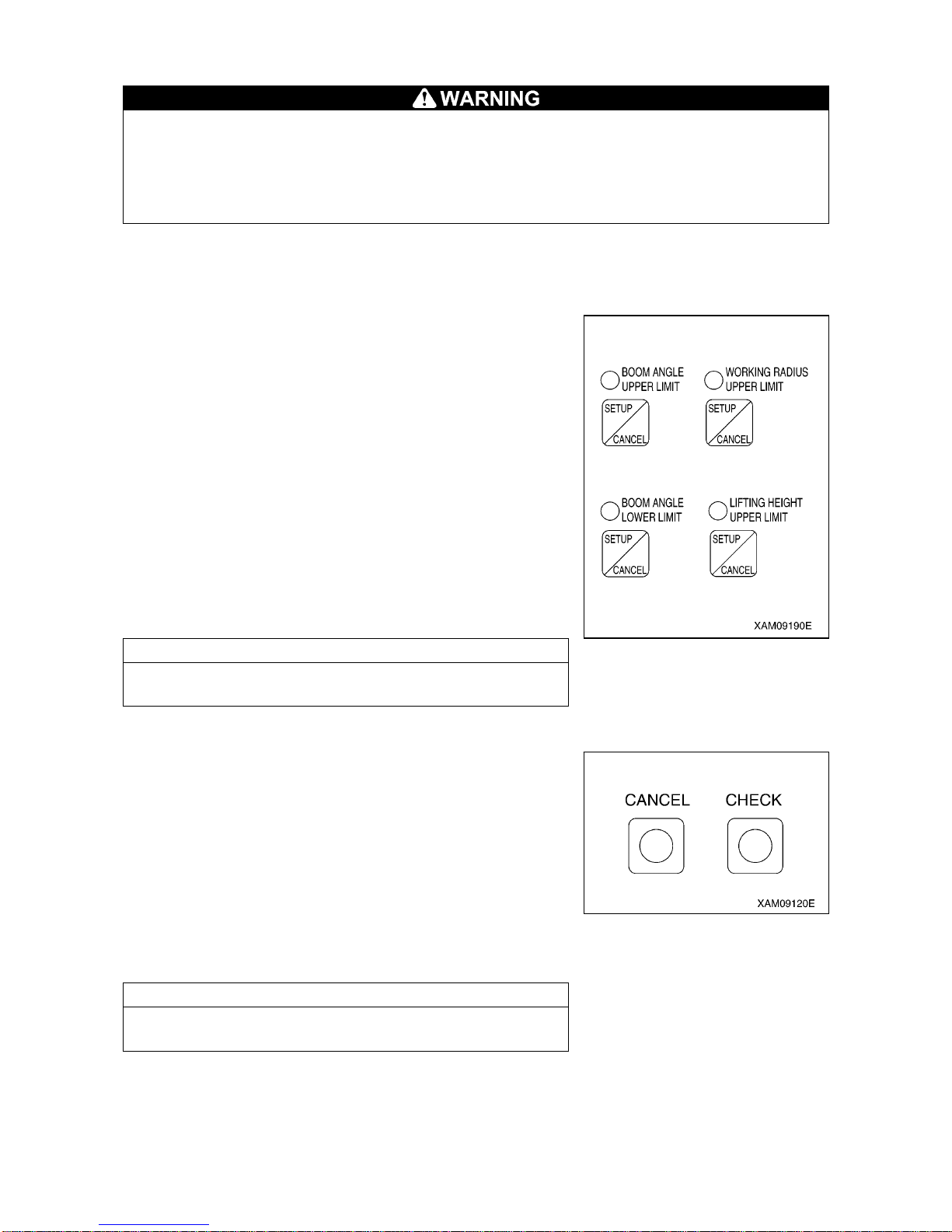
3-32
1.6.7 MOMENT LIMITER WORKING ENVELOPE SETTING
• The boom may go beyond the set value when operated at high speed even if the working
envelope was restricted by the moment limiter.
Be sure to set the working envelope with safe distance from obstacles.
Operate the crane at low speed.
• Be sure to verify that the boom stops at the set position after setting the boom working
envelope.
If the boom working envelope is limited due to working space issue, you can set the boom working
envelope to the desired value.
[1] SETTING WORKING ENVELOPE
Operate the boom to the limit of the working envelope you would
like to restrict, and press the appropriate SETUP/CANCEL switch
for 2 seconds.
You can set that limit value.
At the same time, the LED above the appropriate switch lights up.
Then, return the boom to the following setting to enable the
restriction control.
“Set value – 10 degrees or more” for boom upper limit.
“Set value + 7 degrees or more” for boom lower limit.
“Set value – 1.3 m or less” for working radius upper limit
“Set value – 1.3 m or less” for lifting height (With [Lower] or
[Retract] operation of the boom)
Or, turn the starter switch to the “OFF” position and then turn again
to the ”ON” position to enable the restriction.
NOTES
The last status of the set value has been held in memory even if
the starter switch is turned to the “OFF” position.
[2] CANCELING WORKING ENVELOPE SETTING
• Press and hold the CANCEL switch and CHECK switch at the
same time for 5 seconds or more.
All the set working envelope restrictions are canceled.
At the same time, the LED above all the working envelope limit
switches go off to complete the cancellation of the settings.
• Press the SETUP/CA NCEL switch of the item whic h restriction
you would like to cancel for 5 seconds.
The set value of only the item can be canceled.
At the same time, the LED above the switch goes off to complete
the cancellation of the setting.
NOTES
See “Operation 1.6.4 [1] Descriptions of Switches on Moment
Limiter Display Unit” for how to set limit on the working envelope.
Page 99
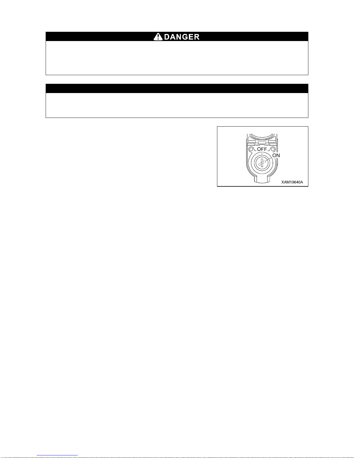
3-33
1.6.8 EMERGENCY STOP CANCEL SWITCH
Do not turn ON (cancel) the emergency stop cancel switch unless you find an error or
check/perform maintenance on detectors.
When turning ON (cancel) the emergency stop cancel switch, always shift the crane speed to
low. Keep the switch key removed during normal crane operation.
CAUTION
Do not use the emergency stop cancel switch when stowing the hook. The winch wire rope may
be cut, causing the hook to fall or boom to be damaged. Use the hook storw ing switch for
stowing the hook.
Use the emergency stop cancel switch when inspecting,
performing maintenance, and canceling the operation stop as
needed.
Open the cover when using the switch.
• OFF (Auto): Turn the key counterclockwise.
The operation stop functions.
The key can be removed or inserted at this position.
• ON (Cancel): Turn the key clockwise and hold it at that position.
The operation stop function is canceled while the key
is held.
Page 100
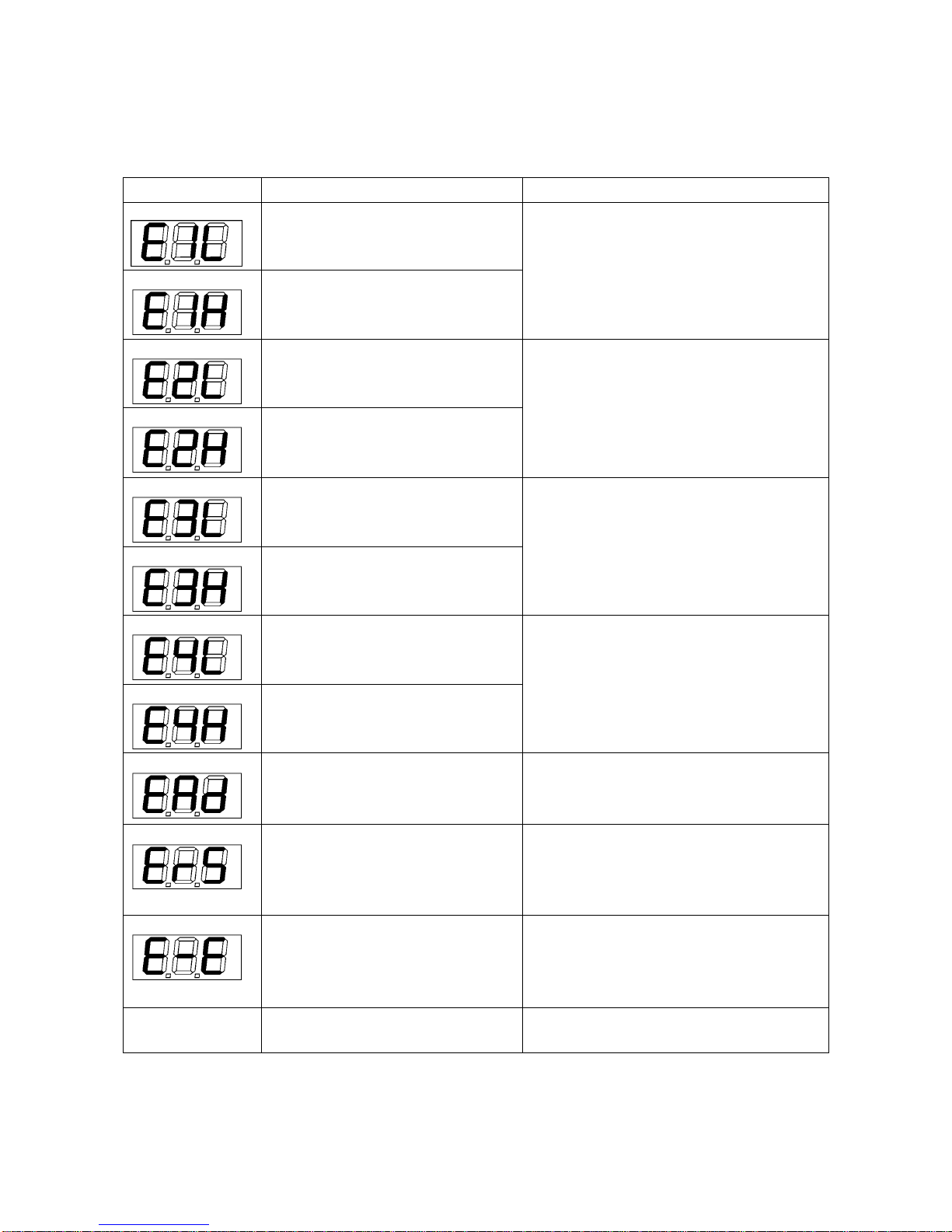
3-34
1.6.9 MOMENT LIMITER ERROR CAUSES AND ACTIONS TO BE TAKEN
The moment limiter displays an error code at the “rated total load” display section on the display panel to
notify the error.
If an error code shown in the table below was displayed, contact us or our sales service agency.
Error Code Error Details Actions to Be Taken
E1L
The input to pressure sensor 1 is
lower than the specified value.
Check the installation of the pressure
sensor 1.
E1H
The input to pressure sensor 1 is
higher than the specified value.
E2L
The input to pressure sensor 2 is
lower than the specified value.
Check the installation of the pressure
sensor 2.
E2H
The input to pressure sensor 2 is
higher than the specified value.
E3L
The input to angle detector is lower
than the specified value.
Check the installation of the angle detector.
E3H
The input to angle detector is higher
than the specified value.
E4L
The input to length detector is lower
than the specified value.
Check the installation of the length
detector.
E4H
The input to length detector is higher
than the specified value.
EAD
The AD converter at the converter
section is not functioning properly.
Turn the starter switch to the “OFF” position
and then to the “ON” position again. If an
error is displayed again, change the
converter.
ERS
The communication between the
converter section and the display
unit is not carried out properly.
• Check the cable between the display unit
and the converter. If the cable is normal,
change the converter.
• Check the fuse built-in the converter.
E-E
Error with calibration memory.
This error is also issued when
calibration has not been done yet.
Turn the starter switch to the “OFF” position
and then to the “ON” position again. If an
error is displayed again, change the display
unit.
No displayed
--- Check the fuse built-in the display unit.
 Loading...