


101E-OM0906-00
OPERATION MANUAL
MINI-CRAWLER CRANE
Serial No. G0121 and up
k WARNING
Unsafe use of this machine may cause serious injury or death. Operators
must read this manual before operating this machine. This manual should
be kept near the machine for reference and periodically reviewed by all
personnel who will come into contact with it.
NOTICE
MAEDA has Operation Manual written in some other languages. If a foreign
language manual is necessary, contact your local distributor for availability.


0-1
CONTENTS
ITEM
Page
INTRODUCTION
1- 1
1. INTRODUCTION
1- 2
2.FOR SAFE USE OF MACHINE
1- 3
3. MACHINE OVERVIEW
1- 4
3.1 SPECIFIED OPERATIONS
1- 4
3.2 MACHINE CONFIGURATION
1- 4
3.3 MACHINE FUNCTIONS
1- 5
4. QUALIFICATION FOR OPERATION
1- 6
4.1 QUALIFICATION FOR CRANE OPERATION
1- 6
5. TERMINOLOGY
1- 7
5.1 DEFINITION OF TERMS
1- 7
5.2 DIAGRAM OF WORKING RADIUS AND LIFTING HEIGHT
1- 8
5.3 TOTAL RATED LOAD CHART
1- 9
5.4 ANGLE INDICATOR
1-14
SAFETY
2- 1
1. BASIC PRECAUTIONS
2- 2
2. DRIVING RELATED PRECAUTIONS
2- 7
2.1 BEFORE STARTING THE ENGINE
2- 7
2.2 AFTER STARTING THE ENGINE
2- 8
2.3 WORKING WITH THE CRANE
2-12
3. TRANSPORT PRECAUTIONS
2-21
4. BATTERY HANDLING PRECAUTIONS
2-23
5. MAINTENANCE PRECAUTIONS
2-25
5.1 PRECAUTIONS BEFORE MAINTENANCE
2-25
5.2 PRECAUTIONS DURING MAINTENANCE
2-27
6. SAFETY LABEL LOCATIONS
2-32
7. WEEE DIRECTIVE LABEL LOCATIONS
2-39
OPERATION
3- 1
1. MACHINE BY SECTION
3- 2
1.1 MACHINE BY UNIT
3- 2
1.2 TRAVELLING OPERATION UNIT
3- 3
1.2.1 DESCRIPTION OF EACH LEVER
3- 4
1.2.2 DESCRIPTION OF EACH SWITCH
3- 6
1.2.3 DESCRIPTION OF EACH METER AND LAMP
3- 8
1.3 CRANE OPERATION UNITS
3- 9
1.3.1 DESCRIPTION OF EACH LEVER
3-10
1.3.2 DESCRIPTION OF EACH SWITCH
3-11
1.4 MOMENT LIMITER (OVERLOAD DETECTOR)
3-16
1.4.1 MOMENT LIMITER CONFIGURATION
3-16
1.4.2 FUNCTION OF MOMENT LIMITER
3-17
1.4.3 MOMENT LIMITER OPERATIONS
3-18

0-2
ITEM
Page
1.4.4 NAMES OF MOMENT LIMITER DISPLAY UNIT
3-20
1.4.5 OTHER MOMENT LIMITER FUNCTIONS
3-29
1.4.6 MOMENT LIMITER STARTING STATUS
3-30
1.4.7 MOMENT LIMITER ERROR CAUSES AND ACTIONS TO BE TAKEN
3-31
1.5 OVER HOIST DETECTOR
3-32
1.6 MACHINERY COVER
3-33
2. OPERATIONS
3-34
2.1 CHECKS BEFORE OPERATION
3-34
2.1.1 CHECKS BEFORE STARTING THE ENGINE (VISIBLE CHECKS)
3-34
2.1.2 CHECKS BEFORE STARTING THE ENGINE
3-37
2.1.3 CHECKS AFTER STARTING THE ENGINE
3-46
2.2 STARTING THE ENGINE
3-54
2.2.1 NORMAL ENGINE START
3-54
2.2.2 STARTING THE ENGINE WITH AUXILIARY STARTER SWITCH
3-56
2.2.3 STARTING THE ENGINE WITH RECOIL STARTER
3-58
2.3 OPERATIONS AND CHECKS AFTER STARTING THE ENGINE
3-59
2.4 BREAKING-IN MACHINE
3-61
2.5 MACHINE TRAVELLING POSITION
3-61
2.6 STARTING MOVING THE MACHINE
3-62
2.7 CHANGING MACHINE TRAVELLING MODE
3-63
2.8 CHANGING DIRECTION OF THE MACHINE
3-63
2.9 STOPPING/PARKING THE MACHINE
3-64
2.10 STOPPING THE ENGINE
3-65
2.11 INSPECTION AFTER STOPPING THE ENGINE
3-65
2.12 CAUTIONS WHILE DRIVING
3-66
2.13 OUTRIGGER SET UP OPERATION
3-68
2.13.1 NAME OF OUTRIGGER COMPONENTS
3-70
2.13.2 OUTRIGGER SET UP OPERATION
3-70
2.14 CAUTIONS BEFORE CRANE OPERATION
3-75
2.15 OPERATIONS BEFORE CRANE OPERATIONS
3-76
2.16 CRANE OPERATION POSITION
3-77
2.17 HOOK RAISING/LOWERING OPERATION
3-78
2.18 BOOM DERRICKING OPERATION
3-79
2.19 BOOM TELESCOPING OPERATION
3-80
2.20 SLEWING OPERATION
3-81
2.21 ACCELERATION OPERATION
3-82
2.22 CRANE STOWING OPERATION
3-83
2.23 OUTRIGGER STOWING OPERATION
3-85
2.24 DO’S AND DON’TS DURING CRANE OPERATIONS
3-91
3. HANDLING RUBBER TRACKS
3-93
3.1 GOOD USE
3-93
3.2 WARRANTY
3-93
3.3 PROHIBITIONS AND CAUTIONS WHEN USING RUBBER TRACKS
3-94
4. WHAT TO DO WITH TWISTED WINCH WIRE ROPE
3-97

0-3
ITEM
Page
5. TRANSPORTATION
3-98
5.1 LOADING/UNLOADING
3-98
5.2 HOISTING MACHINE
3-99
5.3 CAUTIONS IN LOADING MACHINE
3-100
5.4 CAUTIONS DURING TRANSPORTATION
3-100
6. HANDLING IN COLD WEATHER
3-101
6.1 PREPARING FOR LOW TEMPERATURE
3-101
7. LONG-TERM STORAGE
3-103
7.1 BEFORE STORING THE MACHINE
3-103
7.2 DURING STORAGE
3-103
7.3 AFTER STORAGE
3-103
8. HANDLING THE BATTERY
3-104
8.1 CAUTIONS IN HANDLING BATTERY
3-104
8.2 REMOVING/INSTALLING THE BATTERY
3-105
8.3 CAUTIONS WHEN CHARGING THE BATTERY
3-106
8.4 STARTING THE ENGINE WITH BOOSTER CABLE
3-107
9. TROUBLESHOOTING
3-109
9.1 ELECTRICAL COMPONENTS
3-109
9.2 MACHINE BODY
3-109
9.3 ENGINE
3-110
INSPECTION AND MAINTENANCE
4- 1
1. PRECAUTIONS FOR MAINTENANCE
4- 2
2. BASIC MAINTENANCE
4- 4
3. LEGAL INSPECTION
4- 6
4. CONSUMABLES
4- 6
5. LUBRICATING OIL
4- 7
5.1 USE OF LUBRICATING OIL ACCORDING TO TEMPERATURES
4- 7
6. ACCESSORY TOOLS AND STANDARD TIGHTENING TORQUE
4- 8
6.1 ACCESSORY TOOLS
4- 8
6.2 STANDARD TIGHTENING TORQUE LIST
4- 8
7. INSPECTION AND MAINTENANCE LIST
4-10
8. MAINTENANCE PROCEDURES
4-12
8.1 INITIAL 10 HOUR MAINTENANCE
4-12
8.2 INITIAL 25 HOUR MAINTENANCE
4-12
8.3 INITIAL 50 HOUR MAINTENANCE
4-12
8.4 INITIAL 200 HOUR MAINTENANCE
4-12
8.5 CHECKS BEFORE OPERATION
4-12
8.6 IRREGULAR MAINTENANCE
4-13
8.7 MAINTENANCE EVERY 50 HOURS
4-24
8.8 MAINTENANCE EVERY 100 HOURS
4-30
8.9 MAINTENANCE EVERY 250 HOURS
4-30
8.10 MAINTENANCE EVERY 500 HOURS
4-31
8.11 MAINTENANCE EVERY 1000 HOURS
4-33

0-4
ITEM
Page
SPECIFICATIONS
5- 1
1. SPECIFICATIONS
5- 2
2. OVERALL DIMENSIONS
5- 4
3. OUTRIGGER SPREAD DIMENSIONS
5- 5
4. RATED TOTAL LOAD CHART
5- 6
5. WORKING RANGE
5- 9
REMOTE CONTROL
6- 1
1. OUTLINE OF REMOTE CONTROLLER
6- 2
1.1 FEATURE
6- 2
1.2 CONFIGURATION
6- 2
1.3 FUNCTIONS OF REMOTE CONTROL SYSTEM
6- 3
2. SAFETY PRECAUTIONS
6- 4
2.1 FOR SAFETY OPERATIONS
6- 4
2.2 PRECAUTIONS FOR CRANE OPERATION
6- 6
2.2.1 PRIOR TO STARTING ENGINE
6- 6
2.2.2 SUBSEQUENT TO STARTING ENGINE
6- 7
2.2.3 TERMINATING THE OPERATION
6- 7
3. LOCATIONS OF SAFETY LABELS
6- 8
4. COMPONENTS OF THE TRANSMITTER
6-10
5. COMPONENTS OF THE RECEIVER
6-15
5.1 COMPONENTS OF THE RECEIVER
6-15
5.2 FUSE IN THE RECEIVER
6-17
6. MODE SETTING OF THE TRANSMITTER
6-18
6.1 A MODE
6-18
6.1.1 OPENING A MODE SCREEN
6-18
6.1.2 MESSAGES IN THE A MODE SCREEN
6-18
6.1.3 AN EXAMPLE FOR SETTING IN THE A MODE
6-22
6.2 PROCEDURE IN THE OPERATION MODE
6-23
6.2.1 CALL OUT CRANE MODE
6-23
6.2.2 CALL OUT OUTRIGGER MODE
6-24
7. CHECKING BEFORE OPERATION
6-26
7.1 CHECKING BEFORE STARTING ENGINE
6-26
7.1.1 CHECKING BEFORE TURNING ON THE TRANSMITTER
6-26
7.1.2 CHECKING AFTER TURNING ON THE TRANSMITTER
6-27
7.1.3 CHECKING RECEIVER
6-31
7.2 CHECKING AFTER STARTING ENGINE
6-32
7.2.1 VERIFICATION FOR THE ENGINE START AND STOP
6-32
7.2.2 CHECKING “OUTRIGGER MODE” OPERATION
6-33
7.2.3 CHECKING “CRANE MODE” OPERATION
6-35
8. OPERATION
6-38
8.1 CAUTIONS BEFORE OPERATION
6-38
8.2 OPERATION IN OUTRIGGER MODE
6-39
8.2.1 OUTRIGGER SETTING
6-41
8.2.2 OUTRIGGER STOWING
6-43

0-5
ITEM
Page
8.3 OPERATION IN CRANE MODE
6-44
8.3.1 SLEWING OPERATION
6-46
8.3.2 BOOM TELESCOPING
6-46
8.3.3 HOOK RAISING AND LOWERING
6-47
8.3.4 BOOM DERRICKING
6-47
8.3.5 SET-UP AND CANCEL MICRO SPEED
6-48
8.3.6 ENGINE STOP AND EMERGENCY STOP PROCEDURE
6-50
8.3.7 ENGINE START AND RESET PROCEDURE
6-50
8.4 CHECKING AFTER CRANE OPERATION
6-51
9. TROUBLE SHOOTING
6-52
9.1 BEFORE TROUBLE SHOOTING
6-52
9.2 ERRORS IN THE REMOTE CONTROL DEVICES
6-53
10. SYSTEM SPECIFICATIONS
6-55

0-6

1-1
INTRODUCTION
1. INTRODUCTION
1- 2
2.FOR SAFE USE OF MACHINE
1- 3
3. MACHINE OVERVIEW
1- 4
4. QUALIFICATION FOR OPERATION
1- 6
5. TERMINOLOGY
1- 7

1-2
1. INTRODUCTION
Thank you for purchasing our Mini Crawler Crane “MC-174CRM”.
This manual is a guidebook for the safe and effective use of this machine.
This manual describes the procedures for proper operation and maintenance of the machine.
Warnings and precautions defined in this manual must be observed for safety.
Accidents are caused when operation, inspection, or maintenance is not followed according
to these guidelines.
Be sure to read this manual and understand the procedures for machine operation,
inspection, and maintenance thoroughly before operating this machine.
Failure to observe the basic precautions defined in this manual may lead to hazardous
accidents.
Failure to use this machine properly can lead to serious personal injury or death.
Operators and maintenance personnel must always read this manual prior to
operation or maintenance of this machine.
Save this manual at a designated place for reference when necessary. All personnel
who work on this machine are to carry out periodic reference.
• Only those who have a thorough understanding of the fundamental procedures
provided in this manual are qualified to perform machine operation.
• Keep this manual handy for reference when necessary.
• Should you lose or damage this manual, contact Maeda or our sales service
agency immediately for ordering a new manual.
• This manual should always accompany this machine upon transfer of the machine
to the next owner.
• This manual has adopted data that was available at the time of the creation of the
manual.
The contents of this manual, including maintenance specifications, tightening
torque, pressure, measuring method, adjustment value, and illustrations, are
subject to change upon unremitting refinement of the machine, without notice.
Machine maintenance may be susceptible to revisions. Always obtain the latest
information from Maeda or our sales service agency before performing
maintenance of this machine.
For safety instructions, see “2. For Safe Use of Machine” on page 1-3 and “Safety”
on page 2-1.
1-3
2. FOR SAFE USE OF MACHINE
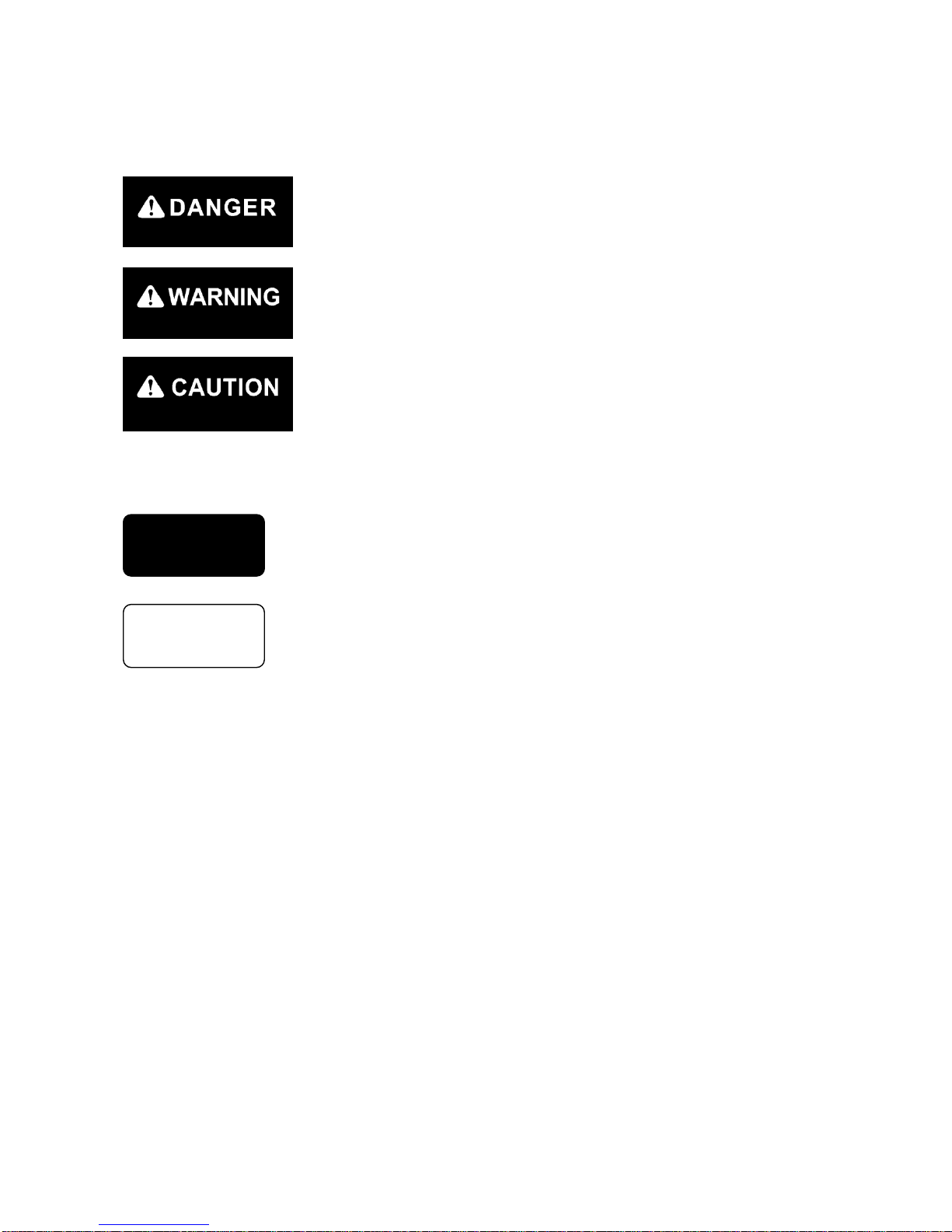
This manual classifies the risks into the following three categories to present the details of the safety
labels in easy-to-understand manner.
This denotes that there is an imminent hazard which will cause serious
personal injury or death.
Follow instructions to avoid danger.
This denotes that there is a hazard which can cause serious personal injury
or death.
Follow instructions to avoid danger.
This denotes that there is a potential hazard which may cause minor or
moderate personal injury or serious damage to this machine.
Follow instructions to avoid danger.
This manual also provides the following to indicate what must be observed for the sake of the machine
and what will be of help.
This denotes that failure to handle the machine properly may damage the
machine or shorten its life.
This denotes helpful information.
This manual covers not only procedures for operation, inspection, and maintenance of this machine, but
also safety precautions where this machine is only used for specified tasks.
Not every event is foreseeable and therefore, cautions given in this manual and on this machine do not
necessarily cover every safety-related issue.
The result of operation, inspection, and maintenance carried out in a way that is not described in this
manual are your responsibility.
Even in the above case, never attempt any work or operation that this manual prohibits you to do.
CAUTION
NOTES

1-4
3. MACHINE OVERVIEW
3.1 SPECIFIED OPERATIONS
This machine is to be used for operation listed below.
• Crane operation
This machine is a mobile crane with a rubber track travelling dolly (carrier) mounted with a boom crane.
This self-propelled crane is capable of moving (travelling) in the worksite and craning an object weighing
within the rated total load.
This is also a remote-controlled crane.
3.2 MACHINE CONFIGURATION
(1) Travelling dolly
(2) Crane
(3) Safety device
Viewed from the operator’s seat, the front, back, left, and right of the
machine are determined in this manual, viewing in the travelling
direction (front) of the machine.
Boom slewing motion is determined with the machine viewed from
immediately above; slew clockwise denotes right-handed motion and
slew counterclockwise denotes left-handed motion.
EXTERNAL VIEW

1-5
This machine is composed of the units listed below.
[1] TRAVELLING DOLLY
This is composed of a travelling gear, engine, travelling operation unit, and crane operation unit.
[2] CRANE
This is composed of a telescoping system, derrick system, hook block, winch system, and outrigger
system.
[3] SAFETY DEVICE
This is composed of the following parts and devices: Over hoist detector/automatic stop device, angle
indicator, hydraulic safety valve, hydraulic automatic locking device, slinging rope detachment protector,
alarm buzzer, audio alarm, level, crane tip-over alarm (an alarm issued in the event of the crane operation
at 3-degree inclination and travelling at 15-degree inclination), travelling lever lock, travelling/crane
selector switch (designed to prevent the machine from craning at travelling), moment limiter (working
envelope limited), working status lamp.
3.3 MACHINE FUNCTIONS
[1] TRAVELLING DOLLY
• This is a compact machine designed to keep the overall width between the crane and outrigger
minimized with them housed (in travelling position).
This compact design is ideal for work in confined areas.
• Two-travelling lever operation enables not only direction changes among forward, backward, and
right/left but pivot turn and spin turn.
[2] CRANE
• An automatic slide outrigger is included in the crane to permit outrigger extension and grounding from
the operator’s station.
• Through the combined use of telescoping, derricking, slewing, and winch system operation, the crane is
capable of raising or lowering the hook block and moving an object weighing within the rated total load
to a designated position within the confines of the working envelope.
• Remote-control units allow remote outrigger setting and remote crane operation.

1-6
4. QUALIFICATION FOR OPERATION
• A high incidence of occupational accidents in crane operation has been reported.
Be aware that experienced engineers are also no exception.
• Warnings and precautions defined in this manual shall be observed for safety assurance
during operation of the machine.
4.1 QUALIFICATION FOR CRANE OPERATION
Only personnel that have obtained the correct training or license stipulated by laws and regulations
applicable to the place of use are qualified to operate this machine.
Contact the relevant government office or our sales service agency for further information.
1-7
5. TERMINOLOGY
5.1 DEFINITION OF TERMS
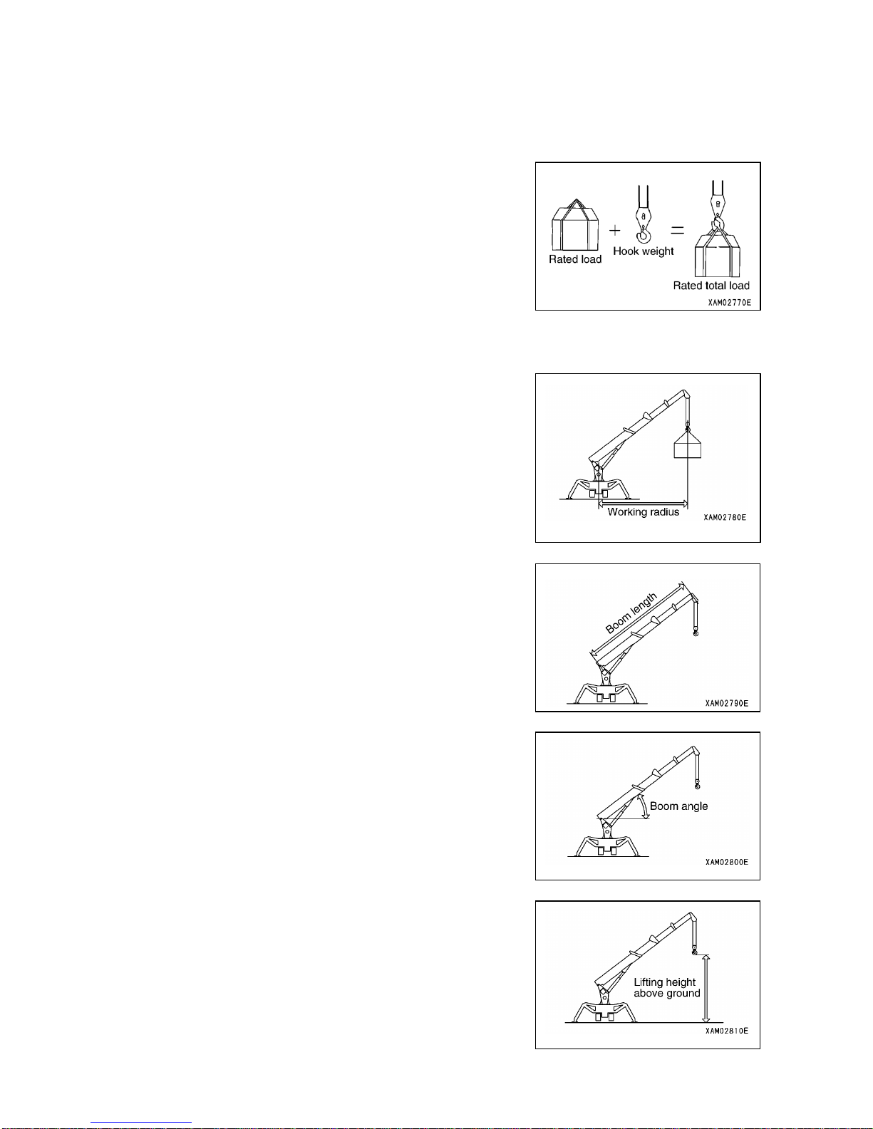
[1] RATED TOTAL LOAD
This is the maximum load that can be applied according to a boom
length and angle. The load includes the mass (weight) of hoisting
accessories (hooks) and slinging ropes.
[2] RATED LOAD
This is a load derived by subtracting the mass (weight) of hoisting
accessories (hooks) and slinging ropes from the rated total load,
which is a withstand load for hoisting.
[3] WORKING RADIUS
This is a horizontal distance between the axis of slewing and the
hook center.
[4] BOOM LENGTH
This is a distance between the boom primary pin and the sheave
pin of the end boom.
[5] BOOM ANGLE
This is an angle which the boom forms with the horizontal plain.
[6] LIFTING HEIGHT ABOVE GROUND
This is a vertical distance between the hook bottom and the ground
with the hook raised to the upper limit.

1-8
5.2 DIAGRAM OF WORKING RADIUS AND LIFTING HEIGHT
• The diagram of working radius and lifting height shows the relationships between the working
radius of this machine, boom angle, and lifting height above the ground with no object
hoisted. The diagram has been made allowing for no deflection in the boom.
• The boom (4) in the diagram of working radius and lifting height represents a state that half of
the “ mark” passes boom (3).
1. Point A denotes a boom angle and point B denotes a lifting
height above ground in the figure at right.
The same working radius is applied to points A and B.
2. The “diagram of working radius and lifting height” shows the
relationships the working radius, boom angle, and lifting
height at no load, allowing for no deflection in the boom.
A deflection occurs in the boom when an object is hoisted,
which causes the working radius to widen slightly.
The rated total load decreases with increase in the working
radius. Actual crane operation requires the planning of work,
allowing for sufficient clearance more than that provided in
the diagram.
1-9
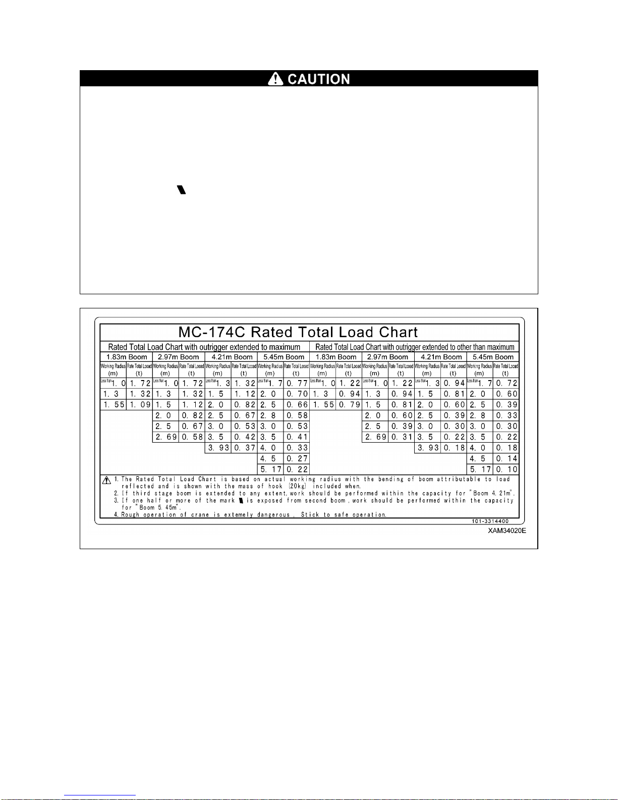
5.3 TOTAL RATED LOAD CHART
• All the values provided in the total rated load chart are based on the assumption that the
machine is placed on a level and firm surface.
The machine may topple over if proper outrigger setting or ground condition fails to be
assured. Exercise due caution when performing crane operation.
• The values in the total rated load chart are determined based on the working radius allowing
for deflection that is developed when load is applied to the boom.
• When extending 3rd boom even if only slightly, crane operation should proceed to the extent
of performance of “4.21m Boom”.
• When half of the “ mark” passes 2nd boom, crane operation should proceed to the extent of
performance of “5.45m Boom”.
• If the working radius exceeds that stated in the table even if only slightly, crane operation
should proceed with respect to the rated total load corresponding to the working radius in the
following table.
• The rated total load is a load including the mass of a hoisting accessory (hook: 20kg).
• When the crane is used with the outriggers extended other than at the maximum, crane
operation should proceed with respect to the values specified in the total rated load chart
corresponding to Rated Total Load Chart with outrigger extended to other than Maximum.
1-10
The total rated load chart provides the maximum loads that the crane is capable of hoisting objects in
parallel with the length of the boom. The loads are specified by working radius.
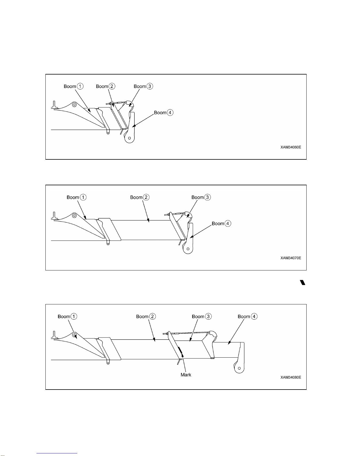
[1] BOOM LENGTH
The following figures illustrate the condition of the booms, “1.83m Boom”, “2.97m Boom”, “4.21m Boom”
and “5.45m Boom” in the preceding boxes in the total rated load chart.
1. “1.83m Boom”: All the booms are retracted.
2. “2.97m Boom”: With booms (3) and (4) retracted, boom (2) is fully extended.
“2.97m Boom” is to apply to crane operation with boom (2) extended even if only slightly.
3. “4.21m Boom”: With booms (2) fully extended, booms (3) and (4) are extended midway (half of the “
mark” passes boom (2)).
“4.21m Boom” is to apply to crane operation with booms (3) and (4) extended even if only slightly.

1-11
4. “5.45m Boom”: All the booms are fully extended.
“5.45m Boom” is to apply to crane operation with half of the “ mark” on boom (3) passes boom (2).
1-12
[2] OUTRIGGER MAXIMUM EXTENSION
• Make sure all the outriggers are placed in the correct position before performing crane
operation.
It is strictly forbidden to perform any crane operation before you place outriggers.
• Always place the machine in a horizontal position with the use of the level when extending the
outriggers. A warning buzzer sounds when the machine is inclined 3° or more and stops when
the machine is placed in a horizontal position.
• Where a crane operation in a condition that outriggers are not fully extended is required, see "
Rated Total Load Chart with outrigger extended to other than Maximum" of the Rated Total
Load Chart. Failure to perform crane operation with proper values may cause the machine to
topple over. Exercise caution when performing operation.
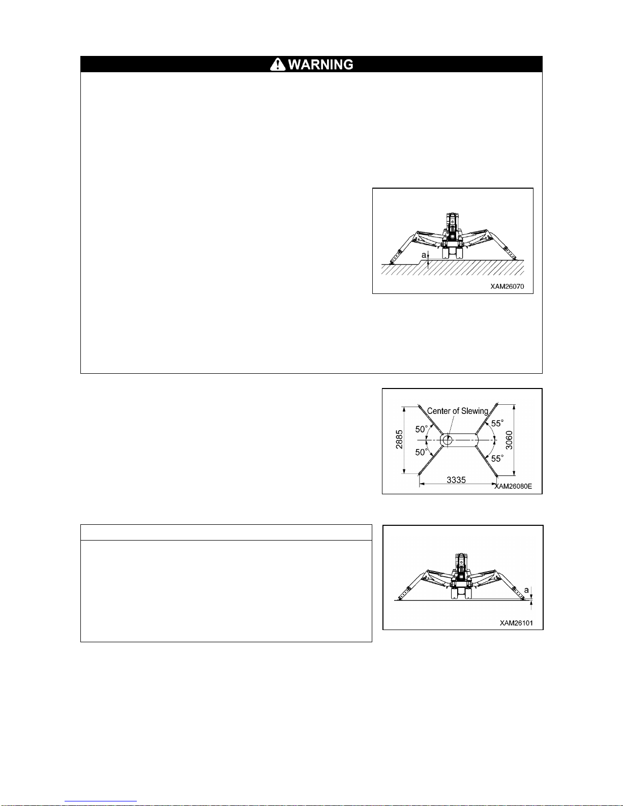
• Despite the maximum extension of all the outriggers, the
width of extended outriggers decreases due to an
ungraded ground even when clearance "a" in the right
figure is 50 mm. Crane operation should proceed with
respect to the values specified in “When the crane is
used with the outriggers extended midway” in the total
rated load chart.
• Where any of the outrigger inner box is retracted into the
outer box, only " Rated Total Load Chart with outrigger
extended to other than Maximum " of the Rated Total
Load Chart is applicable for that crane operation, even
when it is retracted for the length of 1 position pin span.
• The machine becomes unsteady at some point if it undergoes a 360-degree slewing with an
object hoisted. Irrespective of the rated total load, ensure operation is in a short working
radius and at low speed.
The diagram shown on the right represents the condition “When
the crane is used with the outriggers extended at the maximum” in
the total rated load chart.
If the inner box is retracted even if only slightly, crane operation
should proceed with respect to the values specified in the total
rated load chart corresponding to “Rated Total Load Chart with
outrigger extended to other than Maximum”.
See "OPERATION 2.13 OUTRIGGER SET UP OPERATION” for
proper setting of the outriggers.
NOTES
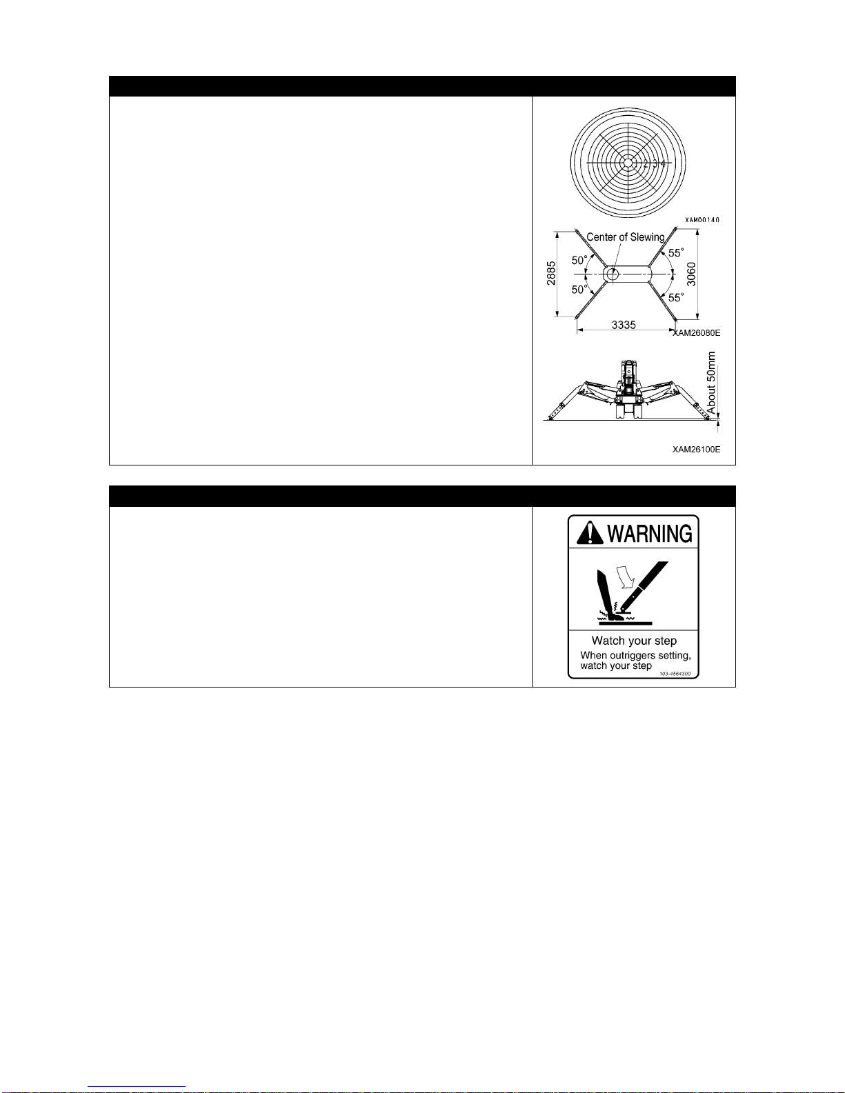
Outrigger maximum extension is defined as that:
1. The outrigger is set at the positioning pin position (55 degrees
front, 50 degrees back).
2. The inner box of all the outriggers is extended fully.
3. All the outriggers are placed on a level surface.
4. Approx. 50mm is assured for clearance "a” (between the
outrigger bottom and crawler bottom) as shown in the figure to
the right.
1-13
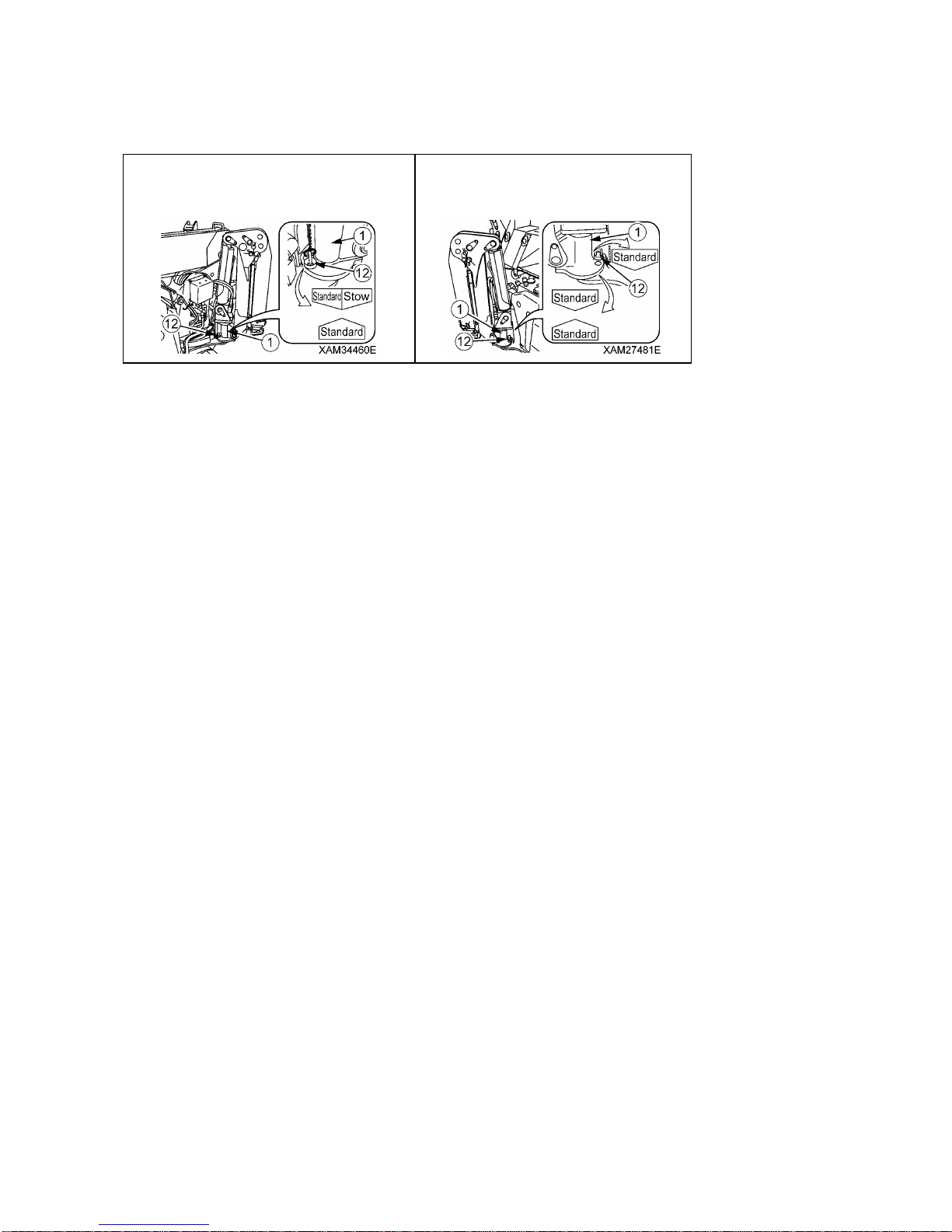
[Placement of outrigger position pins when "outriggers are extended to maximum".]
Figures below shows the placement of outrigger position pins (12) in a condition that "outriggers are
extended to maximum"
The left rear outrigger.
(The right rear outrigger is symmetrical.)
The left front outrigger.
(The right front outrigger is symmetrical.)

1-14
5.4 ANGLE INDICATOR
• Use the Boom angle indicator to check the angle of the boom in operation when the crane is
operated from a distance; using a remote-controller, for instance.
• Before hoisting a load, always see the Rated Total Load Chart to determine the correct boom
length (i.e. number of boom boxes used) and angle, then check the actual weight of the load
with the applicable rated total load and ensure that weight of both of the load itself and sling
utensils never exceeds the rated total load. The Boom angle indicator is helpful to confirm the
boom angle, then,
The Boom angle indicators are attached to both
left and right sides of the No.1 Boom. The
indicator consists of a scale plate and a pointer
as shown in the figure on the right.
Use boom angle indicators as follows:
• Read the figure which the pointer indicates.
The figure shows the "Boom angle" of the
moment.

2-1
SAFETY
1. BASIC PRECAUTIONS 2- 2
2. DRIVING RELATED PRECAUTIONS 2- 7
3. TRANSPORT PRECAUTIONS 2-21
4. BATTERY HANDLING PRECAUTIONS 2-23
5. MAINTENANCE PRECAUTIONS 2-25
6. SAFETY LABEL LOCATIONS 2-32
7. WEEE DIRECTIVE LABEL LOCATIONS 2-39
All the safety precautions defined in this manual should
always be read and observed.
Failure to follow the safety precautions can cause serious
personal injury or death.

2-2
1. BASIC PRECAUTIONS
OBSERVE THE MANUAL AND SAFETY LABELS
• Read thoroughly and understand this manual as well as the safety
labels on various part of this Machine. Attempting to drive/operate
without understanding fully may result in wrong operation that may
cause personal or equipment accidents.
• Fully understand the proper use and inspection/maintenance
procedures, and exercise safe working.
• Make sure this manual and the safety labels labeled on various part
of this Machine are legible all the time.
Whenever illegibility or loss occurs, contact us or our sales service
agency to put the safety label back to the original loca tion.
DRIVING LICENSE
• Full training or a License are necessary to drive this Machine.
Always obtain training or a license before driving.
See “Introduction 4. Qualification for Operation” for details
• Drivers are reques ted to receive educat ion and training of the handling methods and other subjects
from the applicable office, and obtain sufficient driving operation skill before work.
WEAR PROTECTIVE EQUIPMENT AND CLOTHES SUITABLE FOR WORK
• Always put on a helmet, safety shoes and safety belt.
• Select and make sure to put on necessary protective equipment
suitable for the relevant working condition.
• Do not wear loose garments or accessories that may catch
operation levers or protrusions and cause unexpected movement of
the Machine.
COMMIT TO SAFE OPERATION
•Obey the instructions and signs given by the manager and work supervisor, and observe safety first
during the work.
• Obey the crane work basics during work.
• Before starting driving or work, always carry out the inspections.
• Do not work in bad weather for instance strong wind, thunder or mist.
• Do not drive under any circumstances when you are overtired, under the influence of alcohol or after
taking a somnific drug.
• Obey all of the workplace rules, safety regulations and operation method sequences during driving
operations and inspection/maintenance.
• Pay attention to the surrounding conditions and pedestrians all the time when driving or working.
Whenever a pedestrian approaches without taking due care, stop working straight away, and take a
measure such as issuing a warning.
• When driving, be mentally prepared for any unexpected situation and so that you can take measures
immediately.
• Do not attempt any use out of the capabilities and purposes described in this manual under any
circumstance.
• Observe the designated rated total load and work range when driving.
• Do not attempt inattentive driving, harsh driving or awkward operation under any circumstances.
• Remove the key when leaving the machine.

2-3
USE OF MACHINE THAT WAS RENTED OR PREVIOUSLY USED BY SOMEONE ELSE
Check the following subjects in writing before using any Machine th at wa s rented or previo usly u sed by
someone else.
In addition, check the inspection record table for the maintenance conditions such as the periodic
inspections.
(1) Crane capacity
(2) Crane maintenance condition
(3) Behavior and disadvantage unique to the crane
(4) Other subjects that require attention when driving
(a) Operating conditi on of the brakes, crutches etc.
(b) Presence/absence and lighting condition. Checkup of lighting and rotating lamps
(c) Operation condition of hook, winches, boom, outriggers and related items
CHECK SAFETY DEVICES
• Check that all guards and covers are attached properly. Repair immediately if damaged.
• Understand how to use the safety devices well and use properly.
• Do not detach any safety device under any circumstan ces. Keep control to achieve pr oper function all
the time.
• Improper use of safety device may lead to serious bodily accidents.
• Do not trust safety device too much during operation.
FOLLOW INSTRUCTIONS AND SIGNS WHEN WORKING
• When working with the crane, appoint a work supervisor and agree
mutual signs beforehand, and follow the work supervisor and signs
during work.
• When working at a location where many areas are out of view from
the driver, be especially careful to follow the instructions and signs
of the work supervisor and pay attention when driving.
• When working with the crane, the clearance between the boo m and
the travelling dolly and also the gaps between the movable parts of
the derrick cylinder may catch body parts such as an arm or finger.
The driver is requested to make sure no one is within the working
radius of the crane before operating the crane.
PREPARE FOR ABNORMALITY
• Carry out secure inspections and services to prevent accidents.
• Whenever you feel abnormality of the Machine, abort working
immediately, ensure safety and report to the manager.
• Assign in advance who takes which solution to prevent a secondary
accident.
• Do not drive the Machine when fuel or hydraulic oil is leaking from
the Machine. Report to the manager the abnormality, and fully repair
the fuel/hydraulic oil problem before use.
This machine uses gasoline/LPG as its fuel. Pay particular attention
to any fuel leakage.
• Before leaving the Machine, lower the hoisted load to the ground,
stop the engine and remove the engine key.

2-4
TEMPORARY STORAGE WHEN ABNORMALITY IS FOUND WITH MACHINE
In case the Machine is found with an abnormality and is therefore
stored temporarily waiting for service, apply following measures to
notify all people in the office that its use is prohibited due to failure.
• Indicate warning tags on the crane operation lever and other
applicable parts.
Write clearly the information such as abnormality contents, name
and contact of the storage manager, and the term of storage.
• Keep immobile when parked by putting blocks on the rubber tracks
as pawls.
• Remove the engine key and take it with you.
PROVISION OF FIRE EXTINGUISHER AND FIRST AID BOX
Always observe followings to prepare for injuries and fires.
• To prepare for fires, decide the fire extinguisher storage location
and install one, fully read the attached label for the usage and be
prepared for fighting emergencies.
• Decide the location to store the first aid box. In addition, inspect the
first aid box periodically and replenish the contents as necessary.
• Decide the measures to take upon an injury or fire accident.
• Decide how to contact the emergency address (for instance the
emergency physician, ambulance or fire depa rtment), and show the
contact address at designated position so any person ca n make th e
contact.
DO NOT RUSH AND BE CAREFUL WHEN WORKING
• Do not attempt sudden lever operation or harsh driving.
• When two or more cranes work close to each other, drive carefully
while paying attention to accidents such as trips caused by
contacting each other. Also, appoint a guide if necessary for
increased prevention of contact accidents.
• When abnormality or danger occurs during work, abort working
immediately to avoid hazard.
• Stop work under in bad w eather conditions (heavy rain, strong wind,
thunder, thick fog).
Decide when to abort working by seeing the "work abort decision
standard" in the work schedule and by discretion of the work
supervisor of the site.
DO NOT MODIFY
Do not modify the Machine without our written consent under any circumstance.
The modification raises a safety issue, so consult us or our sales service agency beforehand.
We cannot be held responsible for any bodily accident or failure caused by modification that was
performed without consulting us.
2-5
SAFETY WHEN REFILLING FUEL
• This machine operates using gasoline/LPG.
Do not refill with the wrong kind of fuel.
Refilling with the wrong fuel may damage the engine.
• Always stop the engine before refilling fuel.
Refilling the fuel when engine is driving may ca use leaked fuel to
catch fire from hot muffler or other related parts.
• Oversupply of fuel results in spilling and is dan gerous. Refill slightly
lower than the specified level.
Always wipe away cleanly whenever the fuel spills.
• Securely close the tank cap after replenishing fuel.
KEEP FIRE AWAY FROM OIL
Attempt to let a fire approach the fuel, hydraulic oil or engine oil may
result in catching fire. Strictly observe the followings.
• Do not let any fire such as a cigarettes or matches near the
combustibles.
• Securely close all of the fuel and oil container caps.
• Keep the fuel and oils in well-ventilated location.
• Store the fuel and oils in a fixed location and keep unauthorized
persons away.
• Do not leave the site when replenishing the fuel or oil.
Be especially careful to observe "Safety when refilling fuel"
described earlier when replenishing fuel.
• Cleanly wipe away any fuel or oil spilled during replenishment.
HANDLING IN HIGH TEMPERATURE
For a short time after ceasing operation of the Machine, the engine
itself and engine oil, cooling water and hydraulic oil will have a high
temperature, and in addition the pressure is accumulated inside the
hydraulic oil tank.
Any attempt to inspect the engine, remove the radiator cap, drain oil,
drain water or replace the filter under such condition may result in
burns.
Wait until the temperature cools, then carry out the following
procedure.
1. To prevent emission of the high temperature oil, stop the engine
and wait until the oil temperature drops.
2. Loosen the bolts so that the cap is raised a little to allow the
release of inner pressure.
3. Remove bolts and then remove cap.
(To find how much the oil temperature dropped, hold your hand near
the surface of the hydraulic oil tank or similar location without actually
contacting and find out from the ambient temperature.)

2-6
BEWARE OF ASBESTOS DUST
Inhalation of air containing asbestos may result in lung cancer. This
Machine does not use any asbestos, but asbe stos may be contained
in the wall, ceiling or other part of construction within the work area o f
this Machine. In addition, be careful of the followings when working
with a material that may be using asbestos.
• Put on designated dust free mask and/or other equipment as
necessary.
• Do not use compressed air for cleaning.
• Spray water when cleaning to prevent asbestos dusts from flying
into air.
• Always work downwind when driving the Machine at a site that may
contain asbestos dusts.
• Strictly observe the assigned rules related to the working site and
environmental standard.
CRANE INJURY PREVENTION
Do not let whole or part of your body enter any of the following
clearances, since such act may cause serious bodily accidents.
• Between the boom and the travelling dolly.
• Between the outrigger support and the ground contact surface.
• Between the boom/post and the derrick cylinder.
• Between the winch drum and the wire ropes.
• Between sheaves and wire rope.
• Between the crawlers and the ground.
BEWARE OF EXHAUST GAS
When starting the engine or handling fuel/cleaning oil/paint indoors or
at a location with bad ventilation con dition, prevent gas-poisoning risk
by improving the ventilation by opening the windows and exits.
If the ventilation is insufficient even after opening the windows and
exits, set up a ventilation fan.
2-7
2. DRIVING RELATED PRECAUTIONS
2.1 BEFORE STARTING THE ENGINE
ESTABLISH SAFETY OF THE WORKING SITE
• Confirm that no danger is present at the working site before starting
work.
• Investigate the ground and road surface condition of the working
site and decide the best working method.
• Flatten the inclination of the working site as much as possible before
starting work. Also, if sand and gravel are excessive, hose down
before work.
• When working over the roadway, place guides or surrounding
barriers, to ensure the safety of traffic, vehicles and pedestrians.
• Prevent people from entering the working site and apply measures
to prevent people from approaching.
Attempting to approach a moving Machine may result in hard
collision by contact or pinching, and may result in serious bodily
accidents and deaths.
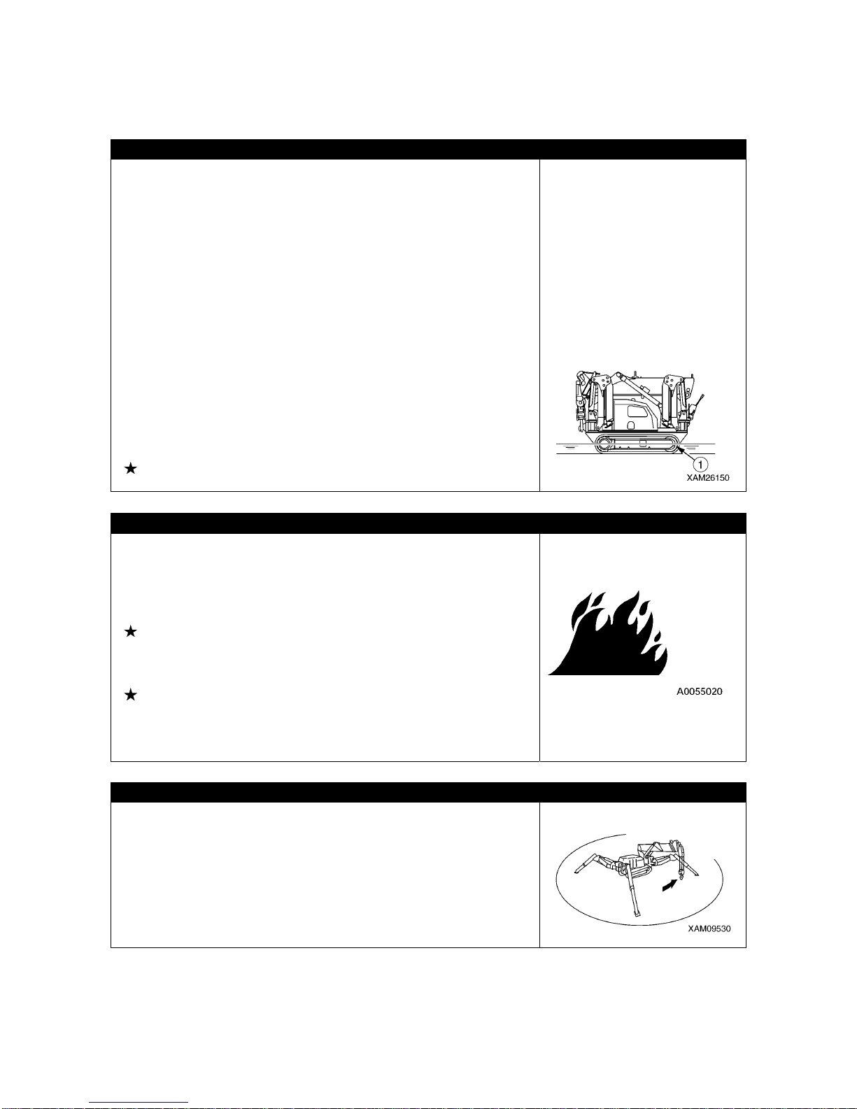
• When travelling in the water or crossing over shallow water, check
the ground condition, depth and water velocity beforehand and
make sure not to exceed the allowable water depth (no higher than
center of idler (1)).
See “Operation 2.12 [2] Allowable Water Depth” for details
INSPECTION BEFORE STARTING ENGINE
Execute following inspections before the first engine startup of the
day.
Omitting these inspections m ay result in serious bodily accidents.
• Inspect for fuel/oil leak, accumulation of combustibles around the
engine and battery systems, and similar phenomenon.
See “Operation 2.1 Checks Before Operation” for details.
• Inspect the fuel quantity, cooling water quantity, hydraulic oil tank
quantity, air cleaner blockage, electrical wiring damage, and check
operations of safety devices and instruments.
See “Operation 2.1 Checks Before Operation” for details.
• Make sure the operation levers are at neutral position.
Check that the operation linkages operate adequately.
Always repair if any result of the above is faulty.
CAUTIONS WHEN STARTING ENGINE
• Make sure no person or object is within the boo m swing radius area
before starting engine.
• Blow the horn for warning before starting the engine.
• Do not start the engine by short-circuiting the starter circuit. Such
actions may cause a fire.
2-8
2.2 AFTER STARTING THE ENGINE
INSPECTION AFTER STARTING THE ENGINE
Omitting the inspections after starting the engine results in delay to notice any machine abnormalities,
and may result in bodily accidents and Machine damage.
Inspect a wide area to ensure no obstacles, also ensure people are prevented from approaching the
Machine.
• Inspect the equipment operation conditions, Machine travelling conditions, outrigger operation
conditions, winch winding up and down, boom derricking, and crane operation conditions such as
extension, retraction and swinging.
• Inspect the sound, vibration, heat and odor o f the Machine , an d che ck for instrument er rors, a ir lea ks,
oil leaks, fuel leaks and other bad factors. Be extra careful with fuel leaks.
• Always repair broken part whenever an abnormality is found.
Attempt to use without servicing may result in unexpected bodily accidents and/or Machine failures.
CAUTIONS WHEN STARTING TO MOVE THE MACHINE
To prevent serious injuries and death accidents, always execute the
followings before moving the Machine.
• Set the Machine to the travelling position in the right diagram.
Do not travel when the hook block is not contained.
• Ensure the boom is fully lowered and retracted.
• Fix the hook block into the containment position.
• Ensure the outrigger is contained.
See “Operation 2.5 Machine Travel Position” for details.
• Make sure again that no one or object is in the vicinity before
starting to move.
• Blow the horn for warning before starting to move .
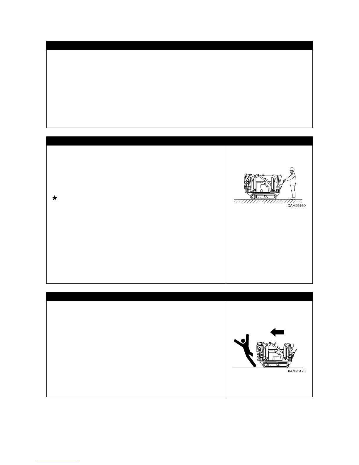
• When travelling, be sure to stand in front of the travel lever located
on the travel control panel side. When the machine starts moving,
walk and keep your pace with the machine speed.
• The Machine is prohibited to travel when a person or load is on the
travelling dolly or the boom.
• When travelling, stow hook and outrigger, and make sure of the
surrounding safety.
• When stowing outriggers, insert each position pins completely to
lock.
CAUTIONS WHEN MOVING FORWARD/BACKWARD OR CHANGING DIRECTION
Always observe followings to prevent serious injuries and death
when moving the Machine.
• Drop the speed early and wait until the Machine stops before
changing from forward to backward, or backward to forward.
• Blow the horn and alert the people nearby before changing
between forward/backward movements or changing direction.
• Check that no one is around the Machine.
The front of the Machine frame requires special attention because
certain areas of vision are blocked, so stop the Machine as
necessary and make sure no one is at front or around.
• Place a guide if the location is hazardous or with a bad view.
• Make sure to prevent people from crossing the moving direction or
in the direction to be changed.

2-9
CAUTIONS WHEN TRAVELLING
Always observe the following to prevent serious injuries, fatal
accidents when the Machine is travelling.
• Do not attempt looking sideways or other dangerous acts when
driving.
• Do not over speed, start moving suddenly, stop suddenly, swing
suddenly or meander since such acts are dangerous.
• When travelling backward, the operator should be extre mely careful
of uneven ground. Lower the speed and drive the machine care fully
and take care not to get trapped by bumps or other obstacles.
• Whenever you find a machine abnormality (sound, vibration, odor,
instrument error, fuel le ak, water le ak or oil leak), imm ediatel y park
the Machine in a safe location and inspect the cause.
• Do not suddenly change the direction. Doing so may cause the
Machine to lose balance or damage the machine or nearby objects.
• When travelling over uneven terrain, change travel speed mode to
"low speed" to travel as slow as possible to prevent tripping, and
avoid acute operation when changing the direction.
• Avoid moving over obstacles as much as possible.
Change travel speed mode to "low speed" and travel as slowly as
possible when moving over an obstacle for unavoidable reason.
Also, do not move diagonally over obstacles th at cause the Machine
to tilt excessively (10 degrees or more).
• When travelling, ensure extra clearance to prevent accidental
contact with other machinery or objects.
• When travelling in water or crossing over shallow water, check the
ground condition, depth and water velocity (never attempt to enter
into flowing water) beforehand and make sure not to exceed the
allowable water depth (no higher than center of idler (1)).
See “Operation 2.12 [2] Allowable Water Depth” for details.
• Check weight limits against the Machine mass before crossing over
a bridge or construction that is private property. In case of public
road, ask the applicable road management administration and
follow the given advice.
• Do Not travel with load hoisted.
BE CAREFUL WHEN TRAVELLING OVER SLOPES
ALWAYS observe followings to prevent serious injuries, death or
accidents when travelling over a slope for unavoidable reason.
• Be careful of tripping and skids when travelling over slope.
• Do not change orientation on or horizontally when travelling over
slope. Practice safe travelling by for instance lowering to the flat
land and divert.
See “Operation 2.12 [3] Cautions on Upward/downward slope”
for details.
• Skids happen more than you think on grass, fallen leaves, and on
wet steel plates.
Avoid the Machine from being horizontal over the slope as much as
possible, and decrease the speed sufficiently.
• Travel slowly in low speed when travelling downhill, after changing
travel speed mode to "low speed". In addition, apply brake (by
setting the travel lever to neutral) as necessary.
2-10
BE CAREFUL OF TRIPPING ON UNSTABLE GROUND
Always observe the following to prevent serious injuries and fatal
accidents when travelling over unstable ground for unavoidable
reason.
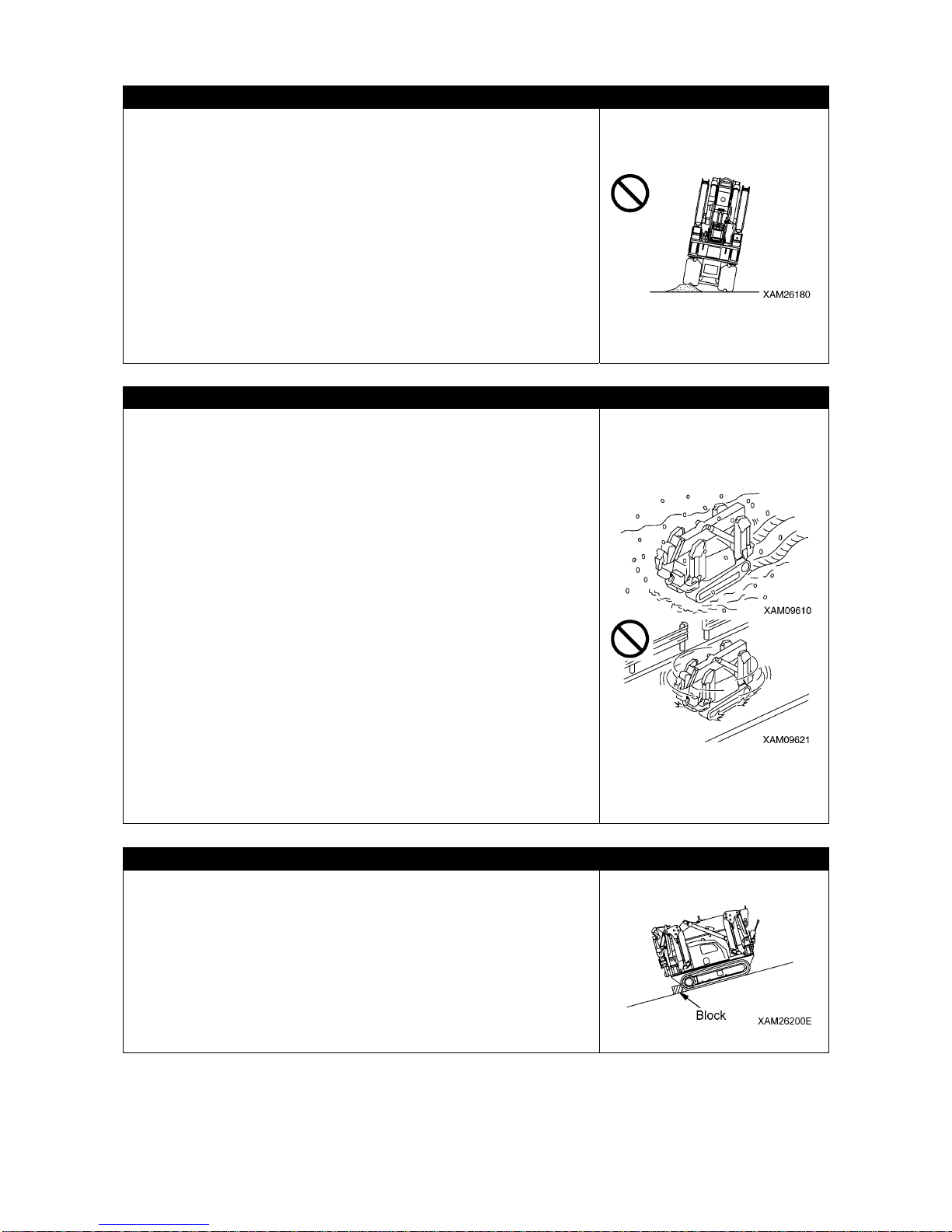
• Do not enter soft grou nd area. T he Machi ne is diffi cult to e vacuate
from such area.
• The ground near cliff, roadside and deep gully is unstable, so avoid
going near such ground as much as possible.
The Machine may trip or fall when the ground loosens due to mass
and/or vibration of the Machine. Be especially careful that the
ground is likely to loosen after rain, use of dynamite or earthquake.
• Avoid going near the earth fills or dug gutters that are unstable.
Crumbles caused by mass and/or vibration of the Machine may
cause the Machine to tilt.
CAUTIONS WHEN THE GROUND IS COVERED IN SNOW OR FROZEN
Always observe the following to prevent serious injuries and fatal
accidents when travelling over a snow covered ground or frozen road
for unavoidable reason.
• The snow covered ground and frozen roads cause slips even when
the inclination is small, so decrease the speed when travelling and
avoid starting suddenly, stopping suddenly and swinging suddenly.
Uphill and downhill are especially likely to cause slips and thus
dangerous.
• Ground of the frozen road becomes soft when the air temperature
rises and causes the machine travel and other operations to be
unstable. Be very careful.
• Under cold weather, check that the lo ad to be hoisted is not frozen,
stuck to the ground or any other surface. Attempting to hoist without
knowing the load is frozen, stuck to the ground or any other surface
is dangerous.
• Do not directly contact metal surface with your body part such as a
finger or hand under cold weather.
Attempt to contact the metal surface of the Machine under harsh
cold weather may cause the skin to stick to the frozen surface.
• Remove snow and/or ice laid on the Machine that causes the safety
nameplates to be hard to read. Be especially careful to securely
remove those that are on the boom and thus may fall.
CAUTIONS WHEN PARKING
• Park at a location where the ground is level, ro ck falls and landslides
do not occur, if it is a lowland check that flooding does not occur.
• If you must park on a slope for an unavoidable reason, use blocks
as pawls to immobilize the Machine.
• When parking on the street, place flags, protection barr iers, lightin g
and caution notices that do not interfere with the traffic, so that other
vehicles are aware.
• Stop the engine before leaving the Machine.
Always remove the starter key and store in a fixed location.
• When parking, the lock lever must be placed to “Lock”.

2-11
PRECAUTIONS IN COLD WEATHER
• Remove snow from and defreeze the swing gear, boom and winch
related parts, and check the movements before work.
• Warm up thoroughly.
Attempting to operate the operation levers and switches without
enough warm-up will cause the Machine to be slow in reaction, and
may result in unexpected accidents.
• Avoid acutely accelerating the engine shortly after starting the
engine.
• Increase the oil temperature of the hydraulic circuit by relieving the
oil pressure (let the pneumatic oil escape to the hydraulic oil tan k by
raising it above the hydraulic circuit set pressure) by using operation
lever. Doing so improves the Machine reactions and prevents
improper operations.
• If the battery fluid is fro zen, do not charge battery or start the engine
using other power source.
Such acts may cause the battery to catch fire.
Before charging or starting up using other power source, defreeze
the battery fluid and check that failur e s such as battery fluid leak do
not exist.
• After end of the work, wipe off and apply wraps if substances such
as condensation, snow or mud are stuck to the wire harness,
connector (1), switches, sensors or similar part.
If the infiltrated condensation and/or similar substance freezes, the
Machine may not operate properly upon the next use and cause
unexpected accidents.

2-12
2.3 WORKING WITH THE CRANE
INSPECTION BEFORE STARTING WORK
Check that the safety devices and crane operate properly.
• Operate each of the operation levers and switches under no load, and check operations are perfor med
normally.
Repair immediately if any abnormality exists.
• Check that the safety devices such as the moment limiter, and over hoist detector device activate
properly.
CAUTIONS WHEN HANDLING MOMENT LIMITER
• Use/store the moment limiter under the following ranges of ambient temperature.
Temperature of use: 10 to 50 °C Storage temperature: -20 to 60 °C
• Avoid direct sunlight so that the temperature of the moment limiter body does not exceed the range.
• Avoid locations with strong acid or alkaline atmosphere as much as possible. Otherwise, unexpected
failures may occur.
• Do not apply impact to the moment limiter body for instance by colliding with an object.
Such attempt may damage the case and may result in failures and improper operations.
• Do not push the panel sheet of the moment limiter body by a force more than necessary or push with
sharp object such as a tip of a screwdriver. Such action may damage the panel sheet and may result in
failures and improper operations.
• Do not remove the case cover or panel sheet from, or disassemble the moment limiter body. Such
action may damage the case and/or panel sheet and may result in failures and improper operations.
CAUTIONS WHEN SETTING UP MOMENT LIMITER
• The moment limiter calculates the moments assuming the Machine is level.
If you work with the crane when the Mac hine is not level, warnings and alarms a re not issued even
when the rated total load is near.
Always set the outrigger horizontally to the ground while looking at the level gauge.
• Before using the crane, check that the boom angle di splay, boom length display and real load display
of the moment limiter are displayed correctly following the crane movements. At tempting to use wi thout
the correct display res ults in failure to obtain correct measurement result and may result in serious
bodily accidents caused by improper operation and/or breakage of nearby equipment.
• Always make sure the wire strand sett ing of the mome nt limiter matches wit h the wire strand of the
crane. If the wire strands do not match, always let the wire strands match by changing the wire strand
setting of the moment limiter or by changing the wire strand of the crane. Attempting to use with
unmatched wire strands results in failure to obtain correct measurement result and may result in
serious bodily accidents caused by improper operation and/or breakage of nearby equipment.
• Do not carelessly change the setting when measuring with the moment limiter. Such action results in
failure to obtain correct measurement result and may result in serious bodily accidents caused by
improper operation and/or breakage of nearby equipment.
PLACE CRANE ON LEVEL AND HARD GROUND
• Always place the outriggers on a level, stable and solid ground.
Attempt to work with crane without outriggers firmly contacting the
ground may cause the Machine to trip.
• Always place all outriggers before working with crane.
• Do not set any outrigger near the location that may collapse, for
instance, soft ground, roadside or drilled hole.
In case the outriggers need to be placed on soft ground for an
unavoidable reason, always reinforce the ground by laying a
sufficiently large and strong base plate below each of the outrigger
supports.
2-13
CHECK OUTRIGGER PLACEMENT CONDITION
Always observe followings to prevent serious injuries and fatal
accidents when placing the outriggers.
• When placing the outriggers, always keep the Machine level while
looking at the level gauge. Occasionally view the level gauge and
make sure to keep the Machine level during the crane works as well.
• Place the outriggers at a maximum extension condition as the basic
rule.
In case of placing in a non-maximum extension condition for
unavoidable reason, always find the values outrigger extended to
other than maximum value in the total rated load chart before work.
• Place the outriggers so that the rubber tracks are approximately 50
mm above the ground.
• Make sure all of the outrigger position pins are securely fixed.
CAUTIONS WHEN PLACING THE OUTRIGGERS
Do not let people approach nearby when placing the outriggers.
Otherwise serious accidents, for instance the outrigger support
catching a foot, may occur.

2-14
BEWARE OF ELECTRICAL CABLE ABOVE
• Do not let the Machine come into contact with overhead electrical
cables.
High voltage cables may inflict electrical shock just by being nea r to
them.
• People who throw objects are likely to suffer electrical shocks.
Always observe following to prevent accidents.
• If the boom or the wire ropes may come into contact with an
electrical cable in the workplace, consult the electricity company
and make sure that the measures (for instance security personnel
or the application of w rap tubes and warning ta gs to the elect rical
cable) stipulated by the related regulations are taken before
starting work.
• Wear rubber soled shoes and rubber gloves, and be careful that
the body parts unprotected by rubber or other insulation do not
come into contact with the wire rope or the Machine frame.
• Place a guide and let him/her watch so that the boom, wire rope or
Machine frame does not ge t too near to the electrical cable.
Before beginning work, decide on the emergency signs and other
necessities.
• Ask t he e lect ricit y c ompan y f or t he vo lt age i n t he el ect ric al c ables
in the working site.
• Ensure the offset distances (safe distance) shown in the following
table between the boom/Machine frame and electrical cables.
Voltage of
Electrical Cable
Minimum Safe
Distance
Low voltage
(Distribution line)
100・200V
2m
6,600V 2m
Special
(Transmission
line)
22,000V 3m
66,000V 4m
154,000V 5m
187,000V 6m
275,000V 7m
500,000V 11m

2-15
MEASURES WHEN CHARGE ACCIDENT OCCURS
When an electrical charge accident occurs do not panic and follow the steps below:
1. Report
Immediately report to the electricity company or related management company, and receive
instructions on how to stop the power transmission, emergency procedures and any other steps.
2. Evacuation of related personnel from vicinity of Machine
Remove related personnel from around the Machine to prevent secondary disasters.
Personnel who suffered electrical shock by holding a sling rope, guide rope or other conductor when
the Machine was charged should evacuate by his/her own effort.
Do not try to help such person. Otherwise, secondary electrical shock accident occurs.
3. Emergency procedure
Take the solution by following sequence in case of urgency where personnel received electrical shock
because the Machine was charged.
(1) If the Machine can be operated, immediately operate the Machine to move the Machine
constructions away fr om the cont act and out of th e range of t he cause of t he charge. B e careful
not to touch the distribution power cable.
(2) Evacuate th e M ac hi n e com pl et el y away from the cause of the charge, make sure the Machine is
not charged, rescue the electrically shocked personnel and immediately transport them to the
hospital.
4. Measure after accident
After accident, do not reuse as is. Such attempt may cause unexpected accidents and enhances
failures.
Ask us or our sales service agency for repair.
CAUTIONS WHEN WORKING WITH CRANE IN LOCATION WITH HIGH OUTPUT
MICROWAVE EMISSION
Working with the crane near a high output microwave emission equipment such as a radar or TV/radio
broadcast antenna causes the crane construction to be exposed to the microwave and generates
induced current, therefore is very dangerous. In addition, the mechatronics may become haywire.
Establish grounding between the Machine frame and the ground when working in such location. In
addition, slingers are requested to wear rubber boots and rubb er gloves since risk of electrica l shock by
contacting parts such as the hook or wire exists.

2-16
PAY ATTENTION TO WEATHER INFORMATION
• In case of thunderstorm, there is a risk o f lightnin g, so abort w orking with crane, immediately lowe r the
load and contain the boom.
• Exposing the hoisted load to wind causes the load to move and causes the Machine to be unstable,
thus is dangerous. Immediately lower the load and contain the boom when the wind is causing the load
to move.
• If the maximum instantaneous wind speed is 10 m/s or grea ter, abort wor king with crane, immed iately
lower the load and contain the boom.
• Even when the maximum instantaneous wind speed is below 10 m/s, the bigger the hoisted load,
higher the hoisted load position, and longer the boom, the wind effect increases accordingly. Be fully
careful during work.
• When a load such as a steel plate that has a large area exposed to wind is being hoisted, the wind
arriving from front/rear/side of the boom may cause the Machine to trip or damage the boom. Be fully
careful when working.
• When an earthquake occurs, abort working and wait until the earthquake is over.
The following table indicates approximate rela tion between the wind speed and wind effe ct. The wind
speed mentioned in the weathercast is mean wind velocity (m/s) during 10 m at 10 m above the
ground.
Force Wind Speed (m/s) Effect On Land
0 Less than 0.3 Smoke rises vertically.
1 0.3 - below 1.6 Wind motion visible in smoke.
2 1.6 - below 3.4 Wind felt on exposed skin.
3 3.4 - below 5.5 Leaves and smaller twigs in constant motion.
4 5.5 - below 8.0 Dust and loose paper raised. Small branches begin to move.
5 8.0 - below 10.8 Smaller trees sway. Some foam and spray.
6 10.8 - below 13.9
Large branches in motion. Whistling heard in overhead wires.
Umbrella use becomes difficult.
7 13.9 - below 17.2 Whole trees in motion. Effort needed to walk against the wind.
8 17.2 - below 20.8 Twigs broken from trees. Progress impeded.
9 20.8 - below 24.5 Light structure damage. Slates blown off.
10 24.5 - below 28.5 Trees uprooted. Considerable structural damage.
11 28.5 - below 32.7 Widespread structural damage.
2-17
CAUTIONS WHEN SLINGING
• Check the following before hoisting a load.
Attempt to hoist the load without checking may result in serious bodily accidents by a drop of the load
or tripping.
• Observe the values in the total rated load chart.
• Hoist from the center of gravity of the load.
• Check that the wire ropes of the hook block are perpendicular to the ground.
• When the load leaves the ground, stop winding up the load once and check whether the load is
stable.
• Before hoisting a slung load, always check whether the sling wire rope "retainer device" of the hook
block is hung securely. If the "retainer device" is no t hung, the w ire rope may leave the hook blo ck and
cause the load to fall and results in a serious accident.
• Larger wire rope angle when hoisting the load increases for ce that applies to the wire ro pe even when
the load weight is unchanged, thus may cause the wire rope to snap. Pay consideration when slinging
to prevent excessive force being applied to the wire rope.
• Do not hoist more than one load at once.
Such attempt may cause the hoist bra cket to h it and damage th e other hoisted loa d, the loa ds to move
and loose balance and fall or cause other serious accidents.
Do not hoist more than one load even if the total is within the rated total load.
• Hoisting of lengthy load causes the load to lose balance and is dangerous.
In case such load, hoist vertically by using a clamp, or achieve balance o f the hoisted load by applying
a rope to both ends of the load.
CAUTIONS WHEN HANDLING WIRE ROPE
• The wire rope wears out ov e r time, so inspect before each job, and
replace immediately if at or beyond the replacement standard.
At the same time, inspect the sheave at the tip of the boom and the
sheave of the hook block. Damaged sheaves accelerate the
damage of the wire ropes.
• Use the wire ropes specified by us.
• Always put on leather gloves when handling the wire rope.
• Handing worn and damaged wire may cause injury by wire splinter.
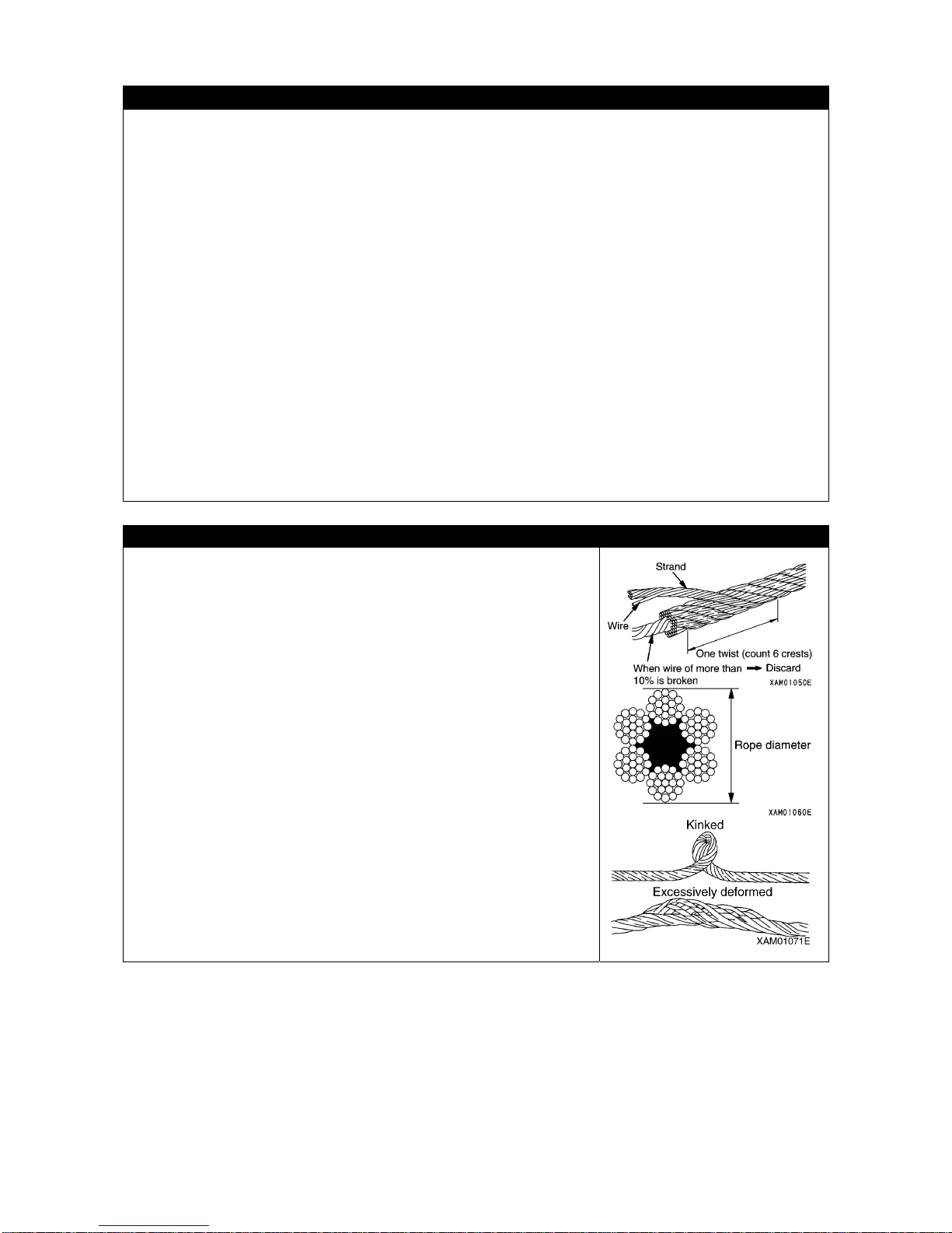
• Do not use any wire rope of which any of the followings apply.
• 10% or more of the wires (except the filler wires) in one twist of the
wire rope are snipped.
• The wire rope diameter abrasion is beyond 7% of the nominal
diameter.
• Is kinked.
• Is excessively deformed or corroded.
• Affected by heat or sparks.

2-18
CAUTIONS WHEN WORKING WITH THE CRANE
• Be sure to verify that the emergency stop cancel switch is at OFF (auto) position be fore operating the
crane.
Do not attempt the crane operation when the emergency stop cance l switch is at ON (cancel) position.
The emergency stop cancel switch is permitted to be at ON (cancel) position only during the inspection
or maintenance works.
• Attempting to work beyond the capacity of the Machine may cause serious accidents and failures
caused by for instance tripping or flu ctuation. Obse rve the total rated load ch art when working with the
crane.
• Do not travel with a load being hoisted under any circumstance.
Such attempt may cause the crane to tip and may re sult in serious bodily accidents.
• Be slow when operating the crane.
Sudden lever or accelerator operations may cause risks such as the load moving, falling or colliding
with nearby objects. Be especially careful to be slow during the swing operations.
• Do not let people approach the work radius or below the load, since risks such as fall of the load and
contact with the load exist. Such attempt may result in serious bodily accidents. Also, during the work,
consider the fact that the working radius increases when the load is hoisted and the boom is deflected.
• Attempting to work with the cra ne eve n wh en the vi ew is bad due to loca tion or weather is dangerous.
Ensure brightness by posting a work lamp or other illumination facility in dark places.
When the view is bad because of bad weather (rain, fog, snow), abort working and wait until the
weather recovers.
• Do not use for any other purpose than indicated, for instance raising a person using a crane.
• If the overwinding detector alarm buzzer is heard, immed iately remove your hand fro m the winch lever .
The hook block winding stops. Then, operate the winch lever to Down (push forward) to wind down the
hook block. In addition, the hook block is wound up when the boom is extended, so be sure to ensure
extra clearance between the boom and the hook block during work.
• When the boom extends, the hook block is wound up.
Operate the winch lever to Down (push forward) to wind down the hook block while you extend the
boom.
• Whenever an overload occurs during work, lower the load by winding down the winch by setting the
winch lever to Down (push forward).
Do not raise or lower the boom suddenly. Such an attempt may cause serious accidents by tripping.
• The volume of the hydraulic oil in each of the cylinders changes depending on the temperature.
By leaving idle with a load being hoisted, as the time passes by the oi l temperature drops and the
hydraulic oil volume decreases, and changes may occur such as the boom derrick angle decreasing
and the boom length decreasing.
In this case, stop boom derricking operations and boom extension operations in order to correct.
• Do not leave the driving operation position when a load is hoisted.
Lower the load before leaving the Machine.
• Keep the hook block wound up when not in use.
Otherwise, anyone near the load may collide with the hook block.
• Operator must not leave operators seat during operation.
2-19
CAUTIONS WHEN OPERATING WINCH
• Do not allow anyone below the hoisted load.
• When hoisting a load, always stop at the "takeoff" position where
the hoisted load leaves the ground. Check subjects such as load
stability and load force, then hoist up the load.
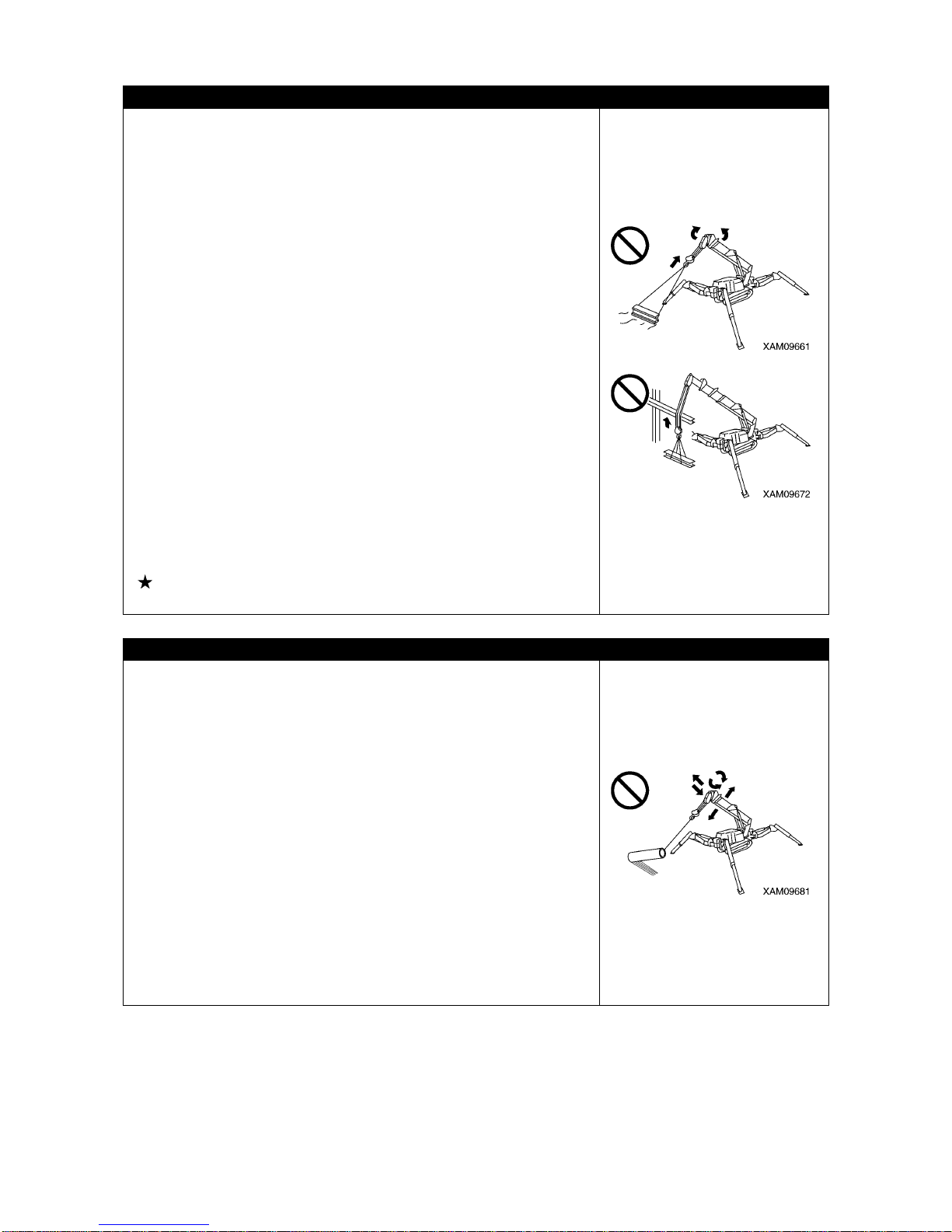
• Do not pull laterally, pull toward you or hoist diagonally. Such
attempt may cause the crane to trip or suffer damage.
• Overwinding of the hook block may re sult in collision with the boom,
snipping the wire ropes and causes the hook block and load to fall
and cause serious accidents. Be extra careful to prevent
overwinding of the hook block.
• Be careful to prevent the wire rope and/or hoisted load from
contacting an obstacle such as a tree or steel structure when
hoisting a load.
If caught by an obstacle, do not forcibly wind up the hoist load, but
untangle the caught part before winding up.
• Do not operate the winch system if the rope is badly wound on the
winch drum (tangled). If tangled the rope may be damaged,
shortening its life span, and there is a possibility that it may break
and cause a serious accident. Observe the followin g precautions to
avoid the rope becoming tangled:
• Do not let the hook block hit the ground.
• Before leaving the hook block lowered for a long time for instance
when working with underground, leave at least three loops of wire
rope in the winch drum.
• If the wire rope is twisted and causes the hook block to turn, fully
eliminate the twist before work.
See “ Operation 4. What to do with Twisted Winch Wire Rope” for
details.
CAUTIONS WHEN OPERATING THE BOOM
• Operate the boom operation lever as slowly as possible .
Especially avoid sudden lever operations when the load is hoisted,
which may cause the load to move and give large impact to the
Machine, and thus may damage the crane or trip the Machine.
• When the boom is lowered, the working radius increases, and the
rated total load that can be hoisted decreases. When working while
raising/lowering the boom, pay extra attention to ensure that the
mass (weight) of the load at the time the boo m is most lowered does
not cause overloading.
• Attempts to pull the load laterally or pull to bring forth the load by
raising/lowering and/or extracting/retracting operation of the boom
are prohibited. Do not attempt under any circumstance.
• Be aware of the hook block windup condition and exercise caution
when extending or retracting the boom.
• When the boom is extended, the working radius increases, and the
rated total load that can be hoisted decreases. When working with
extending/retracting the boom, pay extra attention to en sure that the
mass (weight) of the load at the time the boo m is most lowered does
not cause overloading.

2-20
CAUTIONS DURING SWING OPERATION
• Check the safety in the vicinity and blow the horn before swing ing.
• If the boom derrick angle is small, be careful to prevent the boom
from hitting the driver or the Machine.
•Operate the swing lever as slowly as possible. Make sure to start
smoothly, swing slowly, and stop quietly.
Especially avoid sudden lever operations when the load is hoisted,
which may cause the load to move and cause the Machine to lose
balance, and thus may damage the crane or trip the Machine.
• Attempts to pull to bring forth the load or let the load stand up by
swinging operation are prohibited. Do not attempt under any
circumstances.
• Be careful to prevent the wire rope and/or hoisted load from
contacting an obstacle such as a tree or steel structure when
hoisting a load or when swinging.
If caught by an obstacle, do not forcibly wind up the hoist load, but
untangle the caught part before winding up.
• Certain outrigger extension condition may cause the boom to hit an
outrigger and cause the crane to be damaged or the Machine to trip.
Be careful to prevent the boom from hitting outriggers during swing
operation.
COOPERATION HOISTING IS PROHIBITED AS THE RULE
Cooperation hoisting, that is to use more than one crane to hoist a load, is prohibited.
The cooperation hoisting work is a highly hazardous work that may cause for instance a trip of the
Machine due to uneven center of gravity, fall of the hoisted load or boom damage.
If the need for such work in unavoidab le, e stablish a wor k scheme by re spo nsibility o f the user , discu ss
fully, let the worker fully acknowledge the work method and procedures, then work carefully under the
direct leadership of the work supervisor.
Also observe the following cautions:
• Use cranes of same model.
• Choose a Machine model that can handle sufficiently larger loads than the load to be hoisted.
• Make sure only one person gives signs.
• Limit the crane operations to single operations as the rule, and do not attempt any swing operation.
• Appoint one responsible slinger who is most experienced.
WORKING AT A SITE WITH UNDERGROUND LIFTING
• Leave at least three loops of wire rope in the winch drum when winding down the wire rope in case of
underground work or similar occasion. This Machine is equipped with three-winding stop alarm /
automatic stop device as the safety device, but even then be care ful to prevent this safe ty device from
activating.
• Make sure signs are communicated ful ly.
• Be especially careful with the crane operations.
2-21
3. TRANSPORT PRECAUTIONS
CAUTIONS WHEN LOADING OR UNLOADING
• Be especially careful when loading or unloading the Machine
because of the risks.
• Select a location that is level and has firm road surface when
loading or unloading the Machine. In addition, keep enough
distance from the roadside.
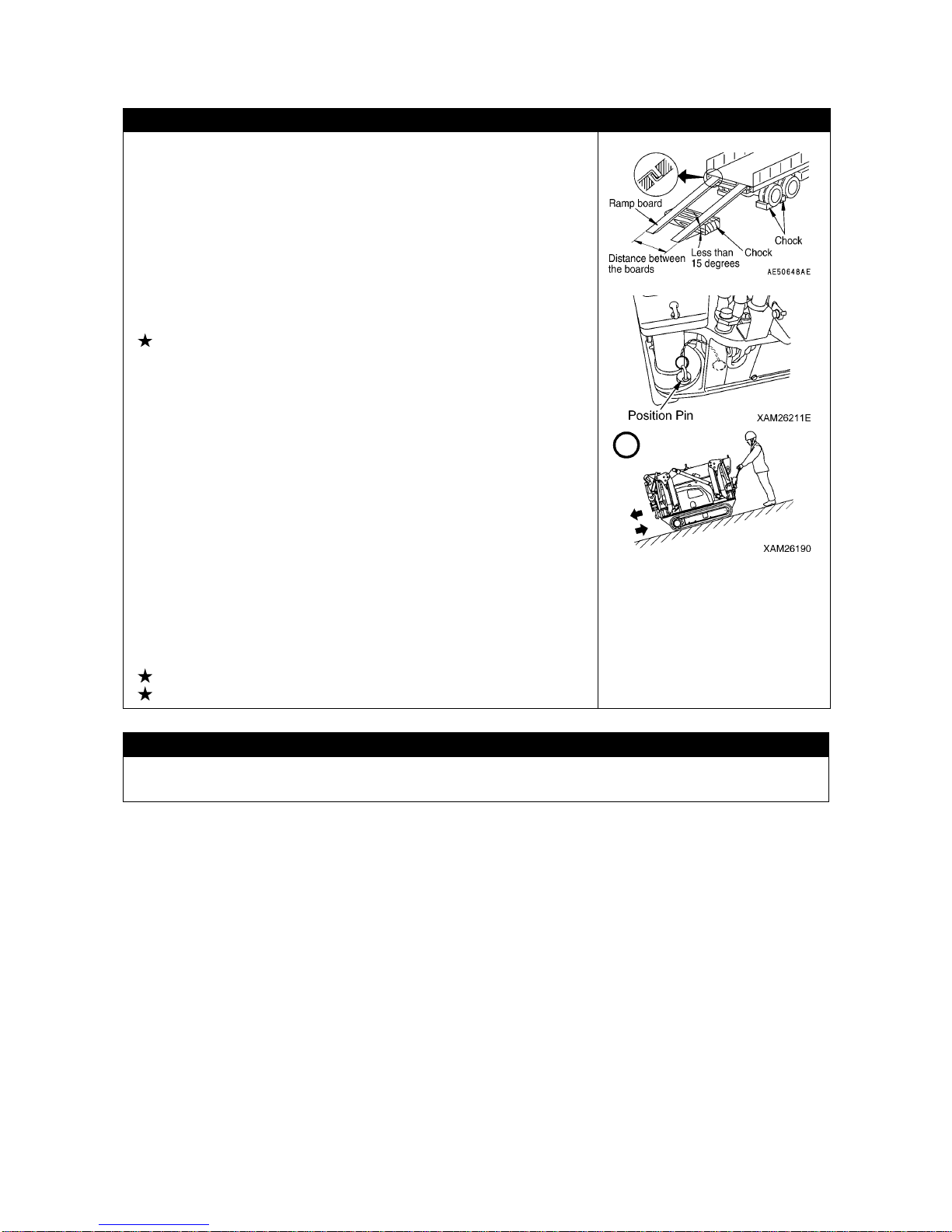
• Use ramps underneath with an angle less than 15 degrees. In
addition, decide the clearance between ramps to meet the center of
the rubber tracks.
• Always set the Machine in the "travelling position" and securely
insert the position pins (4 pieces) to the outrigger ro tary parts before
loading or unloading the Machine.
See “Operation 2.5 Machine Travel Position” for details.
• Always move backward when loading the Machine. Moving forward
may cause a trip.
• When loading or unloading, set the e ngine rotation to low idlin g (low
speed rotation) and operate slowly by low speed travels.
• Use ramps that have fully strong width, length and thickness, and
that enable safe loading/unloading.
Reinforce with blocks or other substances if the ramps move at all.
• Remove mud and other substances from the footing to prevent the
Machine from skidding over the ramps. Remove anyth ing stuck to
the ramps such as grease, oil or ice, and keep clean.
Be especially careful in the rain when slips can easily occur.
• Do not change direction over a ramp. Temporarily leave the ramp
before correcting the direction.
• Be slow when operating to change the direction on the truck
platform where the footing is unstable.
• After loading the Machine, apply the wood blocks so that the
Machine does not move, and securely fix with wire ropes or other
means.
See “Operation 5.1 Loading/unloading” for details.
See “Operation 5.3 Cautions in Loading Machine” for details.
CAUTIONS DURING TRANSPORT
Observe the related regulations and exercise safety during transport.

2-22
CAUTIONS WHEN LOADING/UNLOADING WITH A CRANE
Be careful of the following when loading or unloading the Ma chine by
hoisting with a crane.
• When lifting up the Machine, always set it to the stowage position
first, and lift from the lifting bracket (A) on the top of the boom.
Always use only this bracket and only one sling wire. Any other
manner than this, i.e. from other lifting brackets or multiple sling
wires, may cause droppage of the machine and result in serious
injury or death.
Where there is no choice but the machine has to be hoisted in a
different manner, please contact us or service agencies.
• Only use sling utensils (e.g. wire ropes and shackles) which are
proved to be capable to the mass (weight) of the machine.
• The crane’s stowed posture when it is hoisted means its "travelling
position" where 4 of outrigger position pins are securely inserted in
the outrigger rotary.
The center of the balance of the machine is specified subject to that
the machine is in its travelling position. In addition, to set it into that
position correctly, secure the hook block (4) to its stowing position,
as well as stretch the wire rope tight which aid to prevent the boom
derricking cylinder form extending.
See “Operation 2.5 Machine Travel Position” for details.
• When the machine is hoisted in such manner for an extensive time ,
the boom derricking cylinder may extend which causes the center of
the balance of the machine to change and put it out of balance.
Thus, hoisting should be limited to within 10 minutes.
• Where it is required to hoist the machine for a longer time
(exceeding10 minutes), or when it is carried by a helicopter, use a
proper carriage deck as shown in the diagram on the right, for safe
transportation.
Recommended hoisting equipment
• Shackle: BC or SC, nominal 14

2-23
4. BATTERY HANDLING PRECAUTIONS
BATTERY HANDLING PRECAUTIONS
The battery fluid includes diluted sulfuric acid, and generates
hydrogen gas, and causes bodily accidents and fires if handle
improperly, so always observe the followings.
• Do not let a cigarette or any fire source approach the battery.
• Always put on protective glasse s and rubber gloves before han dling
the battery.
• If the battery fluid has contacted clothing or skin, immediately wash
away with a large quantity of water.
• If the battery fluid entered an eye, wa sh immediat ely with wa ter and
see the doctor as soon as possible.
• If you have swallowed the battery fluid by mistake, immediately
drink a large quantity of water, milk, raw egg or vegetable oil, and
see the doctor as soon as possible.
• Wipe with a wet clean cloth when cleaning the battery upper surface
or related part. Do not use organic solvent or detergent for instance
gasoline or paint thinner.
• Tighten the battery cap fully.
• If the battery fluid is fro zen, do not charge battery or start the engine
using other power source. Such act may cause the battery to catch
fire.
• Before charging or starting up using other power source, defreeze
the battery fluid and check that failur e s such as battery fluid leak do
not exist.
• Always detach the battery from the Machine frame before charging
the battery.
PRECAUTIONS WHEN STARTING UP USING BOOSTER CABLE
Wrong booster cable connection method may result in fire , so always
observe the following.
• Start the engine with two people, with one standing on the driving
operation position in the travel operation panel side.
• When starting using other Machine, be careful to prevent contact
between the normal Machine and broken Machine.
• Keep the starter switch key of both the normal Machine and the
broken Machine in OFF position when the booster cable is
connected.
• Do not connect to wrong side [connecting (+) to (-), (-) to (+)] when
connecting the booster cable.
• Start connecting from (+) terminal first, but start disconnecting from
(-) terminal (ground) first.
• Connect the ground to the (-) terminal of the battery of the broken
Machine when connecting the ground as the last procedure.
See “Operation 8.4 Starting Engine with Booster Cable” for
details.
• Avoid the contact between clips of the booster cable, and contact
between a clip and the Machine when disconnecting the booster
cable.

2-24
PRECAUTIONS WHEN CHARGING THE BATTERY
Improper handling when charging the battery may cause the battery
to explode. Follow the manuals attached to the Machine and the
charger, and always observe the followings.
See “Operation 8.3 Ca utions in Charging the Battery” for details.
• Carry the charger to a location with good ventilation, then remove
the battery cap. Doing so causes the hydrogen gas to disperse and
prevents explosion.
• Adjust the charger voltage to suit the voltage of the battery to
charge. Mistake in adjusting the voltage may cause explosions due
to overheat and ignition of the charger.
• Sec urely fix the (+) charge clip of the charger to the (+) terminal of
the battery, then securely fix the (-) charge clip to (-) terminal of the
battery.
• Set the charge current to no more than 1 /10 of th e rated capa city of
the battery, or, in case of quick charge, set to the rated capacity of
the battery or smaller.
• Excessive charge current may cause leap fire and explosion
caused by fluid leak or fluid deficiency.

2-25
5. MAINTENANCE PRECAUTIONS
5.1 PRECAUTIONS BEFORE MAINTENANCE
FAILURE REPORT
Execution of maintenance not described in our manual may cause unexpected failures.
Ask us or our sales service agency for repair.
CLEAN BEFORE INSPECTION OR MAINTENANCE
• Before starting an inspection or maintenance, clean the Machine
and prevent rubbish from entering the Machine to ensure safety
during maintenance.
• Attempting inspection or maintenance with the Machine still dir ty not
only lessens chance of locating faulty part, but may cau se rubbish or
mud to get into your eyes, or slipping and tripping that results in
injury.
• Always observe followings when washing the vehicle.
• Use antislip shoes to prevent slips and tr ips caused by it being wet
underfoot.
• Put on protective equ ipment when using a high pressure steam car
wash. Avoid the accidents that the contact with high pressure
water causes the skin lac eration or mu d or other subst ance flying
into eye.
• Do not spray water directly onto the electrical system (sensors,
connector (1), receiving box and related). Any water in the
electrical system causes faulty operations and may trigger
improper operations, thus is dangerous.
TIDY UP THE WORKPLACE
In the workplace, put away the tools, hamme rs and other things that obstru ct the works, wipe off slippery
items such as greases and oils, and exercise tidy up and cleaning for safe work.
An untidy workplace may cause stumbles and slips that result in injury caused by tipping.
FOLLOW SUPERVISOR INSTRUCTION DURING TEAMWORK
Appoint a person who supervises the work and follow his/her instructions in case of Machine repair or
installing/uninstalling a work device.
Unexpected accidents due to mis-communication between workers may occur during teamwork.
USE APPROPRIATE TOOLS
Do not use damaged or deteriorated tools, or use a tool not intended
for the purpose. Use tools suitable for the maintenance work.
Entrance of a broken piece of a tool such as a boss with crashed
head or a hammer may destroy eyesight.
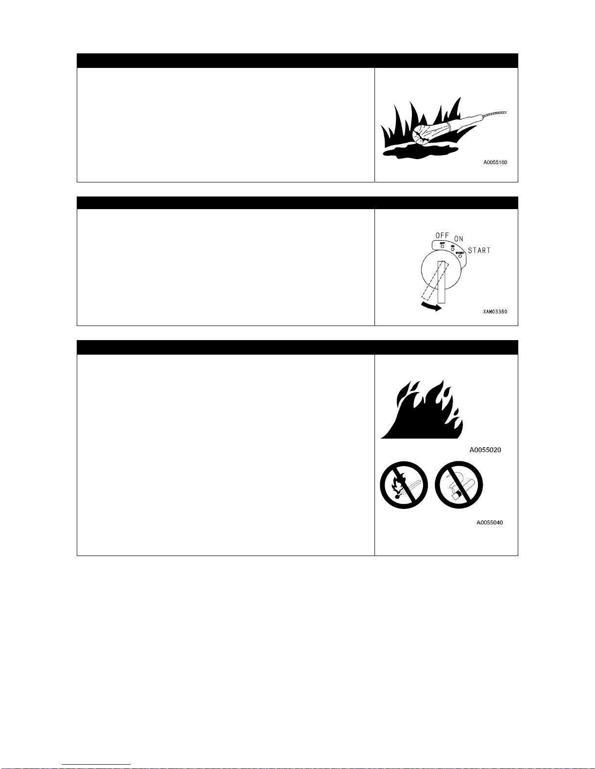
2-26
HANDLING ILLUMINATION DEVICES
• Use explosion-proof illumination devices when inspecting the fuel,
oil, battery fluid or similar substance. Failure to use an
explosion-proof illumination device may cause leap fire and
explosion.
• Attempting to work without using an illumination device in a dark
place may cause injury or ot her issue. Always use an illuminat ion
device.
Do not use a lighter or other burning object even if dark. Such use
may cause fire, and f urthe rmo re th e batt ery gas may c atc h fi re and
explode.
STOP ENGINE BEFORE INSPECTION OR MAINTENANCE
• Before inspection or maintenance, always park the Machine at a
location where the ground is level, rock-falls and landslides do not
occur, is a lowland and flood does not occur, and fully ret ract and
lower the boom, and stop the engine.
• Operate each of the crane operation levers forward backward
several times to relieve the pressure remaining in the hydraulic
circuits.
• Apply pawls to prevent rubber tracks from moving.
• People in charge of the maintenance should pay attention to
prevent body parts and clothes from contacting the moving parts.
FIRE RISK PREVENTION
Always observe the followings during maintenance where the fuel,
oil, battery or other substance that may catch fire are handled.
• Keep the fuel, oil and any other easily combustible oil and fats a way
from fire during storage.
• Do not leave the site when replenishing the fuel or oil.
• Use incombustible cleaning oil for the objects such as the
components, and do not use light petroleum, gasoline or anything
else that may catch fire.
• Do not smoke when inspecting or maintaining. Smoke at a location
designated to do so.
• When inspecting fuel, oil, battery fluid or similar, use
explosion-proof illumination devices but do not use fires such as a
lighter or a match for illumination.
• Loosened and damaged electrical connections may cause short
circuit that may result in a fire. Inspect accordingly during the
inspections before starting work.
• Make sure a fire extinguisher is in place near the inspection/
maintenance site.

2-27
5.2 PRECAUTIONS DURING MAINTENANCE
NO UNAUTHORIZED PEOPLE
Do not admit anyone other than necessary workers during maintenance. And post a guard as
necessary.
Be especially careful in case of a polishing, welding work, or digging work.
MEASURES UPON FINDING ABNORMALITY DURING INSPECTION
• Always repair whenever an abnormality is found during inspection.
Attempt to use without repairing the defect may cause bodily accidents.
• Ask us or our sales service agency for repair depending on the failure type.
DO NOT DROP TOOLS OR PARTS INSIDE THE MACHINE
• Do not drop any bolt, nut or tool inside the Ma chine when in specting while opening the in spection port
or tank replenishment port. Dropped objects may damage the Machine or cause the Machine to
operate improperly and thus may cause accidents. If dropped, always retrieve.
• Do not keep anything unnecessary for the inspection in your pocket.
NOISE CAUTION
Large noise in the surroundings may cause hearing difficulty or deafness.
Put on ear covers or earplugs before long time noise exposure for instance an engine maintenance.
WORK TO BE CARRIED OUT BY AT LEAST TWO PEOPLE DURING MAINTENANCE WITH
THE ENGINE RUNNING
To prevent accidents, do not attempt maintenance when the engine
is running.
Always observe the followings in case of main ta ining w ith the engine
running for unavoidable reason.
• One should be in an operable position by the travelling operation
unit of the machine and be ready to stop the engine whenever
necessary, and both should keep a good interaction, as well.
• Be es peci ally car eful when working ne ar a rot ating p art which m ay
become entangled.
• Do not touch operation levers. Before handling an operation lever
for unavoidable need, always give a sign to other person and let
him/her evacuate to a safe place.
PRECAUTIONS WHEN WORKING BELOW THE MACHINE
• Park the Machine over a level and fir m location, and fully retra ct and
lower the boom.
• Before the maintenance below the Machine, extend the outriggers
to the maximum so the Machine lifts. When doing so, insert support
platforms (height increasers) below front and rear of the Ma chin e to
stabilize the Machine.
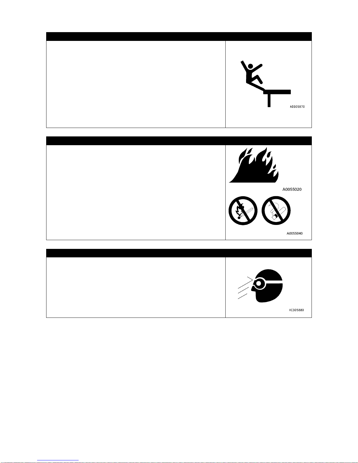
2-28
CAUTIONS WHEN WORKING ABOVE MACHINE
• Tidy the footing to avoid falling and always observe following
precautions during maintenance above the Machine.
• Do not spill oil or grease.
• Do not sprawl the tools.
• Beware of the footing when walking.
• Do not jump from the Machine under any circumstance.
Use a platform, and secure your body with three locations of the
limbs (both feet and one hand, or both hands and one foot) when
climbing up or down the Machine.
• Use protective equipment that suit the work.
• Do not step on the boom, outrigger or machinery cover to prevent
bodily accidents such as falling or tripping due to slippage.
CAUTIONS WHEN REPLENISHING FUEL OR OIL
The fuel, oils and similar substance may catch fire if a fire comes
near.
Gasoline is used as the fuel and thus r equire s extra effort to observe
the followings.
• Keep the engine stopped when supplying.
• Do not smoke when supplying.
• Immediately wipe away dripped fuel or oil.
• Securely tighten the fuel and oil caps.
• Supply fuel/oil at a location with good ventilation.
• Do not leave the site when replenishing the fuel or oil.
BEWARE OF CHIPS WHEN WORKING WITH HAMMER
During hammering works, keep protective equipment such as
protective glasses and a helmet on, and insert a copper bar or similar
object between the hammer and the target when hitting.
Giving impact to a hard metal part such as a pin or a bearing may
cause a broken chip to enter eye and inflict injury.

2-29
PRECAUTIONS DURING WELDING REPAIR
Weld in a location with good facilities, and, only authorized personnel are permitted to weld.
Unauthorized personnel are strictly prohibited since risks such as gas generation, fire and electrical
shock are present when welding.
The personnel authorized to weld are requested to always observe the followings.
• Disconnect the battery terminals to prevent battery explosions.
• Peel off the paint from the welding section to prevent gas generation.
• Attempting to heat up a hydraulic machinery, piping or a section near such part may cause
combustible vapor or mist to be generated and catch fire. Avoid heating such section.
• Directly heating a pressurized piping or rubber hose may cause a sudden snip. Apply a fire pro tection
cover.
• Disconnect the wiring connectors of the remo te cont rol devices, moment limiter display and converter.
• Put on protective equipment.
• Keep the ventilation well.
• Put away the combustibles and prepare a fire extinguisher.
• Do not ground to a location near electrical part. Such may cause the electrical part to malfunction.
DISCONNECTING THE BATTERY TERMINAL
Disconnect (-) terminal of the battery and stop the electrical flow
before repairing the electrical system or starting an electrical weld.
See “Operation 8. Battery Handling” for details.
CAUTIONS WHEN ADJUSTING RUBBER TRACK TENSION
• Grease is sealed inside the rubber track tension adjuster. The
grease is at a high pressure because of the tension of the rubber
track. Attempting to release the grease without observing the
following precautions may cause the grease valve to pop out and
result in a serious accident.
• Do not loosen the tension adjustment grease valve one full turn or
above. Doing so may cause the grease valve may pop out.
• To avoid the risk during tension adjustment, do not p lace your body
in right front of the grease valve.
See “Operation 2.1.3 [1] Checking/adjusting Rubber Track
Tension” for details.
HIGH PRESSURE HOSE HANDLING CAUTIONS
Oil leaking from high pressure hose may cause fire or bodily accident due to faulty operation.
Whenever a damaged hose or loosened bolt is found, abort working and ask us or our sales service
agency for a repair.
• Replacement of high pressure hose requires experienced skill. In addition, the tightening torques are
decided by the horse types and size.
Customers are prohibited to repair.
• Replace the applicable part if any of the following conditions is found.
• Hose sleeve damage or leak.
• Scratch or truncation of the coat, or exposure of reinforcing layer of a wire
• Coat is partially swollen.
• Indication of twist or collapse is at a movable part of hose.
• Alien object buried in coating.
• Hose sleeve deformation.
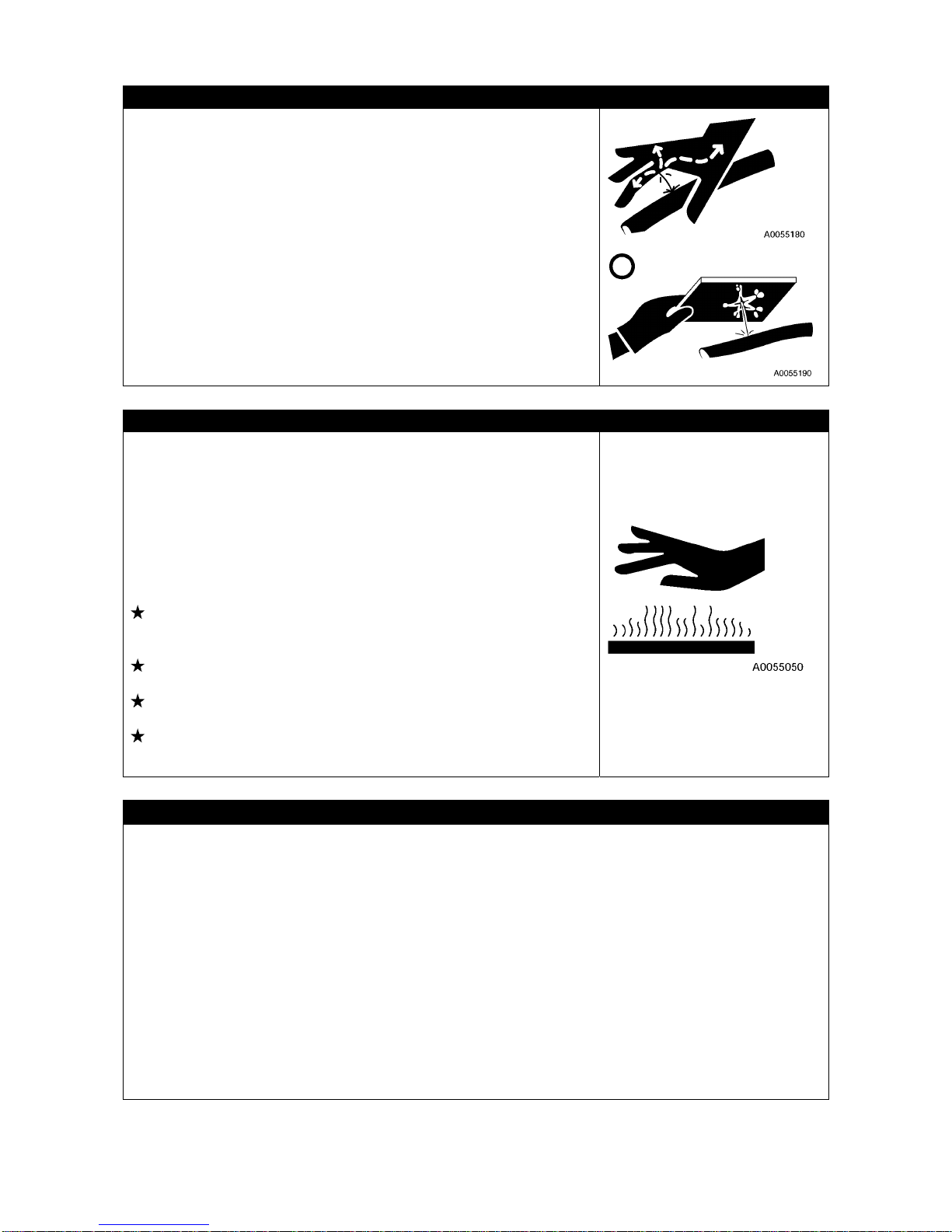
2-30
HIGH PRESSURE OIL CAUTIONS
Failure to make sure the pneuma tic circuit pressure is relieved be fore
inspection or replacement of a high pressure piping or hose may
result in bodily harm.
Always observe the followings.
• Do not start any inspection or replacement before the pressure
dissipates.
• Put on protective glasses and leather gloves.
• When a piping or hose leak exists, the piping/hose itself or vicin ity or
the ground is wet. If such is seen, a piping crack, hose crack or
inflation is considerable, so always ask us or our sales service
agency for a repair.
• High pressure oil leaking through a small hole may puncture the
skin or destroy eyesight upon contacting with skin or eye.
If the high pressure oil gave serious injury to skin or eye, wash away
with flowing water and see the doctor as soon as possible.
CAUTIONS WHEN TEMPERATURE IS HIGH
Parts such as the engine, all oils, exhaust system manifold and
muffler are at high temperature for a short time after stopping the
engine.
Attempting to remove the cap or carry out maintenance such as oil
draining, water draining or filter replacement may result in suffering
burns.
Wait until the temperature lowers, then execute the
inspection/maintenance following the procedure written in this
manual.
Operation 2.1.2 Checking Before engine starting: checking cooling
water level, checking oil level in engine oil pan, ch ecking oil level in
hydraulic oil tank.
Maintenance 8.7 50 hours maintenance: Replacement engine
lubrication oil and filter cartridge,
Maintenance 8.10 500 hours maintenance: Re placement hydrau-
lic oil return filter
Maintenance 8.11 1000 hours maintenance: Replacement oil
inside hydraulic oil tank
CHECKS AFTER INSPECTION/MAINTENANCE
Failure to execute an inspection/maintenance item or failure to check the function and operation of the
maintained part may cause an unexpected fault which may result in bodily accidents.
Always observe the followings.
• Checks with engine stopped
• Check for unexecuted inspection/maintenance.
• Check that inspection/maintenance was done without errors.
• Check for any dropped tool or part. Ones caught by the interior or lever related lin k mechanism poses
extra danger.
• Check for any fuel leak, water leak, oil leak, bolt loose and similar issues.
• Check with engine running
Be fully careful with safety when checking w ith the engine running wh ile referring to "Work to be carried
out by at least two people during maintenance with engine running" section.
• Check that the inspected/maintained part operates normally.
• Check that issues such as an oil leak do not occur when load is applied to the oil pressure by
increasing the engine rotation.

2-31
CAUTIONS WHEN TREATING WASTE
Always observe the following to prevent pollution environment of the
district inhabited with human or animal.
• Do not dispose the waste oil down a water system such as a sewer
or a river.
• Always drain into a container when draining the oil from the
Machine.
Do not directly drain to the ground.
• Observe the applicable legal regulations and rules when disposing
harmful substance such as the oil, fuel, solvent, filter or battery.

2-32
6. SAFETY LABEL LOCATIONS
Keep these labels clean all the time.
If lost, apply again or replace with new one.
Labels other than the following safety labels do exist, treat the same.

2-33
(1) Minimum hoist load (101-4602600) (2 places)
(2) Caution when hoisting machine (350-4589300)
(3) High temperature caution (349-4427800) (2 places) (4) Washing caution (350-4539700) (6 places)
(5) Engine rotation parts caution (553-4268600) (6) Warning (553-426800)

2-34
(7) Crane operating caution (101-2140500)
(8) High temperature caution (553-4267700) (9) No access to crane (349-4422000)
(10) Machine total weight (101-4588900) (11) Hook block caution (553-4267400) (2 places)

2-35
(12) Machine hoisting road (101-4594400) (13) Caution when travelling on slope (353-4488400)
(14) Total rated load chart (101-3314400)
Oo
(15) Caution for remote-control receiver (101-4593000) (16) Remote-control receiver error code chart
(101-4593100)
2-36
(17)Noise performance (101-4592900) (18) Caution for remote-control receiver plug
(300-4214000)
(19) Electric shock caution (553-4267300) (20) Caution for crane handling (349-4427100)
(21) Hydraulic oil caution (104-4550800)
(22) Main switch caution (349-4421400)
(23) Caution for over-hoist alarm (350-4432100)
2-37
(24) Slope caution (353-448600) (25) Fire ban (350-4433100)
(26) Winch caution (553-4267500)
(27) Caution when outrigger setting (353-4488700)
(4 places)
(28) Outrigger pin hole caution and footing check
(101-4593300) (4 places)
(29) Caution when driving, inspecting or maintaining
(893-4239100)
(30) Caution on emergency stop cancel (553-4266400)

2-38
(31) Precautions for use (portable card) (101-2141000)

2-39
7. WEEE DIRECTIVE LABEL LOCATIONS
Keep these labels clean all the time.
When replacing electrical equipment on which this label is affixed, always apply a new label.
[WEEE DERECTIVE LABEL (104-4549500)]
[LOCATIONS OF WEEE DIRECTIVE LABELS]
(1) Side of the relay box at the moment limiter
display backward
(2) Lower side of the moment limiter display
(3) Side of the moment limiter converter
(4) Side of the battery
(5) Top of the remote-controlled receiver
(6) Side of the inclination sensor
(7) Side of the boom length detector
(8) Side of the boom angle detector
(9) Side of the radio-controlled transmitter

2-40

3-1
OPERATION
1. MACHINE BY SECTION
3- 2
2. OPERATIONS
3-34
3. HANDLING RUBBER TRACKS
3-93
4. WHAT TO DO WITH TWISTED WINCH WIRE ROPE
3-97
5. TRANSPORTATION
3-98
6. HANDLING IN COLD WEATHER
3-101
7. LONG-TERM STORAGE
3-103
8. HANDLING THE BATTERY
3-104
9. TROUBLESHOOTING
3-109
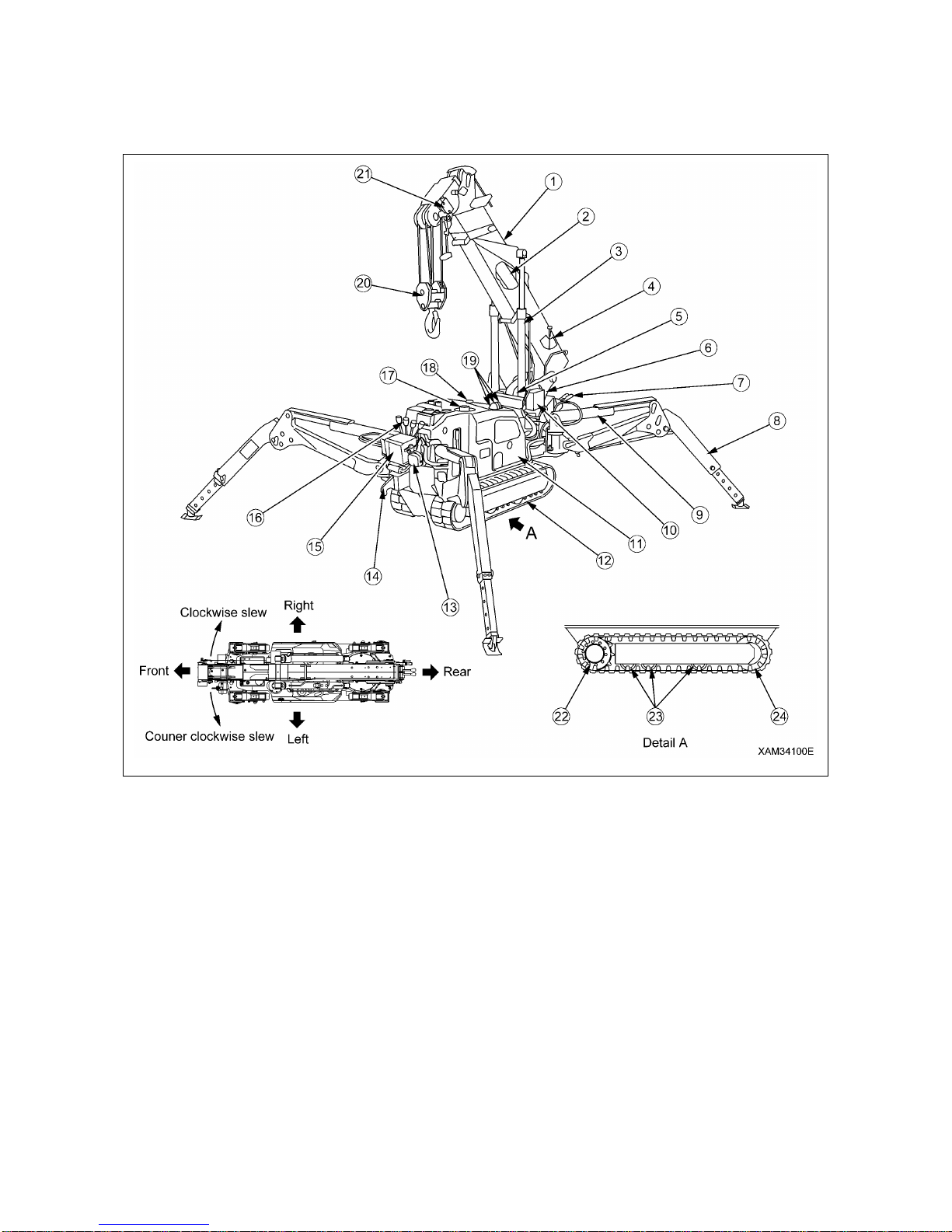
3-2
1. MACHINE BY SECTION
1.1 MACHINE BY UNIT
(1) Boom
(2) Boom telescoping cylinder (Inside the boom)
(3) Boom derricking cylinder
(4) Boom angle indicator
(5) Winch
(6) Post
(7) Travelling operation unit
(8) Outrigger
(9) Outrigger cylinder
(10) Moment limiter transducer
(11) Machinery cover Slewing device
(12) Rubber track
(13) Headlight
(14) Hook block hanger
(15) Moment limiter display unit
(16) Crane operation unit
(17) Hydraulic oil tank (Inside machinery cover)
(18) Fuel tank (Inside machinery cover)
(19) Working status lamp
(20) Hook block
(21) Over hoist detector
(22) Travelling motor and sprocket
(23) Track roller
(24) Idler

3-3
1.2 TRAVELLING OPERATION UNIT
(1) Left travelling lever
(2) Right travelling lever
(3) Grip
(4) Acceleration lever
(5) Engine emergency stop switch
(6) Travelling lever stand lock lever
(7) Travelling lever stand
(8) Horn switch
(9) Travelling high-speed switch
(10) Choke Knob
(11) Hour meter
(12) Fuse (15A)
(13) Fuse (15A)
(14) Fuse (30A)
(15) Battery charge lamp
(16) Headlight switch
(17) Main starter switch
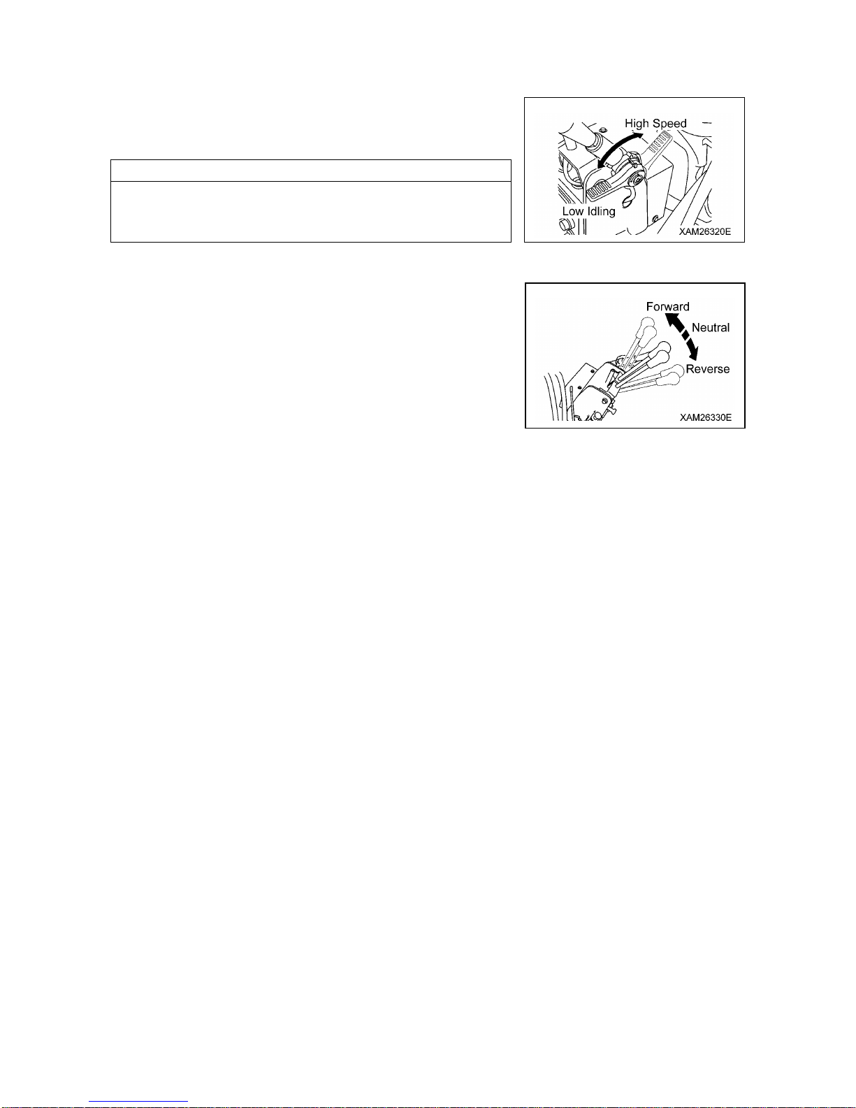
3-4
1.2.1 DESCRIPTION OF EACH LEVER
[1] ACCELERATION LEVER (4)
Use the lever to adjust the engine speed or output.
• Low idling:. Pull the lever toward you.
• High speed: Push the lever forward.
NOTES
• At the desired engine speed for your work, release the lever. It
will stop at that position.
• Acceleration lever is also provided on the crane operation unit.
[2] LEFT/RIGHT TRAVELLING LEVER (1), (2)
Use these levers to move the machine forward/backward, stop,
slew, and to adjust the travelling speed.
• Forward: Push the left and right levers forward at the same time.
• Neutral: Release your hands from left and right levers at the
same time. The levers return to the NEUTRAL position
and the machine automatically brakes and stops at that
position.
• Backward: Pull the left and right levers toward you at the same time.
• Left turn: Release your hand from the left lever and operate the right lever forward or backward.
• Right turn: Release your hand from the right lever and operate the left lever forward or backward.
• Spin turn: Operate the left and right levers to the opposite direction. The left and right crawlers turn to the
opposite direction, allowing you to make the spin turn.
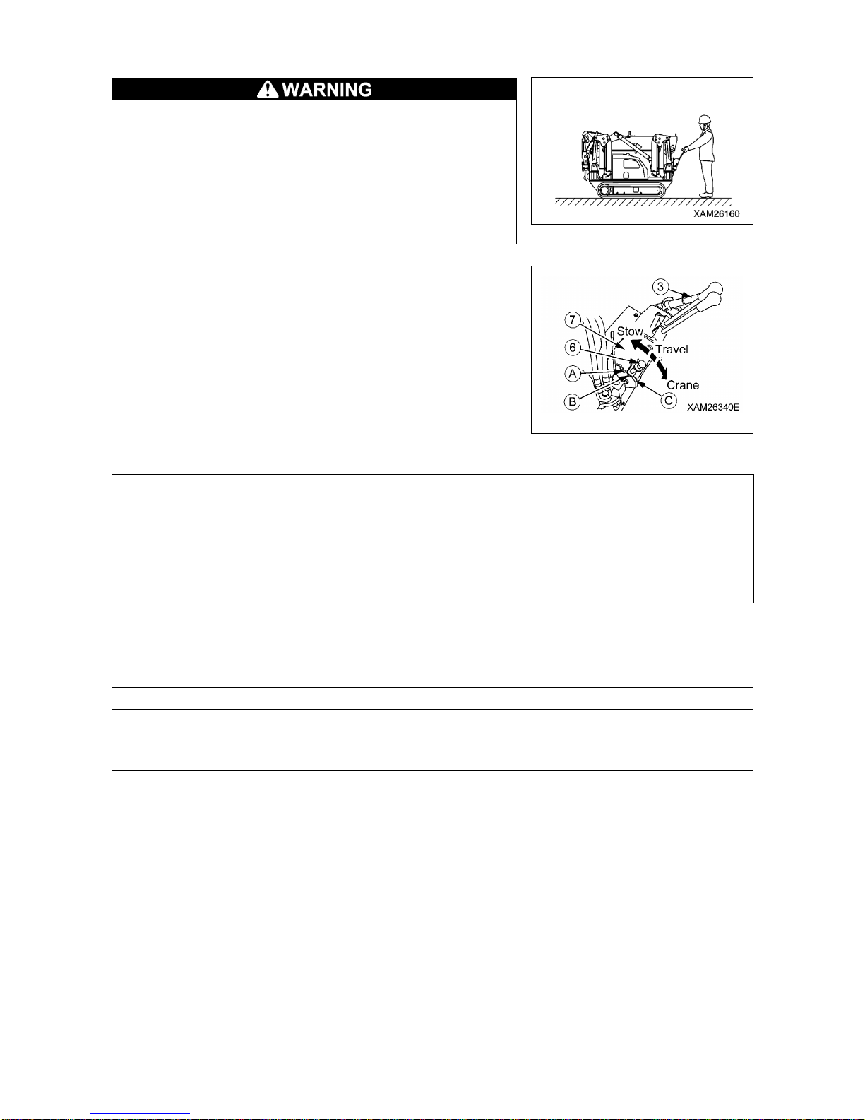
3-5
[3] TRAVELLING LEVER STAND (7) AND LOCK LEVER (6)
• Before setting the travelling lever stand to “Travelling
position”, be sure to stow the crane and let the machine
assume travelling position.
Travelling with the crane not in travelling position, may
cause it to tip over and cause a serious accident .
• When pulling up the travelling lever stand lock lever, be
careful not to contact the travelling lever, as it may cause
the undercarriage to move.
Use this stand to switch the work state of the machine (Travelling
control, Crane operation, Stowing position).
• Travel: Pull up the lock lever (6) before erecting the entire lever
stand (7) forward to the "Travelling Control Position". The
machine is in "Travelling Control Position" when the bottom end
of lock lever (6) fits into the guide groove (B).
• Crane: Pull up the lock lever (6) before pressing the whole lever
stand (7) down to the "Crane Operation Position". The machine is
in "Crane Operation Position" when the end of lock lever (6) fits
into the guide (C).
NOTES
• Where the travelling lever stand is set in the “Travelling position”, only travelling operation is available.
In such a condition, respective crane control levers and outrigger setting switchs are disabled to
manage their functions.
• Also, where the travelling lever stand is set in the “Travelling position”, any outrigger setting or crane
operations by the Remote Controller are not workable.
• For any outrigger setting or crane operations, set the travelling lever stand in the "Crane Position".
• Stow Position :Pull up the lock lever (6) and grab the Grip (3) to press the whole lever stand (7) down
to the "Stow Position". The machine is in "Stow Position" when the end of lock lever (6) fits into the guide
(A).
NOTES
When the travelling lever stand is set in the "Stow Position", the whole of the stand can be positioned
within the back end of the carrier. (Full length: 2000mm)
This position may be convenient du ring transportation or when the parking area is restricted.

3-6
1.2.2 DESCRIPTION OF EACH SWITCH
[1] STARTER SWITCH (17)
Use this switch to start and stop the engine.
• OFF : You can insert/remove the key at this position. All the
switches in the electrical system are turned off and the
engine stops.
• ON : Electricity runs into all the circuits.
• START: When the engine has started, release your finger from
the key. The key automatically returns to the ON position.
[2] CHOKE KNOB (10)
This knob is to be used when ambient temperature is low and
engine is difficult to start.
Use the choke in the following manner:
1. Pull the knob all the way back.
2. Place the starter switch at “START” position.
3. When the engine has started, press the knob to original position.
[3] HEADLIGHT SWITCH (16)
Use this switch to turn on the headlights on front of the machine.
• ON: Pull the switch toward you forward. The headlights turn on.
• OFF: Push the switch forward. The headlights turn off.
NOTES
The headlights do not light up even if the headlight switch is
operated when the starter switch is at the OFF position.
[4] HORN SWITCH (8)
Use this switch to honk the horn.
• Honking the horn: Press the switch.
NOTES
• The horn will stop when you release your finger from the
switch.
• The horn switch is provided on the crane operation side as well.

3-7
[5] TRAVELLING HIGH-SPEED SWITCH (9)
Use this switch to change the mode of the machine travelling
speed.
• ON: Push the switch forward. The travelling speed mode changes
to high-speed travelling mode.
• OFF: Push down the switch toward you. The travelling speed
mode changes to low-speed travelling mode.
NOTES
• In high-speed travelling mode, you may feel difficulty in changing travelling direction. In such event , it
is advisable to switch to low-speed travelling mode.
• During loading to or un-loading from a truck, use low-speed travelling mode since the footing of the
operator may become insecure.
• When travelling over uneven terrain, footing of the operator as well as the machine position may
become vulnerable. Switch to low-speed travelling mode in such conditions.
[6] ENGINE EMERGENCY STOP SWITCH (5)
Use this switch in case of an error in the machine to stop the
machine for emergency.
• ON: Press the switch. The engine stops.
• OFF: Turn the switch clockwise (direction of the arrow in the right
figure). The switch returns to the original position.
NOTES
When restarting the engine after emergency stop, be sure to turn
the engine emergency stop switch to the OFF position before
starting the engine.
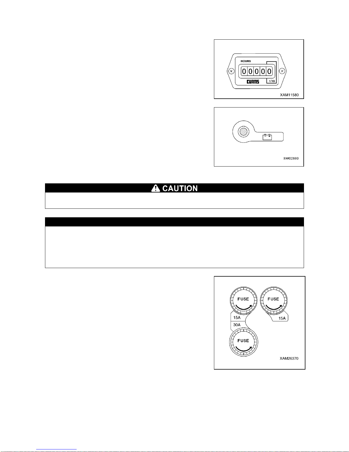
3-8
1.2.3 DESCRIPTION OF EACH METER AND LAMP
[1] HOUR METER (11)
This meter shows the total running hours of the machine.
Use this value as the reference for periodical check interval.
The value in the meter increases when the engine starts.
The value does not change in the condition where the engine stops,
though the starter switch is in ON position.
[2] BATTERY CHARGE MONITOR (15)
This monitor indicates errors in the battery charge system.
If it lights up when the starter switch is turned to the ON position
and goes off as the engine rotation increases after the engine is
started, the battery charge system is normal.
If it lights up during the operation, there is an error in the battery
charge system. Immediately stop the machine and check the
engine.
[3] FUSES (12), (13), (14)
Be sure to turn the starter switch to the OFF position when checking or replacing a fuse.
CAUTION
Fuses protect electrical components and wires from being burnt out.
• Fuses are tubular fuses. If a fuse was corroded and shows white powder, be sure to change
the fuse.
• If a fuse has melt down, always check the cause in the circuit and repair the problem before
changing the fuse.
• Always use a fuse of the same capacity when replacing one.
Systems and capacities of fuses are as follows:
• Fuse (12) (15A): For remote control system, emergency stop
system, engine control system, horn switch, travelling high-speed
switch、and moment limiter.
• Fuse (13) (15A): For lamps, horn and crane inclination alarm
system.
• Fuse (14) (30A): For starter motor, and power source.
1. Turn the fuse holder on control panel counterclockwise and take
it out.
2. Check and replace fuses contained in the removed fuse holder.
3. Install new or checked fuse to the holder and turn it clockwise to
tighten.

3-9
1.3 CRANE OPERATION UNIT
(1) Slewing lever
(2) Boom telescoping lever
(3) Winch lever
(4) Boom derricking lever
(5) Acceleration lever
(6) Headlight
(7) Moment limiter display panel
(8) Over hoist and moment limiter alarm buzzer
(9) Emergency stop cancel switch
(10) Boom stowing switch
(11) Level
(12) Working status lamps
(13) Engine emergency stop switch
(14) Auxiliary starter switch
(15) Hook stowing switch
(16) Horn switch
(17) Outrigger individual setting switch
(a) Outrigger (1) setting switch
(b) Outrigger (2) setting switch
(c) Outrigger (3) setting switch
(d) Outrigger (4) setting switch
(18) Outrigger collective setting switch

3-10
1.3.1 DESCRIPTION OF EACH LEVER
[1] ACCELERATION LEVER (5)
Use the lever to adjust the engine speed or output.
• Low idling: Turn the lever to counter clockwise.
• Full speed: Turn the lever to clockwise.
NOTES
• At the desired engine speed for your work, release the lever. It
will stop at that position.
• Acceleration lever is also provided on the travelling control unit.
[2] SLEWING LEVER (1)
Use the lever to slew the crane boom and post.
• Slew counter clockwise: Push the lever forward (Left).
• Neutral: Release your hand from the lever.
The lever returns to the NEUTRAL position and the
slewing stops.
• Slew clockwise: Pull the lever toward you (Right).
[3] BOOM TELESCOPING LEVER (2)
Use this lever for telescoping the crane boom.
• Extend: Push the lever forward (Extend).
• Neutral: Release your hand from the lever.
The lever returns to the NEUTRAL position and the boom
telescoping stops.
• Retract: Pull the lever toward you (Retract).
[4] WINCH LEVER (3)
Use this lever to raise/lower the hook block of the crane.
• Lower: Push the lever forward (Down).
• Neutral: Release your hand from the lever.
The lever returns to the NEUTRAL position and the
machine automatically brakes. The lowering/raising of the
hook block stops.
• Raise: Pull the lever toward you (Up).
[5] BOOM DERRICKING LEVER (4)
Use this lever for derricking the crane boom.
• Lower: Push the lever forward (Lower).
• Neutral: Release your hand from the lever.
The lever returns to the NEUTRAL position and the boom
derricking stops.
• Raise: Pull the lever toward you (Raise).

3-11
1.3.2 DESCRIPTION OF EACH SWITCH
[1] EMERGENCY STOP CANCEL SWITCH (9)
• Do not turn the emergency stop cancel switch to the ON (cancel) position except in a machine
failure condition or when conducting a load test. When the emergency stop cancel switch is in
ON position, the moment limiter functions are not available. Any crane operation in such
conditions will result in dropping of hoisted load, breakage of crane boom, and/or crane
tipping due to over load, and may cause a serious accident resulting in death or serious injury.
Key for the switch must be detached during normal operations.
• Do not turn the emergency stop cancel switch to the ON (cancel) position when stowing the
hook.
The winch wire rope may be cut causing the hook to fall on or damage the boom.
Use the hook stowing switch when stowing the hook.
Use the emergency stop cancel switch only for the purpose to
release emergency stop when the safety device of the Crane
seems to have a failure, or when a load test is required.
Open the cover when using the switch.
• ON (Clear): Insert the key into the switch. Turn the key clockwise
and retain the key at that position. The activation
stop function is cleared while the key is maintained at
the ON position.
• OFF (Auto): Insert the key into the switch and turn the key
counterclockwise. The activation stop functions.
The key can be removed or inserted at this position.
[2] BOOM STOWING SWITCH (10)
• The boom stowing switch cancels the auto-stop function of the lower-limit detecting interlock
device during the boom “lowering” operation.
Operate the boom derricking lever carefully when stowing the boom. Pay sufficient attention
not to let the boom collide with the machine body.
• Use the boom stowing switch only when stowing the boom.
Use this switch to stow the boom.
• ON: Keep pushing the switch downward and operate the boom
derricking lever to “LOWER” side. The boom lowers and
can be stowed.
• OFF: Release your finger from the switch. The switch returns to
the original position and the auto-stop function of the
lower-limit detecting interlock device will be activated.
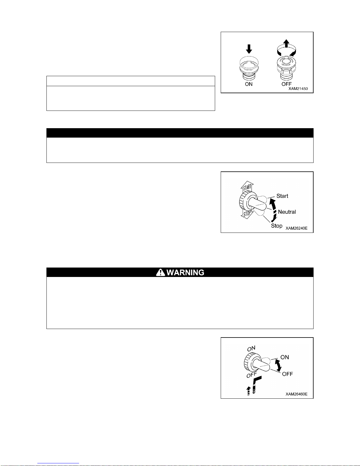
3-12
[3] ENGINE EMERGENCY STOP SWITCH (13)
Use this switch in case of an error in the machine to stop the
machine for emergency.
• ON: Press the switch. The engine stops.
• OFF: Turn the switch clockwise (direction of the arrow in the right
figure). The switch returns to the original position.
NOTES
When restarting the engine after emergency stop, be sure to turn
the engine emergency stop switch to the OFF position before
starting the engine.
[4] AUXILIARY STARTER SWITCH (14)
CAUTION
The auxiliary starter switch functions only while main starter switch at travel control is in ON
position. To start-up engine using the auxiliary starter switch, the main starter switch must
remain at ON position.
Use this switch to start and stop the engine.
• START: Keep pushing the switch upward. The engine starts.
When the engine has started, release your finger from the
switch.
• Neutral: Release your finger from the switch. The switch returns
to the NEUTRAL position.
• STOP: Keep pushing the switch downward. The engine stops.
When the engine has stopped, release your finger from
the switch.
[5] HOOK STOWING SWITCH (15)
• The hook stowing switch cancels the auto-stop function of the over hoist detector.
Operate the winch lever carefully when stowing the hook block. Pay sufficient attention not to
let the hook block collide with the boom.
• Use this switch only when stowing the hook block.
• When the hook block is stowed in the hook block holder and the wire rope slacking is
eliminated, turn OFF the hook stowing switch without delay. Otherwise, the wire rope will be
over-wound which causes it to wedge into the winch drum.
Use this switch to stow the hook block at the lower top of the
machine.
• ON: Keep pushing the switch upward. The over hoist detector is
released and the hook block is wound up slower than the
normal operation mode, so that it is stowed in the hook
holder.
• OFF: Release your finger from the switch. The switch returns to
the original position and the auto-stop function of the over
hoist detector will be activated.
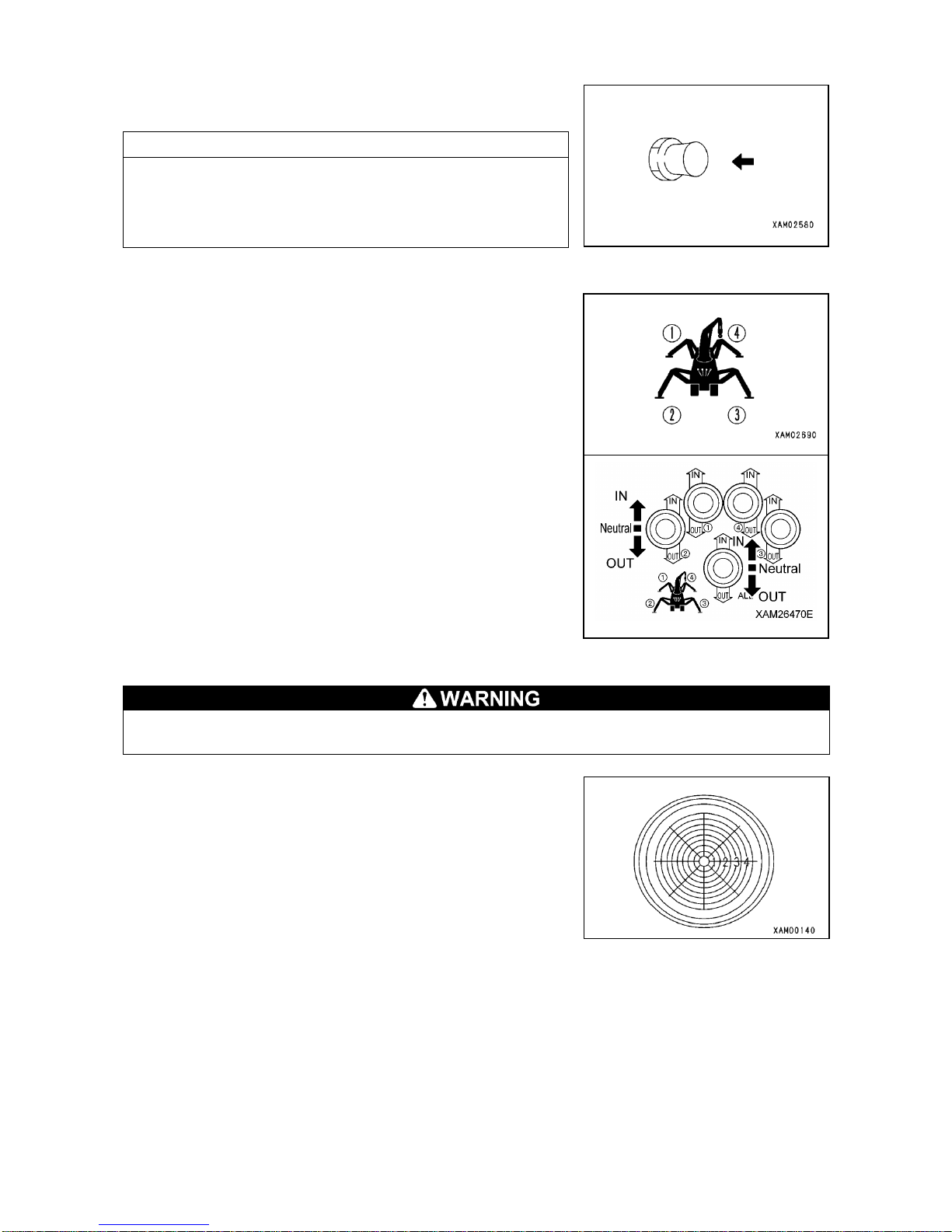
3-13
[6] HORN SWITCH (16)
Use this switch to honk the horn.
• Honking the horn: Press the switch.
NOTES
• The horn will stop when you release your finger from the
switch.
• The horn switch is provided on the travelling control side as
well.
[7] OUTRIGGER SETTING SWITCH (17), (18)
Use these switches to install or stow each of 4 [(1) to (4)]
outriggers.
Outrigger setting switch includes 4 Outrigger individual setting
switches (17) and 1 Outrigger collective setting switch (18).
4 Outrigger individual setting switches enable to control each of 4
[(1) to (4)] outriggers separately.
In contrast, the Outrigger collective setting switch enables to
control all the 4 [(1) to (4)] outriggers simultaneously.
• IN : Turn the switch upward.
Outrigger cylinder retracts and the outrigger is stowed.
• Neutral: Release your finger from the switch.
The swtich returns to its NEUTRAL postion and
extending or retracting of the outrigger is interrupted.
• OUT : Turn the switch downward.
Outrigger cylinder extends and the outrigger is installed.
[8] LEVEL (11)
When installing the outrigger, make adjustments while looking at the level so that the machine
body will be leveled. Performing the crane operation with the body tilted will cause overturning.
This device indicates how much the machine body is tilted.
The bubble position shows how much the machine is tilted in
which direction.
Use this device to verify that the machine is leveled when setting
the outriggers.

3-14
[9] WORKING STATUS LAMPS (12)
Color of each working status lamp shows current load factor (ratio
of the hoisting load weight to rated total load).
• Red lamp (12A) shows LIMIT WARNING where the load factor is
100 % or higher than the rated total load, when it is lit.
• Yellow lamp (12B) shows PRE-WARNING where the load factor
is 90 to less than 100 % of the “rated total load, when it is lit.
• Green lamp (12C) shows SAFETY ZONE where the load factor is
less than 90 % of the rated total load, when it is lit.
12A: Red lamp 12B: Yellow lamp
12C: Green lamp

3-15
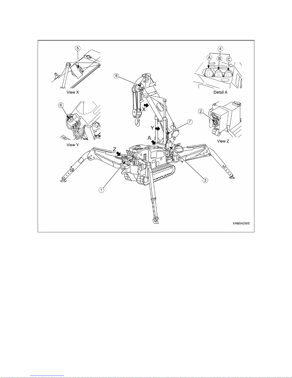
3-16
1.4 MOMENT LIMITER (OVERLOAD DETECTOR)
1.4.1 MOMENT LIMITER CONFIGURATION
(1) Moment limiter display unit
(2) Emergency stop cancel switch
(3) Moment limiter converter
(4) Working status lamp
(A) Red working status lamp (Warning lamp for
load factor of 100% or more)
(B) Yellow working status lamp (Pre-warning
lamp for load factor of 90 to 100%)
(C) Green working status lamp (Working lamp
for load factor of less than 90 %)
(5) Boom length sensor (right side of boom)
(6) Boom angle sensor (right side of boom edge)
(7) Pressure sensor (derricking cylinder) (two)
(8) Overwind alarm detector (left side of boom top)
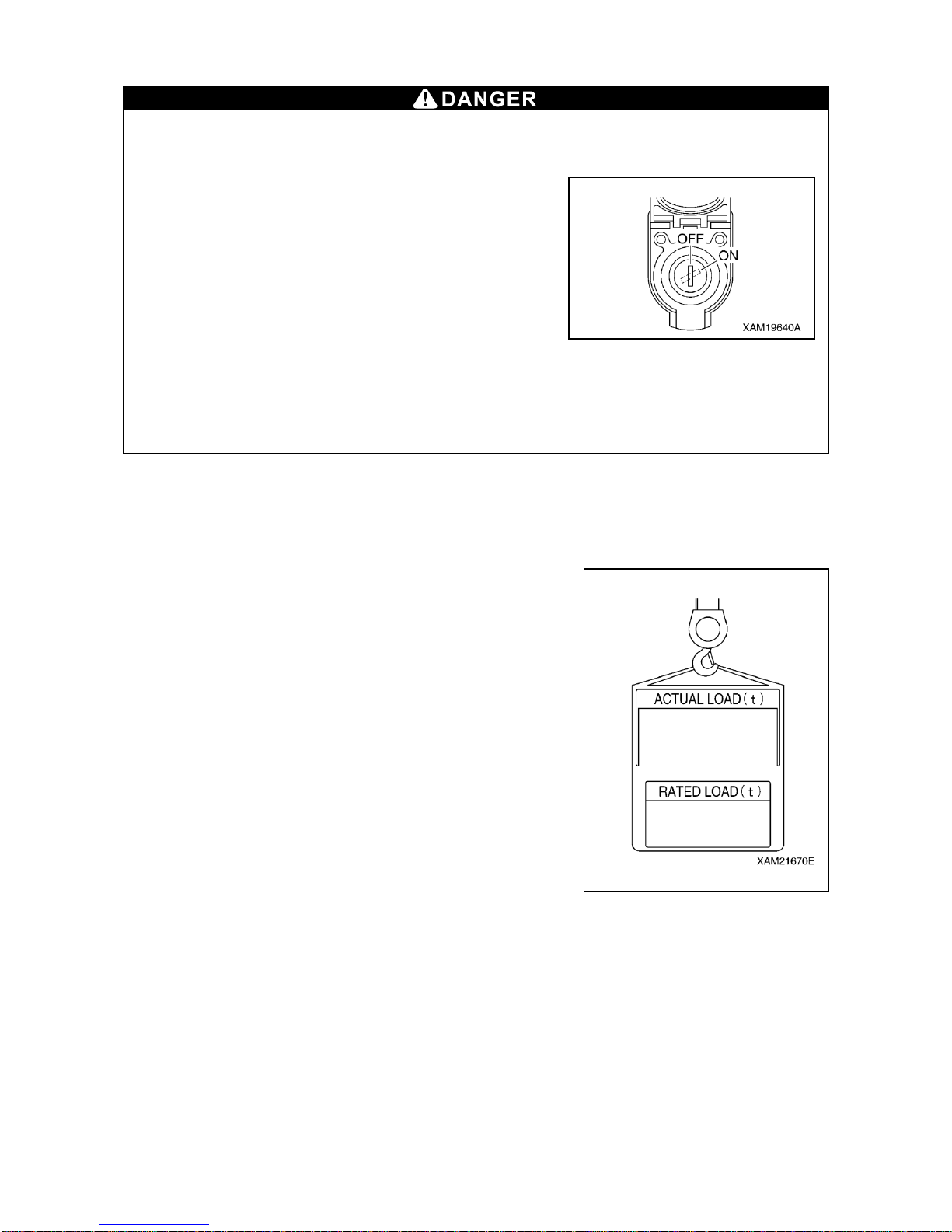
3-17
1.4.2 FUNCTION OF MOMENT LIMITER
• Do not remove, disassemble, or repair detectors. Do not move the detectors to another
location from original position.
• Should an object hit a detector or you find any damage on a detector, be sure to verify the
actuation status of the auto stop.
If you find any abnormality with the actuation of the auto
stop, do not fail to fix it.
• Do not turn ON (cancel) the emergency stop cancel
switch unless you find an error or check/perform
maintenance on detectors.
Overloading can cause the hoisted load to fall, boom
breakage, or overturning of this machine that can lead to
serious accidents resulting in death or serious injury.
• The machine will not stop automatically even if the crane
is overloaded during the crane slewing operation.
Do not slew the crane when being overloaded.
• When the boom approaches the stop position during the operation, be sure to change the
operation speed of the boom to low speed.
With high-speed boom operation, the boom may overrun the specified stop position, causing
serious accidents such as overturning of the machine resulting in death or serious injury.
The moment limiter is a device installed to prevent the hoisted load from falling, the boom from breaking,
or the machine from overturning due to overloading.
Always check the operation of the moment limiter before crane operation to verify no abnormality.
[1] MECHANISM OF MOMENT LIMITER
The moment limiter calculates current "rated total load" by knowing
the current boom position by the boom angle sensor and the boom
length sensor, by knowing the outrigger extension condition by the
outrigger position switch, and by knowing the number of wire falls
(entered by the operator).
Then by actually hoisting a load, the "read load" (hoist load) is sent
from the pressure sensor of the derricking cylinder to the moment
limiter.
The moment limiter comparatively calculates between the "rated
total load" computed out of the current position and the "actual
load" (hoisted load), and issues an alarm if the result indicates the
real load/rated total load=90 to 100%.
If the calculation result indicates the actual load/rated total
load=above 100%, an alarm is issued and the causes the boom
operation to automatically stop.
[2] DISPLAY OF THE MOMENT LIMITER ERROR MESSAGES
The moment limiter performs self-diagnosis on the moment limiter display unit when an error is issued by
the boom angle sensor, boom length sensor, pressure sensor, or when a circuit is opened or a connector
is disconnected.
The result is displayed on the “Rated Total Load Display” of the moment limiter display unit by an error
code to notify the operator of the error.
Immediately stop the use of the crane when an error code is displayed.
See “Operation 1.4.9 Moment Limiter Error Causes and Actions to be Taken”.

3-18
1.4.3 MOMENT LIMITER OPERATIONS
The moment limiter is a device for unexpected events. Do not rely solely on the device to avoid danger.
Pay sufficient attention during the operation not to cause auto-stop of the crane.
[1] PROHIBITED ACTIONS AFTER AUTO STOP
The following crane operations are prohibited after the crane has stopped automatically due to
overloading. These operations may cause overturning of the machine or breakage of the boom
and are very dangerous.
• Boom lowering operation • Boom extending operation • Hook raising operation
• Crane slewing operation
[2] MOMENT LIMITER OPERATIONS
Be sure to switch the engine speed to low speed and perform crane operation carefully if the
moment limiter load factor is 90% or higher.
Performing crane operation at high engine speed will swing the hoisted load and is very
dangerous, causing overloading and it may break the boom.
1. Safety Zone (With load factor of “less than 90%”)
When the hoisting load is less than 90% of the rated total load, the
working status lamp lights in green, indicating normal operation
status.
2. Pre-Warning (With load factor of “90 to less than 100%”)
When the hoisting load reaches 90% of the rated total load
(pre-warning), the working status lamp changes from green to
yellow and the alarm sounds intermittently, notifying the operator
and those around that the hoisting load is close to the rated total
load.
3. Limit Warning (With load factor of “100% or higher”)
When the hoisting load reaches 100% of the rated total load by
continuing the crane operation after exceeding 90% of the rated
total load (pre-warning), the working status lamp changes from
yellow to red and the alarm now sounds continuously. The
following crane operations will stop automatically.
• Hook raising operation • Boom extending operation
• Boom lowering operation
The LED of “100%” on the moment limiter load factor display lights
up.
Green lamp light up
Yellow lamp light up
Red lamp light up
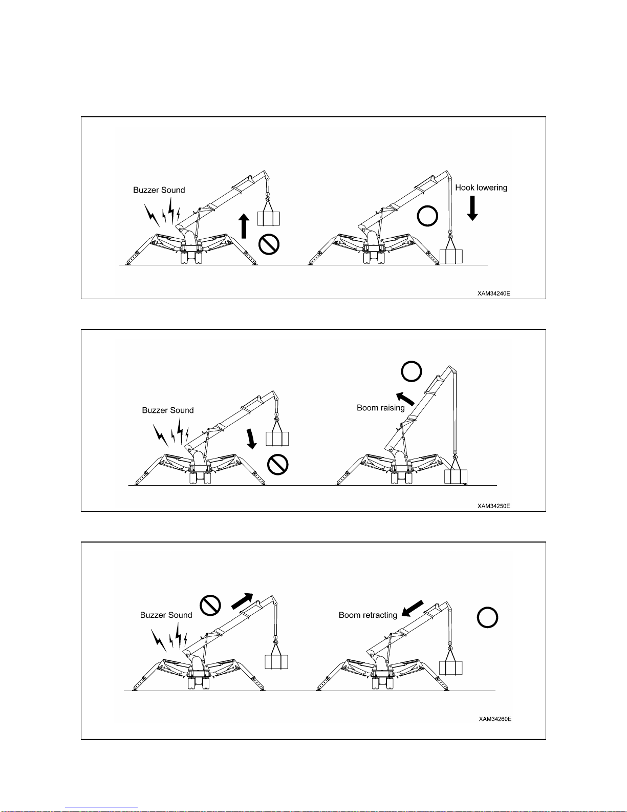
3-19
4. Recovery Operation from Auto Stop
The recovery operation from overloading should be the reverse operation of the crane operation that
caused the auto stop. Perform one of the followings.
(1) Lower the hook and put down the hoisted load on the ground.
(2) Raise the boom. Lower the hook so that the hoisted load will be as low as possible.
(3) Retract the boom.

3-20
1.4.4 NAMES OF MOMENT LIMITER DISPLAY UNIT
(1) Boom angle display
(2) Lifting height display
(3) Boom length display
(4) Boom lifting height upper limit LED (Red)
(5) Boom lifting height upper limit switch
(6) Boom angle lower limit LED (Red)
(7) Boom angle lower limit switch
(8) Over hoist detection LED (Red)
(9) Actual load display
(10) Rated total load display
(11) Working radius upper limit LED (Red)
(12) Working radius upper limit switch
(13) Working radius display
(14) Boom angle upper limit LED (Red)
(15) Boom angle upper limit switch
(16) Outrigger MIN. extension LED (Orange)
(17) Outrigger MID. extension LED (Orange)
Not in use MC-174C.
(18) Outrigger MAX. extension LED (Orange)
(19) Check switch
(20) Cancel switch
(21) Load capacity less than 70% LED (Orange)
(22) Load capacity 70 to less than 100% LED
(Orange)
(23) Load capacity 100% or more LED (Orange)
(24) 1-fall fall LED (Orange)
(25) 2-falls fall LED (Orange)
(26) 4-falls fall LED (Orange)
(27) Fall mode selector switch

3-21
[1] DESCRIPTIONS OF SWITCHES ON MOMENT LIMITER DISPLAY UNIT
1. WIRE FALLS SELECTOR SWITCH AND WIRE FALLS DISPLAY LED (ORANGE)
• When entering the number of wire falls, verify the actual used number of wire falls and make
sure to set up correctly.
Entering incorrect number of wire falls may prevent pre-warnings and boom auto-stop even
when the overload is being approched, and thus may result in crane damage or machine trip
that may result in serious accidents.
• Stop the crane operation when changing the number of wire falls using the number of wire
falls selector switch.
Changing the number of wire falls during the crane operation can cause unexpected
accidents.
• Perform the crane operation always after matching the number of wire falls displayed on the
moment limiter and the actual number of wire falls. Mistaking the number of wire falls causes
serious accidents.
The wire rope has the safe load per rope fall determined.
Determine the number of wire falls according to the maximum load to be hoisted.
With this machine, the hook for four wire fall of rope is referred to as the standard specifications.
The last status of the set number of wire falls is memorized even if the starter switch is turned to the OFF
position.
Use this switch to change the number of wire falls.
• Keep pressing the switch for 2 seconds or more.
The setting changes from “4-falls” to “1-fall”.
At the same time, the wire falls display LED changes from “4-falls”
to “1-fall”, indicating that the setting has changed.
• Then each time you press the switch for 2 seconds or more, the
setting of the wire falls changes from “1-fall” to “2-falls”, and then
from “2-falls” to “4-falls”.
NOTES
When changing the setting, right after doing so, release your
finger from the switch, and then press the switch again.

3-22
2. BOOM ANGLE UPPER LIMIT SWITCH AND LED (RED)
Use this switch to set or cancel the boom angle upper limit.
[SETUP]
With no upper limit value being set, set the boom to the angle you
would like, and press the switch for 2 seconds.
The boom angle at this point is set as the upper limit.
At the same time, the LED lights up indicating that the upper limit
value was set.
To enable this setting, turn the key switch to the ON position again
after turning it to the OFF position, or lower the boom by “10
degrees” or more from the set boom angle to get out of the
pre-warning zone while the engine is being started.
NOTES
Be sure to verify that the boom automatically stops at the set angle before performing the actual
operation. If the boom does not stop automatically, re-set the boom angle using the procedure above.
When the boom reaches the pre-warning zone or stops at the upper limit with the boom angle upper limit
set, the boom angle upper limit LED flashes.
[CANCEL]
With the upper limit value being set (LED ON), press the switch for 5 seconds.
The current upper limit value setting will be cleared. At the same time, the LED goes off indicating that the
upper limit value setting is cleared.
NOTES
The setting and canceling will not repeat even if you keep the switch pressed for more than 2 seconds.
Let your finger go off the switch and press the switch again.

3-23
3. BOOM ANGLE LOWER LIMIT SWITCH AND LED (RED)
Use this switch to set or cancel the boom angle lower limit.
[SETUP]
With no lower limit value being set, set the boom to the angle you
would like, and press the switch for 2 seconds.
The boom angle at this point is set as the lower limit.
At the same time, the LED lights up indicating that the lower limit
value was set.
To enable this setting, turn the key switch to the ON position again after turning it to the OFF position, or
raise the boom by “7 degrees” or more from the set boom angle to get out of the pre-warning zone while
the engine is being started.
NOTES
Be sure to verify that the boom automatically stops at the set angle before performing the actual
operation. If the boom does not stop automatically, re-set the boom angle using the procedure above.
When the boom reaches the pre-warning zone or stops at the lower limit with the boom angle lower limit
set, the boom angle lower limit LED flashes.
[CANCEL]
With the lower limit value being set (LED ON), press the switch for 5 seconds.
The current lower limit value setting will be cleared. At the same time, the LED goes off indicating that the
lower limit value setting is cleared.
NOTES
The setting and canceling will not repeat even if you keep the switch pressed for more than 2 seconds.
Let your finger go off the switch and press the switch again.

3-24
4. WORKING RADIUS UPPER LIMIT SWITCH AND LED (RED)
Use this switch to set or cancel the working radius upper limit.
[SETUP]
With no upper limit value being set, set the boom to the working
radius you would like, and press the switch for 2 seconds.
The working radius at this point is set as the upper limit.
At the same time, the LED lights up indicating that the upper limit
value was set.
To enable this setting, turn the key switch to the ON position again after turning it to the OFF position, or
reduce the working radius by “1.3 m” or more from the set working radius to get out of the pre-warning
zone while the engine is being started.
NOTES
Be sure to verify that the boom automatically stops at the set working radius before performing the
actual operation. If the boom does not stop automatically, re-set the working radius using the procedure
above.
When the boom reaches the pre-warning zone or stops at the upper limit with the working radius upper
limit set, the working radius upper limit LED flashes.
[CANCEL]
With the upper limit value being set (LED ON), press the switch for 5 seconds.
The current upper limit value setting will be cleared. At the same time, the LED goes off indicating that the
upper limit value setting is cleared.
NOTES
The setting and canceling will not repeat even if you keep the switch pressed for more than 2 seconds.
Let your finger go off the switch and press the switch again.

3-25
5. LIFTING HEIGHT UPPER LIMIT SWITCH AND LED (RED)
Use this switch to set or cancel the lifting height upper limit.
While the lifting height is restricted by detecting the height of the tip
of the boom, the lifting height on the display panel shows the lifting
height when the hook was raised to the over hoist detection
status.
[SETUP]
With no upper limit value being set, set the boom to the lifting
height you would like, and press the switch for 2 seconds.
The lifting height at this point is set as the upper limit.
At the same time, the LED lights up indicating that the upper limit value was set.
To enable this setting, turn the key switch to the ON position again after turning it to the OFF position, or
reduce the lifting height by “1.3 m” or more from the set lifting height to get out of the pre-warning zone
while the engine is being started.
NOTES
Be sure to verify that the boom automatically stops at the set lifting height before performing the actual
operation. If the boom does not stop automatically, re-set the lifting height using the procedure above.
When the boom reaches the pre-warning zone or stops at the upper limit with the lifting height upper limit
set, the lifting height upper limit LED flashes.
[CANCEL]
With the upper limit value being set (LED ON), press the switch for 5 seconds.
The current upper limit value setting will be cleared. At the same time, the LED goes off indicating that the
upper limit value setting is cleared.
NOTES
The setting and canceling will not repeat even if you keep the switch pressed for more than 2 seconds.
Let your finger go off the switch and press the switch again.
6. CANCEL SWITCH
Use this switch to cancel the all setting sets in the section 2 to 5
above.
• Press this switch and “CHECK” switch at the same time for 5
seconds or more.
The all value sets in the section 2 to 5 above will be canceled.

3-26
7. CHECK SWITCH
Use this switch to verify the values set in the section 2 to 5 above.
• Press this switch. Every time the switch is pressed, the set value
will be displayed in the following order.
(1) “Boom angle upper limit value” is displayed at the boom
angle display section.
(2) “Boom angle lower limit value” is displayed at the boom angle
display section.
(3) “Working radius upper limit value” is displayed at the working
radius display section.
(4) “Lifting height upper limit value” is displayed at the lifting
height display section.
(5) Returns to the original display.
NOTES
• When a set value is displayed, the LED for its setting switch
section flashes at the same time.
• If no switch was pressed for 5 seconds or another switch was
pressed with a set value being displayed, the display goes back
to the original display.
• The display will be a blank for the item to which no value is set.
• The display sections other than for the corresponding items will
be blank.

3-27
[2] DESCRIPTIONS OF MOMENT LIMITER DISPLAY UNIT
For LEDs not described in this section, see “Operation 1.4.4 Names of moment limiter display unit”.
1. ACTUAL LOAD DISPLAY SECTION
This section constantly displays the actual load of the hoisted load
during the crane operation.
The actual load indicates the total weight of the hoisted load and
lifting ring excluding the hook weight.
If “0.0” to “0.1” is displayed when nothing is being hoisted, the
system is normal.
If the value displayed is out of this range, contact us or our sales
service agency.
2. RATED TOTAL LOAD DISPLAY SECTION
This section displays the number of wire falls on the hook, working
radius, currently hoistable rated total load (hook weight + lifting ring
weight + load to be hoisted) computed out of the conditions such
as the degree of outrigger extension.
3. WORKING RADIUS DISPLAY SECTION
This section constantly displays the current working radius during
the crane operation.
The working radius is the horizontal distance from the crane
slewing centre to the centre of the hook.
4. BOOM LENGTH DISPLAY SECTION
This section constantly displays the current boom length during the
crane operation.
The boom length is the distance from the boom foot pin to the
sheave pin at the end of the boom.
5. LIFTING HEIGHT DISPLAY SECTION
This section constantly displays the current lifting height during the
crane operation.
The lifting height is the vertical distance from the ground to the
bottom of the hook.
6. BOOM ANGLE DISPLAY SECTION
This section constantly displays the current boom angle during the
crane operation.
The boom angle is the angle the boom and the horizontal line form.
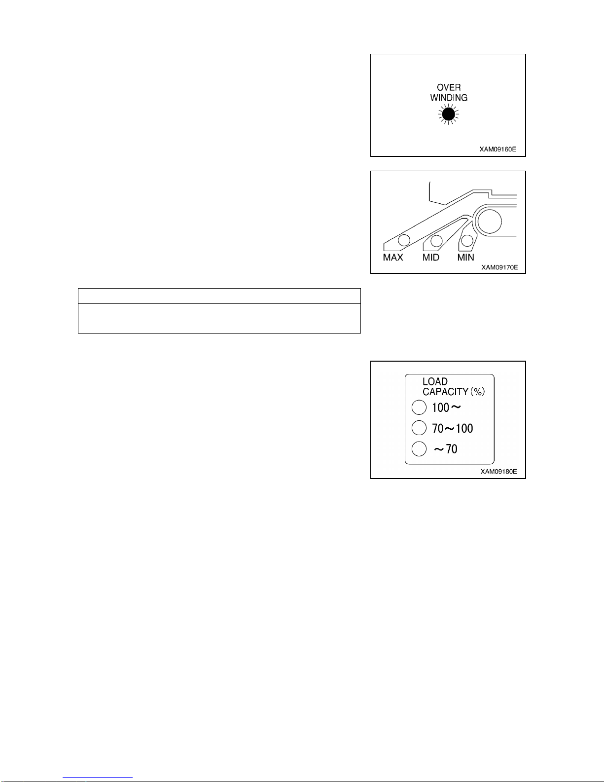
3-28
7. OVER WINDING LED (RED)
This LED flashes up when the hook is overwound, and issues
overwinding warning and causes an automatic stop.
This LED also flashes when the hook is stowed during the hook
stowing operation. This is normal.
8. OUTRIGGER EXTENSION LED (ORANGE)
The LED lights up to indicate the outrigger extension status.
• If any of the four outriggers has not properly reached the
maximum extension position, the “MIN” LED lights up.
• If all the four outriggers reach the maximum extension position,
the “MAX” LED lights up.
Even if you thought you had set the outriggers at the maximum
extension position, the “MIN” LED lights up if any of the outriggers
did not properly reach the maximum extension position.
NOTES
This machine is not capable of detecting the middle extension
position. Please be careful as "MID" LED does not light.
9. LOAD FACTOR DISPLAY (ORANGE)
This display indicates the status of the moment limiter load factor
by its illumination.
• Where the load factor is less than 70% of the rated total load, "70" LED lights up.
• Where the load factor is 70 to less than 100% of the “rated total
load, "70 - 100" LED lights up.
• Where the load factor is 100% or higher than the rated total load,
"100 -" LED lights up.
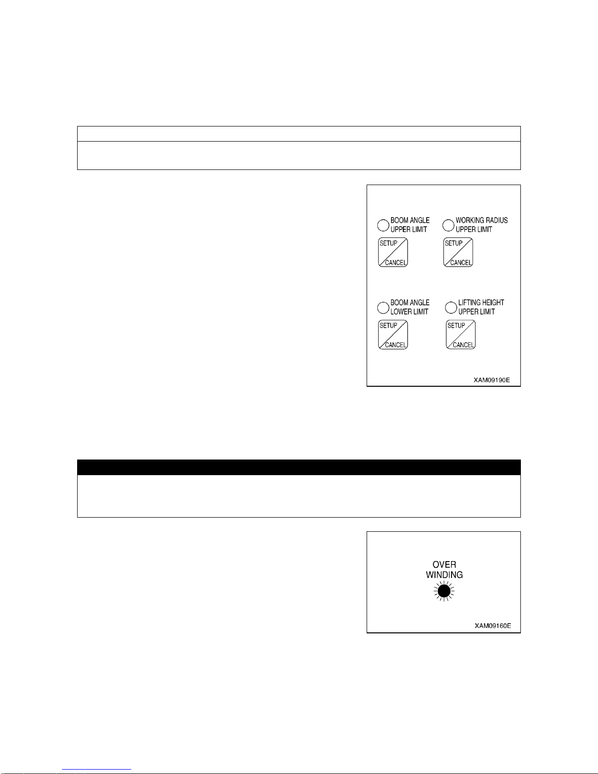
3-29
1.4.5 OTHER MOMENT LIMITER FUNCTIONS
[1] WORKING ENVELOPE RESTRICTION WARNING
When the working envelope gets close to the set restriction value, a warning is issued to notify the
operator and people around of the situation.
The last status of the set value for the working envelope restriction is memorized even if the starter switch
is turned to the OFF position.
NOTES
See “Operation 1.4.4 [1] Descriptions of Switches on Moment Limiter Display Unit” for how to set the
value for working envelope restriction.
When the working envelope has been set, the restriction will be as
follows.
1. SAFETY ZONE
• The appropriate working envelope restriction LED (red) lights
up.
• Green of the working status lamp lights up.
2. PRE-WARNING
• The appropriate working envelope restriction LED (red) lights
up.
• The alarm sounds intermittently.
• Yellow of the working status lamp lights up.
3. LIMIT WARNING
• The appropriate working envelope restriction LED (red) lights
up.
• Red of the working status lamp lights up.
• The alarm sounds continuously.
• The appropriate operation of the crane stops automatically.
[2] OVER HOIST DETECTOR
CAUTION
Pay attention to the distance between the hook and boom when raising the hook.
Extending the boom also raises the hook.
Always check the hook height when extending the boom.
When you overwind the hook when raising the hook or extending
the boom,
• The “Overwinding” LED (red) flashes.
• The alarm sounds continuously. (It stops sounding when the
operation lever is released.)
• The hook raising, boom extending and boom raising operation
stop automatically.
In case of auto stop, immediately perform the recovery operation.
Perform hook lowering and boom retracting operations as recovery
operations.

3-30
[3] BOOM UPPER LIMIT DETECTION
When the boom is raised and the boom angle reaches “about 77
degrees”, the boom raising operation stops automatically.
[4] BOOM LOWER LIMIT DETECTION
When the boom is lowered and the boom angle reaches “about 3
degrees”, the boom lowering operation stops automatically.
1.4.6 MOMENT LIMITER STARTING STATUS
CAUTION
• If the red of the working status lamp does not go off after completing the functional check of
the moment limiter, be sure to contact us or our sales service agency.
• If the travelling lever stand is set in the "Travel Position", the Moment Limter is not turned ON.
To turn it ON, don't forget to set the travelling lever stand in the "Crane Operation Position".
The moment limiter checks its function for 2 seconds when the starter switch is turned to the ON position.
Meanwhile,
• The red of the working status lamp lights up.
• All the LEDs light up.
Then, if the moment limiter and the sensors are normal upon the completion of the functional check of the
moment limiter, the red of the working status lamp goes off and green of the working status lamp lights up
indicating that the machine is ready for use.

3-31
1.4.7 MOMENT LIMITER ERROR CAUSES AND ACTIONS TO BE TAKEN
The moment limiter displays an error code at the “rated total load” display section on the display panel to
notify the error.
If an error code shown in the table below was displayed, contact us or our sales service agency.
Error Code
Error Details
Actions to Be Taken
E1L
The input to pressure sensor 1 is
lower than the specified value.
Check the installation of the pressure
sensor 1.
E1H
The input to pressure sensor 1 is
higher than the specified value.
E2L
The input to pressure sensor 2 is
lower than the specified value.
Check the installation of the pressure
sensor 2.
E2H
The input to pressure sensor 2 is
higher than the specified value.
E3L
The input to angle detector is lower
than the specified value.
Check the installation of the angle detector.
E3H
The input to angle detector is higher
than the specified value.
E4L
The input to length detector is lower
than the specified value.
Check the installation of the length
detector.
E4H
The input to length detector is higher
than the specified value.
EAD
The AD converter at the converter
section is not functioning properly.
Turn the starter switch to the OFF position
and then to the ON position again. If an
error is displayed again, change the
converter.
ERS
The communication between the
converter section and the display
unit is not carried out properly.
• Check the cable between the display unit
and the converter. If the cable is normal,
change the converter.
• Check the fuse built-in the converter.
E-E
Error with calibration memory.
This error is also issued when
calibration has not been done yet.
Turn the starter switch to the OFF position
and then to the ON position again. If an
error is displayed again, change the display
unit.
No displayed
---
Check the fuse built-in the display unit.
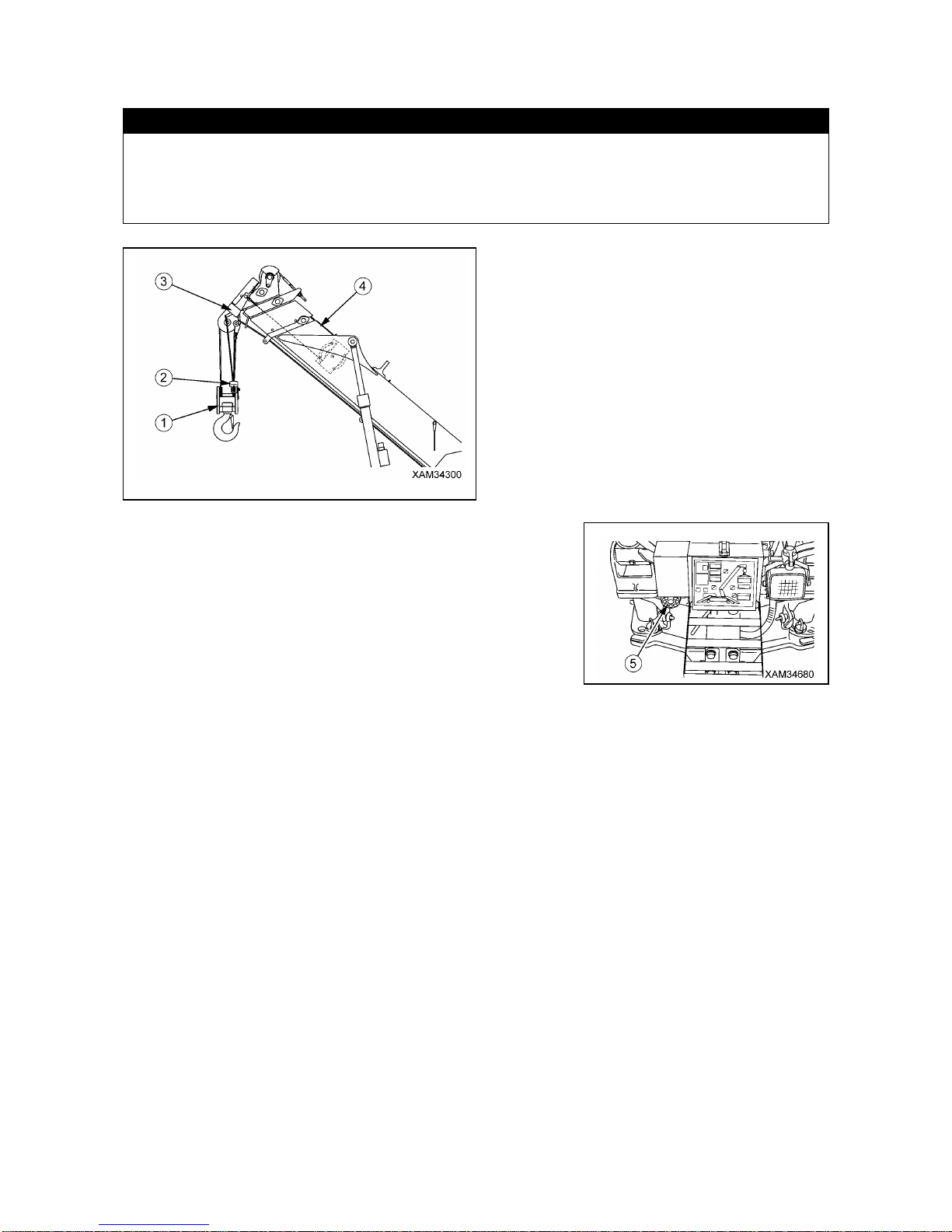
3-32
1.5 OVER HOIST DETECTOR
CAUTION
Pay attention to the distance between the hook block and the boom when raising the hook
block.
The hook block also raises when the boom is extended.
Always check the height of the hook block when performing the boom extending operation.
(1) Hook block
(2) Over hoist detector weight
(3) Over hoist detector
(4) Boom
The over hoist detector is a device which automatically stops
operation as listed below, it also sounds the Over hoist and
moment limiter alarm buzzer (5) to warn of an over hoisting
condition, when the hook block (1) comes close to the Boom tip
and lifts the weight (2) up:
• Hook raising
• Boom telescoping
• Boom raising
When the Over hoist and moment limiter alarm buzzer (5) beeps,
return all of the Winch lever, Boom telescoping lever and Boom
derricking lever to the NEUTRAL position immediately, then push
the Winch lever forward (Down).
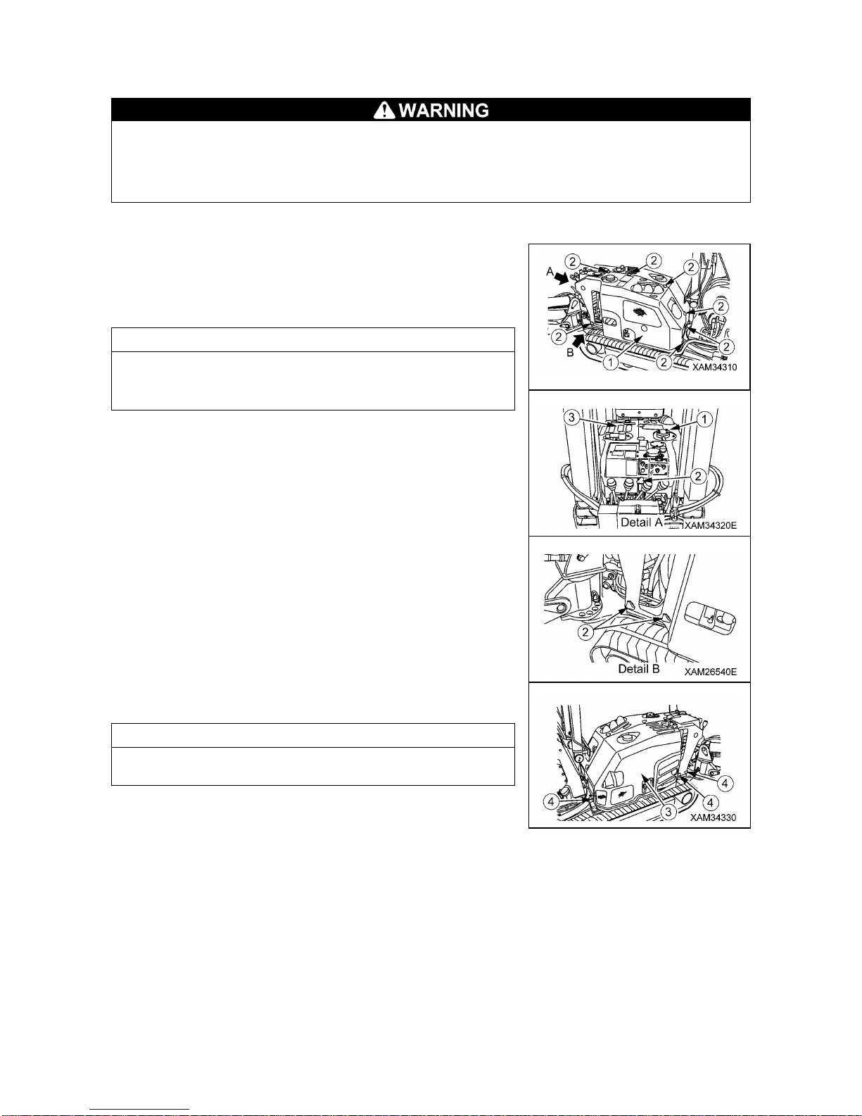
3-33
1.6 MACHINERY COVER
• Be sure to stop the engine and remove the starter switch key before removing the machinery
cover.
• Do not remove the machinery cover immediately after the operation while the engine is still
hot.
[1] REMOVING MACHINERY COVER
Remove the machinery cover with the following procedure when
performing inspection/maintenance inside the machinery cover.
1. Remove 9 mounting bolts (2) from the left side machinery cover
(1).
NOTES
The mounting bolts (2) are being used in quantity of 1 at the
crane operation unit, 3 at the top, 3 at the rear and 2 at the
forward left lower side.
2. Remove 3 mounting bolts (4) from the right side machinery
cover (3).
NOTES
The mounting bolts (4) are being used in quantity of 1 at the rear
lower side and 2 at the right lower side.
3. Remove the left side machinery cover (1).
4. Remove the right side machinery cover (3).
[2] INSTALLING MACHINE COVER
When you finished inspection/maintenance in the machinery cover, install the machinery cover using the
reverse procedure to that for removing it.
When you complete re-installation, always check each part for any interference condition.

3-34
2. OPERATIONS
2.1 CHECKS BEFORE OPERATION
2.1.1 CHECKS BEFORE STARTING THE ENGINE (VISIBLE CHECKS)
• This machine has a gasoline engine.
If it smells of fuel around the engine, the fuel may be leaking. Carefully check for cracks on the
fuel hose or fuel hose connections.
• Buildup of combustibles and oil leakage around the hot engine section such as engine and
muffler and around the battery can cause fire in the machine.
Carefully check around these areas. Should you find any abnormality, be sure to fix it or
contact us or our sales service agency.
Check the items shown in this section as routine surveillance before starting the first work of every day.

3-35
[1] CHECKING AROUND CRANE
• Look around and below the boom and post and look for any oil leak or similar. Be especially careful to
check the derricking cylinder and lower part of the winch motor near the post. If you find any abnormality,
repair.
• Check each part of the post for cracks, excessive deformation & contamination etc. In addition, check
bolts, nuts, pins and piping joints for any looseness, drop or damage etc. Be especially careful to check
for looseness of decelerator mounting bolt of the post, slewing ring or slewing device. If you find any
abnormality, repair.
• Check each part of the boom for cracks, excessive deformation, contamination etc. In addition, check
bolts, nuts, pins and piping joints for any looseness, drop & damage etc. Be especially careful to check
for excessive abrasion and damage of the boom support pin or derrick support pin. If you find any
abnormality, repair.
• Check for excessive damage and deformity of the over hoist weight wire rope of the overwinding alarm
device at the tip of the boom. If there is any abnormality, repair.
• Check for sagged electrical wire, loosened connection and trace of burns. If you find any abnormality,
repair.
[2] CHECKING WIRE ROPES
See "Inspection and Maintenance 8.6 [2] Replacement winch wire rope".
• Check the wire ropes for damage, deformation, wear, twists, kinks, corrosion, etc. If you find any
abnormality, replace.
• Check the bound condition of the wire rope ends. If you find any loosened wire rope end, replace.
• Check for irregular winding of the wire ropes (wind drum). If you find any irregular winding, rewind.
[3] CHECKING HOOK BLOCK
• Verify that the wire rope latch (1) of the hook block functions
normally. If there is any abnormality, repair.
• Rotate the hook and verify that the hook rotates smoothly and
that trunnion does not emit any abnormal sound.
If there is any abnormality, repair.
• Check the hook for any crack or excessive deformation.
If there is any abnormality, repair.
• If dimension a between the punch marks punched on the hook
became "105 mm or more" or the hook lower part dimension b
became "49.5 mm or less", replace the hook.
[4] CHECKING AROUND OUTRIGGERS
• Look below each of the outriggers and check for any oil leak etc. Be especially careful to check below the
outrigger cylinders. If you find any abnormality, repair.
• Check each of the rotaries, outriggers, holders and outrigger cylinders for cracks, excessive deformation
& contamination etc. In addition, check bolts, nuts, pins and piping joints for any looseness, drop or
damage etc. If you find any abnormality, repair.
• Pull out the position pin of each of the outriggers, rotate the relevant outrigger rotary and verify that the
operation is smooth. If you find any abnormality, repair.

3-36
[5] CHECKING UNDERCARRIAGE PARTS
Check each of the frames, rubber tracks, rollers, idlers and sprockets for cracks, excessive deformation &
contamination etc. In addition, check bolts, nuts and pins for any looseness, drop or damage etc. If you
find any abnormality, repair.
[6] CHECKING AROUND TRAVELLING DOLLY
• Look around and below the machine and check bolts, nuts, pins and piping joints for any looseness, drop
or damage etc. If you find any abnormality, repair.
• Look around and below the machine and look for any oil leak or similar. Be especially careful to check
below the hydraulic oil tank, travel/crane operation section and each travelling motor. If you find any
abnormality, repair.
• Look around and below the Machine and check for breakage, excessive deformation, contamination etc,
Also check lights such as the headlights and the working status lamp. If you find any abnormality, repair.
• Look around and below the machine and check for sagged electrical wire, loosened connection and
trace of burns. If you find any abnormality, repair.
• Check each of the frames, machinery covers and other parts for cracks, excessive deformation &
contamination etc. If you find any abnormality, repair.
[7] CHECKING AROUND ENGINE
• Check for fuel, oil or water leaking from the engine. If you find any abnormality, repair.
• Check the hot engine sections such as the engine muffler and around the battery for the buildup and
deposit of combustibles such as dead leaves, paper wastes, dust, oil, and grease. If there is any, remove
them.
• Check the starter, alternator, around battery and similar parts for sagged electrical cables, piping joints,
and the trace of burn. If you find any abnormality, repair.
[8] CHECKING AROUND TRAVEL OPERATION SECTION
• Verify that all of the travelling levers, acceleration lever, travelling lever stand lock lever and travelling
lever stand operate smoothly. If you find any abnormality, repair.
• Check the hour meter on the instrument panel for damages and dirtiness. If you find any abnormality,
repair. If dirty, clean.
• Verify that all of the switches on the instrument panel operate smoothly. If you find any abnormality,
repair.
• Check for sagging electrical wire, loosened connection and trace of burns. If you find any abnormality,
repair.
[9] CHECKING AROUND CRANE OPERATION SECTION
• Verify that all of the operation levers and acceleration lever operate smoothly. If you find any abnormality,
repair.
• Check the moment limiter display for damages and dirtiness. If you find any abnormality, repair. If dirty,
clean.
• Verify that all of the switches on the outrigger operation panel and the instrument panel operate smoothly.
If you find any abnormality, repair.
• Check for sagging electrical wire, loosened connection and trace of burns. If you find any abnormality,
repair.

3-37
2.1.2 CHECKS BEFORE STARTING THE ENGINE
Check the following in this section without starting the engine and before starting work every day.
[1] CHECKING/REFILLING OIL LEVEL IN ENGINE OIL PAN
Securely install the oil level gauge (filler cap) after checking the oil level and refilling with the oil.
If the oil level gauge falls during the operation, the hot oil spouts out of the pan, causing burns.
CAUTION
• See “Maintenance 5.1 Use of Lubricating Oil According to Temperature” for which oil to be
used. Using other oil than those specified may shorten the life of the engine. Be sure to refill
with the specified oil.
• Keep the engine oil at the appropriate level.
The oil level being too high will result in too much oil consumption and this tends to increase
the oil temperature, deteriorating the oil faster. The oil level being too low may burn out the
engine.
• Be careful not to let any foreign substance go into the filler opening when refilling with the oil.
1. Stop the machine on a level surface.
2. Pull the oil level gauge (G) out and wipe the oil with a disposable
cloth.
3. Insert the oil level gauge (G) into the oil filler and pull it out.
NOTES
Don't screw in the oil level gauge (G).
That causes oil to be filled higher than correct level.
4. If the oil level is between the “H” mark and “L” mark on the oil
level gauge (G), the oil level is normal.
5. If the oil level is lower than the “L” mark, refill with the engine oil
from the filler opening.
NOTES
Refill the engine oil until it almost reaches the oil filler port.
6. After refilling with the oil, securely install the oil level gauge (G).
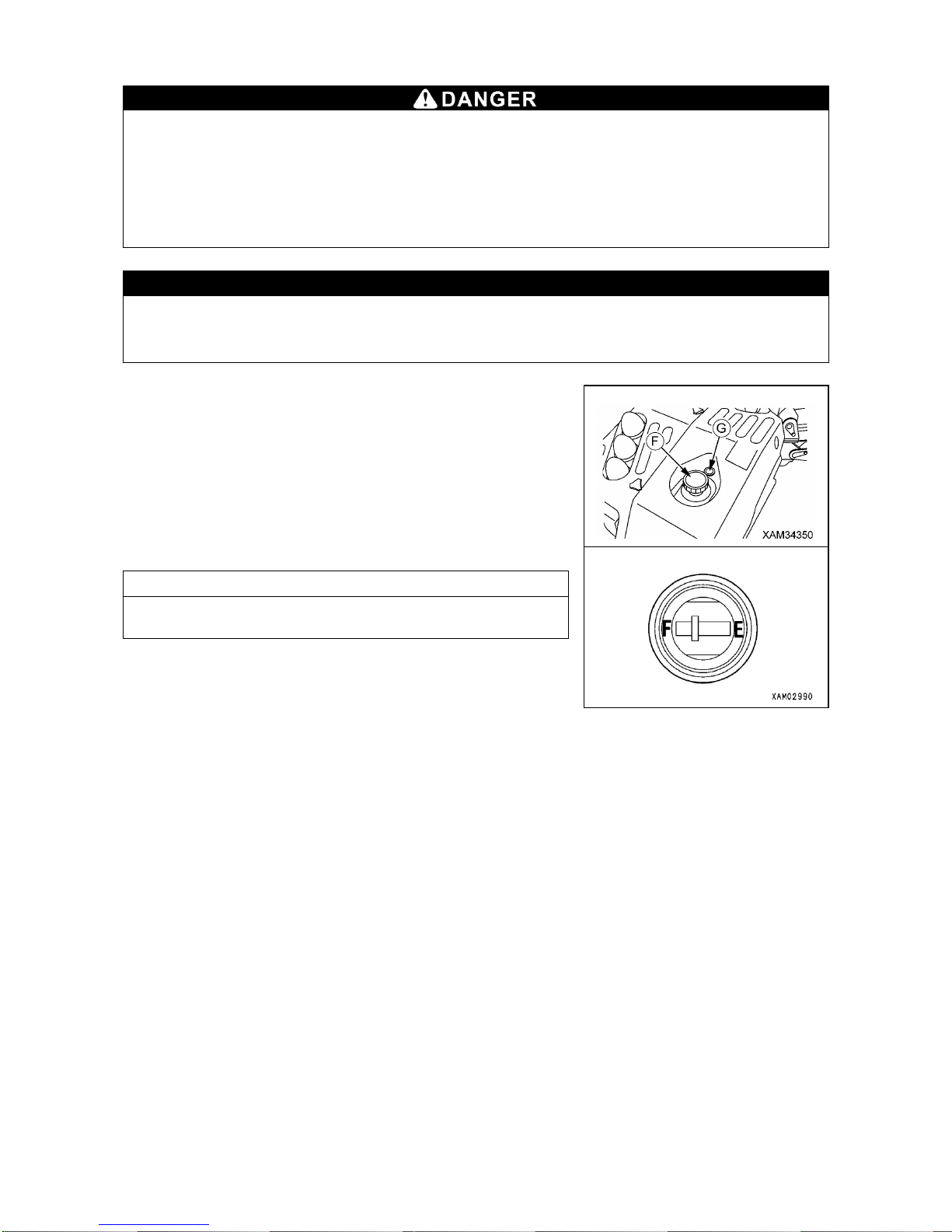
3-38
[2] CHECKING/REFUELING FUEL LEVEL IN FUEL TANK
• This machine uses gasoline (Octane number between 89 and 92). Be extremely careful with fire
such as cigarette.
• Be sure to stop the engine when refueling. If refueling was done with the engine in operation,
the fuel spilled on the section where it gets hot such as muffler can catch fire.
• Over-refilling may cause fuel spill. Refuel to the level slightly lower than the specified upper
limit level. If the fuel spills, be sure to thoroughly wipe it off.
• Be sure to close the tank cap after refuelling.
CAUTION
• See “Maintenance 5.1 Use of Lubricating Oil According to Temperature” for which fuel to be
used.
• Be careful not to let any foreign substance enter the filler opening when refueling.
1. Looking at the fuel gauge (G) on the top of the fuel tank, check if
the fuel is filled to almost full (around “F”).
2. If the fuel level is low, remove the tank cap (F) on the top of the
fuel tank and refuel from the filler opening while watching the fuel
gauge (G).
3. After refueling, turn the tank cap (F) to securely close it.
NOTES
Fill the fuel tank to full after finishing the work for the day.
 Loading...