

Page 1

350E-OM0912-03
OPERATION MANUAL
MINI-CRAWLER CRANE
Serial No. M01736 and up
Unsafe use of this machine may cause serious injury or death. Operators
must read this manual before operating this machine. This manual should
be kept near the machine for reference and periodically reviewed by all
personnel who will come into contact with it.
NOTICE
MAEDA has Operation & Maintenance Manuals written in some other
languages. If a foreign language manual is necessary, contact your local
distributor for availability.
Page 2

Page 3

0-1
CONTENTS
Item
Page
INTRODUCTION
1- 1
1. FOREWARD
1- 2
2. SAFETY INFORMATION
1- 3
3. OUTLINE OF THE MACHINE
1- 4
3.1 DESIGNATED TYPE OF WORK
1- 4
3.2 CONFIGURATION OF THE MACHINE
1- 4
3.3 FUNCTIONS THIS MACHINE IS PROVIDED WITH
1- 5
4. QUALIFICATION FOR OPERATING THE MACHINE
1- 5
4.1 QUALIFICATION REQUIRE FOR OPERATING CRANES
1- 5
5. GLOSSARY
1- 6
5.1 DEFINITIONS OF WORDS
1- 6
5.2 HOW TO READ WORKING RADIUS / LIFTING HEIGHT DIAGRAM
1- 7
5.3 HOW TO RATED TOTAL LOAD CHART
1- 8
5.4 HOW TO READ LOAD INDICATOR
1-12
SAFETY
2- 1
1. BASIC RULES
2- 2
2. RULES FOR OPERATION
2- 7
2.1 BEFORE STARTING UP ENGINE
2- 7
2.2 AFTER THE ENGINE HAS STARTED
2- 8
2.3 DURING CRANE OPERATION
2-12
3. RULES FOR TRANSPORTING A CRANE
2-18
4. RULES FOR HANDLING THE BATTERY
2-20
5. RULES TO OBSERVE IN CONNECTION WITH SERVICES
2-22
5.1 PRIOR TO CONDUCTING SERVICE
2-22
5.2 DURING SERVICE WORK
2-24
6. LOCATION FOR AFFIXING CAUTION PLATES
2-29
OPERATION
3- 1
1. NOMENCLATURE OF COMPONENTS
3- 2
1.1 NOMENCLATURE OF MACHINE COMPONENTS
3- 2
1.2 NOMENCLATURE OF TRAVEL CONTROL COMPONENTS
3- 3
1.2.1 CONTROL LEVERS
3- 4
1.2.2 SWITCHES
3- 6
1.2.3 METER, LAMP AND FUSES
3- 7
1.3 NOMENCLATURE OF CRANE CONTROL COMPONENTS
3- 8
1.3.1 CONTROL LEVERS
3- 9
1.3.2 SWITCHES
3-10
1.3.3 METERS AND LAMPS
3-11
1.4 OVER-HOIST PREVENTIVE DEVICE
3-12
1.5 EMO SWITCH (EMERGENCY STOP SWITCH)
3-13
1.6 OVER-LOWERING PREVENTION DEVICE
3-13
1.7 MACHINERY COVER
3-14
Page 4

0-2
Item
Page
2. OPERATION CONTROL
3-15
2.1 INSPECTION PRIOR TO STARTING UP THE ENGINE
3-15
2.1.1 VISUAL CHECK
3-15
2.1.2 INSPECTION BEFORE STARTING YOUR WORK
3-17
2.2 STARTING UP THE ENGINE
3-23
2.2.1 STARTING UP THE ENGINE WITH MAIN STARTER SWITCH
3-23
2.2.2 STARTING UP THE ENGINE WITH AUXILIARY STARTER SWITCH
3-24
3.2.3 STARTING UP THE ENGINE WITH RECOIL STARTER IN USE
3-25
2.3 OPERATION AND CHECKING AFTER ENGINE HAS STARTED
3-26
2.4 BREAK-IN OPERATION
3-28
2.5 TRAVEL POSITION OF THE MACHINE
3-28
2.6 STARTING THE MACHINE
3-29
2.7 CHANGING TRAVEL DIRECTION OF THE MACHINE
3-30
2.8 STOPPING AND PARKING THE MACHINE
3-31
2.9 STOPPING THE ENGINE
3-32
2.10 INSPECTION AND CHECK AFTER STOPPING THE ENGINE
3-32
2.11 RULES FOR TRAVELING
3-33
2.12 SETTING UP THE OUTRIGGER
3-34
2.13 MATTERS TO BE KNOWN BEFORE STARTING CRANE WORK
3-39
2.14 OPERATIONS PRIOR TO STARTING CRANE WORK
3-40
2.15 CRANE WORK POSITION
3-41
2.16 HOISTING AND LOWERING OPERATION
3-42
2.17 BOOM DERRICKING AND LOWERING OPERATION
3-42
2.18 BOOM TELESCOPING OPERATION
3-43
2.19 SWING OPERATION
3-44
2.20 ACCELERATOR LEVER OPERATION
3-44
2.21 HOW TO USE LOAD INDICATOR AND LOAD METER
3-45
2.22 STOWING THE CRANE
3-47
2.23 STOWING THE OUTRIGGER
3-48
2.24 MATTERS PROHIBITED IN CONNECTION WITH CRANE OPERATION
3-51
3. HANDLING OF RUBBER TRACK
3-53
3.1 SMART WAY OF USING IT
3-53
3.2 WARRANTY
3-53
3.3 PROHIBITED TYPES OF WORK
3-54
3.4 RULE FOR USING IT
3-55
4. HANDLING OF WIRE ROPE
3-57
4.1 STANDARD FOR WIRE ROPE REPLACEMENT
3-57
4.2 MEASURES TO TAKE WHEN WINCH WIRE ROPE IS TWISTED
3-58
5. TRANSPORT
3-59
5.1 LOADING AND UNLOADING
3-59
5.2 HOW TO LIFT THE MACHINE
3-60
5.3 RULES FOR LOADING
3-61
5.4 RULE FOR TRANSPORT
3-61
Page 5

0-3
Item
Page
6. HANDLINE IN COLD CLIMATE
3-62
6.1 PREPARATION FOR LOW AMBIENT TEMPERATURE
3-62
7. LONG TERM STARAGE
3-63
7.1 TREATMENT PRIOR TO STORAGE
3-63
7.2 DURING STORAGE
3-63
7.3 AFTER STORAGE
3-63
8. HANDLING OF BATTERY
3-64
8.1 RULES FOR HANDLING THE BATTERY
3-64
8.2 DE-MOUNTING AND MOUNTING THE BATTERY
3-65
8.3 RULES FOR CHARGING THE BATTERY
3-65
8.4 STARTING WITH BOOSTER CABLE IN USE
3-66
9. MEASURES TO BE TAKEN IN CASE OF ABNORMALITY
3-68
9.1 IN CONNECTION WITH ELECTRICAL COMPONENTS
3-68
9.2 IN CONNECTION WITH THE MACHINE
3-68
9.3 IN CONNECTION WITH ENGINE
3-69
INSPECTION AND MAINTENANCE
4- 1
1. RULES FOR CONDUCTING SERVICE
4- 2
2. BASICS OF SERVICE
4- 4
3. LEGALLY REQUIRED INSPECTION
4- 6
3.1 SAFETY REGULATION ON CRANE
4- 6
4. CONSUMABLE PARTS
4- 6
5. LUBRICATION OIL AND GREASE
4- 7
5.1 APPLICABLE LUBRICANTS BY AMBIENT TEMPERATURE
4- 7
6. STANDARD TOOLS AND STANDARD TIGHTENING TORQUE
4- 8
6.1 INQUIRY ON STANDARD TOOLS
4- 8
6.2 LIST OF STANDARD TIGHTENING TORQUE
4- 8
7. LIST OF INSPECTION AND SERVICE
4-11
8. WORKING PROCEDURE
4-13
8.1 FIRST 10 HOUR SERVICE
4-13
8.2 FIRST 20 HOUR SERVICE
4-13
8.3 FIRST 200 HOUR SERVICE
4-13
8.4 INSPECTION BEFORE STARTING YOUR WORK
4-13
8.5 IRREGULAR SERVICE
4-14
8.6 SERVICE IN EVERY 50 HOURS
4-29
8.7 SERVICE IN EVERY 100 HOURS
4-31
8.8 SERVICE IN EVERY 200 HOURS
4-32
8.9 SERVICE IN EVERY 500 HOURS
4-35
8.10 SERVICE IN EVERY 1000 HOURS
4-38
SPECIFICATIONS
5- 1
1. SPECIFICATIONS
5- 2
2. OVERALL DIMENSIONS
5- 3
3. TOTAL RATED LOAD CHART
5- 4
4. WORKING RANGE
5- 4
Page 6

0-4
Page 7

1-1
INTRODUCTION
1. FOREWORD
1-2
2. SAFETY INFORMATION
1-3
3. OUTLINE OF THE MACHINE
1-4
4. QUALIFICATION FOR OPERATING THE MACHINE
1-5
5. GLOSSARY
1-6
Page 8

1-2
1. FOREWORD
We thank you for selecting Maeda Mini-Crawler Crane MC-104C .
This manual is the guide book for your safe and efficient use of this machine.
This manual describes procedures for operation and service of this machine as well as matters to be
strictly observed while performing them.
Most accidents are attributable to operation, inspection or service where basic safety rules are
neglected.
Before operating this machine, please read this manual to fully understand the method of operation,
inspection and service.
Unless the content of this manual are observed, a serious accident could occur.
k WARNING
Careless use of this machine may result in serious injury or death.
Operator and service personnel should read this manual carefully before starting
operation or service of this machine.
This manual should be kept in a designated location as a guide, and should be referred to
periodically by all the personnel involved.
・Do not use this machine unless and until the description in this manual is totally
understood.
・Always keep this manual ready and convenient for repeated reference.
・In case of loss or damage, replace it immediately by ordering from your dealer.
・Before transferring this machine, be sure to give this manual to the new owner.
・Any descriptions, value or illustrations, are based on the information at the time of
publication.
Due to continued improvement on this machine, the service standards, tightening
torque, pressure, measuring method, adjust value or illustration are subject to change.
Such change may effect the maintenance service work. Before starting your work,
contact the supplier to obtain the latest information.
・ The description of safety is given in SAFETY INFORMATION on page 1-3 and in SAFETY
from page 2-1.
Page 9

1-3
2. SAFETY INFORMATION
For better understanding of this manual and caution plates on the machine, safety related messages are classified
as follows:
Indicates a pressing danger that may result in death or serious injury. Also indicated
is the method to avoid such risk.
Indicates a type of danger which is highly probable to result in death or serious injury.
Also indicated is the method to avoid such risk.
Indicates any status where it may result in light to medium injury or serious damage
to the machine. Also indicated is the method to avoid such risk.
Further, we have shown with following captions what is to be observed for the sake of the machine and what is
convenient to know.
Indicates the case where improper handling may cause damage to or shorten the useful
life of the machine.
Information which is convenient to know.
Rules described in this manual in connection with procedures and safety for operation and service, are applicable
only to those cases where this machine is used for designated work.
The manufacturer is not in a position to be able to presume all the cases to which this machine may be exposed by
users.
Accordingly, any rules shown in this manual or on the caution plates affixed to your machine does not cover every
situation relevant to safety.
For carrying out any operation or maintenance service not described in this manual, it should be understood that
necessary measures for safety are solely for the responsibility of the users.
Even for the responsibility of users, any work or operation expressly prohibited in this manual should never be
performed.
k DANGER
k WARNING
k CAUTION
CAUTION
NOTES
Page 10
1-4
3. OUTLINE OF THE MACHINE
3.1 DESIGNATED TYPE OF WORK
This machine should be used mainly for the following work:
・Crane work
This machine is a mobile crane with a boom type crane mounted on rubber tracked undercarriage. It is capable of
self propelled movement on job sites and crane work within total rated load.
In addition. The cable type remote controller is provided to allow remote control of the crane.
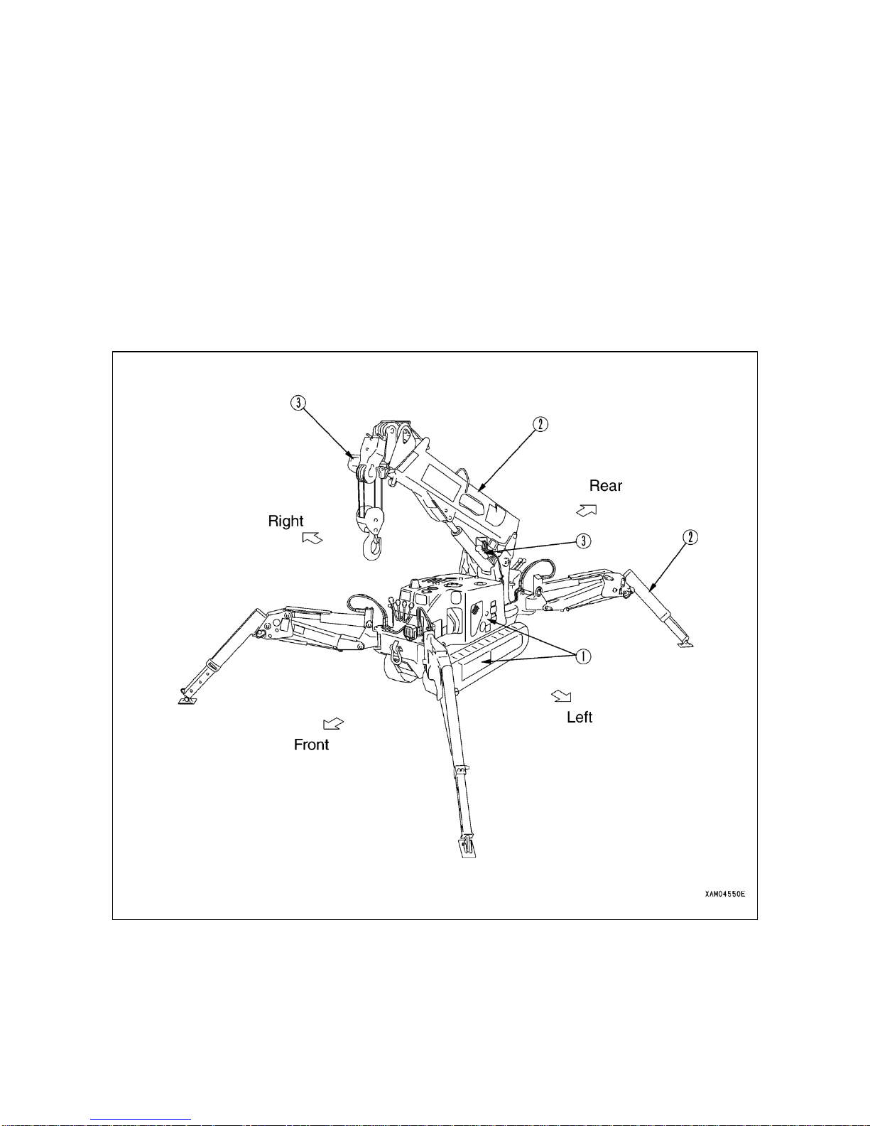
3.2 CONFIGURATION OF THE MACHINE
① Undercarriage
② Crane
③ Safety systems
In this manual, front, rear, right and left are in principle identified respectively
while viewing forward from the operator seat. Above sketch shows the crane
in working position.
OUTER DIMENSIONS DRAWING
Page 11

1-5
This machine consists of following major components:
[1] UNDERCARRIAGE
Consists of travel gear, engine, travel control and crane operation systems.
[2] CRANE
Consists of boom telescoping, boom derricking, swing and hook-block winches and outrigger systems.
[3] SAFETY SYSTEMS
Hook over-hoist warning system, hydraulic safety valve, Travel/Crane work selector system (which prevents crane
from functioning while traveling) and Outrigger/Crane work selector system (prevents outrigger actuation while
performing crane work) are provided.
3.3 FUNCTIONS THIS MACHINE IS PROVIDED WITH
[1] UNDERCARRIAGE
・This machine is designed to be more compact with the overall width for traveling reduced from that of our existing
models, enabling it to enter tighter spaces.
・Operation with two travel levers allows pivot turn and spin turn in addition to normal operation of forward, backward
travel or turning its travel direction.
[2] CRANE
・Equipped with auto-sliding type outrigger which allows the crane to work over uneven ground or in a tight space.
Outriggers can be extended in anyway to match terrain or conditions of a given job site.
・Boom telescoping, hoisting and swinging motions plus vertical move of hook block with winch operation, permits to
move suspended load to desired location within rated total weight and working radius.
・Remote control system allows remote control of the outrigger setting and any crane motion.
4. QUALIFICATION FOR OPERATING THE MACHINE
k WARNING
・Workmen's accidents in connection with cranes are occurring frequently. What we would like our
users
to recognize is the fact that even persons with rich experience are incurring accidents.
・For operation of this machine, be sure to observe safety rules shown in this manual.
4.1 QUALIFICATION REQUIRE FOR OPERATING CRANES
Qualification for operation of this type machine is provided in local laws and regulations. Check with the competent
authority or your Maeda dealer for detail.
Page 12
1-6
5. GLOSSARY
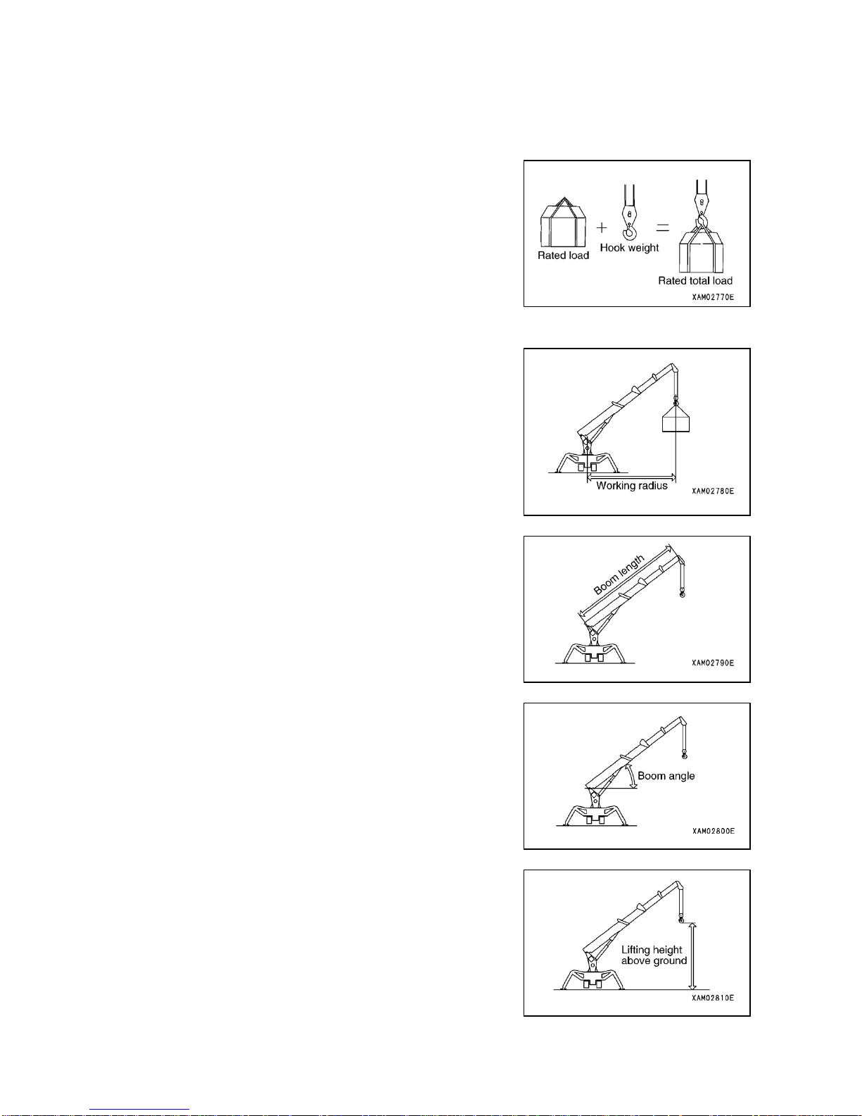
5.1 DEFINITIONS OF WORDS
[1] TOTAL RATED LOAD
Means the maximum load that can be lifted in accordance with length
and angle of the boom. Such load includes mass (weight) of hook and
rope.
[2] RATED LOAD
Means the load with the mass (weight) of hook and rope subtracted
from total rated load, which is the load that can be lifted.
[3] WORKING RADIUS
Means the horizontal distance from swing center to hook center.
[4] BOOM LENGTH
The distance from boom foot pin to sheave pin of top boom.
[5] BOOM ANGLE
The angle made between boom and horizontal ground line.
[6] LIFTING HEIGHT ABOVE GROUND
Vertical distance from hook bottom to ground with the hook lifted to the
maximum (upper limit).
Page 13
1-7
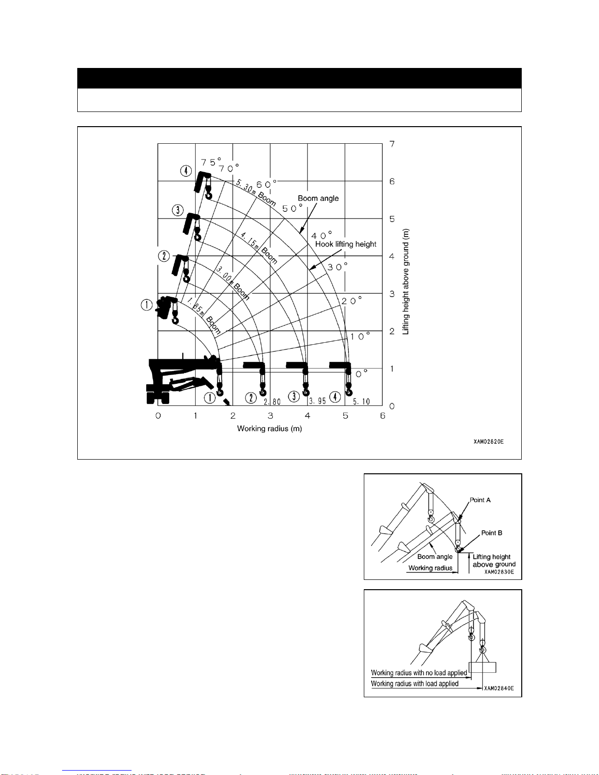
5.2 HOW TO READ WORKING RADIUS/LIFTING HEIGHT DIAGRAM
k WARNING
The working radius/lifting height diagram indicates the relation between the working radius, boom angle
and lifting height above ground of this machine, without any load suspended.
1. Point A in the sketch to the right represents boom angle while point B
represents the lifting height above ground. Working radius at points A
and B are the same.
2. “Working radius/Lifting height Diagram” is bases on “no-load” without
taking into consideration any bending of the boom.
In actuality, when load is lifted, the boom will bend causing the
working radius to slightly expand.
When working radius expands, the value of total rated load will be
reduced. It is important that you set your working plan with some
room added to the Diagram.
Page 14
1-8
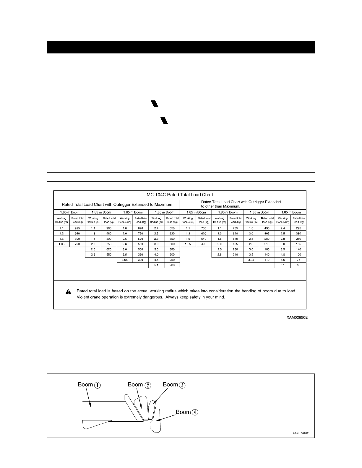
5.3 HOW TO READ TOTAL RATED LOAD CHART
k CAUTION
・Total rated load chart is based on level, hard ground. Depending on the outrigger setting or ground
conditions, machine may tip over.
・Total rated load chart is based on working radius with bending of boom and lifted load taken into
consideration.
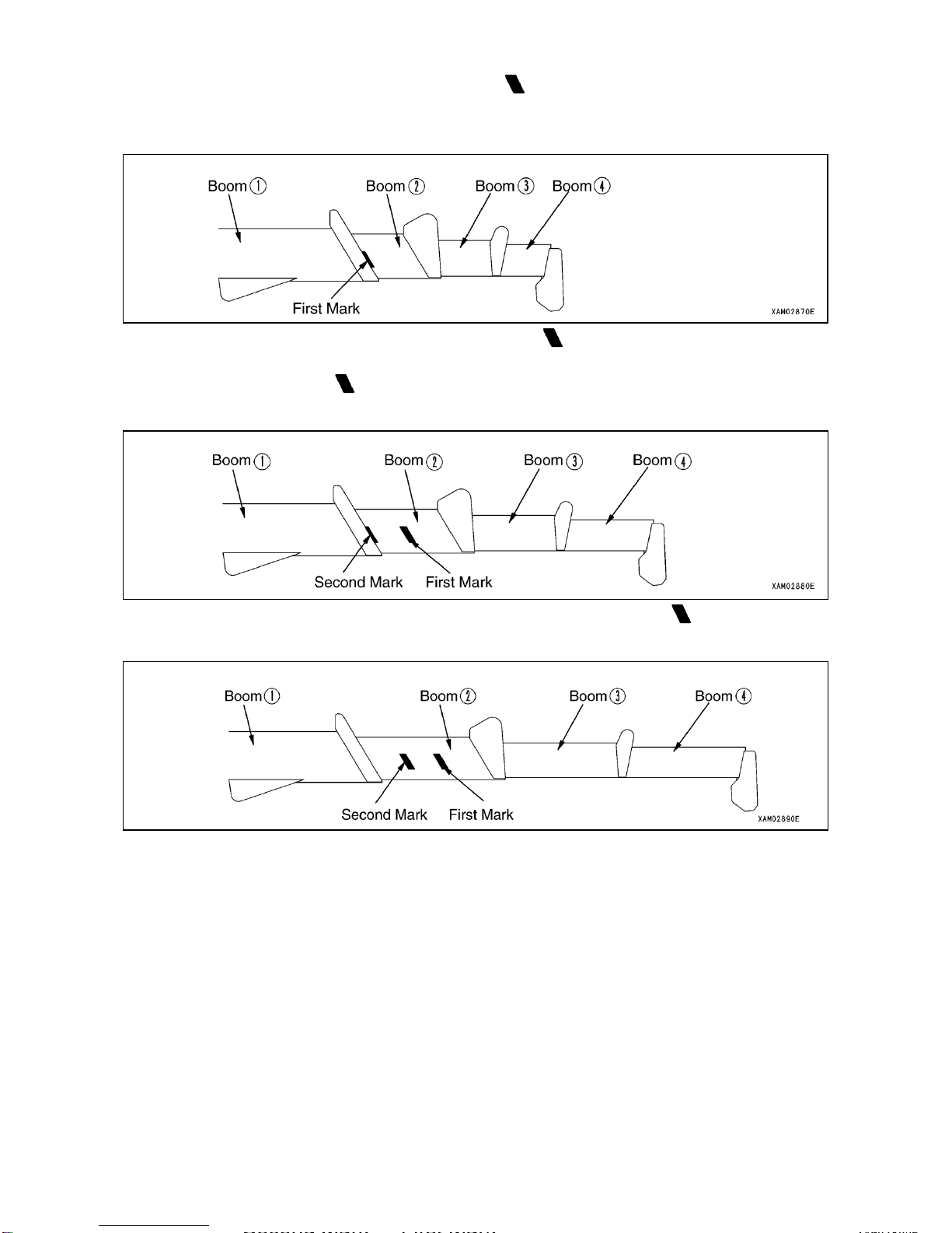
・If boom ② is extended to any extent, work should be performed within the capacity for the “3.00m
Boom”.
・When more than one half of the first mark is exposed from the boom ①, work should be carried
out within the performance for the "4.15m Boom".
・When more than one half or the second mark is exposed from boom ①, work should be carried
out within the performance for the "5.30m Boom".
・If working radius exceeds the value of Working Radius column in the chart by any extent, work should
be performed within the total rated load in the next column of Working Radius.
・Total rated load is shown with the mass of hook (15kg) included.
・Unless outrigger is extended to maximum, work should be performed in accordance with the “Total
rated load Chart without extending outrigger to maximum”.
Total rated load Chart shows the maximum load the crane is capable of lifting by the working radius, in accordance
with boom length and outrigger setting.
[1] BOOM LENGTH
"1.85m boom", "3.00m boom", "4.15m boom" or "5.30m boom" as appears in top space of Total rated load Chart
represents respective status as shown in sketches below:
1. "1.85m boom": All the booms retracted.
Page 15
1-9
2. "3.00m boom": Boom extended to such extent that the first mark of the boom (2) is exposed.
When the boom (2) is extended by any amount, however, work should be carried out according to the
performance shown in this column.
3. "4.15m boom": Boom extended to such extent that the second mark of the boom (2) is exposed. When
more than one-half of the first mark of the boom (2) is exposed, too, your work should be carried out in
accordance with the performance of this column.
4. "5.30m boom": All the booms extended fully. When more than one-half of the second mark of the boom (2)
is exposed as well, your work should be carried our in accordance with the performance of this column.
Page 16
1-10
[2] OUTRIGGERS EXTENDED TO THE MAXIMUM
k WARNING
・For crane work, be sure to extend all the outriggers. Never perform any crane work without setting up
outrigger. Machine may tip over causing serious injury otherwise.
・Outriggers should be extended while watching leveling instrument so that the machine is set
horizontally.
・For working without extending outrigger to maximum, see the values in "Total rated load Chart without
extending outrigger to maximum"
Working under improper value may cause the machine to tip over.
・If you have retracted any positioning pin of outrigger inner box or outrigger base by even one hole,
your work should be performed in accordance with the value of "Total rated load with Outrigger
Ex-tended to other than Maximum"
・Swinging 360 degrees with a load lifted may expose the machine to an unstable position. Reduce the
working radius and use sufficient care.
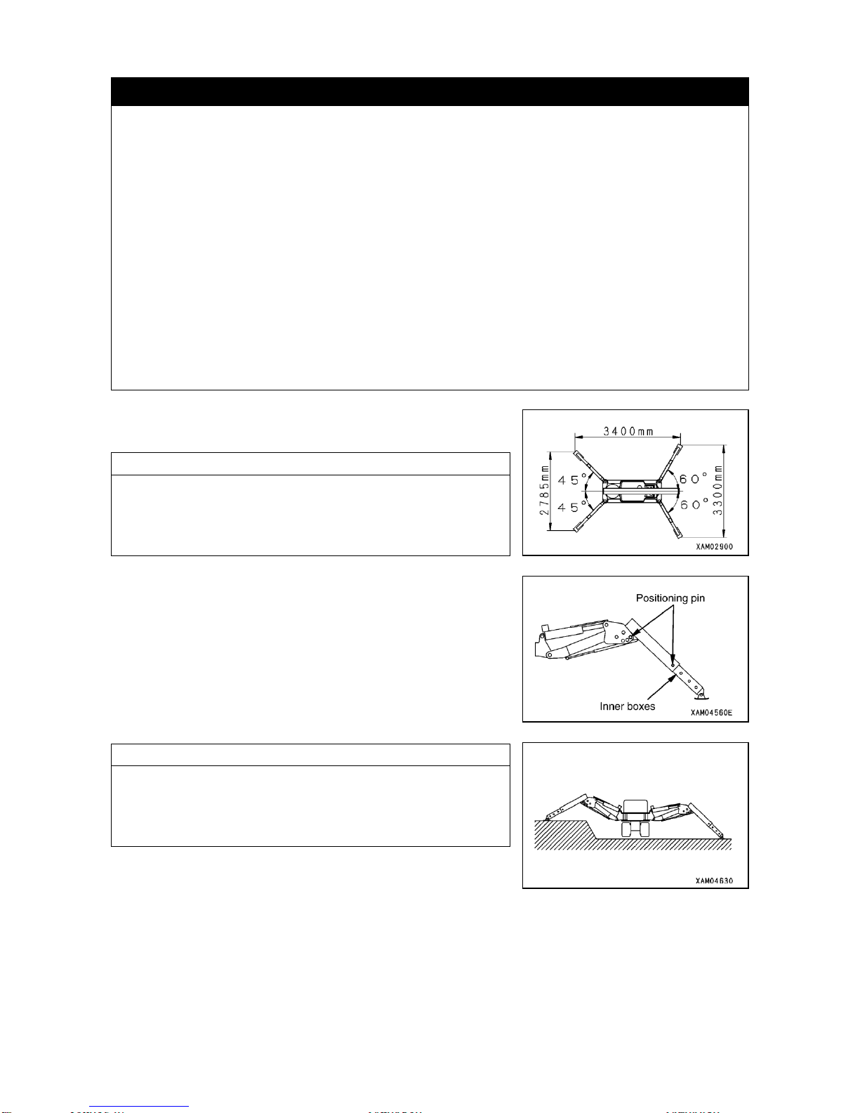
”Outriggers extended to the maximum” at the top of Total rated load
Chart indicates the status shown in the sketch to the right.
NOTES
"With the Outrigger extended to maximum" means that, with the
outriggers set to the standard extension (60 degrees front and 45
degrees rear), inner boxes of all the outriggers pulled out fully and
linkage bracket positioning pins set at the maximum position, the
outriggers are placed on level ground.
Any status other than that in the sketch to the right represents
"Outrigger Extended to other than Maximum". See “OPERATION, 2.12
HOW TO PLACE THE OUTRIGGERS" for proper placement.
NOTES
Even with all the outriggers extended to maximum, so long as the
grounding surface of any one of them is not flush with bottom surface
of track due to uneven terrain or the like, the status will have to be
defined as "Outriggers Extended to other than Maximum".
Page 17
1-11
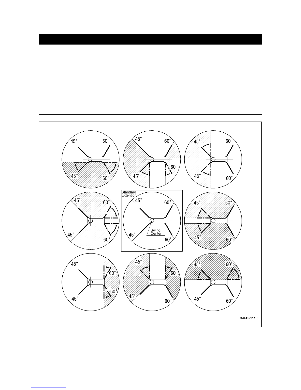
[3] ZONES WHERE CRANE WORK IS PROHIBITED ACCORDING TO THE PATTERN OF
OUTRIGGER PLACEMENT.
k WARNING
・Sketches below indicate the zones where crane work is prohibited according to the pattern of outrigger
placement (Shadowed area in the sketch). Within such zones, tipping-over of machine may take
place to result in serious personal accident. Never attempt to perform crane work in such zone.
・Of the 4 outriggers, the pair of either front and rear or right and left should always be set to the
standard placement (Front 60 degrees and rear 45 degrees). Even with the two outriggers set to
standard placement, the work should be performed in accordance with the value in Total rated load
Chart with Outriggers Extended to other than Maximum.
・Outrigger placement whereby work is allowed over entire circle, is only in accordance with "Standard
Extension" at the center in the sketch below.
Page 18
1-12
5.4 HOW TO READ LOAD INDICATOR
k WARNING
・For reading Total rated load with load indicator in use, be sure to observe following rules. Serious
accident including tipping over and damaging of the crane may be incurred otherwise:
1. Set up outrigger horizontally over hard ground.
2. Extend outrigger to the maximum.
・Before lifting a load, determine the boom length to be used (number of stages) and boom angle,
compare the total rated load at such position indicated by load indicator with the weight of the object
and make sure that the total load consisting of the weights of hook, object and rope never exceeds
the total rated load.
・When the outrigger is not extended to the maximum, any total rated load value indicated on load
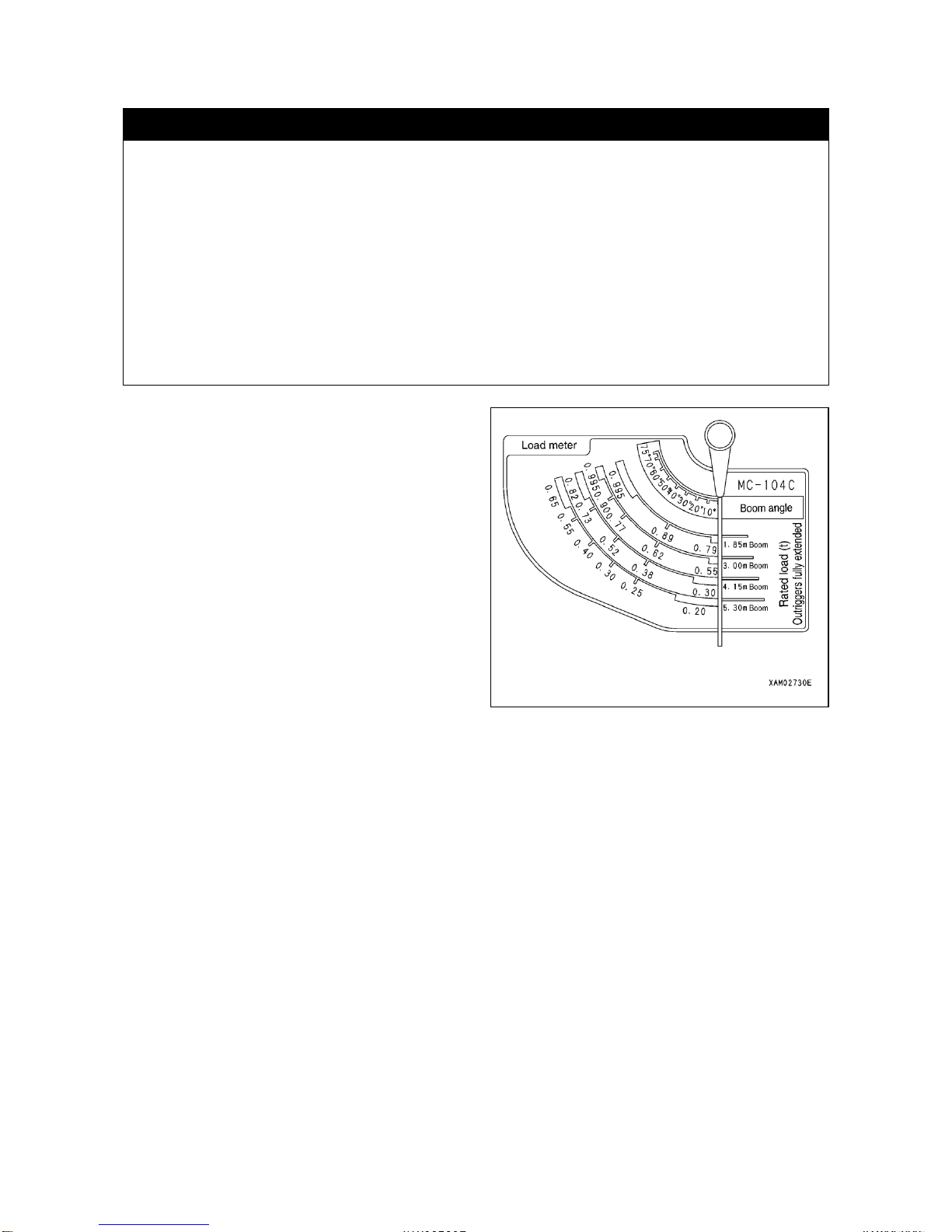
indicator is not useful. Read only the boom angle on the load indicator.Load indicator is affixed to
each side of No.1 boom and consists of pointer and scale board as shown in the sketch to the right.
Load indicator indicates the total rated load with outrigger
set on hard, level ground and extended to maximum (See
“INTRODUCTION, 5.3 [2] OUTRIGGER EXTENDED
TO MAXIMUM”), excluding bending of the boom. The
load indicator should be read to in the following manner:
・Read the value at the intersection of curve on scale for
the boom in use and pointer. It indicates the Total rated
load for the boom length in use at the time.
Page 19

2-1
SAFETY
1. BASIC RULES
2- 2
2. RULES FOR OPERATION
2- 7
3. RULES FOR TRANSPORTING A CRANE
2-18
4. RULES FOR HANDLING THE BATTERY
2-20
5. RULES TO OBSERVE IN CONNECTION WITH SERVICE
2-22
6. LOCATION FOR AFFIXING CAUTION PLATES
2-29
k WARNING
Read and observe these safety related rules thoroughly. Violating
this manual can result in an accident involving serious injury or
death.
Page 20
2-2
1. BASIC RULES
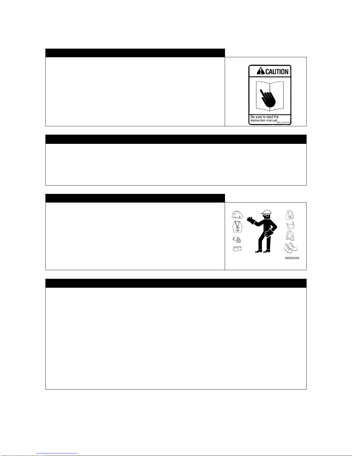
FOLLOW THE INSTRUCTION MANUAL AND CAUTION PLATES
• Read and understand this manual and caution plates affixed to the
machine. Operating the machine without fully understanding them may
lead to improper operation resulting in an accident involving personal injury
or damage to the machine.
• Understand proper method of using and servicing this machine to perform
operation safely.
• This manual and caution plates on the machine should always be kept
legible. When they become illegible, replace them quickly by obtaining
from your dealer.
QUALIFICATION TO OPERATE
• Official qualification may be required to operate this machine.
See “INTRODUCTION, 4. QUALIFICATION FOR OPERATION” in this manual for detail.
• Operation of this machine normally requires certain official qualifications for mobile crane or small sized mobile
crane as well as for performing slinging work. Check with your local authority for required qualifications
• Operator should receive sufficient training and acquire sufficient operating technique before starting to operate
the crane.
PROTECTIVE ITEMS AND CLOTHING
• Be sure to wear hard hat, safety shoes and safety belt.
• Select and wear protector suitable to particular work.
• Do not wear excessively large clothing or accessory which may be caught
by control lever or other projection, causing the machine to make
unintended movement.
RULES FOR SAFE OPERATION
• Follow instruction or signal of management and leader, to work with priority placed on safety.
• Work while observing the basics of crane work.
• Be sure to conduct prescribed inspection before starting operation and work.
• Do not work under weather conditions of gale, thunder or fog.
• Never operate the machine when you are tired, under the influence of alcohol or sleep inducing drugs.
• For performing operation, inspection or service, be sure to observe working rules, safety regulations and
operating procedures.
• Pay attention to surroundings and pedestrians when working. When a pedestrian carelessly approaches,
suspend your work and take measures to give warning.
• Always be alert while operating the machine against unexpected happenings and be ready to address them.
• Never operate the machine beyond its performance or application specified in this manual.
• Be sure to observe prescribed total rated load and working range.
• Never operate the machine looking aside, recklessly or forcibly.
• Pull out the key when leaving operation seat.
Page 21
2-3
BEFORE OPERATING A MACHINE THAT HAS BEEN LEASED TO OR DRIVEN BY OTHERS
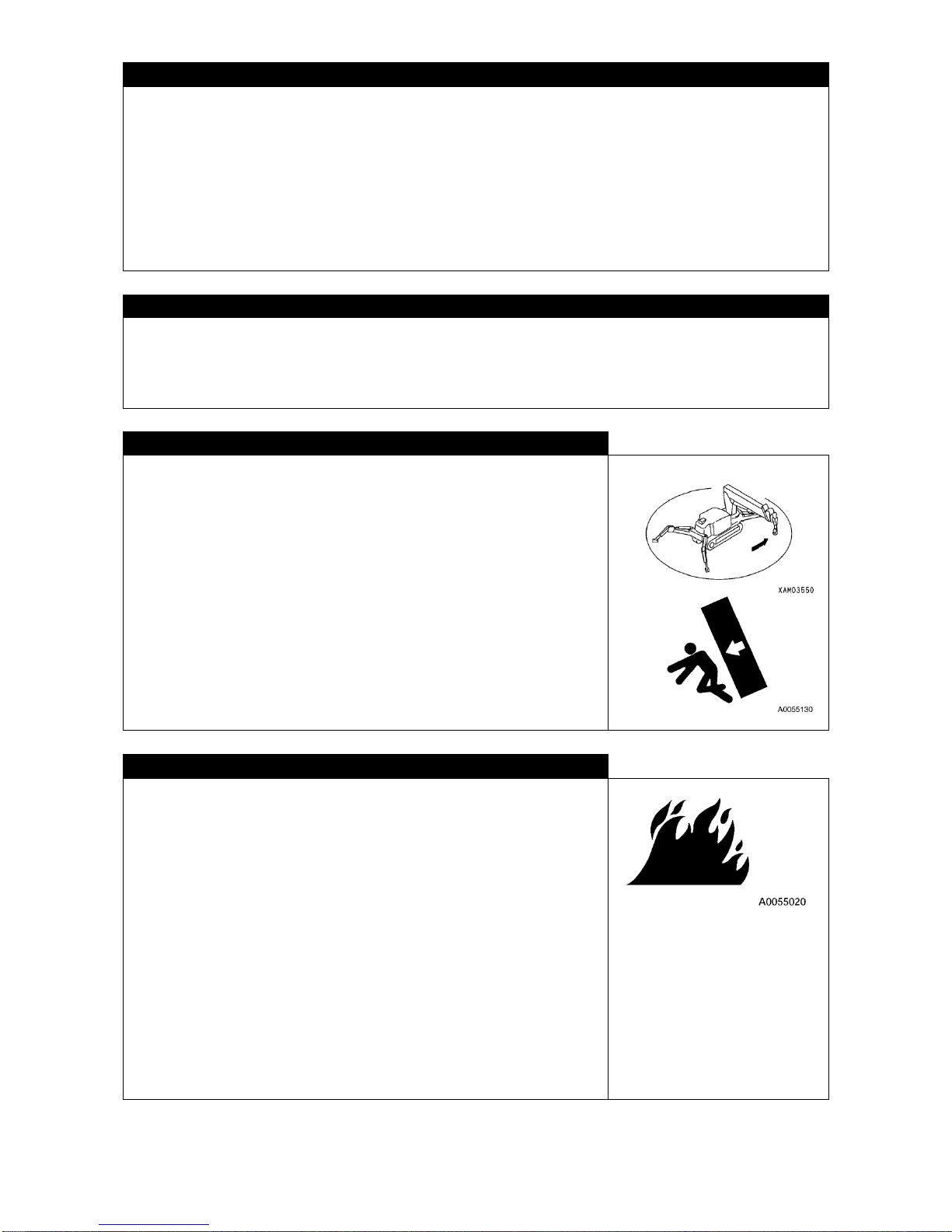
Before operating any machine which has been on rental or use by others, make sure of the following in writing.
Check the past services including voluntary periodical inspection, based on the inspection record as well:
1. Crane capacity
2. How the crane has been serviced
3. Habit or weakness of the particular crane
4. Miscellaneous matters to be watched in connection with operation.
(a) Function of brake and clutch
(b) Availability and function of flood light, rotational light, etc.
(c) Function of hook, winch, outriggers etc.
PROVISION FOR SAFETY PROTECTIONS
• Make sure that all the guards and covers are properly in place and if not, be sure to correct promptly.
• Use safety systems properly after fully understanding their usage.
• Never remove safety systems and always maintain them to function properly.
• Incorrect use of safety system may result in a serious accident.
• Do Not trust safety device too much to operate.
FOLLOW THE INSTRUCTION AND SIGNAL TO WORK.
• For crane work, designate a leader and signals beforehand to proceed with
the work in accordance therewith.
• Any work that is likely to create a blind spot should be carried out with
particular care by following the instruction and signal of the leader.
• For joint work with two or more cranes involved, “certain signals” should be
established and confirmed by everyone concerned.
• Crane work by nature contains the risk of causing workerユs arm or finger to
be caught between boom and undercarriage or clearance of moving parts
of boom derrick cylinder. Operator should make certain that there is no
person inside the working radius.
FOR PREVENTION OF TROUBLE
• Always conduct inspection and service carefully to prevent trouble from
developing.
• If any abnormality is felt with respect to your machine, suspend the work
immediately and report to a superintendent.
• With respect to the countermeasures to prevent consequential disaster,
have the sharing of duties established beforehand.
• When any fuel or hydraulic oil is leaking from the machine, do not operate it
but report to a superintendent and eliminate such leakage completely
before continuing the work.
This machine uses gasoline as its fuel. Pay particular attention to any fuel
leakage.
• Before leaving the machine, ground any lifted load, shutdown engine and
remove the engine key.
Page 22
2-4
TEMPORARY STORAGE OF TROUBLED MACHINE
For temporary storage of troubled machine waiting for service, let everyone on the job site know that the use of
machine is prohibited in the following manner.
・Post the prohibition conspicuously, with outline of trouble, personnel to contact and time limit for storage
indicated.
・For parking such machine, apply chocks to rubber track for prevention of rolling.
・Remove engine key before leaving the machine.
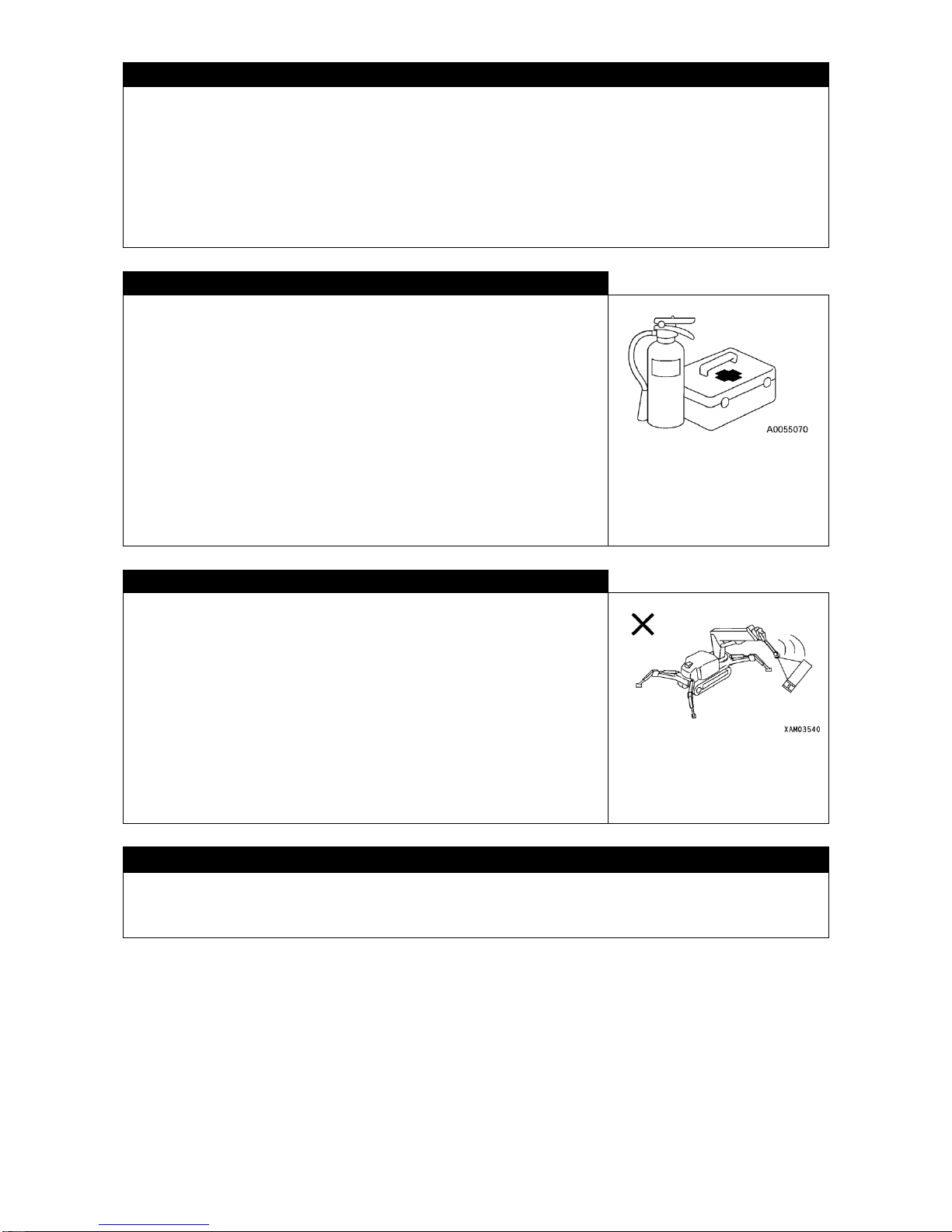
PROVISION OF FIRE EXTINGUISHER AND FIRST AID KIT
Be sure to observe following in preparation for unexpected injury or fire:
・Have fire extinguisher installed at designated location and its instruction
label read by everyone for ready use in emergency.
・Determine the location to keep first aid kit. It should be periodically checked
and replenished as required.
・Have measures against and procedures for injury or fire established
beforehand
・Have procedures for notifying an emergency contact (doctor, ambulance,
fire station) established and displayed conspicuously so anyone at the site
can act properly.
WORK REASONABLY AND CAREFULLY
・Abrupt lever operation and jerky machine operation should be avoided.
・When two or more cranes are closely positioned to work, operate them
carefully, paying attention to avoid tipping over due to contact. Place a
guide as necessary for prevention of such contact.
・When you notice any trouble or danger, discontinue the work immediately to
avoid the risk.
・Discontinue your work under bad weather (heavy rain, gale, thunder or
dense fog). Such judgment should be made in accordance with “Standard
for discontinuing work” as well as judgment of leader.
DO NOT MAKE MODIFICATION
Do not make any modification to your machine without our written consent. Any modification involves an issue of
safety and should be discussed with your Maeda dealer. We can not be responsible for any injury or other trouble
due to modification without our consent.
Page 23
2-5
SAFETY DURING REFUELING
・This machine operates using gasoline. Make sure to use fuel of proper
type. Wrong fuel will cause damage to engine.
・Be sure to shutdown engine for refueling. Refueling with engine running
may cause inflammation of spilled fuel at heated muffler.
・Over-refueling is dangerous with spilling. Try to refuel on the lower side of
specified level. If spilled, be sure to wipe it off completely.
・After refueling, be sure to close tank cap firmly.
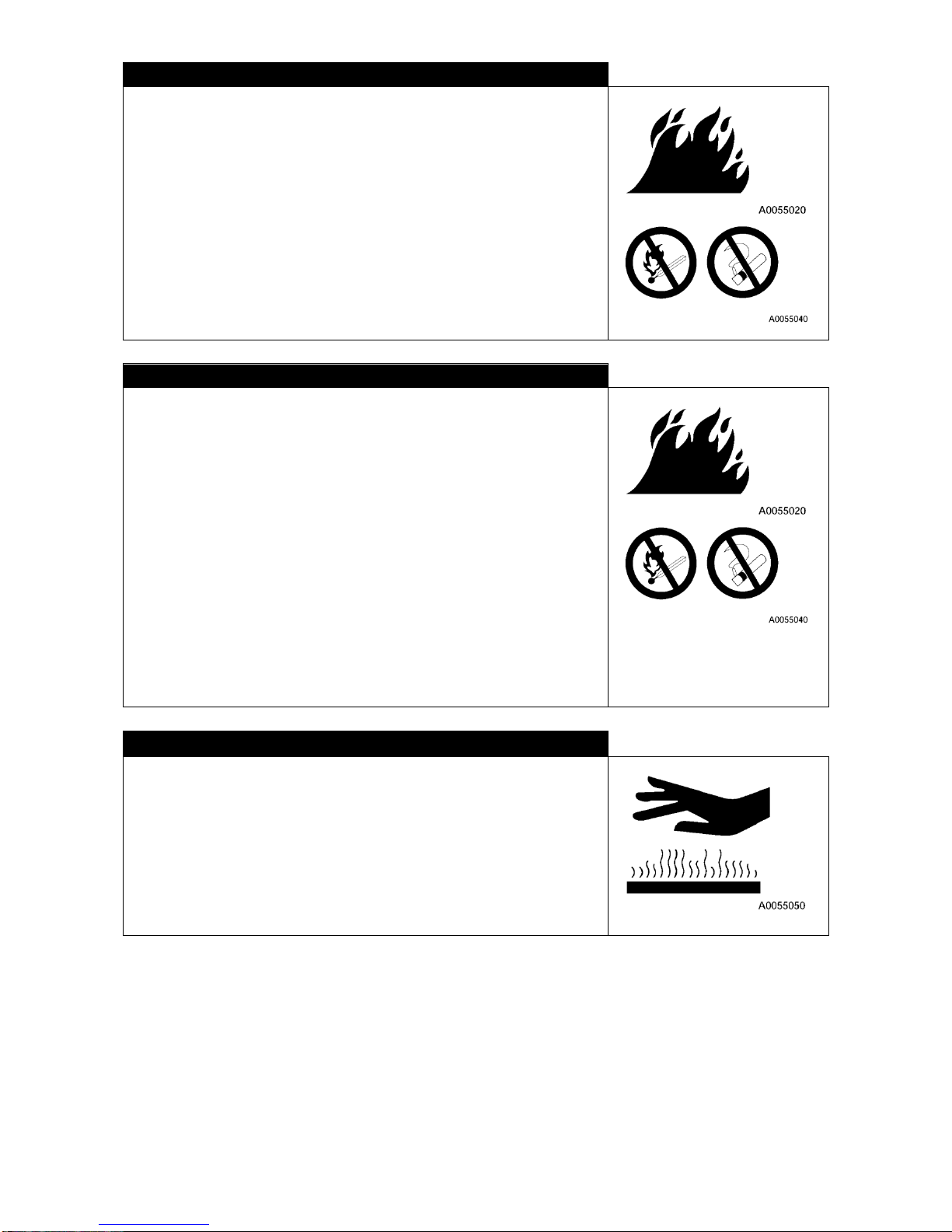
DO NOT ALLOW ANY FIRE TO APPROACH OIL
Inflammation may result if any fire should approach fuel, hydraulic oil or
engine oil. Observe following rules strictly:
・Do not allow lighted cigarette or match to approach any inflammable matter.
・Cap of fuel or oil can should be closed tightly.
・Fuel or oil should be stored in well ventilated area.
・Fuel or oil should be stored at a specified location and do not allow any
unauthorized person to approach.
・Do not leave the spot during replenishment.
During refueling in particular, be sure to observe rules provided in
preceding subparagraph “Safety during refueling”.
・Any fuel or oil spilled during replenishment should be wiped off
immediately.
HIGH TEMPERATURE
Immediately after operation, engine oil or hydraulic oil is hot and pressure has
been built up inside the hydraulic tank. Under such condition, you may incur
scalding by removing cap or replacing oil, coolant or filter. Wait for the
temperature to drop before proceeding with following procedure:
・To avoid blowing of hot oil, shutdown engine and wait for the temperature
to drop. Loosen cap slowly to release pressure before removing it.
(Feel the oil temperature by holding your hand close to the tank surface
but not by touching it directly.)
Page 24
2-6
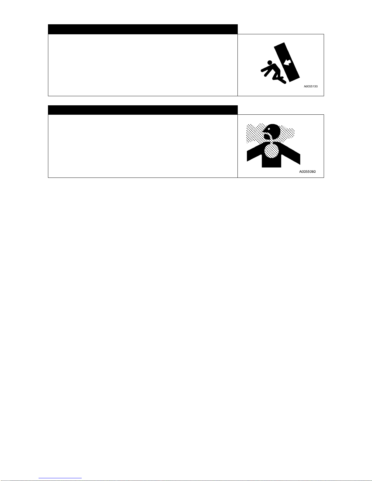
TO AVOID INJURY DUE TO CRANE
To avoid accident resulting in serious injury or death, do not place any part or
whole of your body in clearances such as follows:
・Between boom and undercarriage
・Between outrigger float and ground
・Between boom or post and hoist cylinder
・Between winch drum and wire rope
・Between sheave and wire rope
・Between track and ground
EXHAUST GAS
For starting up engine or handling fuel, cleansing oil or paint indoors or in
poorly ventilated area, be sure to open window or door for prevention of
poisoning by gas. If ventilation is still insufficient even with window or door
opened, install ventilation fan.
Page 25
2-7
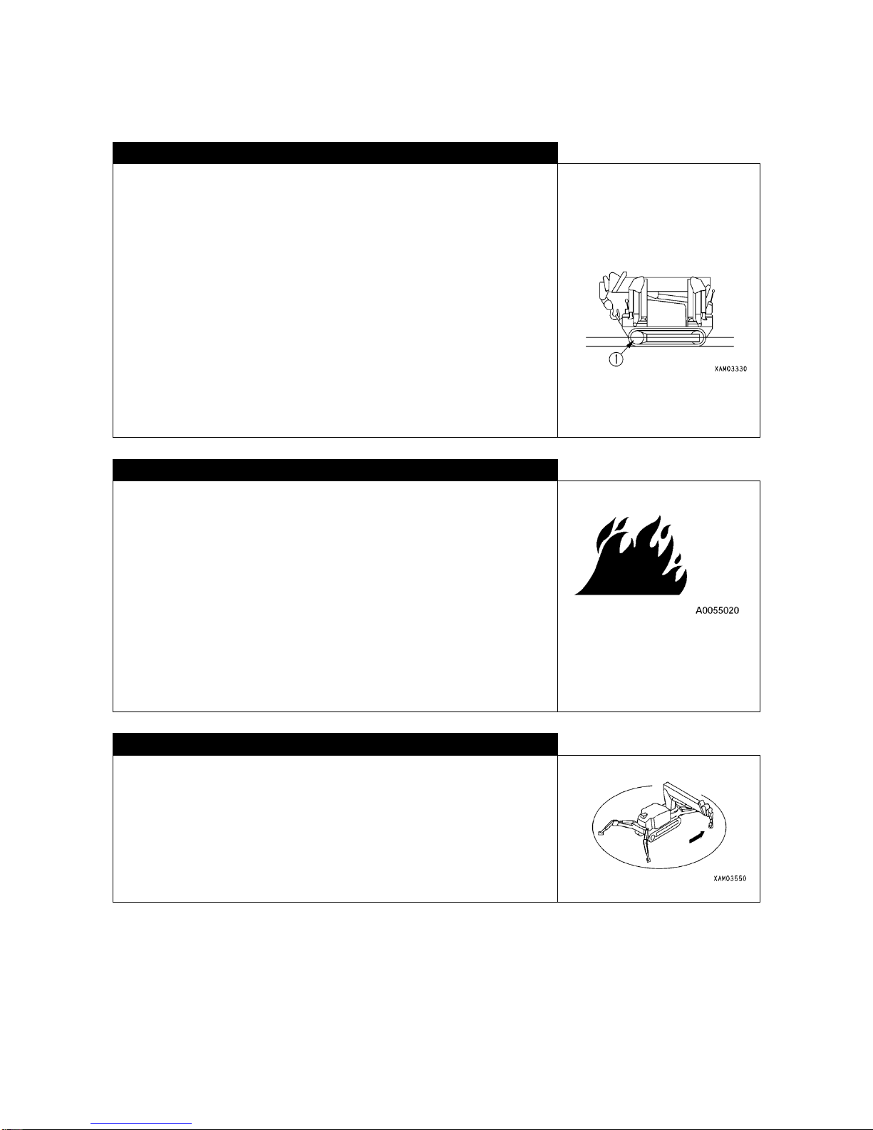
2. RULES FOR OPERATION
2.1 BEFORE STARTING UP ENGINE
SECURING SAFETY IN JOB SITE
・Make sure that there is no danger in job site before starting your work.
・Check ground and surface conditions of job site to select the most suitable
work method.
・Eliminate inclination in job site where possible, before proceeding with your
job. In case of heavy cloud of dust, water the job site.
・For work on road, place guide or fence to prohibit entry and secure safety
of pedestrian or machine.
・Take necessary measures to prohibit entry of unauthorized person to job
site.
Approaching moving machine may lead to serious accident of injury or
death by contacting or being caught.
・For traveling in water or crossing a ford, check the ground conditions, depth
and speed of flow first to make sure that it does not exceed the allowable
depth .
* See “OPERATION, 2.11 [2] ALLOWABLE DEPTH OF WATER”, for
detail.
CHECKING THE ENGINE BEFORE STARTING UP
Prior to the first start up of the day, conduct following inspection:
Its negligence may result in serious accident involving injury or death.
・Check for leakage of fuel or oil, deposit of inflammable matter around
engine or battery.
* See “OPERATION, 2.1.1 CHECKING AROUND THE MACHINE”, for
detail.
・Check fuel and hydraulic oil tanks for proper level, air cleaner for clogging,
wiring for any damage and function of safety systems and instrument.
* See “OPERATION, 2.1.2 INSPECTION BEFORE STARTING YOUR
WORK”, for detail.
・Make sure that control levers are in Neutral. Check that control linkages
function satisfactorily.
Based on the result of above checking, be sure to correct any abnormality.
RULES FOR STARTING UP THE ENGINE
・Before starting up the engine, make sure that there is no person or other
obstacle within the radius of boom swing.
・Be sure to sound horn for warning when starting up your engine.
・Do not use short circuiting of starter circuit to start the engine. It may cause
fire.
Page 26
2-8
2.2 AFTER THE ENGINE HAS STARTED
INSPECTION AFTER STARTING THE ENGINE
Negligence of inspection after starting engine will delay detection of trouble in machine resulting in personal injury
or damage of machine.
Inspection should be carried out in a wide area without obstacles. Do not allow anyone to approach the machine.
・Check actuation and travel of the machine, function of outrigger, and function of crane including winching and
hoisting, telescoping, and swinging of boom.
・Check for abnormal sound, vibration, heat or smell of the machine or leakage of air, oil or fuel. Pay particular
attention to the leakage of fuel.
・Any abnormality should be corrected whenever it is detected. Using the machine without correction may cause
unexpected personal injury or machine trouble.
RULES FOR STARTING THE MACHINE
In order to avoid serious injury or death, be sure to observe following rules
whenever you move the machine.
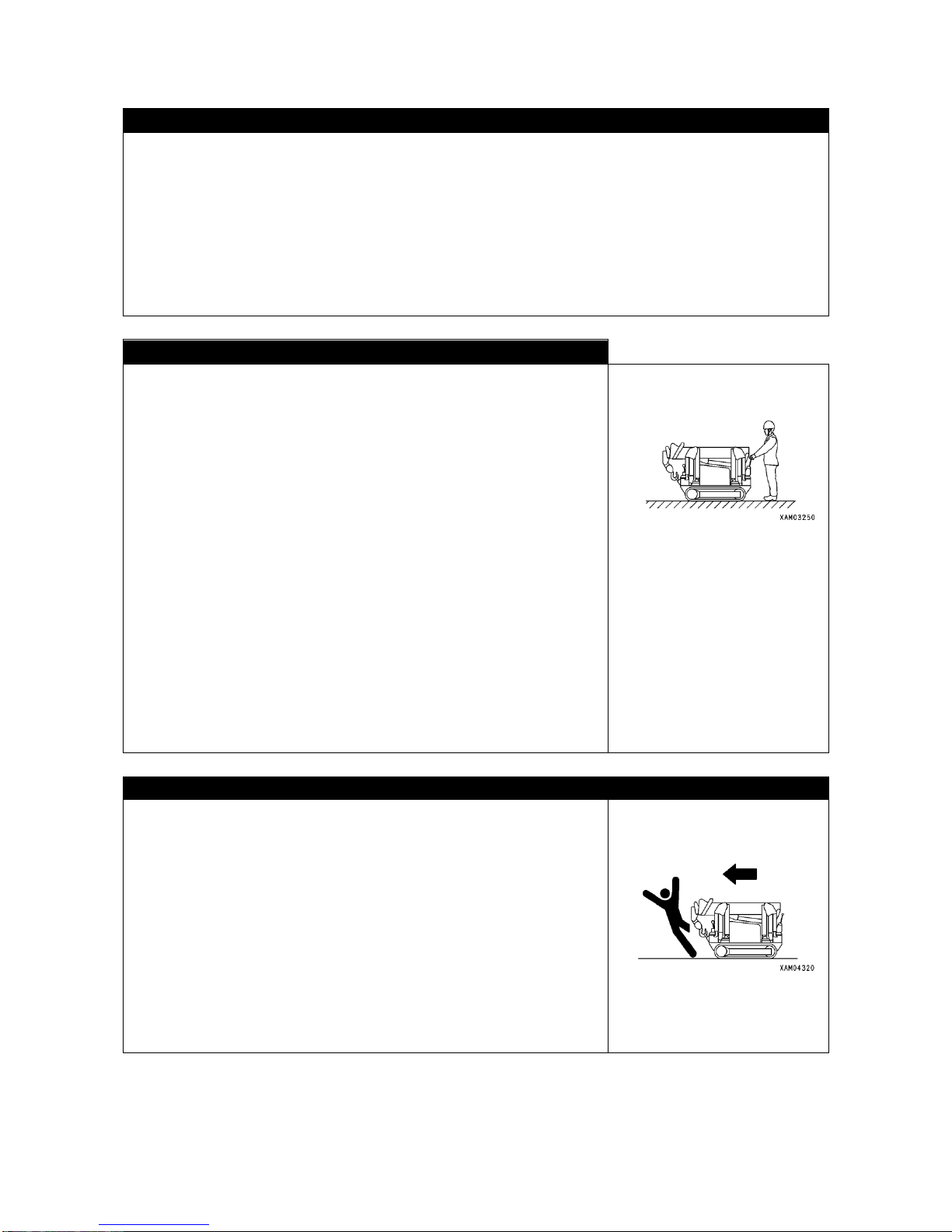
・Let the machine assume “Travel Position" as shown in sketch to the right:
Do not travel the machine without locking the hook block.
・Lower and retract the boom all the way.
・Engage the hook block to its hanger.
・Retract the outrigger.
* See “OPERATION, 2.5 TRAVEL POSITION OF THE MACHINE”, for
detail.
・Make sure again that there is no person or other obstacle around, before
starting to travel.
・When starting, sound the horn for warning.
・When traveling, be sure to stand in front of the travel lever located on the
travel control panel side. When the machine starts moving, walk and keep
your pace with the machine speed.
・This machine is not designed to carry any personnel or load on its carrier or
boom, when traveling.
• When traveling, stow hook and outrigger, and make sure the surrounding
safety.
• When stowing outriggers, insert each position pins completely to lock.
RULES FOR REVERSING TRAVEL OR CHANGING TRAVEL DIRECTION
In order to avoid serious injury or death, be sure to observe following rules
whenever you move the machine.
・Before switching from forward to reverse travel or vice versa, decrease
speed on the earlier side and bring the machine to a complete stop.
・For switching forward/reverse or changing direction, sound the horn to give
warning.
・Make sure that there is no person around the machine. Particularly,
because there is a blind spot in front of the machine, stop the machine as
necessary to make certain that there in no person in front or around the
machine.
・Use a guide wherever hazardous or view is poor.
・Do not allow any person to enter any area where you are traveling or
changing direction in.
Page 27
2-9
RULES FOR TRAVELING
In order to avoid serious injury or death, be sure to observe following rules
whenever you travel the machine.
・While traveling, pay attention.
・Avoid speeding and making jerky start or stop motions of sudden turns.
Avoid zigzag travel.
・When any abnormality is detected during operation such as abnormal
noise, vibration, smell, error in instrument or leak of fuel or oil, stop the
machine immediately at appropriate location to check for the cause.
・Avoid making sudden change of direction. It may cause the loss of
balance or damage the machine or nearby structure.
・For traveling over uneven ground, use low speed to avoid tipping over and
do not make jerky operation for changing direction. Try not to go over
obstacle where possible. If inevitable, use as low speed as possible.
Further, do not go over any obstacle which may cause the machine to
incline extremely (more than 10 degrees). While traveling, for prevention of
contacting with other machine or structure, keep a roomy distance from
them.
・For traveling in water or crossing a ford, check the ground conditions,
depth and velocity of flow, not to exceed the permissible depth.
See “OPERATION, 2.11 [2] PERMISSIBLE WATER DEPTH”, for detail.
・Before traveling over any bridge or other structure in privately owned land,
make sure that they withstand the weight of this machine. As for public
road, check with competent authority and follow its instruction.
• Do Not travel with load hoisted.
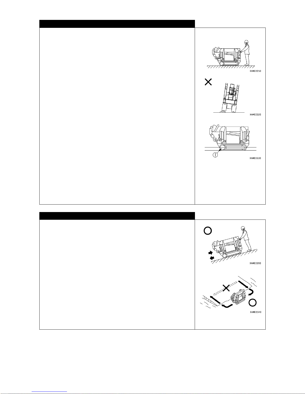
RULES FOR TRAVELING ON SLOPE
In order to avoid serious injury or death, be sure to observe following rules
whenever you travel on slope.
・When traveling on a slope, operator should always stand on upper side of
the machine.
・When traveling on slope, use care for tipping over or skidding sideways.
・Do not attempt to change travel direction on or to cross a slope. Go down to
flat area and detour for safety.
* See “OPERATION, 2.11 [3] RULES FOR TRAVELING UP- OR
DOWNHILL”, for detail.
・On grass, fallen leaves or wet steel plate, even with small inclination,
machine is more likely to skid sideways than imagined.
・Avoid to position your machine laterally to slope where possible and try to
slow down. When going downhill, travel slowly. Apply brake (travel lever
in Neutral position) as necessary.
Page 28
2-10
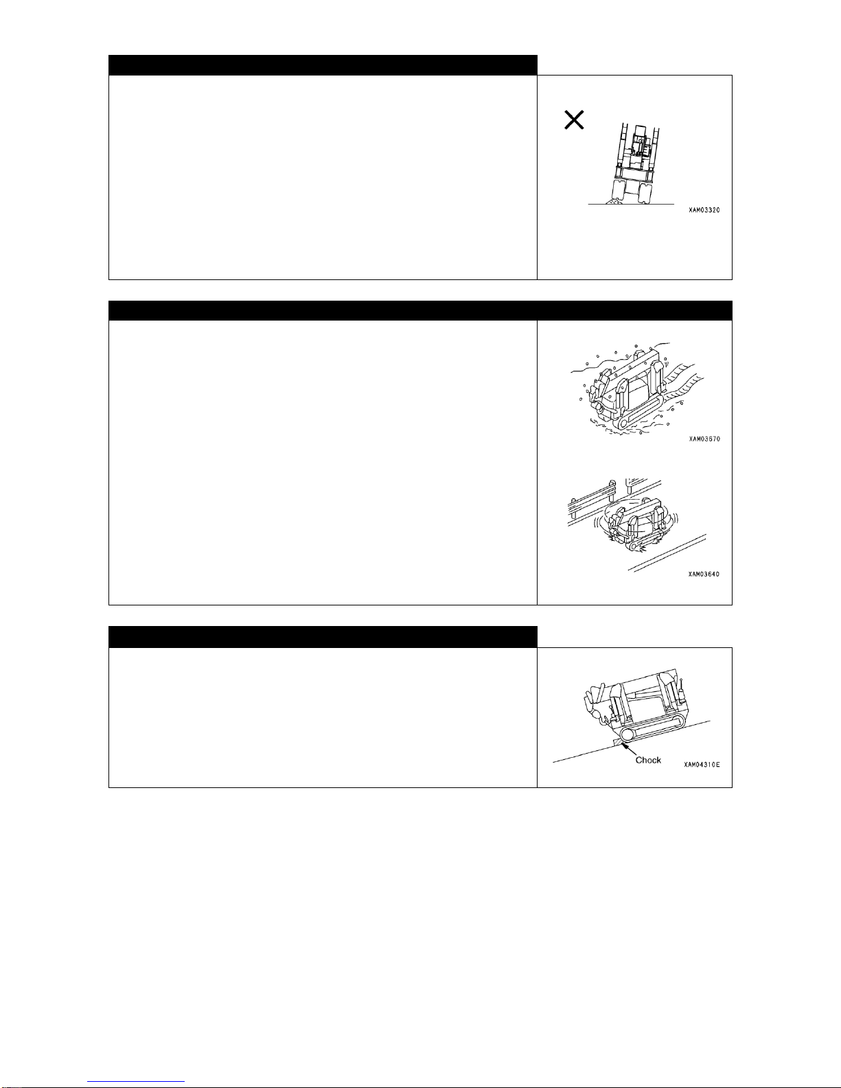
BE CAREFUL ABOUT TIPPING OVER ON UNSTEADY GROUND
In order to avoid serious injury or death, be sure to observe following rules
whenever you have to travel over unsteady ground:
When traveling on a slope, operator should always stand on upper side of the
machine.
・Do not enter soft ground. It may be difficult to escape.
・Do not approach precipice, shoulder, deep ditch because ground is
unsteady around there. Landslide due to mass or vibration of the machine
will cause the machine to tip over or fall down. Ground immediately after
heavy rain fall, blasting or earthquake will be prone to landslide.
・Over a banking or near an excavated ditch, ground is unsteady. Do not
approach where possible. Machine may incline due to its mass or
vibration.
RULES FOR ACCUMULATED SNOW OR FROZEN GROUND SURFACE
In order to avoid serious injury or death, be sure to observe following rules
whenever you have to travel over accumulated snow or frozen ground
surface:
・Snow accumulated or frozen surface is slippery even with a small
inclination. Slow down and avoid making jerky start, stop or turn.
Particularly going up or down a slope is slippery and hazardous.
・Frozen surface becomes unsteady to travel the machine on.
The ground will become soft as the temperature rises.
・In a cold climate, before attempting to lift, check to see that the load is not
stuck to ground or anything else because of freezing. Attempting to lift a
load frozen to the ground or anything else without knowing, is dangerous.
・In cold climate, do not touch metal surface or the like with your bare hand or
finger. Touching metal surface of a machine in extremely cold climate may
cause your skin to freeze to metal surface.
・Remove any snow or ice deposited on your machine as it makes difficult to
read caution plates. Particularly, if deposited on boom it should be
removed without fail, as it may fall down.
RULES FOR PARKING
・For parking the machine, select flat surface without danger of falling rock,
land sliding or being flooded.
・When parking on slope, apply a chock to prevent the machine from rolling.
・For parking on road, place caution sign including flag, protection fence, flood
light or the like within the limit not to disturb traffic.
・Before leaving the machine, shutdown the engine. Be sure to keep the
engine key at designated location.
Page 29
2-11
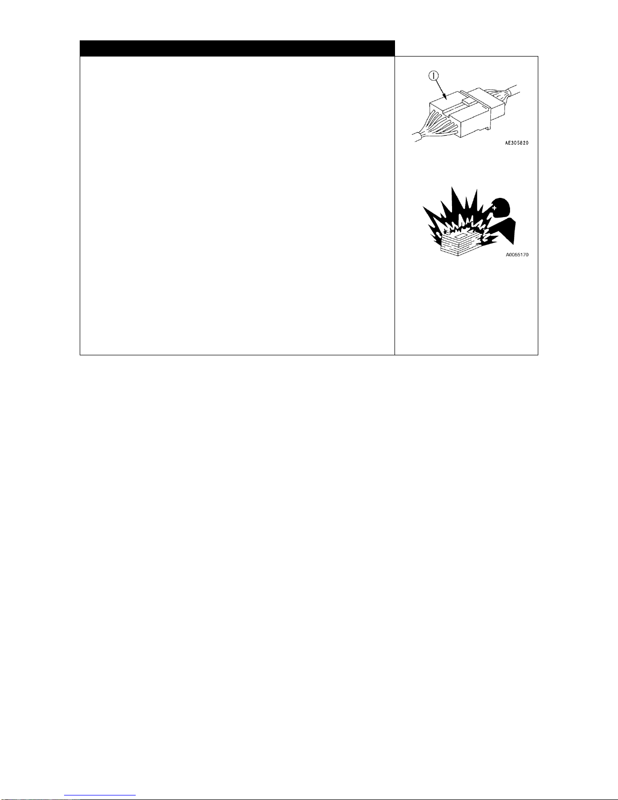
RULES FOR COLD CLIMATE
・After finishing work, wipe any water, snow or mud off the wire harness,
connector (1), switches and sensors before covering them. Freezing of
ingreassed water may cause the machine to malfunction, resulting in
unexpected accident.
・Remove or defrost snow or ice around swing gear, boom or winch and
make sure that they function properly.
・Conduct sufficient warm-up run. Without sufficient warm-up run, reaction of
the machine to control levers and switches will be slow, leading to
unexpected trouble.
・Rapid acceleration of the engine immediately after its start-up should be
avoided.
・Operate the control lever to relieve hydraulic pressure (raise the pressure to
exceed its set level so that hydraulic oil is released to its tank) to increase
temperature of oil in the circuit. This will improve reaction of machine and
prevents malfunctioning.
・When electrolyte is frozen, do not charge the battery or try to start up engine
with other battery. It may cause inflammation of the battery. Before
charging battery or starting up the engine using other battery, first defrost
the electrolyte and make sure that there is no leakage.
Page 30
2-12
2.3 DURING CRANE OPERATION
INSPECTION BEFORE STARTING YOUR WORK
Make sure that function of safety system and crane is normal.
・Operate control levers and switches at no-load and make sure that they function normally. If any abnormality is
detected, correct it immediately.
・Make sure that safety systems including over-hoist warning system function normally.
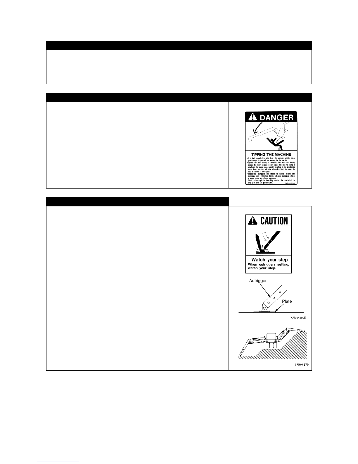
RULES FOR SELECTING LOCATION FOR PLACING OUTRIGGER FLOAT
For crane work, be sure to use the outrigger. Performing crane work without
outriggers set, may result in tipping over of the crane.
Be sure to place outriggers on level, hard and steady ground. Placing them
on following type of ground is hazardous:
・Random paved asphalt surface
・Thin concrete paved surface
・Stone paved surface
・Where underneath of pavement having been eroded by water to become
hollow, surface appears to be solid but inside is soft.
・Near any shoulder or hole for work.
・Inclined ground.
RULES FOR SETTING UP OUTRIGGER
In order to prevent accident of serious injury or death, for setting up outrigger,
observe following rules:
・When setting up outrigger, do not allow any person to approach. Serious
accident may result, such as your foot being caught by outrigger float.
・Except for extending or retracting outrigger cylinders, have the engine
shutdown, because if anyone inadvertently touches the outrigger switch,
the cylinder may be actuated unexpectedly and cause an accident.
・All the outriggers should be extended firmly. After having extended
outriggers, make sure that they are all well grounded.
・Over soft ground, use a plate under the outrigger floats.
・When you must set up outrigger near a shoulder, take every possible
measures to prevent collapsing of the shoulder.
・Outrigger should be set up while checking with leveling instrument so that
the levelness of machine is secured. During crane work as well, the
leveling instrument should be referred to once in a while in order to
maintain the levelness of machine.
・For working on slope, be sure to have the ground under outrigger float and
track leveled before setting up the outrigger. Setting up outrigger on
inclined ground without having it leveled, may cause the machine to
becomes unstable.
Page 31
2-13
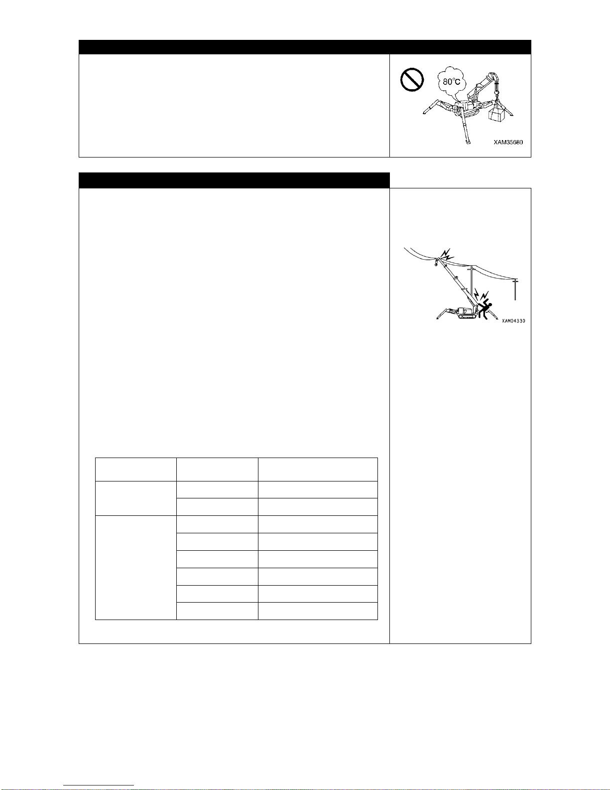
CAUTIONS HIGH TEMPERATURE OIL WHEN WORKING WITH CRANE
When hydraulic oil temperature exceeds 80 degrees, high pressure hoses
and seals can be damaged by heat, and it may cause burn by spouted oil.
If temperature of hydraulic oil becomes over 80 degrees, stop operation and
wait until the oil cools down.
Continuous hook raising / lowering operation at high working lifting height and
a long time accelerated operation are easier to raise oil temperature.
Especially be careful for these operations.
WATCH OUT FOR OVERHEAD POWER LINE
・Do not allow the machine to touch overhead power line. If it is high tension
line, electrification may result by just approaching.
・Observe following rules in order to avoid accident:
・At any job site where there is a possibility of boom or wire rope contacting
power line, discuss with the power company or make sure that measures
set forth in related regulations (such as placing a guard, sheathing the line
or posting caution board) have been taken, before starting the work.
・Wear rubber soled shoes and rubber gloves and be careful not to allow any
portion of your body which is not protected by rubber or the like to come in
contact with boom, wire rope or machine.
・Place a guide to watch for the boom, wire rope or machine not to approach
too closely to the power line. Sign for emergency should be established
beforehand.
・Inquire about voltage of power line at job site.
・Be sure to keep following distance between the boom, machine and power
line:
Power line
voltage
Minimum safety distance
Low voltage
(Distribution)
100・200V
2m
6,600V
2m
Special voltage
(Transmission line)
22,000V
3m
66,000V
4m
154,000V
5m
187,000V
6m
275,000V
7m
500,000V
11m
Page 32
2-14
PAY ATTENTION TO WEATHER INFORMATION
・When there is any possibility of lightning, discontinue crane work, ground the load immediately and retract the
boom.
・When load sways due to wind, the machine becomes unstable. If such is the case, ground the load immediately
and retract the boom.
・When the maximum instantaneous wind velocity reaches 10m/s, discontinue the crane work, ground the load
and retract the boom.
・Even when the maximum instantaneous wind velocity is less than 10m/s, the greater the lifted load, the higher
the load is lifted or the longer the boom, the greater the influence of wind. Work should be carried out with
sufficient caution.
・When lifting any load having wide area being exposed to wind such as steel plate, wind from front, rear or side of
boom can cause tipping of the machine or damage to the boom. Sufficient attention should be paid.
* In case of earthquake, suspend your work and wait until it settles down. Chart below is the guide of wind velocity
and its effect. Wind velocity in weather information represents a mean velocity (m/s) for 10 minutes at 10
meters above ground.
RULES FOR WIRE ENGAGING
・Before lifting load, make sure of the following: Lifting load without checking, may result in serious accident of
injury or death by falling of the load or tipping over.
・Observe values in total rated load chart.
・Lift at the center of gravity of load.
・Make sure that wire rope for hook block is in perpendicular.
・After lifting off the ground, stop hoisting the load once to make sure that the load is stable.
・Before lifting wired load, be sure to check that wire rope holding device at hook block is securely in place. If not,
wire rope may come off the hook block, causing serious accident with the load falling.
・When the angle of wire rope while lifting a load is great, even with the load of same weight, the load applied to
the rope will be greater and can break the rope. Wiring work should be performed with careful attention paid so
that wire rope is not exposed to unreasonable force.
・Lifting a long shaped load is dangerous as the load is unstable. In such case, lift it vertically with connect ropes
to each end of the load for improvement of stability.
Wind velocity (m/s)
Effect of wind
Up to 0.3
Quiet breeze. Smoke rises straight up.
0.3 - 1.6
Direction of wind can be known as it streams but anemoscope dose not detect it.
1.6 - 3.4
Wind felt by face. Leaves move constantly and anemoscope starts actuating.
3.4 - 5.5
Leaves and twigs moves constantly. Light weight flag opens.
5.5 - 8.0
Dust rises, small piece of paper flies and twigs move.
8.0 - 10.8
Shrub with leaves starts to rustle. Wave crest develops in lakes and marshes.
10.8 - 13.9
Big branches move. Power line howls. Hard to use umbrella.
13.9 - 17.2
Entire tree sways. Hard to walk against headwind.
17.2 - 20.8
Branches break. Impossible to walk against headwind.
20.8 - 24.5
Slight damage incurred by residential house. (Chimney falls and roof tiles come off)
24.5 - 28.5
Not frequently experienced inland. Trees uprooted. Major damage to houses.
28.5 - 32.7
Scarcely experienced. Destruction in broad region incurred.
Page 33

2-15
STANDARD OF WIRE ROPE REPLACEMENT
Be sure to observe the ISO 4309: 1990 (E) and the regulation to the area where operations are conducted when
replacing wire rope.
RULES FOR CRANE OPERATION
・Any work beyond the capability of machine will be a cause for serious accident including tipping over or
breakage or any other trouble. Perform crane work in accordance with the total rated load chart.
・Never travel with any load lifted. Crane may tip over resulting in serious accident of injury or death.
・Be sure to operate slowly. Sudden operation of lever or accelerator may cause a load to sway, fall or collide into
surroundings. Swing motion in particular should be performed at low speed.
・There is a danger of load falling or contacting which may lead to serious accident of injury or death. Do not allow
any person to enter inside the working radius or underneath the load. Working radius increases due to bend of
boom as a load is lifted, which should be taken into account.
・Crane work in poor visibility or bad weather is dangerous. In dark area, use flood light or other lighting system to
secure brightness. If view is poor due to bad weather (rain, fog, snow, etc.), discontinue your work and wait for
weather to improve.
・Do not use the crane for any duty other than its primary usage, such as lifting worker with it.
・Crane work should only be started after turning ON the over-hoist alarm switch. Whenever the hook block is
over-hoisted the warning buzzer will sound to notify you.
・Crane work should be started only after over-hoist preventive device switch is turned ON. When hook block is
excessively hoisted, buzzer will sound for warning.
・When the buzzer of over-hoist preventive device sounds, take your hand off the winch lever immediately.
Hoisting of the hook block will stop. Then, operate winch lever to Lower position (push forward) of the hook
block.
・As you extend the boom, the hook block will be hoisted. Therefore, when you extend the boom, keep lowering
the hook block by pushing the lever forward.
・If during work, overloading should take place, lower the load by pushing winch lever forward. Rapid hoisting or
lowering of the boom should be avoided because it may cause an accident by tipping over.
・Volume of hydraulic oil in each cylinder will vary as its temperature changes. If you leave the machine stopped
with a load suspended, the oil temperature will drop as the time elapses and as the volume reduces, hoist angle
or length of the boom will also be reduced. If such is the case, correct it by performing action for boom derrick or
extension appropriately.
・Do not leave operator seat, leaving a load suspended. If you have to, be sure to lower the load.
・When not in use, have the hook block wound up to prevent any person from colliding with empty hook block.
Page 34
2-16
RULES FOR OPERATING THE WINCH
・Do not allow any person to enter under a lifted load.
・When lifting a load, be sure to stop it at a point where the load is off the
ground to check for stability of the load and safety of weight before
continuing to lift.
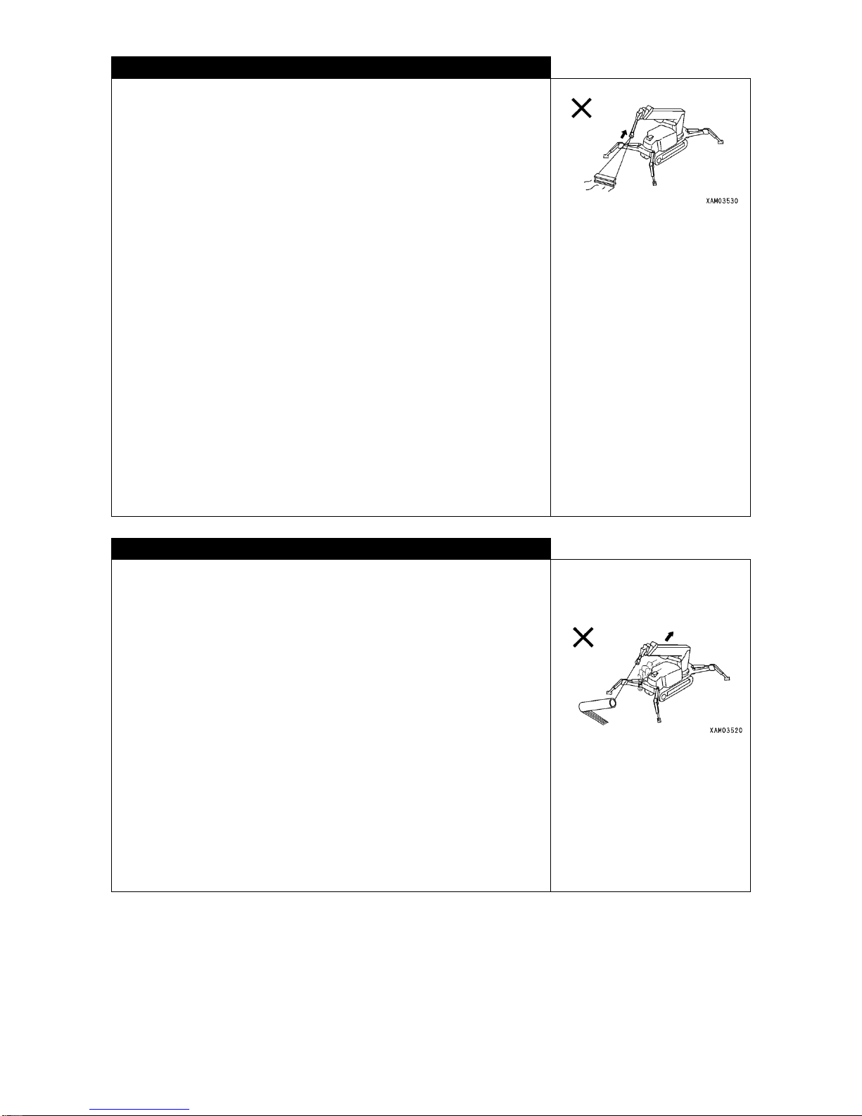
・Dragging laterally, pulling in or lifting at an angle to the load is prohibited.
Crane may tip over or be damaged.
・Hoisting the hook block excessively may cause the block to collide into
boom, break the wire rope and cause the hook block and load to fall down,
leading to a serious accident. Use sufficient care not to over-hoist the hook
block.
・Lift a load while using care not to allow wire rope or lifted load to contact with
obstacle such as tree or structure. If entangled with obstacle, do not
attempt to hoist forcibly but disentangle it first before continuing to lift.
・Do not use disorderly wound wire rope off the winch drum. Leaving this
rope wound disorderly on drum not merely shortens the useful life but can
break the rope causing serious accident. Observe following rules to
prevent wire rope from being wound disorderly:
・Do not ground the hook block.
・When lowering the hook block below ground level for underground work or
the like, be sure to leave minimum of 3 windings of the rope on winch
drum.
・When hook block rotates with the rope twisted, remove such twist
completely before resuming your work.
* See “OPERATION, 4.2 MEASURES TO TAKE WHEN WIRE ROPE IS
TWISTED”, for detail.
RULES FOR OPERATING THE BOOM
・Operate the boom control lever as slowly as possible. In Particular, rapid
lever operation with a load lifted will cause the load to sway and give
machine a big shock, resulting in damage to the crane or tipping over of
the machine.
・ Lowering the boom causes working radius to increase but the
corresponding total rated load to reduce. To perform your work while
hoisting or lowering the boom, use sufficient care so that the mass (weight)
of the load with the boom lowered to the lowest angle does not result in
overloading.
・Dragging laterally or pulling-in a load with boom derricking/lowering or
telescoping is strictly prohibited.
・When you telescope the boom, pay attention to the hoisting move of hook
block.
・Telescoping of the boom should be done carefully while making sure that
the hook block is being hoisted or lowered o Extending the boom causes
working radius to increase but the corresponding total rated load to reduce.
To perform your work while telescoping the boom, use sufficient care so
that the mass (weight) of the load with the boom extended to the maximum
does not result in overloading.
Page 35
2-17
RULES FOR MAKING SWING MOTION
・Before swinging, check for safety of surrounding and sound horn.
・Swing lever should be operated as slowly as possible. Start smoothly and
swing at low speed before stopping softly. Rapid lever operation with a
load lifted will cause the load to sway and the balance of machine to be
lost, which may result in damage to or tipping over of the crane.
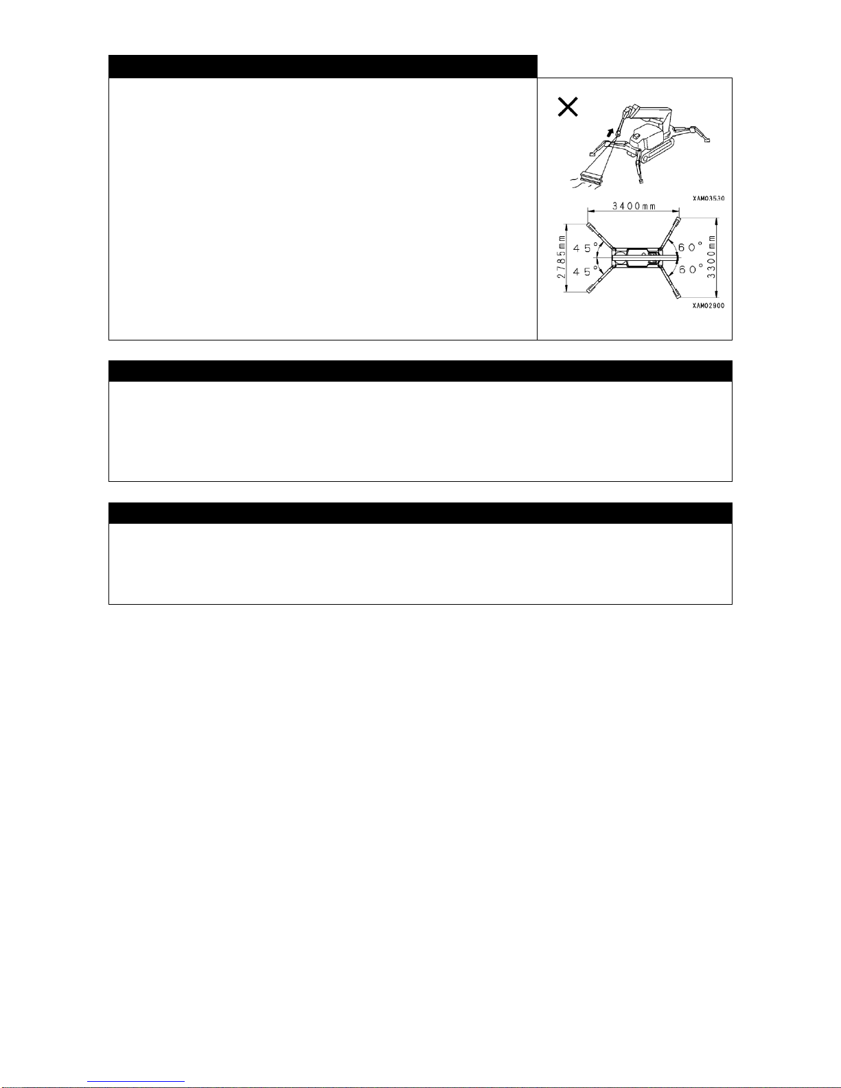
・Dragging in or erecting a load by means of swing motion is strictly
prohibited.
・For swinging 360 degrees with a load lifted, be sure to place outriggers in
the standard pattern as shown in the sketch to the right. In any
configuration other than this, you are not supposed to make 360-degree
swing. Further, you should remember that, even with the outriggers placed
to the maximum extension, lateral stability is not necessarily perfect.
・For lifting a load or making a swing, be careful so that wire rope or lifted load
does not contact with obstacle such as tree, steel structure or the like. If
entangled with obstacle, do not force to hoist the load but disentangle it
first.
RULES FOR MULTIPLE LIFTING
Multiple lifting may cause the center of gravity to shift and result in serious accident such as tipping over of crane,
falling down of load, and break down of crane.
Be sure not to implement multiple lifting two cranes or more.
In the event that multiple lifting is not prohibited by regulations in the area where operations are conducted and
operators are obliged to use two cranes or more because of either environments or requirements, observe the
following rules on their own responsibility.
WORKING FOR A LIFTING HEIGHT WHICH INVOLVES BELOW GROUND LEVEL
・For winching wire rope in below-ground-level work, be sure to leave at least 3 windings of rope on the winch
drum.
・Let every one understand signs in use.
・Operate crane with particular carefulness.
Page 36
2-18
3. RULES FOR TRANSPORTING A CRANE
RULES FOR LOADING TO AND UNLOADING FROM TRUCK OR TRAILER
・Loading and unloading involves a lot of danger. Particular care should be
used.
・Select level and hard ground for loading and unloading. Secure plenty of
distance from shoulder.
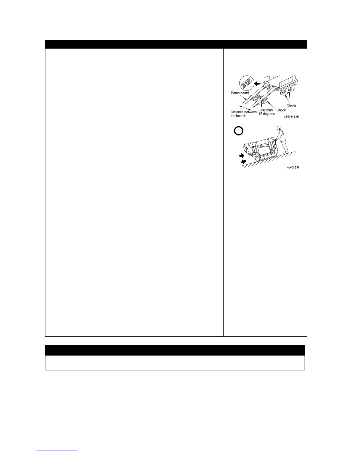
・Angle of ramp board should be less than 15 degrees. Set the distance
between the boards to match the track centers.
・For loading or unloading of the crane, be sure to let the crane assume
“Travel position” with position pins (4) securely inserted at the rotary.
* See “OPERATION, 2.5 TRAVEL POSITION OF THE MACHINE”, for
detail.
・Be sure to load the machine by traveling backward. Loading by traveling
forward may cause tipping over.
・Be sure to unload the machine by traveling forward Unloading by traveling
backward may cause tipping over.
・For loading or unloading, run the engine at idling speed and drive the
machine at low speed.
・Use ramp board having sufficient strength in terms of its width, length and
thickness for safe loading and unloading operation.
・To avoid side skidding of the machine on ramp board, remove dirt off the
undercarriage. Also keep the board clean with any deposit of grease or oil
removed. Be extra careful on rainy days as it gets slippery.
・Never correct traveling course on the board. If you want to, let the machine
get off the board to change the direction.
・For changing direction on truck bed, operate slowly because foothold is
unsteady.
・After loading, engage chock and lock the machine securely with wire rope
or the like.
* See “OPERATION, 5.1 LOADING AND UNLOADING PROCEDURE”,
for detail.
* See “OPERATION, 5.3 RULES FOR LOADING THE MACHINE”, for
detail.
RULES FOR TRANSPORT
When transporting the machine, follow local rules and regulations.
Page 37
2-19
RULES FOR LOADING AND UNLOADING BY MEANS OF A CRANE
Observe following rules for loading and unloading the machine with a crane
in use:
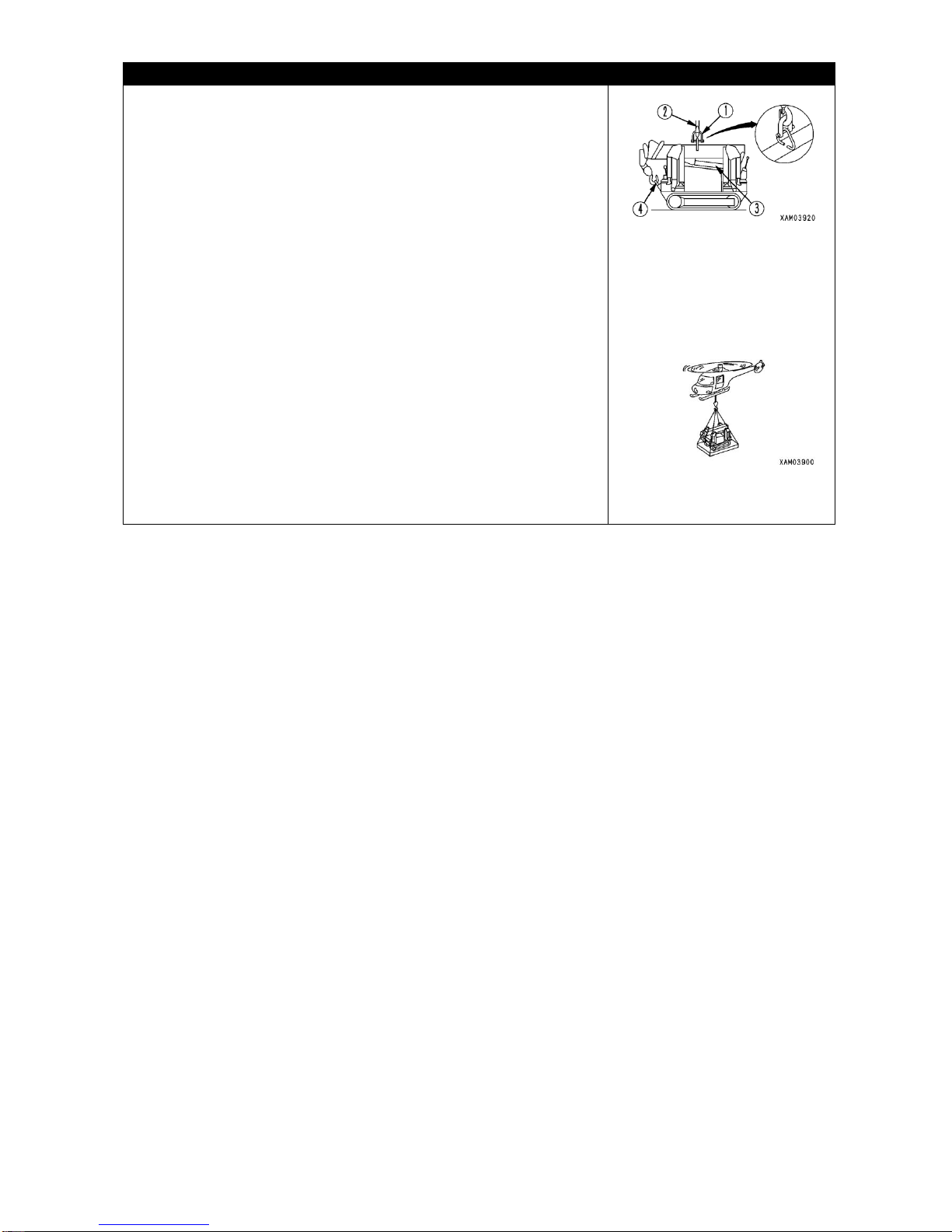
・For lifting up the machine, either engage the hook (2) of the lifting crane to
the hanger bracket provided on top surface of the boom or use a hanging
device (1) for engaging such hook (2).
・The crane and hangers (1) (wire ropes, shackles, etc.) for lifting duty should
be sufficiently strong for the mass (weight) of the machine.
・For lifting up the machine, be sure to let it assume travel position. Location
of center of gravity of the machine is established with the machine in travel
position. Also, for letting the machine assume travel position, make sure
that hook block is engaged to prescribed position and rope is tightened
sufficiently to prevent boom derrick cylinder from extending.
* See “OPERATION, 2.5 TRAVEL POSITION OF THE MACHINE”, for
detail.
・Holding the machine suspended for long time, may cause the boom derrick
cylinder (3) to extend, putting the machine out of balance with the center of
gravity shifted. Duration of suspension should be limited to about 10
minutes.
・For suspending the machine for long time (over 10 minutes) or moving it
with helicopter, use such hanger as shown to the right for the safety.
Page 38
2-20
4. RULES FOR HANDLING THE BATTERY
RULES FOR HANDLING THE BATTERY
Electrolyte contains dilute sulfuric acid and it generates hydrogen gas as well.
Its improper handling may result in injury or fire.
Observe following rules:
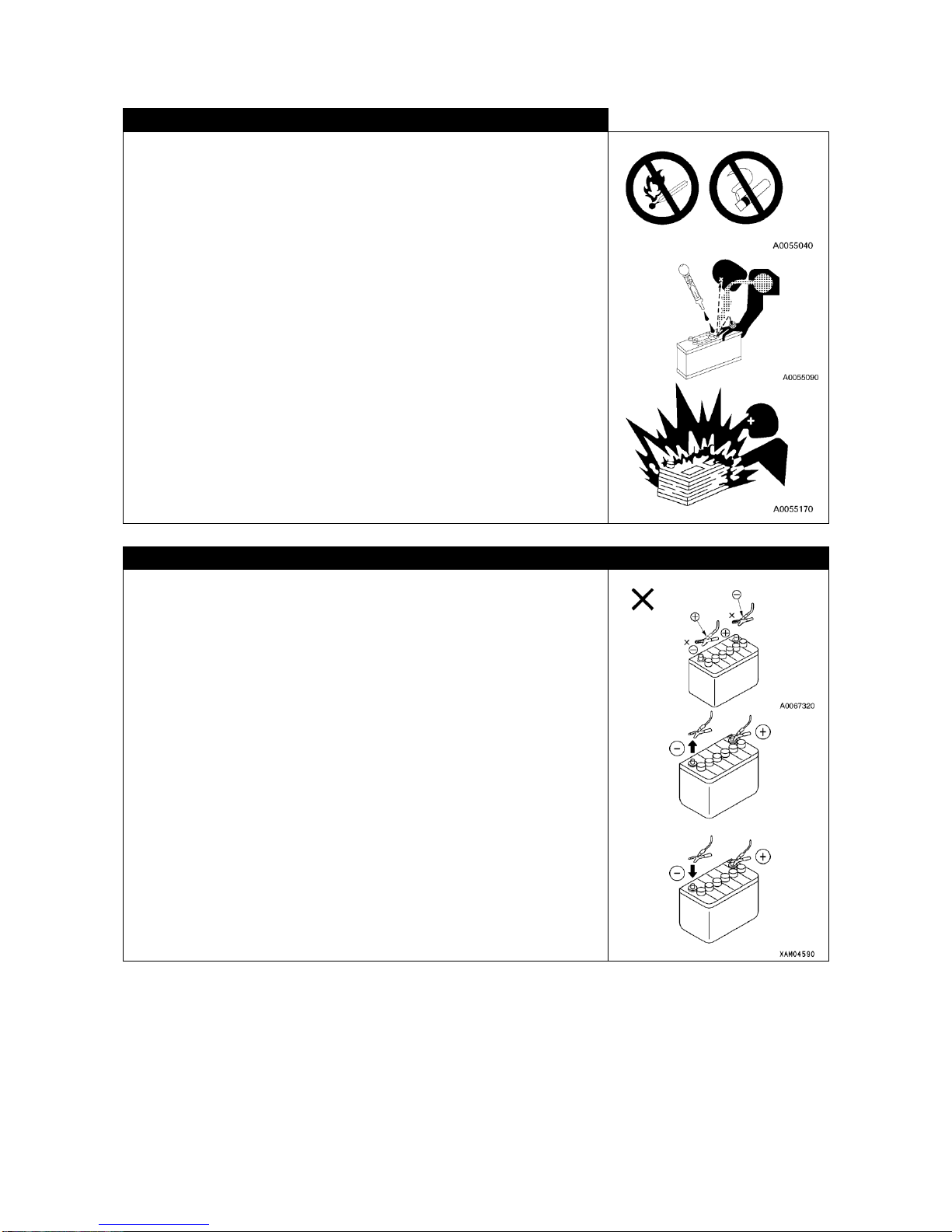
・Do not allow any fire including lighted cigarette to approach battery.
・For handling battery, be sure to wear goggles and rubber gloves.
・If electrolyte gets on your clothing or skin, wash it away with plenty of water
immediately.
・If electrolyte gets in your eyes, wash it away and see doctor promptly for
treatment.
・If you swallow electrolyte inadvertently, drink plenty of water, milk, raw eggs
or vegetable oil and see doctor immediately.
・Clean the top of battery with wet and clean cloth. Use of organic cleanser
such as gasoline or thinner is prohibited.
・Tighten battery caps securely.
・When electrolyte is frozen, do not charge or try to start engine with other
power supply. It may cause the battery to catch fire.
・For charging or starting engine with other battery in use, first defrost the
electrolyte and make sure it is not leaking.
・Before charging the battery, be sure to remove it from the machine.
RULES FOR STARTING THE ENGINE WITH BOOSTER CABLE IN USE
Improper connection of booster cables may cause fire. Observe following
rules.
・Engine should be started with 2 persons involved. One should be standing
on the operating position on the travel control panel side.
・For starting up the engine with other machine involved, make sure that two
machines do not come in contact with each other.
・Before connecting booster cables, starter switch keys should be turned off
on both of the normal and troubled machines.
・Booster cables should not be connected in opposite {(+) with (-) and (-) with
(+)}.
・Connection should be made with (+) terminal first and disconnected with (-)
terminal (ground connection end) first.
* See “OPERATION, 8.4 STARTING UP WITH BOOSTER CABLE IN
USE”, for detail.
・When disconnecting booster cables, avoid any contact between the cable
clips or between the clip and machine.
Page 39
2-21
RULES FOR CHARGING THE BATTERY
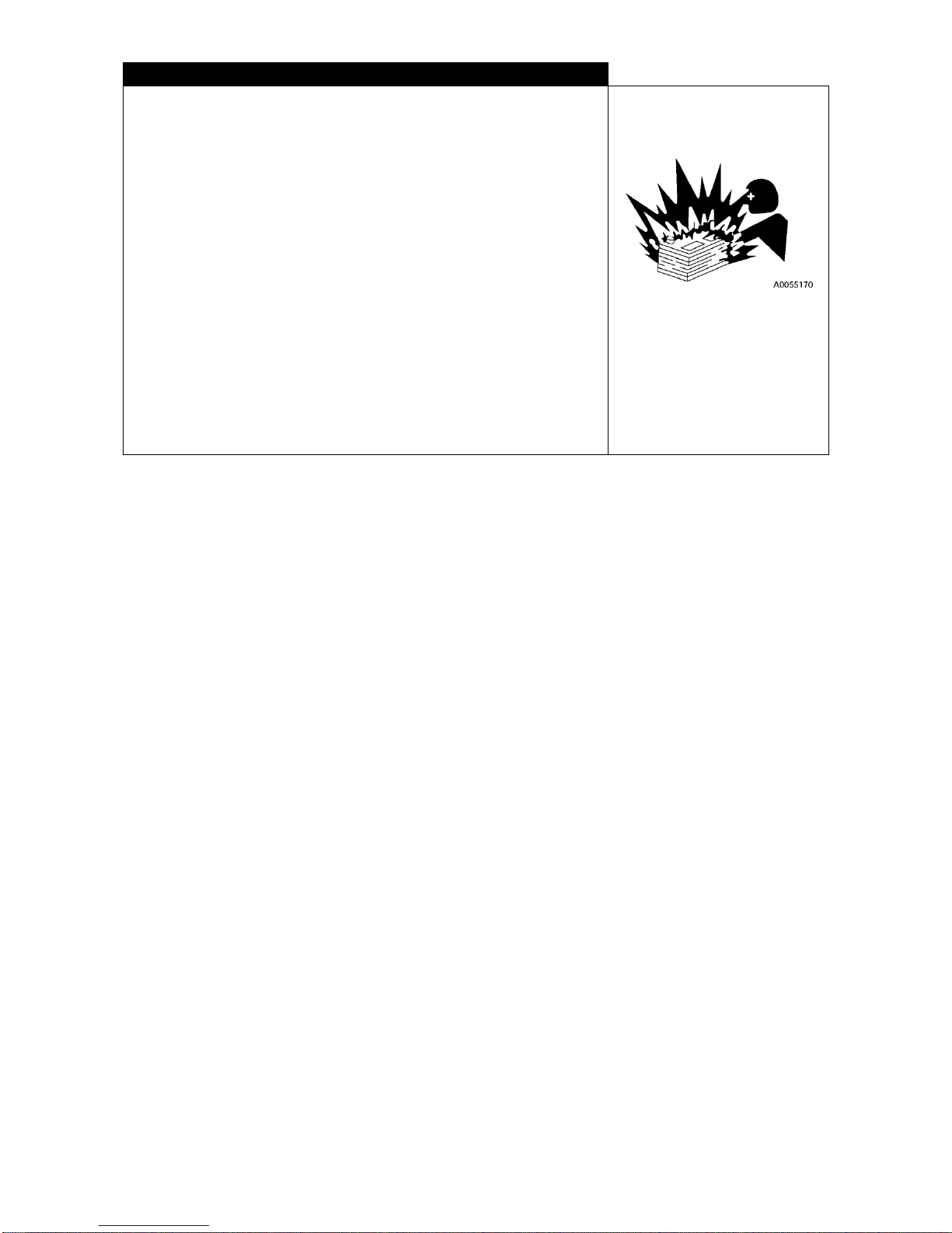
Battery can explode with its improper handling for charging. Follow the
direction provided in this manual as well as battery manual and observe the
rules shown below:
* See “OPERATION, 8.3 RULES FOR CHARGING THE BATTERY”, for
detail.
・Move the battery to well ventilated area and remove caps to allow diffusion
of hydrogen gas and prevent explosion.
・Adjust the voltage of charger to that of battery to be charged. Incorrect
voltage adjustment can result in overheating and explosion of the battery.
・Securely connect the (+) charging clip of the charger to (+) terminal of the
battery, before connecting (ミ) charging clip to (ミ) terminal of the battery.
・Charging current should be set to the value less than 1/10 of rated capacity
of the battery. In case of boosting charging, set it below the value of rated
capacity of the battery.
・Charging battery excessively may lead to inflammation and explosion with
electrolyte leaking or drying up.
Page 40
2-22
5. RULES TO OBSERVE IN CONNECTION WITH SERVICES
5.1 PRIOR TO CONDUCTING SERVICES
NOTIFICATION ON TROUBLE
Conducting any service that is not described in this manual may result in unexpected trouble. Notify your dealer
about it.
PROCEED WITH INSPECTION AND SERVICE ONLY AFTER CLEANING THE MACHINE
・Before conducting inspection and service, clean the machine to prevent
dust from entering and so that you can service safely.
・Inspection and service conducted with the machine remaining smeared will
not merely makes it difficult to detect deficiency, it will cause dust or dirt to
enter your eyes or you incur injury by slipping to fall.
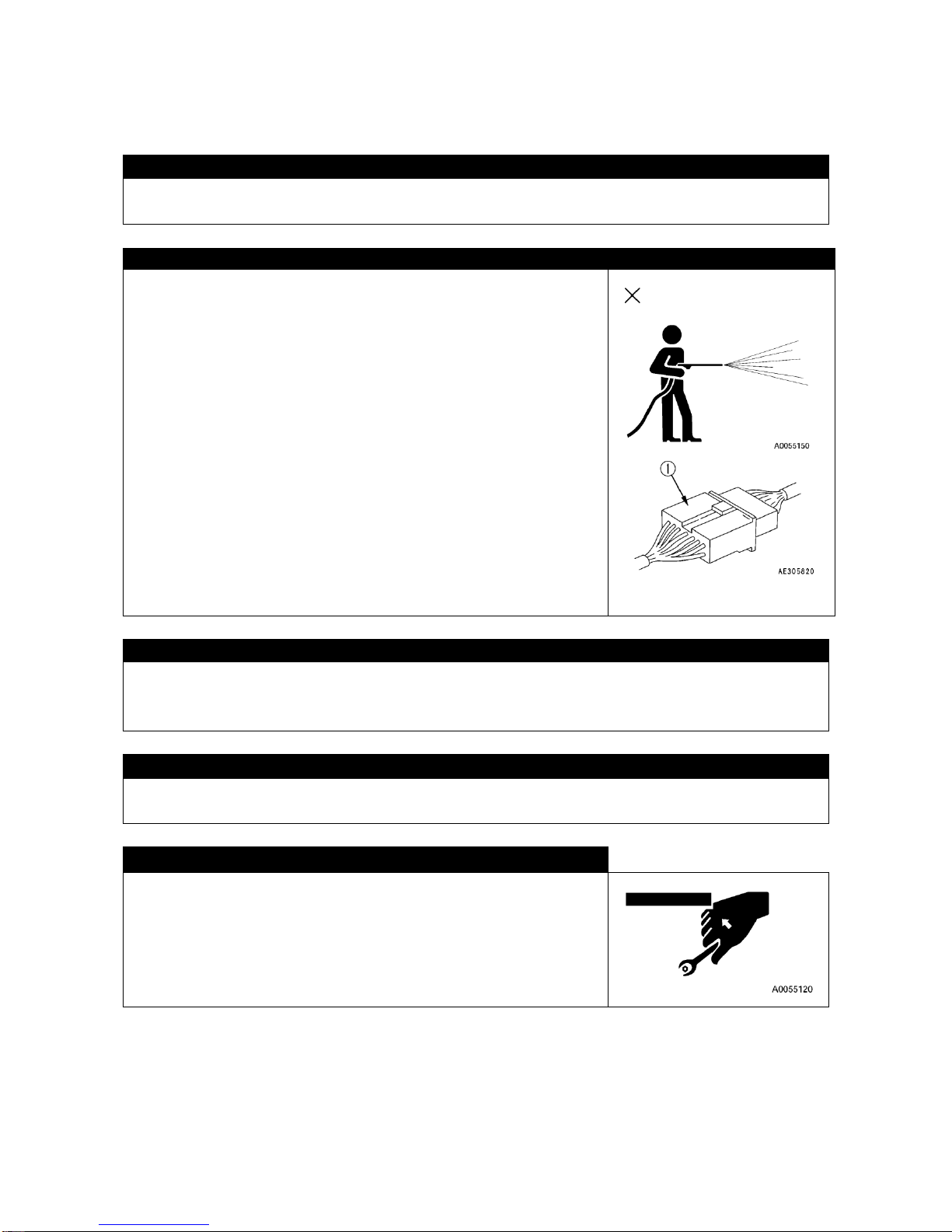
・For washing the machine, observe following:
・Wear slip proof shoes to prevent from slipping due to wet foothold.
・When using high pressure steam for cleaning, wear protectors. Avoid
accident of getting a cut or dirt entering your eyes by touching the high
pressure.
・Do not water electric systems (sensors, connectors, receiver boxes) (1).
Water entering electric system is hazardous as it causes actuation
deficiency, leading to malfunctioning.
KEEPING JOB SITE NEAT AND CLEAN
Keeping job site neat and clean. For your working safety, keep your job site clean by moving tools and hammers
out of your way and wiping off slippery grease or oil. Leaving job site disorderly will expose you to risk of
stumbling and slipping to incur injury.
JOINT WORK SHOULD BE PERFORMED UNDER DIRECTION OF LEADER
For performing machine repair or installation or removal of attachment, designate a leader and follow his or her
direction. Failure to understand command among joint workers can lead to unexpected accident.
USE PROPER TOOL
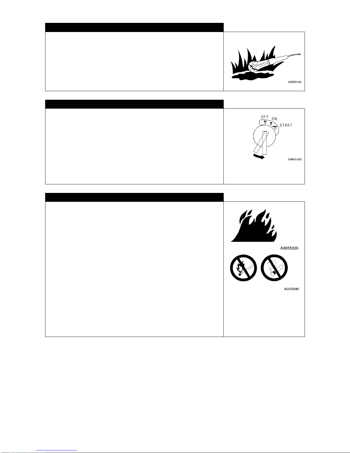
Do not use broken, deteriorated or wrong tool for your purpose. Chip of
rounded chisel or hammer can even blind you if it gets in your eyes.
Page 41
2-23
LIGHTING SYSTEM
・For checking fuel, oil or electrolyte, use lighting system of explosion proof
type. If not, an explosion may result.
・Working in dark area without flood light may lead to accident. Be sure to
use lighting properly. Just because it is dark, do not use fire of cigarette
lighter or the like in place of lighting. Fire or explosion due to inflammation
of electrolyte gas could result.
SHUTDOWN ENGINE FOR INSPECTION OR SERVICE
・For inspection or service, be sure to park the machine on level and hard
ground without possibility of falling rocks or land slide or being flooded, with
boom totally retracted and lowered and engine shutdown.
・Operate all the crane control levers back and forth for a few repetitions to
release residual pressure in hydraulic system.
・Apply chocks to rubber tracks to prevent the machine from rolling.
・Any service personnel should be careful so that his or her body or clothing
does not contact any moving part.
PREVENTION OF FIRE BREAKING OUT
During service work, dangerous object having risk of inflammation including
fuel or battery will be handled. Following should be strictly observed:
・Fuel, oil and grease should be stowed away from fire.
・Do not leave place of your duty during replenishment of fuel and oil.
・ For parts cleaning, use incombustible type of cleanser and avoid
inflammable light oil, gasoline or the like.
・Do not smoke while conducting inspection or service. Smoke at designated
area only.
・When inspecting fuel, oil or electrolyte, use explosion proof lighting and do
not use cigarette lighter or matches in place of lighting.
・Loosened or damaged ele ctric connection can cause fire by short circuiting.
Check it during pre-operation check.
Make sure that fire extinguisher is available in the vicinity of your place of
inspection and service.
Page 42
2-24
5.2 DURING SERVICE WORK
UNAUTHORIZED ENTRY PROHIBITED
During service work, do not allow any unauthorized person to enter.Place a guard as required. Use particular
care during grinding, welding or driving work.
ACTION TO TAKE WHEN ABNORMALITY IS FOUND DURING INSPECTION
・During inspection, if abnormality is found, be sure to correct it. Using the machine without correcting defect may
result in accident involving injury or death.
・Depending on the trouble involved, contact your dealer.
DO NOT DROP TOOL OR PARTS INTO THE MACHINE
・When carrying out inspection with access panel or filler port of tank opened, try not to drop bolt, nut or tool into
the machine. Dropping them may cause damage or malfunction of the machine, leading to accident. If you
should drop anything, be sure to pick it up.
・Do not leave anything in your pocket other than those required for the inspection.
BE CAREFUL ABOUT NOISE
High level of noise around you can cause you to incur difficulty in hearing or to be deafened. Be sure to use ear
covers or plugs during engine service or the like which exposes you to noise for long period of time.
SERVICE WORK WITH ENGINE RUNNING SHOULD BE PERFORMED WITH 2 OR MORE
PERSONS
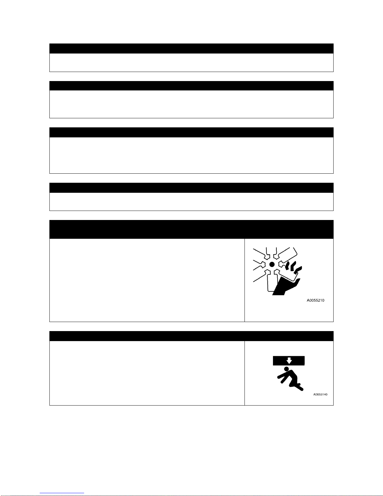
For avoiding accident, do not perform service work with engine running. If
inevitable, observe following:
・One person should stand at engine operating position on travel control
panel side so that at anytime he can stop the engine, and always keep
contacting each other.
・For working near any rotating part, use care because there is a risk of being
caught.
・Do not touch control levers. If inevitable, be sure to give the partner a signal
to let him or her evacuate from danger zone.
・Never touch alternator drive belt or the like with your body or tool because it
can result in amputation.
CARE TO BE USED WHEN WORKING UNDERNEATH THE MACHINE
・Park the machine on level, hard ground with boom totally retracted and
lowered.
・For performing service from underneath the machine, let the machine float
with outrigger extended to maximum. If the machine is unstable and
sways then, engage support under its front and rear for stabilization.
Page 43
2-25
CARE TO BE TAKEN WHEN WORKING ON THE MACHINE
・For service work on the machine, tidy up your foothold for prevention of
falling down and observe following:
・Do not spill oil or grease.
・Do not scatter tools around.
・Watch your steps when walking.
・Do not jump off the machine.
For mounting or de-mounting, use stool and support your body securely
with at three or more locations using your hand and foot (Both feet and
hand or both hands and foot).
・Use protector adequate to your work.
・For prevention of downfall or stumbling by slipping, do not get on boom,
outrigger or machinery cover.
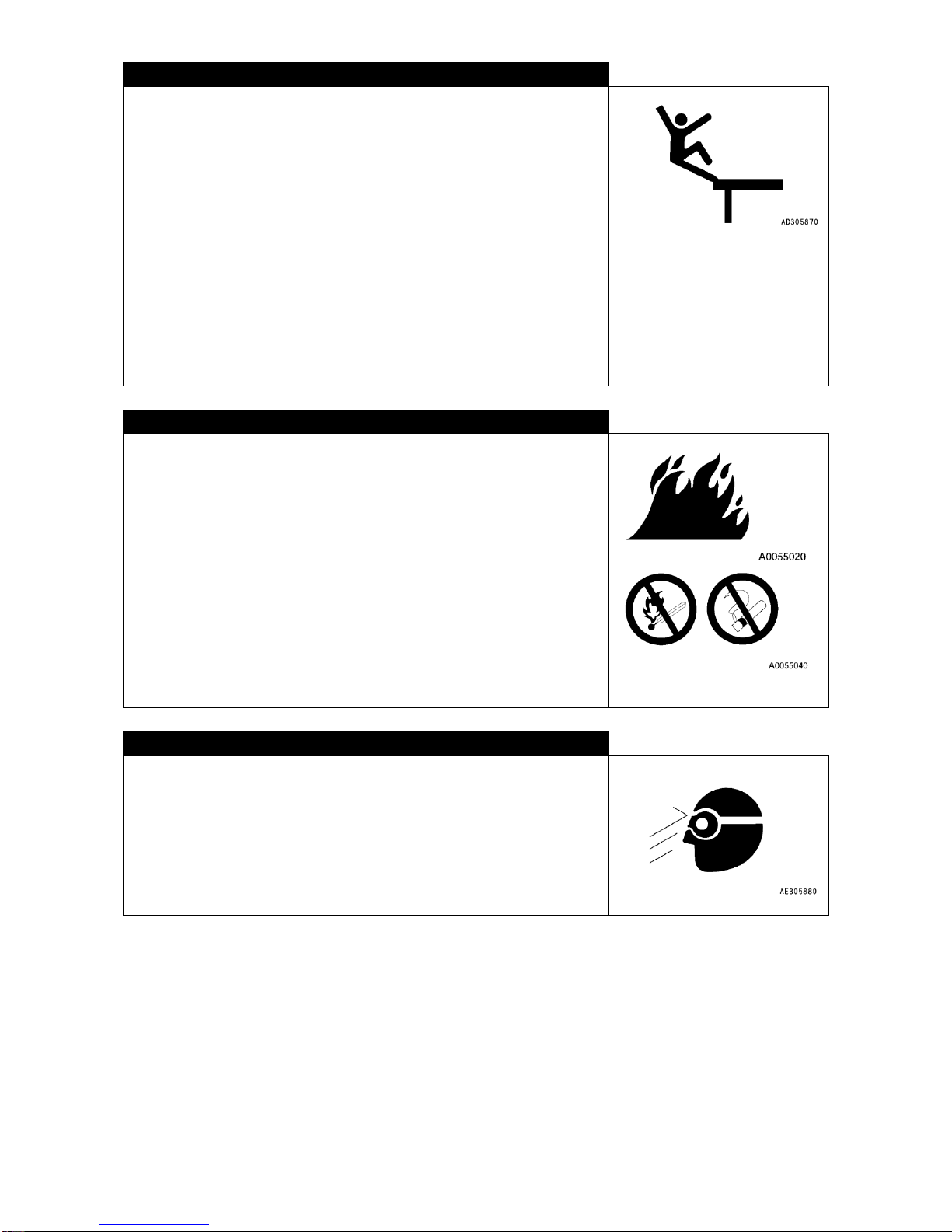
CARE TO BE TAKEN WHILE REPLENISHING WITH FUEL OR OIL
Fuel or oil may ignite when fire approaches to it.
Particularly gasoline being in use, observe following:
・Stop engine while replenishing.
・Do not smoke during replenishment.
・Wipe off any spilled fuel or oil immediately.
・Tighten fuel or oil cap securely.
・Carry out fuel or oil replenishing work at well ventilated area.
・Do not leave the spot during replenishment.
CARE TO BE TAKEN DURING HAMMER WORK
For hammer work, wear protector such as goggles or helmet and place brass
rod or the like between object and the hammer to blow.Giving impact to
hard metal parts such as pin or bearing, may cause its chip to get in your
eyes.
Page 44
2-26
CARE TO BE TAKEN DURING WELDING REPAIR WORK
Welding work should be performed at well equipped place by qualified person.
Welding work may cause generation of gas, fire or electrification. Non-qualified person should absolutely refrain
from doing it.
Qualified welding personnel should observe following:
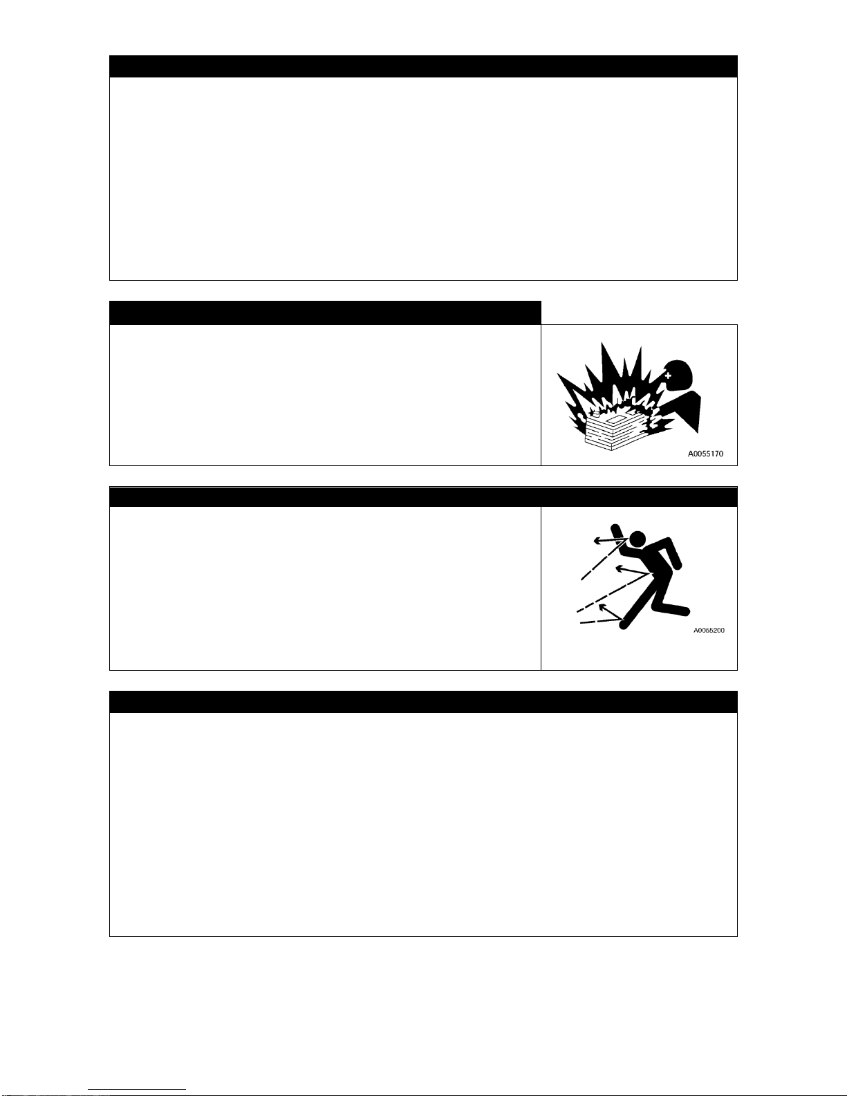
・For prevention of battery explosion, disconnect battery terminal.
・Any paint on welding area should be removed for prevention of gas generation.
・Heating hydraulic equipment, piping or rubber hose or its vicinity may cause inflammable gas or steam to ignite.
Avoid heating such area.
・Heating pressurized piping or hose directly may cause them to suddenly break. Use fireproofing sheath.
・Wear protector.
・Make sure to have good ventilation.
・Stow away any inflammable object and have fire extinguisher ready.
REMOVING BATTERY TERMINAL
For performing repair of electric system or welding work, disconnect negative
terminal of the battery to stop electric current.
* See “OPERATION, 8. HANDLING OF BATTERY”, for detail.
CARE TO BE TAKEN DURING RUBBER TRACK TENSION ADJUSTMENT
・Internals of rubber track tension adjust system is packed with grease, which
is highly pressurized with track tension. Attempting to remove grease in
negligence of following rules may cause the grease valve to blow off,
resulting in serious accident.
・Tension adjusting grease valve should not be loosened by more than one
turn. Grease valve may blow off otherwise.
・When adjusting the tension, do not position yourself directly in front of the
valve to avoid the risk.
* See “INSPECTION AND MAINTENANCE, 8.4 [3] RUBBER TRACK
TENSION INSPECTION AND ADJUSTMENT”, for detail.
HIGH PRESSURE HOSE: USE CARE
Leakage of oil from high pressure hoses may cause injury due to fire or malfunctioning of systems.
Whenever damage in hoses or loosened bolts are found, discontinue your work and contact your dealer for
repair.
・For replacement of high pressure hoses, skilled technic is required. Further, tightening torque has been
established according to type and size of hoses. Do not perform repair work by yourself.
・When situation such as follows is found, replace the relevant parts:
・Damage of or leakage at hose metal piece.
・Sheath worn or broken or wire reinforcement layer exposed.
・Partly expanded sheath
・Sign of twist or collapse at moving part of hose
・Foreign matter buried under sheath
・Deformed hose metal piece.
・Replacement should be made with one hose at a time to avoid error.
Page 45
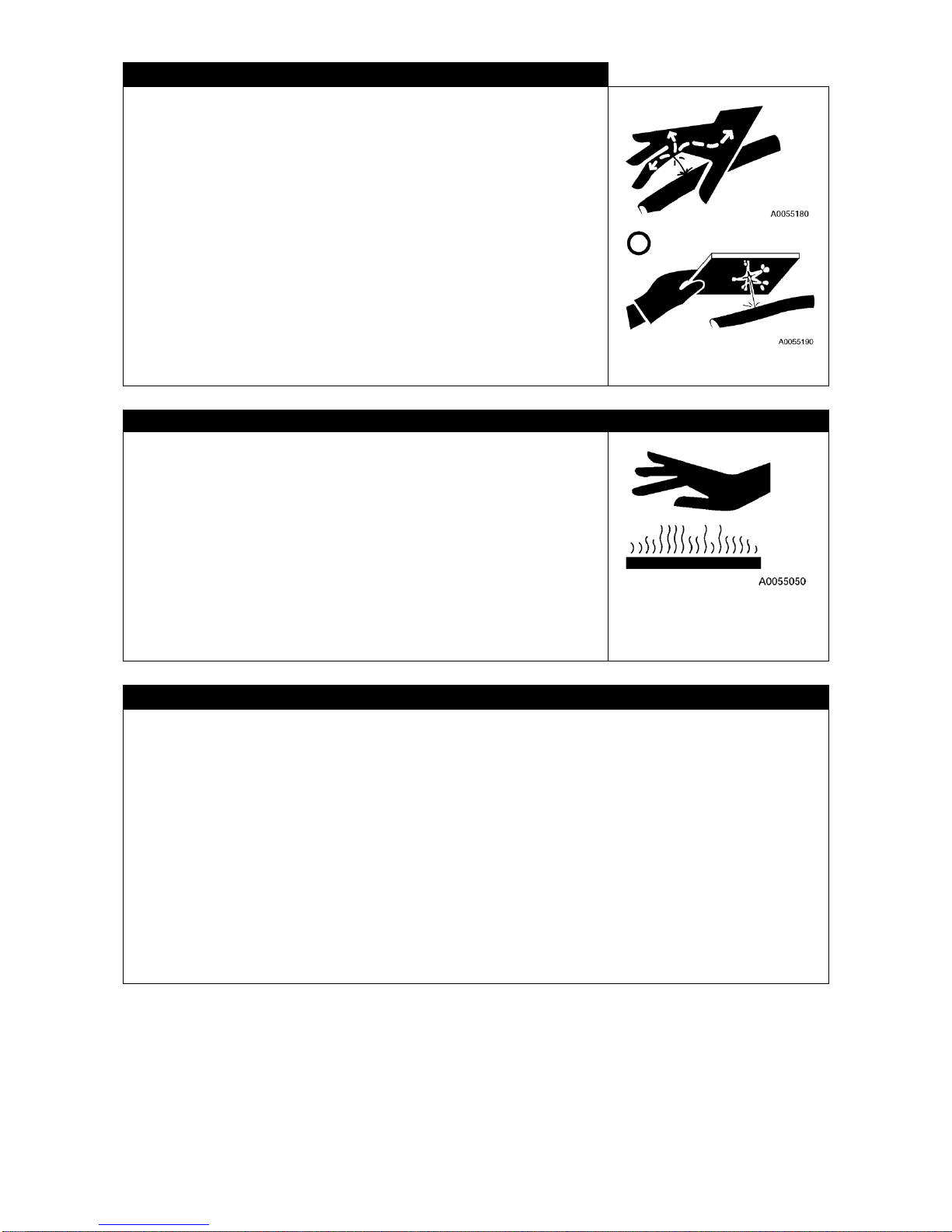
2-27
CARE TO BE TAKEN IN CONNECTION WITH HIGH PRESSURE OIL
When inspecting or replacing high pressure piping or hose, unless you make
sure that the pressure has been released, serious accident may result.
Strictly observe following:
・Do not proceed with inspection or replacement work before pressure is
eliminated.
・Wear protection goggles and leather gloves.
・If there is leakage in piping or hose, such piping, hose or its vicinity is wet.
Check for crack in piping and crack or expansion in hose.
If it is difficult to identify, be sure to contact your dealer for repair.
・Leakage of high pressure oil from any small hole can hit you and cut your
skin or make you blind.
If you incur serious injury on your skin or in your eyes with high pressure oil,
wash it off with water and see doctor promptly.
CARE TO BE TAKEN IN CONNECTION WITH HIGH TEMPERATURE
Immediately after engine is shutdown, engine, various oil, exhaust manifold
and muffler remain hot.
Performing service work under such condition, including removing cap or
replacing oil, water or filter will result in scalding. Wait for temperature to drop
before proceeding with service in accordance with procedures shown in this
manual such as follows:
* INSPECTION AND SERVICE, 8.5 PRE-OPERATION INSPECTION: for
inspection of engine oil and hydraulic tank oil level check.
* INSPECTION AND SERVICE, 8.6 SERVICE IN EVERY 50 HOURS: for
engine oil replacement.
* INSPECTION AND SERVICE, 8.8 SERVICE IN EVERY 500 HOURS: for
Hydraulic return filter replacement.
CHECKING TO BE PERFORMED AFTER INSPECTION AND SERVICE
Failure to complete the required service items or failure to verify the function or actuation of serviced location, may
cause unexpected trouble to occur, resulting in serious accident. Observe following strictly:
・Checking after stopping engine:
・Check for any neglected inspection and service location.
・Check for proper execution of required inspection and service.
・Check for tools or parts dropped. It is dangerous particularly if they are dropped internally or caught by link
mechanism of levers.
・Check for water leakage, oil leakage or bolt not tightened.
・Checking with engine running
For checking engine while it is running, see Paragraph メService work with engine running should be performed
with 2 or more personsモ and pay sufficient attention for your safety.
・Check the inspected and serviced location for normal actuation.
・See if oil leakage does not occur when engine speed is increased and load is applied to hydraulic system.
Page 46

2-28
CARE TO BE TAKEN ABOUT WASTE TREATMENT
In order to avoid polluting the environment of area where people and animals
live, observe following strictly:
・Do not dispose waste oil to sewerage system or river.
・Be sure to dispose oil from machine to container. Do not dispose it directly
to ground.
・For disposal of harmful matter including oil, fuel, solvent, filter and battery,
observe applicable laws and regulations.
Page 47
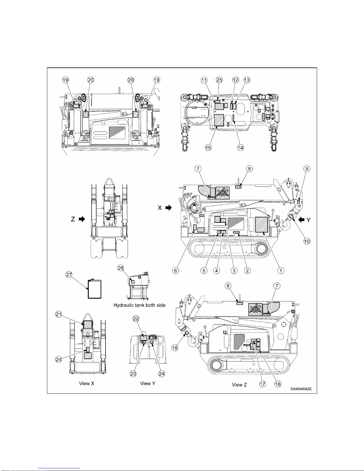
2-29
6. LOCATION FOR AFFIXING CAUTION PLATES
Keep these labels always clean. If it comes off, affix it again or replace with new one. There are other plates than
those shown below. Take care of them in the same manner.
Page 48
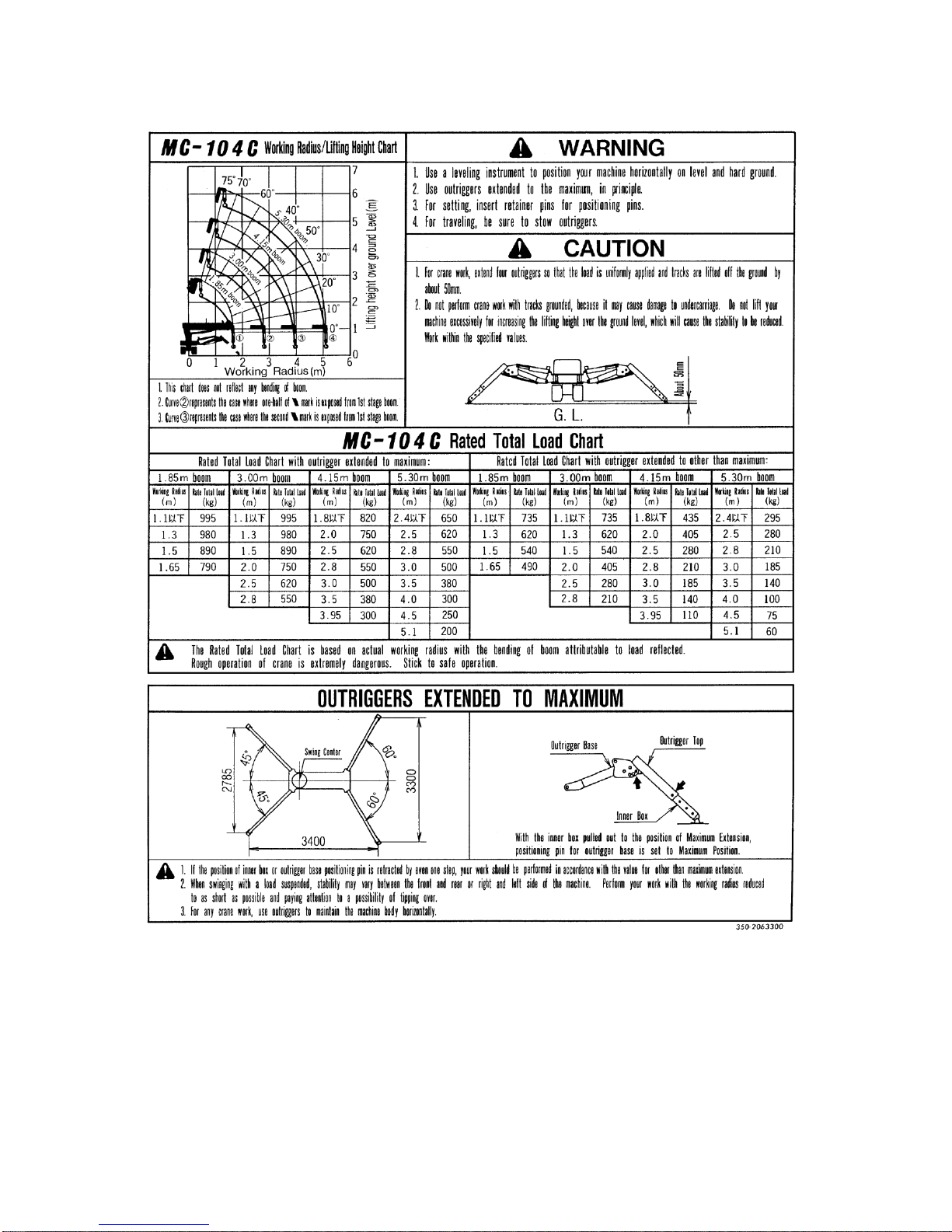
2-30
(1) Note for crane performance and outrigger. (350-2063300)
Page 49
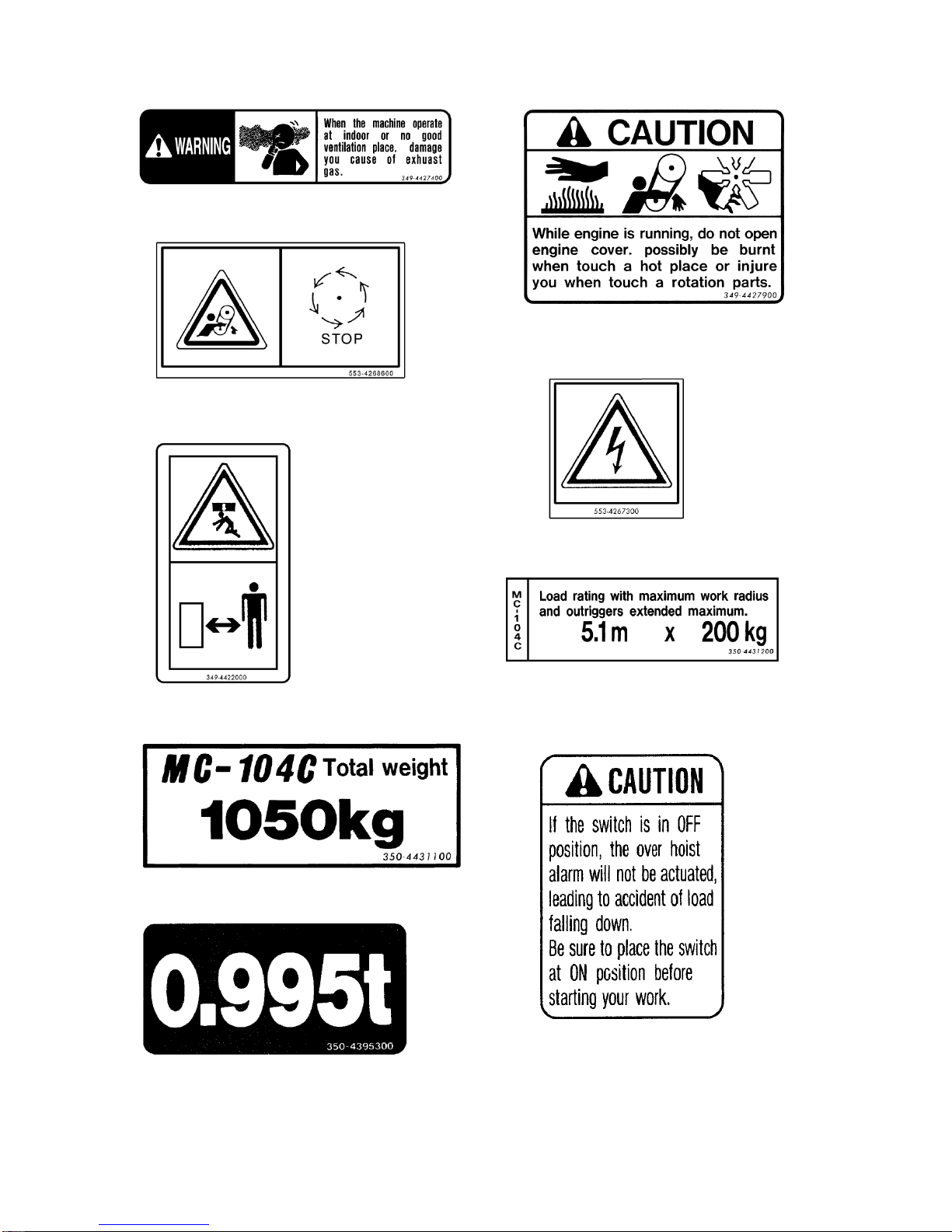
2-31
(2) Note for exhaust gas (349-4427400) (3) Note for engine cover (349-4427900)
(4) Precautions when open-close the cover (553-4268600)
(5) Warning for electric shock (553-4267300)
(6) Watch for crane approach (349-4422000)
(7) Minimum lifting load (350-4431200)
(8) Machine weight display (350-4431100) (9) Note for over-hoist alarm system (350-4431300)
(10) Crane load (350-4395300)
Page 50
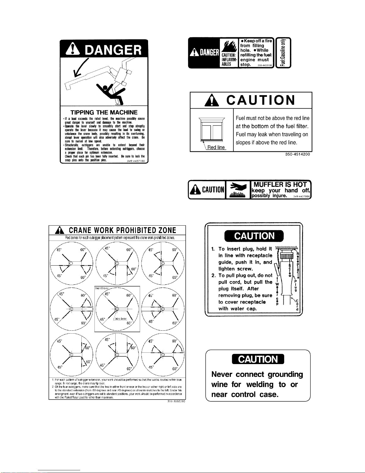
2-32
(11) Note for crane tipping-over (349-4427100) (12) Note for keeping away from fire (350-4433100)
(13) Note for refilling fuel amount (350-4514200)
(14) Note for muffler (349-4427800)
(15) Note for crane work prohibited zone (350-3252200) (16) Note for inserting plug (300-4214000)
(17) Note for welding grounding wire (300-4214200)
Page 51

2-33
(18) Precautions for rotating parts (553-4267400) (19) Note for out-rigger pin hole. (349-4426900)
(20) Note for outrigger (349-4427000) (21) Note for traveling on slope (350-4515600)
(22) Note for over-hoist alarm buzzer (350-4432100)
(23) Note for operation and service work (893-4239100)
(24) Note for main switch (349-4421400)
(25) Fuel tank cap caution (103-4604900) (26) High temperature
(553-4267700) (2 places)
Page 52
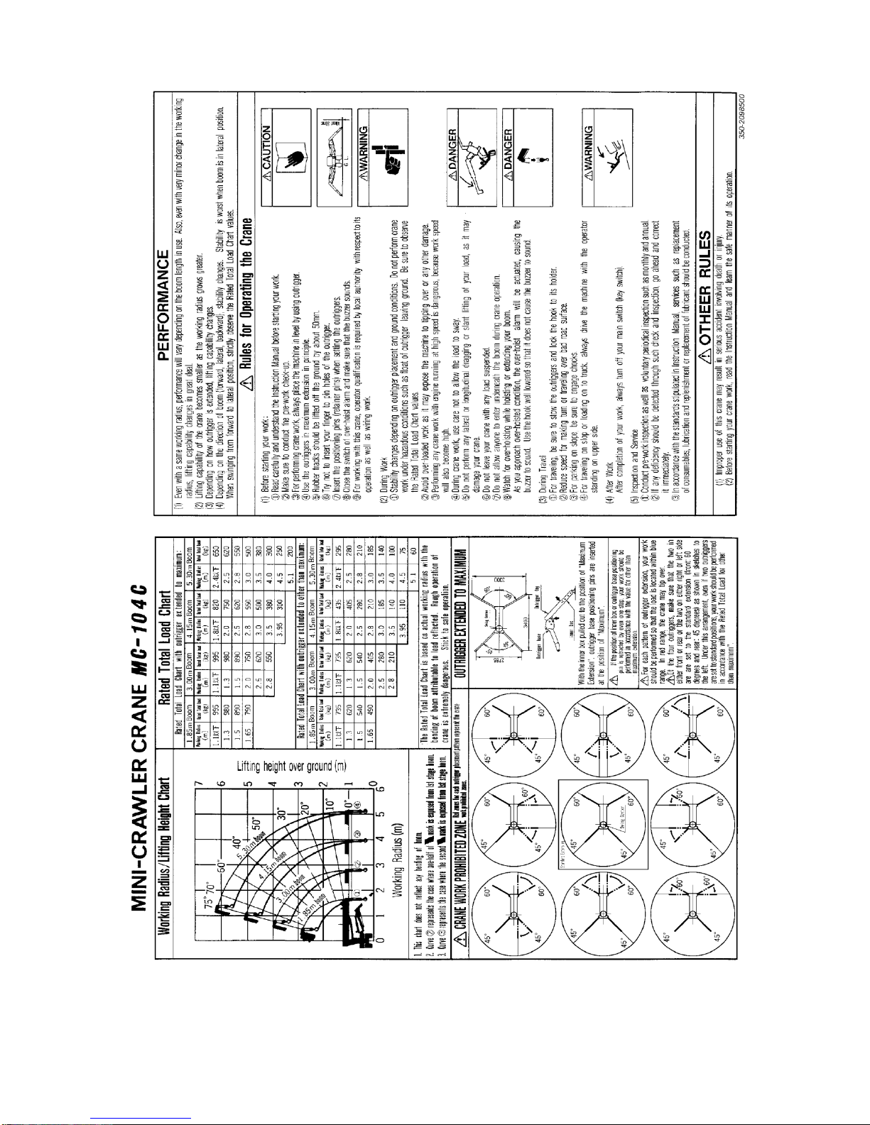
2-34
(27) General rules for use (Card type) (350-2098500)
Page 53

3-1
OPERATION
1. NOMENCLATURE OF COMPONENTS
3- 2
2. OPERATION CONTROL
3-15
3. HANDLING OF RUBBER TRACK
3-53
4. HANDLING OF WIRE ROPE
3-57
5. TRANSPORT
3-59
6. HANDLING IN COLD CLIMATE
3-62
7. LONG TERM STORAGE
3-63
8. HANDLING OF BATTERY
3-64
9. MEASURES TO BE TAKEN IN CASE OF ABNORMALITY
3-68
Page 54
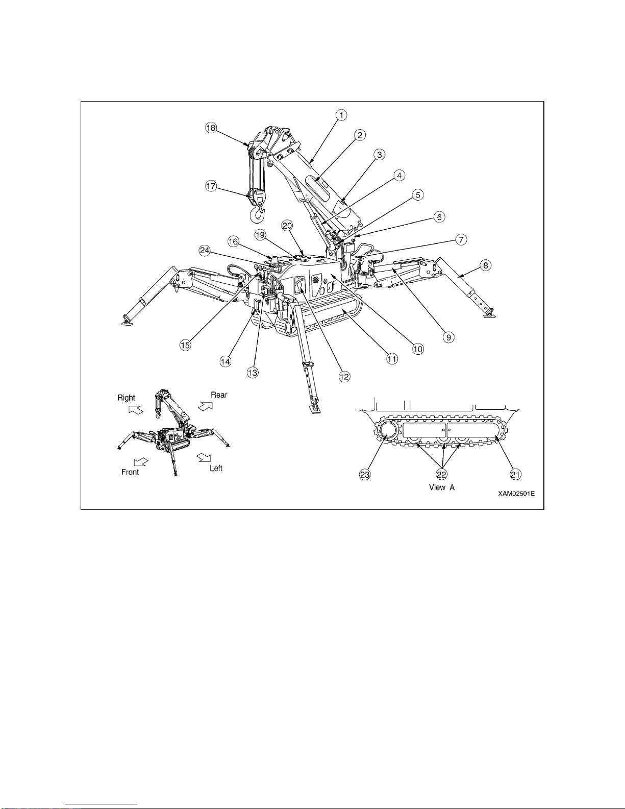
3-2
1. NOMENCLATURE OF COMPONENTS
1.1 NOMENCLATURE OF MACHINE COMPONENTS
① Boom
② Boom telescope cylinder
③ Load indicator
④ Boom derrick cylinder
⑤ Winch
⑥ Post
⑦ Travel control
⑧ Outrigger
⑨ Outrigger cylinder
⑩ Machinery cover
⑪ Rubber track
⑫ Engine
⑬ Flood light
⑭ Hook hanger
⑮ Crane control
⑯ Outrigger mode indicator lamp
⑰ Hook block
⑱ Over-hoist preventive device
⑲ Fuel tank
⑳ Hydraulic tank
K Rear idler
L Track roller
M Travel motor and sprocket
N EMO switch
Page 55
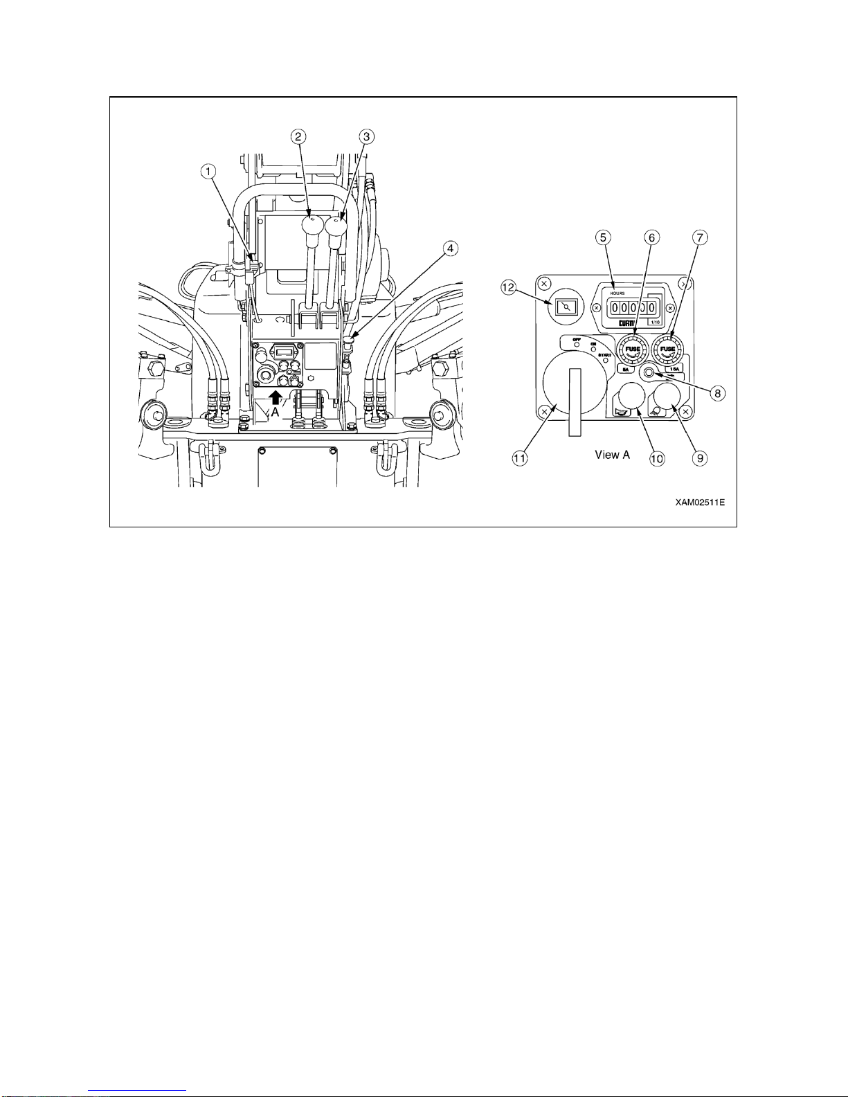
3-3
1.2 NOMENCLATURE OF TRAVEL CONTROL COMPONENTS
① accelerator lever
② L.H. travel lever
③ R.H. travel lever
④ Travel stand lock lever
⑤ Hour meter
⑥ Fuse (5A)
⑦ Fuse (15A)
⑧ Battery charge lamp
⑨ Flood light switch
⑩ Horn switch
⑪ Main starter switch
⑫ Choke Knob
Page 56
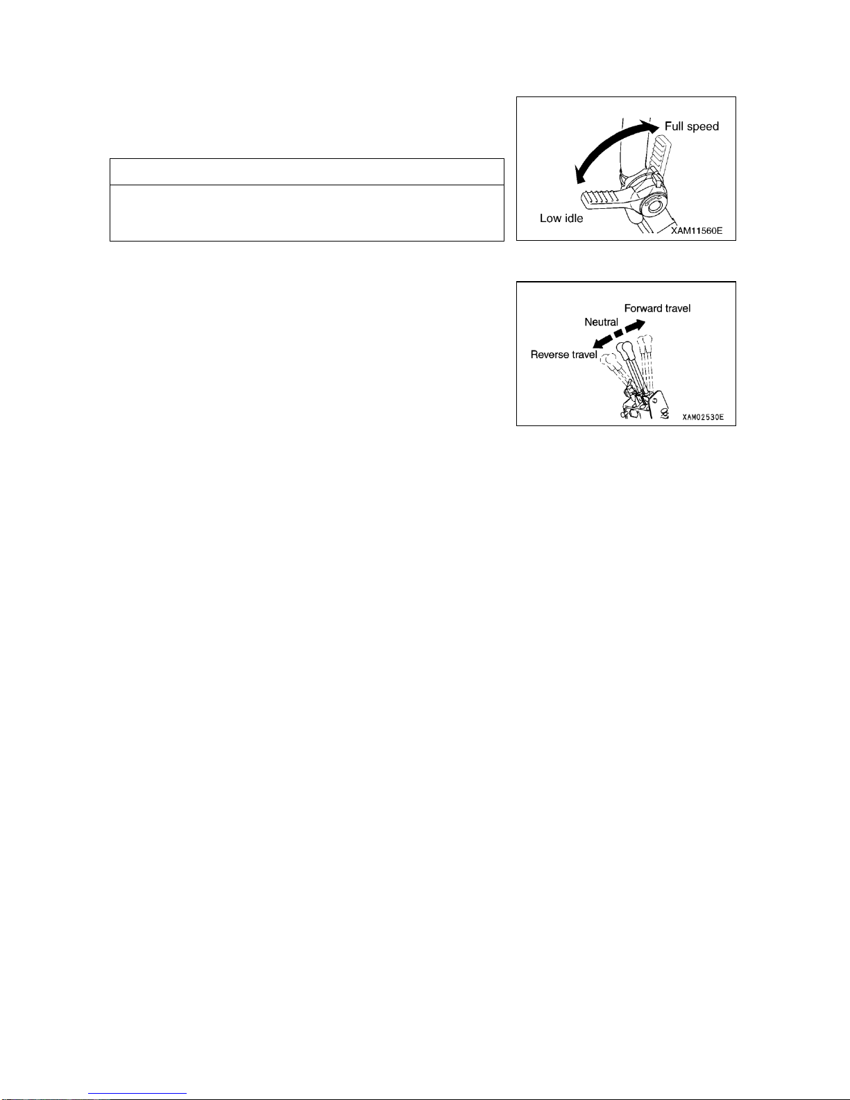
3-4
1.2.1 CONTROL LEVERS
[1] ACCELERATOR LEVER
This lever is to be used for adjusting engine speed or output.
・Low idling: Push the lever forward.
・Full speed: Pull back the lever.
NOTES
・At the desired engine speed for your work, release the lever. It will
stop at that position.
・Accelerator lever is also provided on the crane control panel.
[2] LEFT AND RIGHT TRAVEL LEVERS
Used for traveling forward/backward, stopping, swinging and adjusting
travel speed.
・Forward travel: Push both of the left and right levers forward
simultaneously.
・Neutral: Take your hands off both of the left and right levers
simultaneously.
Levers will return to neutral automatically, causing
the machine to stop.
・Reverse travel: Pull back both of the left and right levers
simultaneously.
・Left turn: Release the left hand side lever.
・Right turn: Release the right hand side lever.
・Spin turn: Move left and right levers respectively in opposite
direction. Left and right tracks will respectively rotate
in opposite direction to make the spin turn.
Page 57
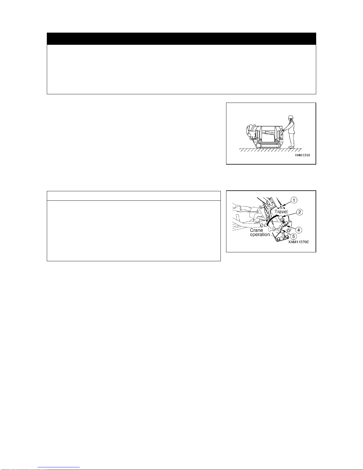
3-5
[3] TRAVEL LEVER STAND
k WARNING
・Before setting the travel lever stand to "Travel Position", be sure to stow the crane and let the machine
assume travel position.
Traveling with the crane not in travel position, may cause it to tip over and serious accident be
incurred.
・When pulling up the travel stand locking lever, be careful not to contact the travel lever, as it may cause
the undercarriage to move.
This stand is to be used for switching between travel control and crane
control.
・For traveling: Pull up the locking lever ② before erecting the entire lever
stand ① forward to the "Travel Position". The machine is in "Travel
Position" when the bottom end of locking lever ② fits into the guide
groove ④.
・For crane operation: Pull up the locking lever ② before pressing the
whole lever stand ① down to the "Crane Work Position". The machine is
in "Crane Work Position" when the end of locking lever ② fits into its
place before the stopper ⑤.
NOTES
・When the travel lever stand is in Travel Position, only the travel
operation is possible.
・Operating the crane or outrigger control lever under such status, will
cause the crane to respond only at very slow speed. Further, under
such status, remote control for crane or outrigger does not actuate the
crane at all.
・For actuating crane or outrigger motion, place the travel stand in
"Crane Work Position".
Page 58
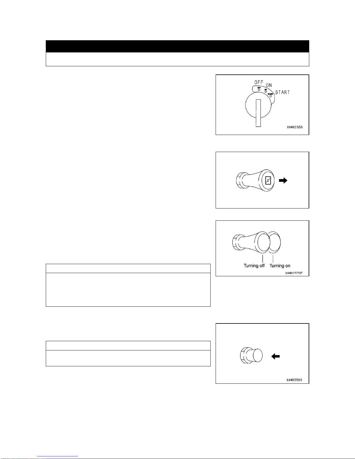
3-6
1.2.2 SWITCHES
[1] MAIN STARTER SWITCH
k CAUTION
When you finish your work, be sure to turn the main starter switch to OFF position.
Used for starting and stopping the engine.
・OFF: At this position, key can be inserted or removed and switches
of all the electric systems go off and engine comes to stop.
・ON: Power flows to all the circuits.
・START: At this position, engine starts. Once the engine starts, take
your hand off the key. The key will automatically return to
ON position.
[2] CHOKE KNOB
This knob is to be used when ambient temperature is low and engine is
difficult to start.
Use the choke in the following manner:
1. Pull the knob all the way back.
2. Place the starter switch at Start position.
3. When the engine starts, press the knob to original position.
[3] FLOOD LIGHT SWITCH
This switch is to be used for turning on the flood light at the machine
front.
・Turning ON: Pull out the switch.
・Turning OFF: Push in the switch.
NOTES
・When the starter switch is at OFF position, the flood light will not go
on even if the switch is pulled out.
・The flood light itself has a switch as well. Normally leave the switch
on the flood light at its ON position.
[4] HORN SWITCH
Used to sound horn.
・To sound the horn: Press the switch.
NOTES
・Horn sound stops as you take your finger off the switch.
・Horn switch is provided on the crane operating side as well.
Page 59
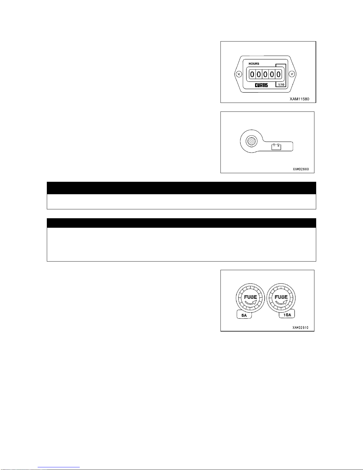
3-7
1.2.3 METER, LAMP AND FUSES
[1] HOUR METER
This meter indicates total working hours of the machine.
When the main starter switch remains at ON position, the meter
progresses even if the machine were in action.
Use this meter as the standard for servicing intervals.
[2] BATTERY CHARGE LAMP
The lamp notifies you of any trouble on charging system.
It goes on when main starter switch is turned to ON position and it is
normal if it goes off as the engine starts and increases speed. Its coming
on during work means a trouble in the charging system.
Stop operation immediately to check.
・Check the alternator belt for proper tension.
[3] FUSE
k CAUTION
For checking or replacing a fuse, make sure that main starter switch is at OFF position.
CAUTION
Fuse protects electric components and wiring from burning.
・Tubular fuse is in use. Be sure to replace it when it is covered with whitish powder due to corrosion.
・When any fuse has blown, be sure to check the relevant circuit and repair it before replacing the fuse.
・Replace any fuse with tubular fuse of the same capacity.
Systems and capacities of fuses are as follows:
・Fuse (5A): For hour meter.
・Fuse (15A): For lamps, horn and crane control systems.
1. Turn the fuse holder on control panel counterclockwise and take it out.
2. Check and replace fuses contained in the removed fuse holder.
3. Install new or checked fuse to the holder and turn it clockwise to
tighten.
Page 60
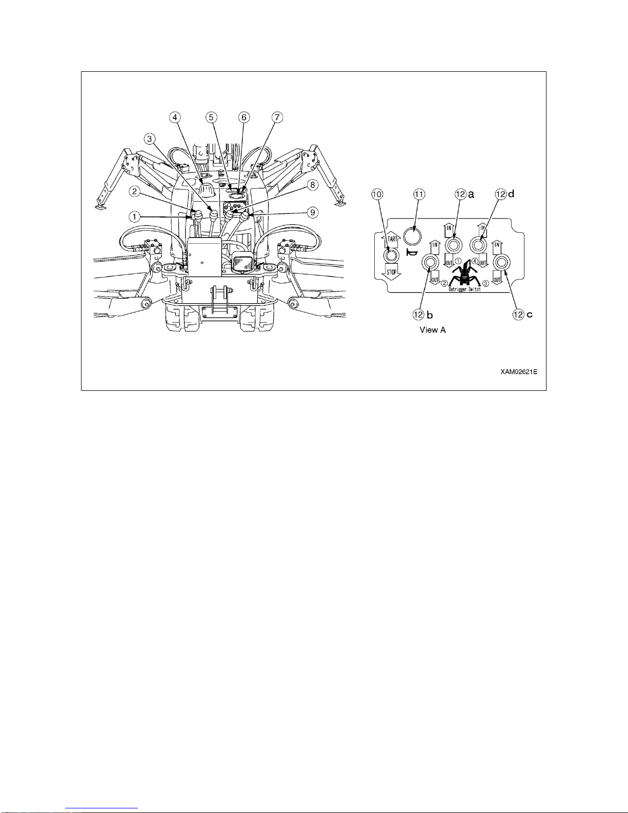
3-8
1.3 NOMENCLATURE OF CRANE CONTROL COMPONENTS
① Accelerator
② Swing lever
③ Boom telescope lever
④ Outrigger mode indicator lamp
⑤ Load meter
⑥ Level instrument
⑦ EMO switch
⑧Winch lever
⑨ Boom derrick lever
⑩ Auxiliary starter switch
⑪ Horn switch
⑫ Outrigger switch
(a) Outrigger ① control switch
(b) Outrigger② control switch
(c) Outrigger③ control switch
(d) Outrigger④ control switch
Page 61
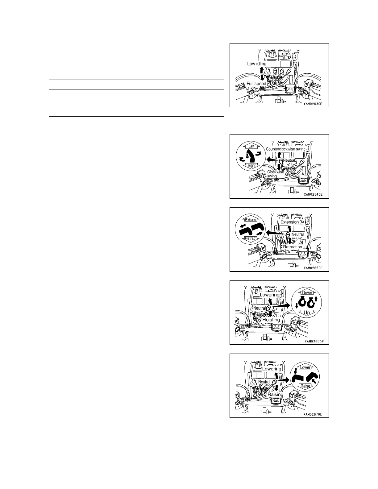
3-9
1.3.1 CONTROL LEVERS
[1] ACCELERATOR LEVER
This lever is to be used for adjustment of engine speed or output.
・Low idling: Push the lever forward.
・Full speed: Pull back the lever.
NOTES
・At the desired engine speed for your work, release the lever. It will
stop at that position.
・Accelerator lever is also provided on the crane control panel.
[2] SWING LEVER
Used for having boom post of the crane swing.
・Counterclockwise swing: Push the lever forward (to Left).
・Neutral: Take your hand off the lever, which will return to Neutral
position, causing the swing to stop.
・Clockwise swing: Pull back the lever (to Right).
[3] BOOM TELESCOPE LEVER
Used for telescoping the boom.
・Extension: Push the lever forward (to Extend).
・Neutral: Take your hand off the lever, which will return to Neutral
position, causing the telescoping of the boom to stop.
・Retraction: Pull back the lever (to Retract).
[4] WINCH LEVER
Used for hoisting the hook of crane.
・Lowering: Push the lever forward (to Down)
・Neutral: Take your hand off the lever, which will return to Neutral
position, causing the brake to be automatically applied and
hoisting and lowering of the hook block to stop.
・Hoisting: Pull back the lever (to Up).
[5] BOOM DERRICK LEVER
Used for derriking the boom.
・Lowering: Push the lever forward (to Lower).
・Neutral: Take your hand off the lever, which will return to Neutral
causing the hoisting of boom to stop.
・Raising: Pull back the lever (to Raise).
Page 62
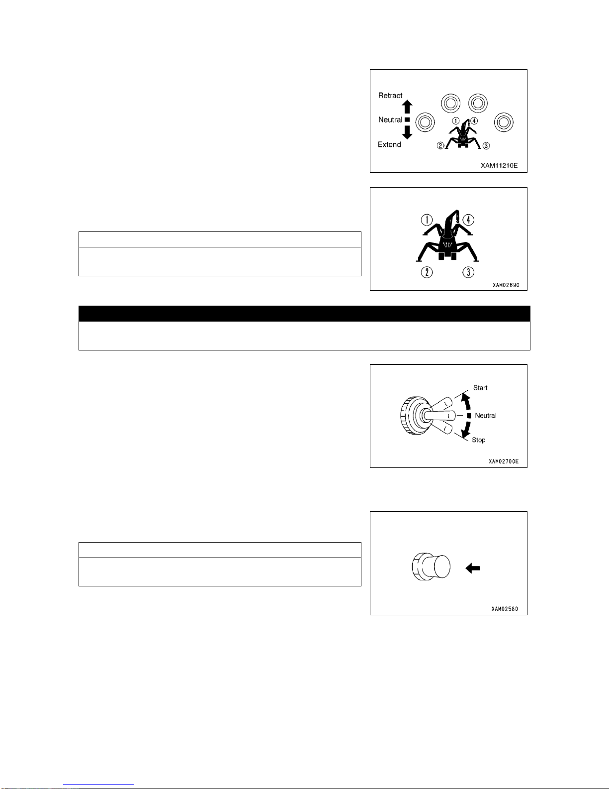
3-10
1.3.2 SWITCHES
[1] OUTRIGGER CONTROL SWITCH
Used for setting and stowing away the outrigger.
This machine has 4 outriggers (① ~④), which can be controlled
individually or simultaneously.
・To retract: Push the switch upward. Outrigger cylinder will be
retracted and the outrigger can be stowed.
・Neutral: Take your finger away from the switch, which will return to
Neutral position and telescoping of the cylinder will
discontinue.
・To extend: Push the switch downward.
Outrigger cylinder will be extended and the outrigger can
be placed.
NOTES
While the outrigger control switch is being operated, outrigger mode
indicator lamp flashes and warning buzzer sounds intermittently.
[2] AUXILIARY STARTER SWITCH
CAUTION
The auxiliary starter switch functions only while main starter switch at travel control is in ON position.
To start-up engine using the auxiliary starter switch, the main starter switch must remain at ON position.
This switch is to be used, to start or stop the engine while crane or
outrigger operation is going on.
・For starting: Push the switch upward and engine will start. Once the
engine is started, release the switch.
・For Neutral: Release the switch and the switch will return to Neutral.
・For stopping: Push the switch downward and the engine will stop.
Do not release the switch until the engine comes to
stop.
[3] HORN SWITCH
Used to sound the horn.
・To sound the horn: Press the switch.
NOTES
・Horn will stop sounding as soon as you release the switch.
・Horn switch is provided at the travel control panel side as well.
Page 63
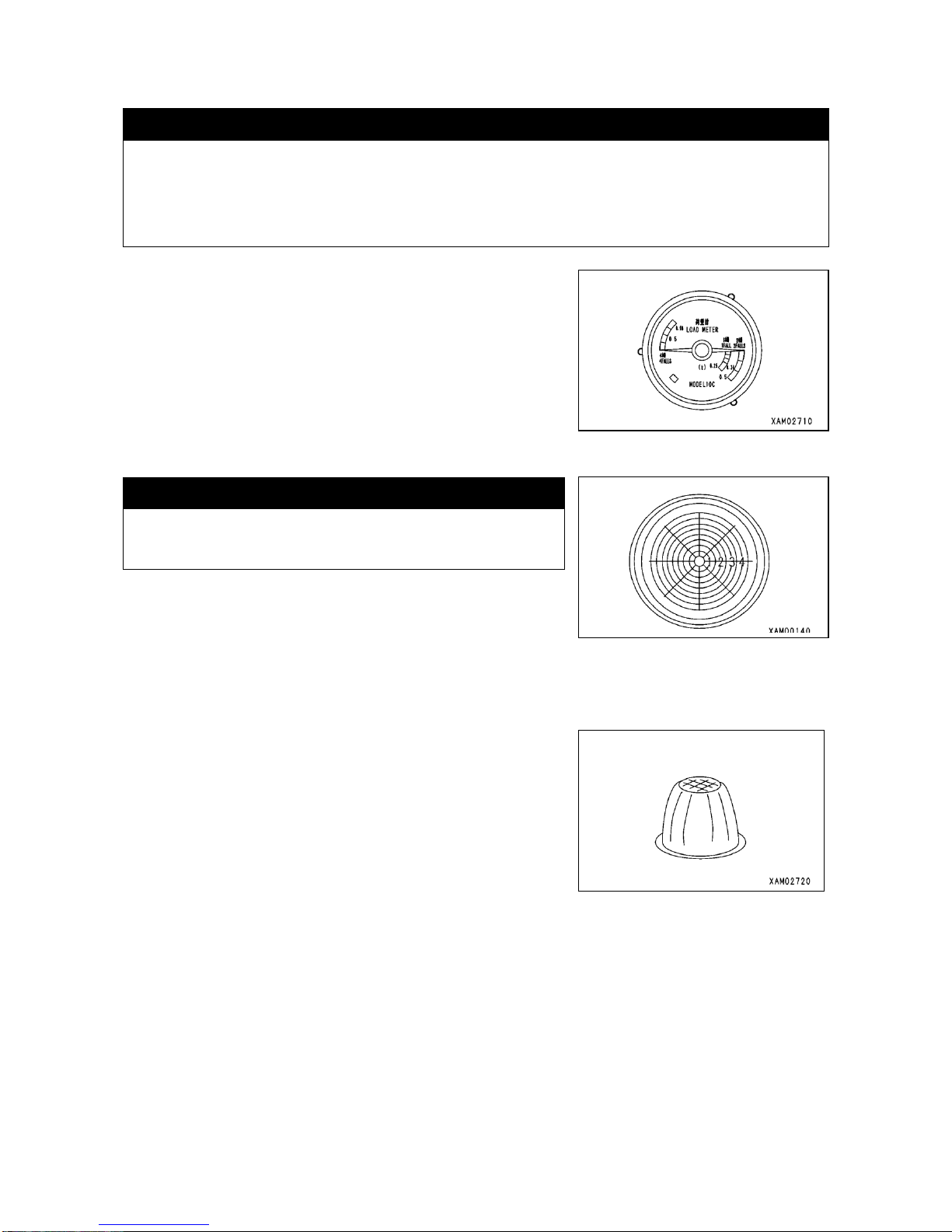
3-11
1.3.3 METERS AND LAMPS
[1] LOAD METER
k WARNING
・Load meter indicates the mass (weight) of load being hoisted with winch. Hoisting any load in excess
of rated load of the crane can cause tipping over or other damage. Crane work should always be
carried out while making sure that the pointer of this meter remains within safety range.
・Failure of the load meter jeopardizes safe crane operation. Load meter should be always kept in
normal conditions with monthly inspection carried out independently.
It indicates the mass (weight) of the load being hoisted with winch.
Scales of the load meter are provided for one, two and four part reeving
according to number of wire rope part reeving of the hook. Read the
scale that corresponds to your number of part reeving.
Standard for this machine is 4 part reeving.
[2] LEVELING INSTRUMENT
k WARNING
For setting up outrigger, adjust the level of machine while
checking it by means of leveling instrument. Performing crane
work with the machine inclined, may result in tipping over.
It indicates inclination of the machine.
Position of bubble tells the inclination of machine and its direction.
Used for checking the levelness of machine when setting up outrigger.
When the bubble comes to the center, the machine is level.
[3] OUTRIGGER MODE INDICATOR LAMP
It notifies that the outrigger is in operation.
Operating the outrigger control switch to Extend or Retract, causes the
lamp to flash and warning buzzer to sound intermittently.
When the Outrigger mode has been selected by means of remote
control, the lamp will flash and warning buzzer sounds intermittently
even if the switch is not operated.
Page 64
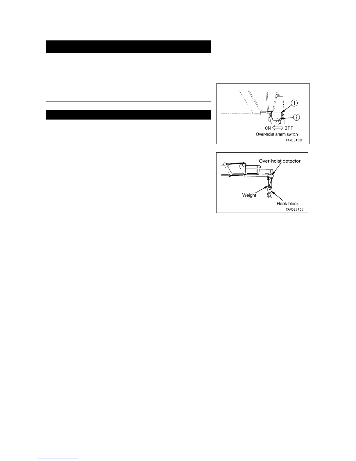
3-12
1.4 OVER-HOIST PREVENTIVE SYSTEM
k WARNING
Before conducting pre-work inspection or starting your crane
work, be sure to turn the switch ② of the over-hoist preventive
system ① to ON position.
If the switch ① remains at OFF position, the alarm system ②
will not actuate, causing not merely the lifted load to hit various
part of the crane causing damage, but the load to fall down and
result in an accident.
CAUTION
Traveling the machine may cause the load to bounce and alarm to
sound. When you let the machine assume travel position, turn OFF
the switch ② for the over-hoist preventive system ①.
The over-hoist preventive system is designed to warn you by sounding
the buzzer when the hook block approaches the boom top end and
pushes up the weight.
When the buzzer sounds, immediately place the winch lever and boom
telescoping lever in Neutral to discontinue the motion, then place the
winch lever in Lowering to cancel the over-hoist status.
Page 65
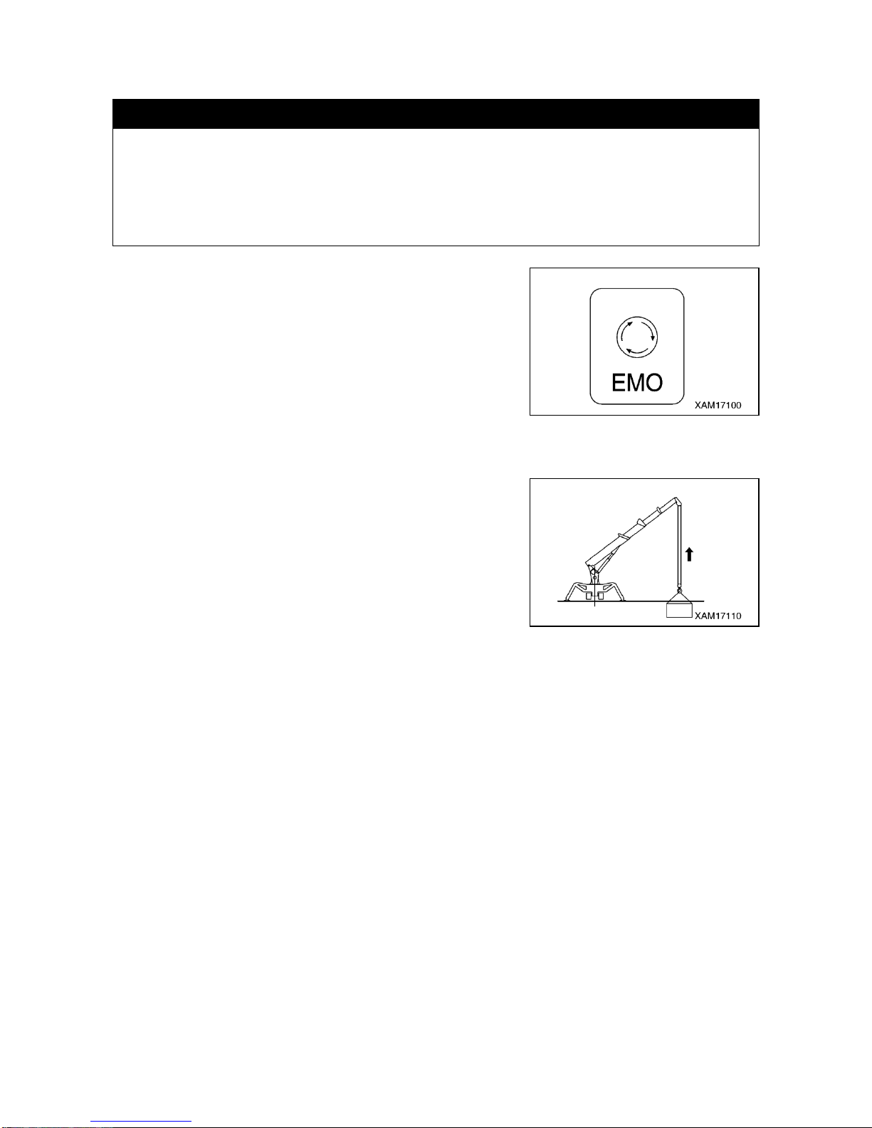
3-13
1.5 EMO SWITCH (EMERGENCY STOP SWITCH)
k WARNING
・EMERGENCY STOP
If any trouble such as an abnormal operation occurs, press the EMO switch at the upper place of the
machinery cover to stop the engine. Then turn the starter switch key to the OFF position to turn off
the electric system, and pull the key out.
・ABNORMAL OPERATION
If you have stopped the engine (machine) besause of an abnormal operation, explain the problem to
your Maeda agent and request repair.
When starting the engine again after stopping it with the EMO switch,
firstly make sure that the cause of the problem has been cleared (the
locking lever of the travel lever stand is at the traveling position.)
Next, reset by turning the switch clockwise.
Make sure that the starter switch is at OFF position, then start the
engine.
1.6 OVER-LOWERING PREVENTION DEVICE
If the wire rope remaining in the winch drum shortens to five turn when
winding down the hook. The limit switch actives, and the hook winding
down operation automatically stops.
Promptly execute the recovery operation when this automatic stop
happened.
Page 66
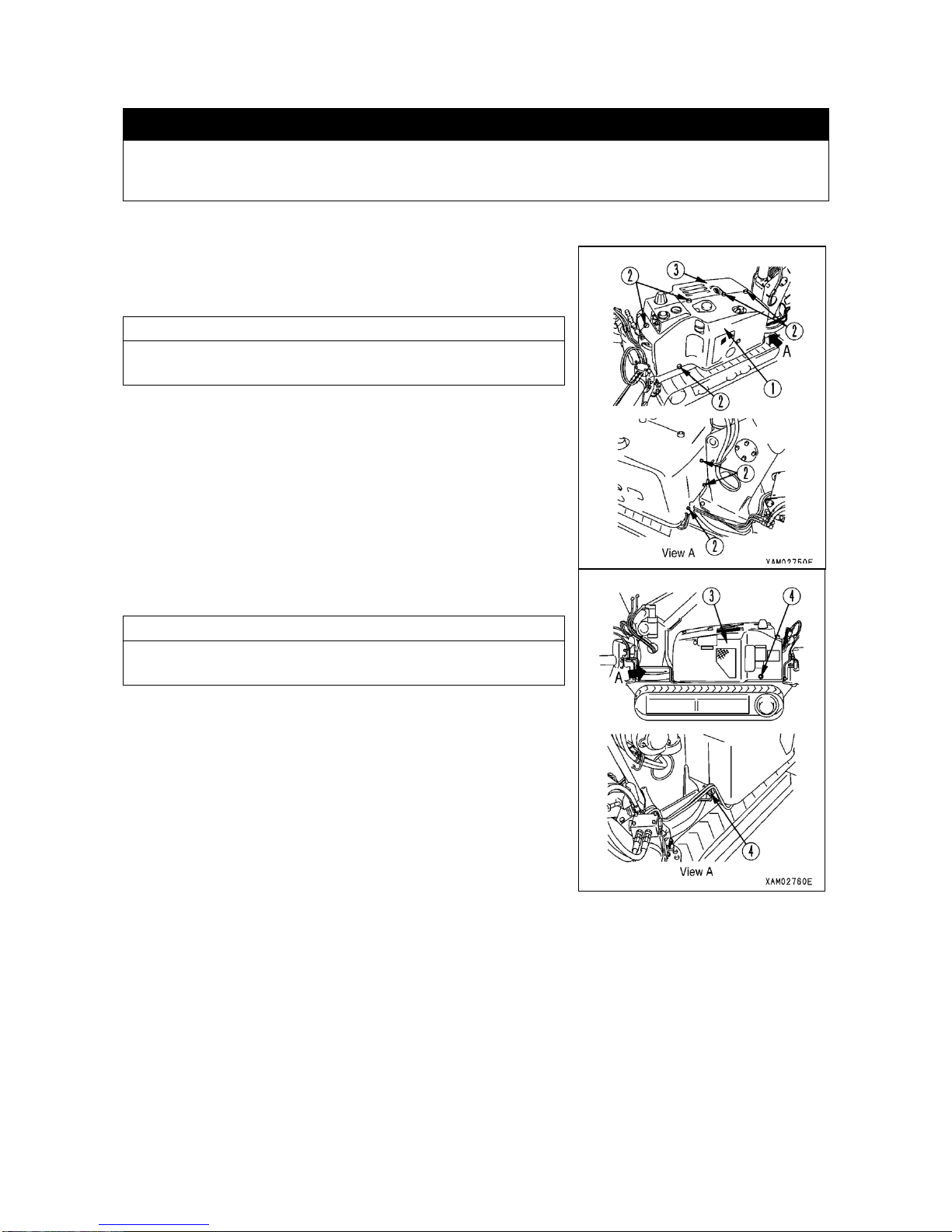
3-14
1.7 MACHINERY COVER
k WARNING
・Before taking off the machinery cover, be sure to shutdown the engine and remove the key.
・Do not remove the machinery cover while engine is still hot such as immediately after completion of
work
[1] REMOVING THE MACHINERY COVER
For servicing the machinery cover internals, remove the machinery
cover in the following manner:
1. Remove 8 mounting bolts ② of left hand side machinery cover ①.
NOTES
The mounting bolts ②are being used in quantity of 4 at the top, 3 at
the rear and 1 on the side.
2. Remove 2 mounting bolts ④ of the right hand side machinery cover
③.
NOTES
The mounting bolts ④ are being used in quantity of one each at the
rear bottom and side bottom.
3. Remove the left side machinery cover ①.
4. Remove the right side machinery cover ③.
[2] REINSTALLATION OF THE MACHINERY COVER
Upon completion of servicing the machinery cover internals, replace the
covers with the removing procedure reversed.
Page 67
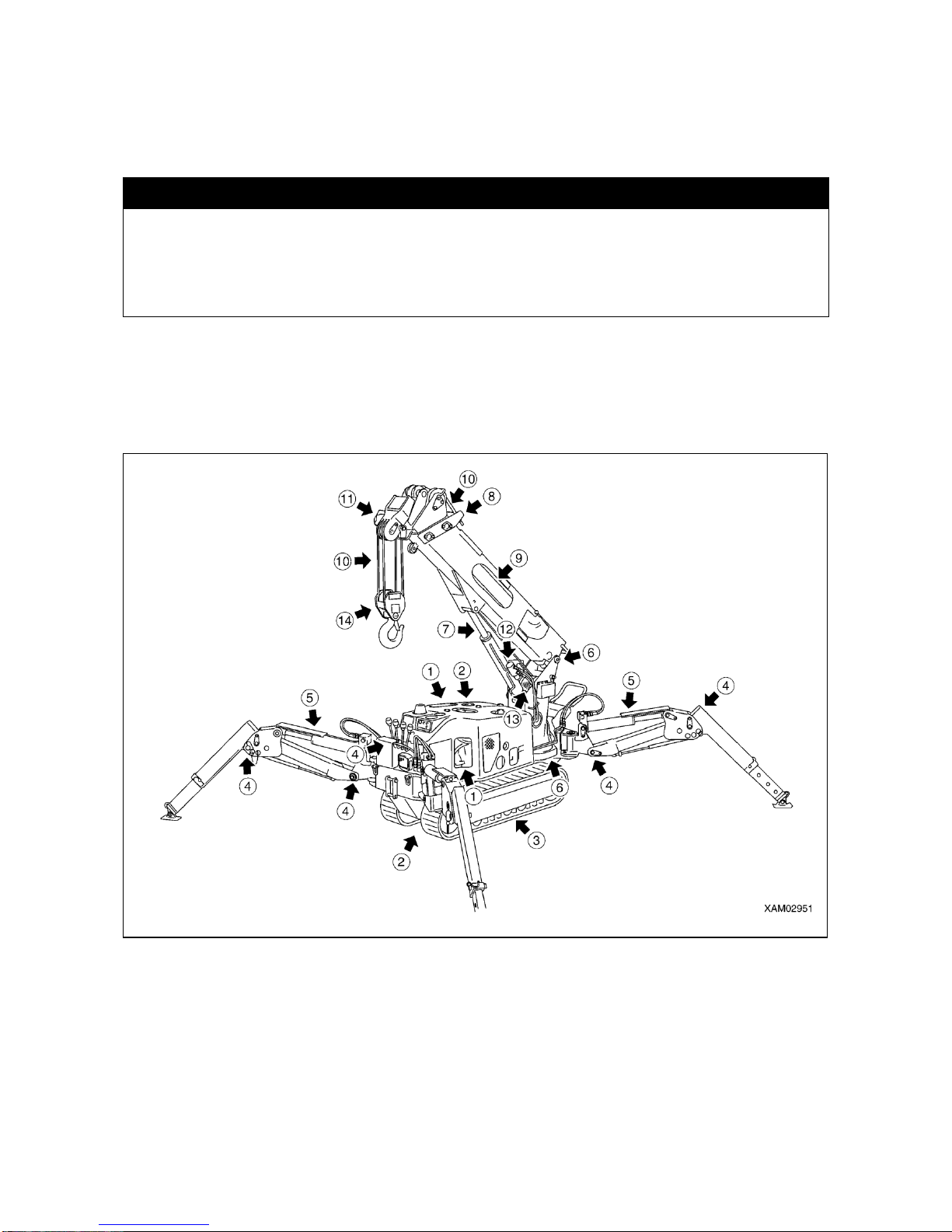
3-15
2.OPERATION CONTROL
2.1 INSPECTION PRIOR TO STARTING UP THE ENGINE
2.1.1 VISUAL CHECK
k WARNING
・This machine has a gasoline engine installed. If you smell gasoline around the engine, it is possible
that it is leaking. Thoroughly check gasoline hose for any crack and its connections for tightness.
・Deposit of inflammable matter or oil leakage around high temperature zone including engine, muffler
or battery may cause fire on the machine. Conduct visual inspection carefully and be sure to repair
any abnormality or contact your dealer.
Before starting up the engine, check around the engine for smell of gasoline.
Inspect externals and bottom of the machine to check for loosened bolt and oil leakage, in addition to checking the
crane and hydraulic systems.
Check for looseness or play in electric wiring and deposit of trash in places where it is exposed to high temperature.
Inspections described in this section should be conducted before the first engine start-up of the day.
① INSPECTION AROUND ENGINE
Check for and remove accumulation or deposit of inflammable items including fallen leaves, wastepaper, trash, oil
or grease on high temperature area such as engine and muffler.
Check for fuel or oil leakage from engine and repair it as necessary.
Check for slackened wiring or loosened connection or trace of burning around starter, alternator or battery and
repair any abnormality that may be found.
② INSPECTION OF HYDRAULIC SYSTEM OF UNDERCARRIAGE
(travel motor, control valve, hydraulic oil tank, hose joint)
Check for loosened pipe connection or oil leakage and repair any abnormality.
Page 68

3-16
③ INSPECTION OF UNDERCARRIAGE (rubber track, track roller, sprocket and idler)
Check for damage, wear, loosened track roller and repair any abnormality. Check for loosened or missing bolt
and retighten as necessary. For details, see “OPERATION, 3. HANDLING OF RUBBER TRACK”.
④ INSPECTION OF OUTRIGGER
Check for crack, bend, damage, wear of support pin or the like and repair as necessary.
⑤ INSPECTION OF OUTRIGGER CYLINDER
Check for loosened pipe connection, oil leakage, wear or damage of support pin or the like and repair it as
necessary.
⑥ INSPECTION OF POST
Check for crack, bend, damage in various area, loosened post and slew ring mounting bolts, loosened swing
system speed reducer mounting bolt, loosened pipe connections or oil leakage thereof or the like and repair any
abnormality detected.
⑦ INSPECTION OF DERRICK CYLINDER
Check for loosened pipe connection, oil leakage, wear or damage of support pin or the like and repair it as
necessary.
⑧ INSPECTION OF BOOM
Check for crack, bend, damage in various area, wear of support pin or the like and repair it as necessary.
Check for loosened mounting bolt of the support pin lock plate portion and tighten it as necessary.
⑨ INSPECTION OF TELESCOPE CYLINDER
Check for loosened pipe connection or oil leakage and repair it as necessary.
⑩ INSPECTION OF WIRE ROPE
Check for damage, deformation, wear, twist, kink and corrosion and replace where necessary. For details, see
“OPERATION, 4. HANDLING of WIRE ROPE”.
⑪ INSPECTION OF OVER-HOIST PREVENTIVE DEVICE
Check the wire rope of over-hoist weight for damage or the like and replace it as necessary.
⑫ INSPECTION OF WINCH MOTOR
Check for loosened pipe connection, oil leakage or loosened mounting or the like and repair it as necessary.
⑬ INSPECTION OF WINCH DRUM
Check the drum for crack, bend, damage or the like and repair it as necessary. Check hoisting wire rope for
disorderly take-up and repair it as necessary
⑭ INSPECTION OF HOOK BLOCK
Check hook and sheaves for crack, bend, damage or the like and repair where necessary. Check hook and
sheaves for proper rotation and repair it as necessary.
Page 69
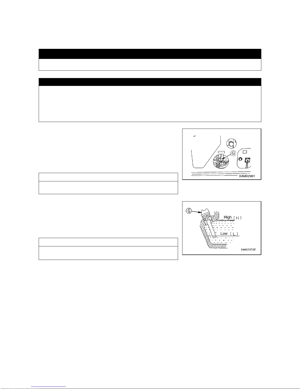
3-17
2.1.2 INSPECTION BEFORE STARTING YOUR WORK
Inspections described in this section should be conducted before the first engine start-up of the day.
[1] ENGINE OIL LEVEL CHECK AND REPLENISHMENT
k WARNING
After oil level check and replenishment, install oil level gauge properly to prevent the gauge from falling
off during operation, which may cause scalding due to shooting hot oil.
CAUTION
・As for the oil to be used, see “INSPECTION AND MAINTENANCE, 5.1 APPLICATION OF LUBRICANT BY
AMBIENT TEMPERATURE”. Use of oil which is not recommended, may shorten the service life of your
engine. Be sure to replenish with recommended oil.
・Level of engine oil should be maintained properly. Excessive feed of oil may lead to its increased consumption
or its pre-matured deterioration as its temperature is prone to rise. Insufficient oil on the other hand may cause
seizure in engine.
1. Park the machine on level ground.
2. Turn and take out the oil level gauge G and wipe it clean with waste
cloth.
3. Insert the oil level gauge G into filler port and pull it out.
NOTES
Do not turn-in the gauge G.
4. If oil level remains between H and L marks on the rod, the level is
proper.
5. If the level does not reach L mark, replenish with oil through filler port.
NOTES
Fill engine oil right up to the opening of the filler port.
6. After replenishment, tighten the oil level gauge G securely.
Page 70
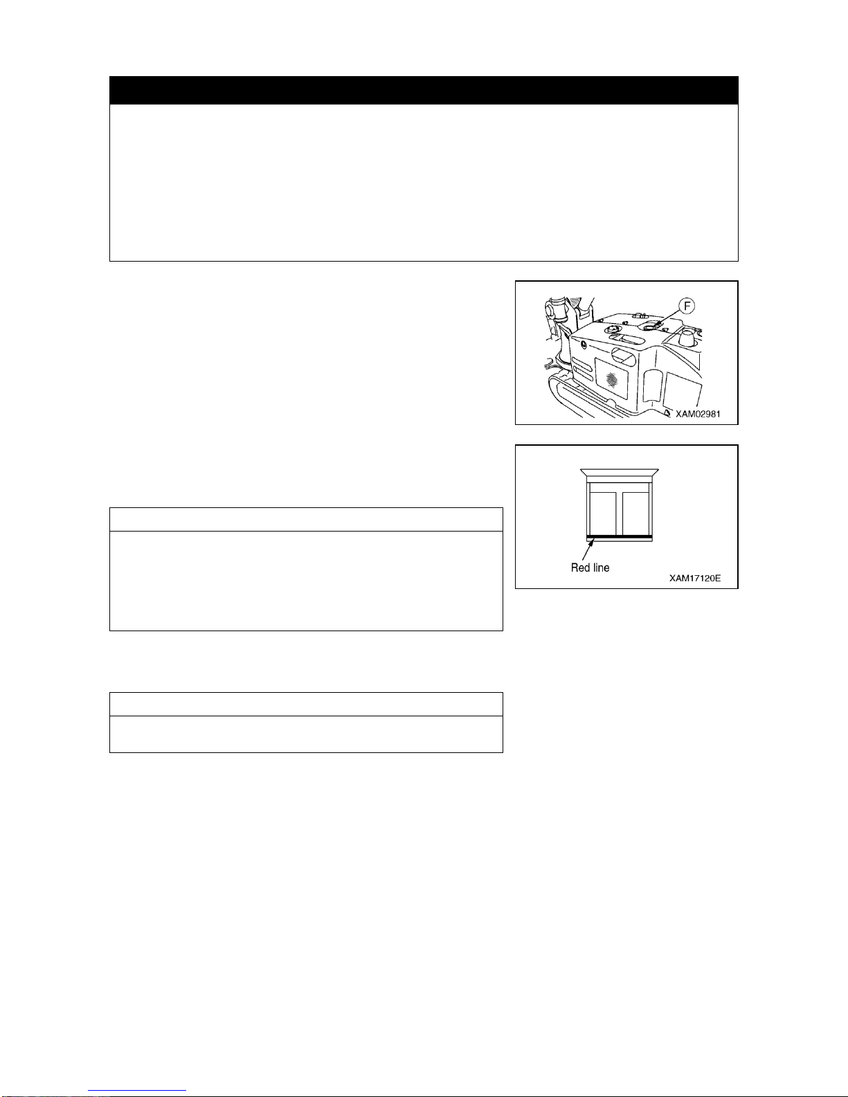
3-18
[2] FUEL LEVEL CHECK AND REPLENISHMENT
k DANGER
・Fuel in use is gasoline (Octane number: 89~92).
・Be careful about fire including that of lit cigarette.
・For replenishment of fuel, be sure to shutdown the engine. Feeding fuel with engine running, may
cause inflammation due to spilled fuel on heated muffler.
・Excessive feed of fuel is dangerous as it may cause spilling. Stay on the slightly lower side of
specified maximum level. Any spilled fuel should be wiped off thoroughly.
・After replenishment, close the tank cap securely.
・Fuel must not be above the red line of the bottom of the fuel filter. Fuel may leak when traveling on
slopes if above the red line.
1. Removing the cap F, check the fuel filter being positioned inside the
fuel tank to see if the fuel level is in the neighborhood of the red line on
the bottom section of the fuel filter.
2. If fuel is insufficient, supply the fuel up to the red line on the bottom
section of the fuel filter.
NOTES
Do not use the fuel level gauge being positioned on the upper surface
of the fuel tank.
If you supply the fuel watching this fuel level gauge, you may
oversupply the fuel.
Therefore, be sure to watch the red line on the bottom section of the
fuel filter when supplying the fuel.
3. After replenishment, turn the tank cap F to close it securely.
NOTES
After a day's work, be sure to fill the tank with fuel.
Page 71
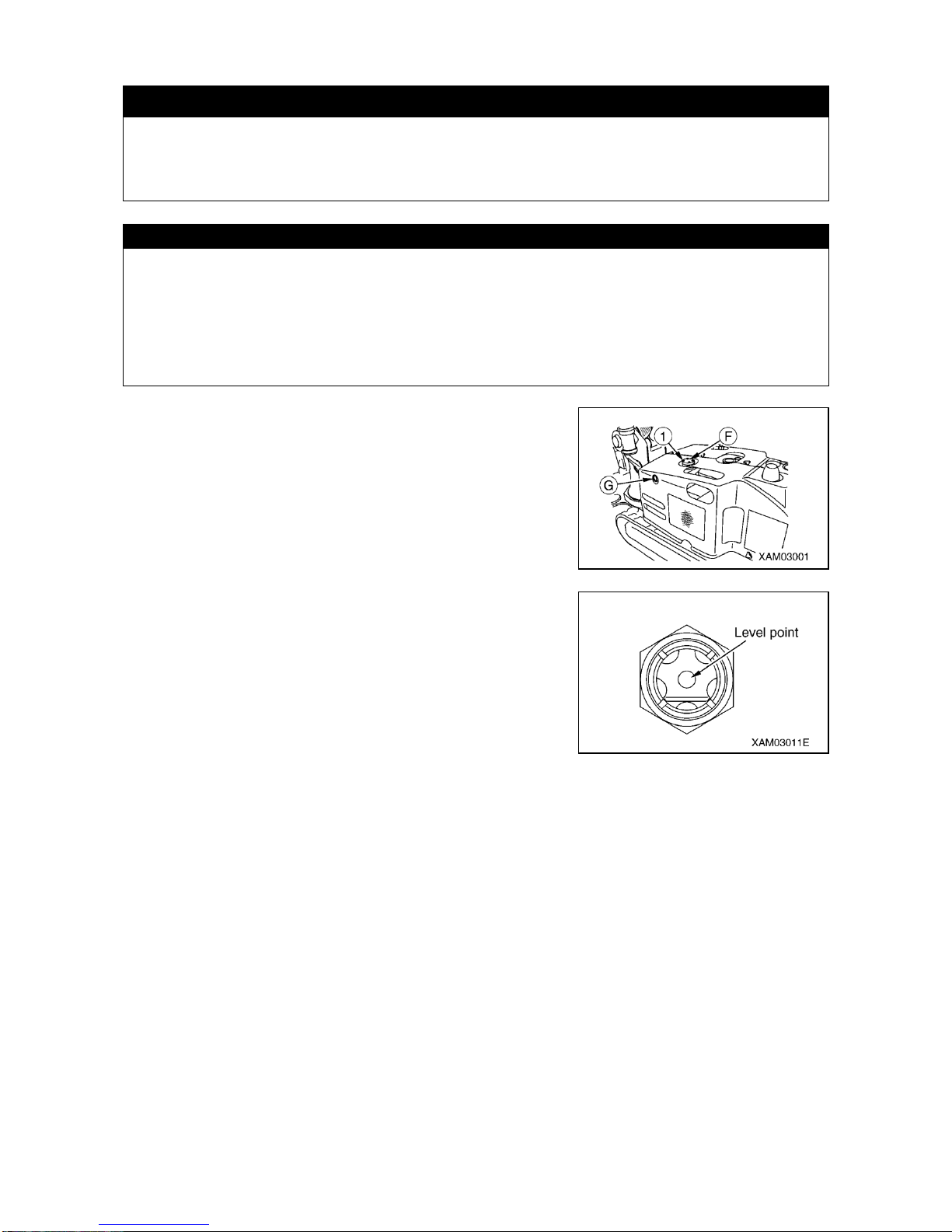
3-19
[3] HYDRAULIC OIL TANK LEVEL CHECK AND REPLENISHMENT
k WARNING
・Removing the hydraulic oil tank cap may cause oil to gush out.
Turn the cap slowly and let internal pressure escape before removing it.
・After replenishment, close the tank cap securely. The cap may drop off during operation otherwise,
causing serious scalding with hot oil gushing out.
CAUTION
・For the type of oil to use, see “INSPECTION AND MAINTENANCE, 5.1 APPLICATION OF LUBRICANTS BY
AMBIENT TEMPERATURE”.
・Before checking the oil level, let the machine assume travel position. Checking the oil level with the machine
remaining in working position tends to cause over-filling, because oil in each cylinder may not have returned to
the tank.
・Do not feed oil to exceed the level point on the gauge (red dot).
Excessive filling may cause oil to gush out through air breather H while traveling or during crane work.
1. Check the oil level gauge G on the left side of machinery cover to
see that oil is up to the level point (red dot).
2. If insufficient, remove 4 mounting bolts ① and remove the tank cap
F at the hydraulic tank top, replenish with hydraulic oil through filler
port while watching the level gauge G.
3. Upon replenishment, tighten the tank cap F securely.
Page 72
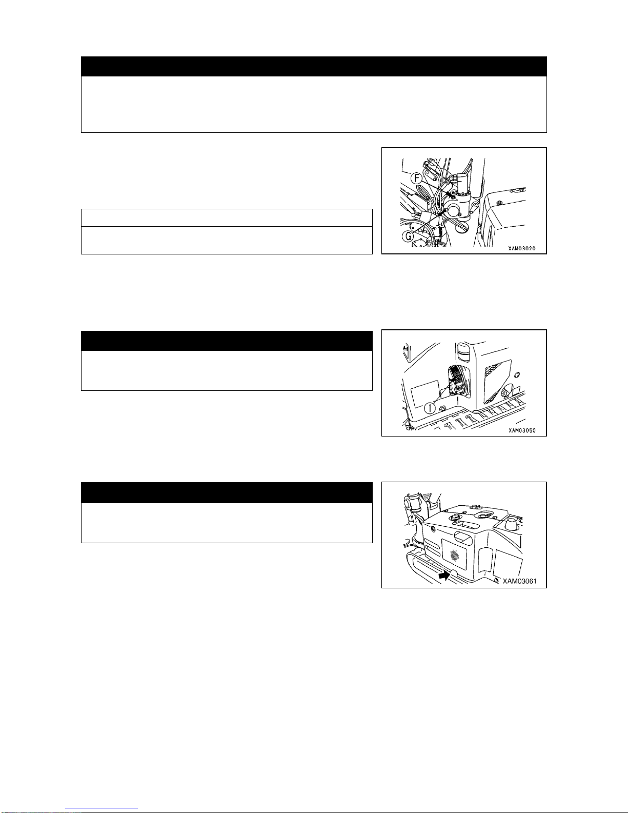
3-20
[4] WINCH SPEED REDUCER CASE OIL LEVEL CHECK AND REPLESHMENT
CAUTION
・For the type of oil to use, see “INSPECTION AND MAINTENANCE, 5.1 APPLICATION OF LUBRICANTS BY
AMBIENT TEMPERATURE”.
・After checking the level of and replenishing with oil, use seal tape or the like at thread portion of level check plug
and filler plug to prevent leakage before tightening them securely.
1. Remove oil level check plug G from the winch reducer case and see
that oil flows out of the plug hole.
2. If insufficient, with the filler plug F at the winch reducer case top
removed, feed gear oil through the plug hole.
NOTES
Feed oil until oil flows out of the oil level check plug.
3. After replenishment, tighten the oil level check plug G and filler hole
plug F securely.
[5] CHECKING AND CLEANING THE RECOIL STARTER
CAUTION
Clogging of the recoil starter screen may cause engine to over-heat,
shortening its useful life. Make sure to check the recoil starter screen
and clean it as necessary.
Check the recoil starter screen ① through inspection panel in machinery
cover to make sure that there is no deposit of dust of paper or straw or
dead leaves and remove them, if any.
[6] INSPECTING AND CLEANING THE ENGINE EXHAUST HOLE
k WARNING
Deposit of dust of paper or straw or dead leaves at engine
exhaust hole may constitute cause of fire. Be sure to check and
keep the hole clean.
Check the engine exhaust hole for deposit of dust, paper, straw or dead
leaves and remove them, if any.
Page 73
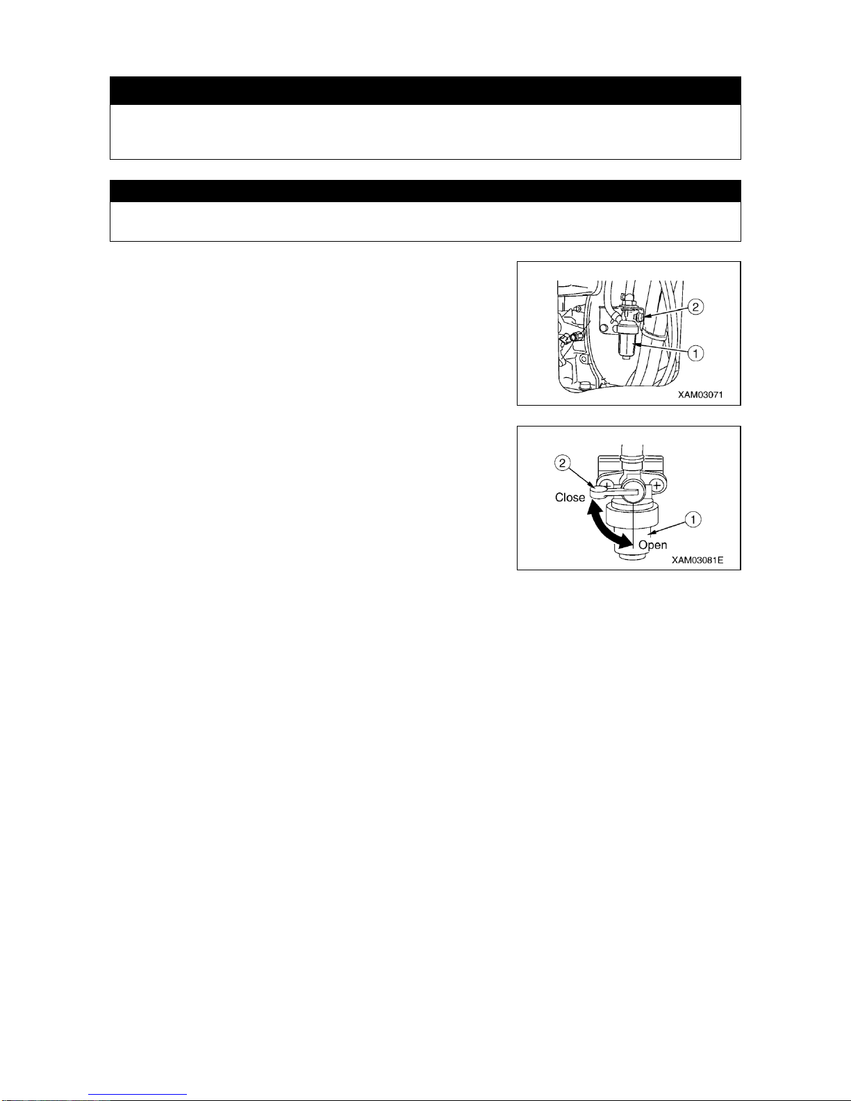
3-21
[7] INSPECTION AND CLEANING OF FUEL FILTER POT
k WARNING
・Filter pot contains gasoline. When you clean it, be careful about fire including lit cigarette.
・If fuel is spilled, be sure to wipe it off.
CAUTION
Water or trash remaining in the filter pot constitutes a cause for engine trouble. Check the filter pot internals and
remove them.
1. Remove the machinery cover. For details, see “OPERATION, 1.7
MACHINERY COVER”.
2. Check the filter pot ① at the bottom of air cleaner to make sure that
there is no water or dust remaining in it and the screen is not clogged
with dust.
3. If any water or dust is found to remain inside the filter pot, clean the pot
internals in the following manner:
(1) Turn the fuel lever ② to horizontal position (Close) to stop fuel
flow.
(2) Turn the filter pot ① and remove the filter pot ① and screen.
(3) After cleaning the filter pot ① and screen with kerosene, replace
them to their original position.
(4) After reinstallation of the filter pot ① and screen, turn the fuel lever
② to vertical position (Open).
4.After checking and cleaning the filter pot, replace the machinery cover.
For details, see “OPERATION, 1.7 MACHINERY COVER”.
Page 74
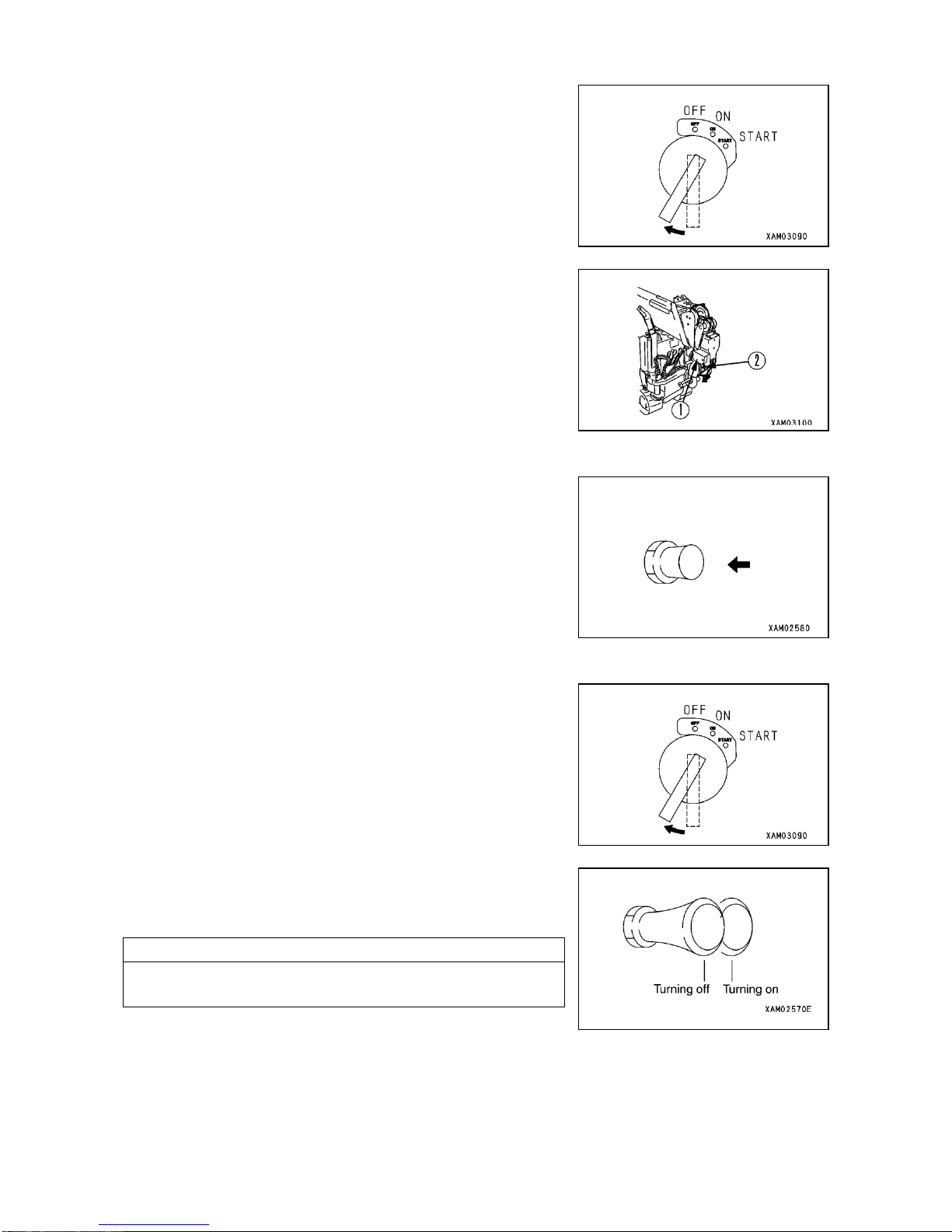
3-22
[8] INSPECTION OF HORN AND OVER-HOIST PREVENTIVE DEVICE
1. Insert key to main starter switch and turn it to ON position to
conduct following check:
2. Make sure that warning buzzer sounds at over-hoist preventive
system ①.
Push down the lever ② of over-hoist preventive system ① and
make sure that the buzzer stops sounding.
If the warning buzzer does not sound from the beginning, run-down
dry battery or defect in the system or wiring failure is conceivable.
If the buzzer does not stop sounding, trouble in the system is
conceivable. Contact your dealer or service shop for repair.
3. Press the horn switch and make sure that horn sounds. If not,
trouble in the horn or a wiring failure is conceivable. Contact your
dealer for repair.
[9] INSPECTION OF FLOOD LIGHT
1. Insert key to main starter switch and turn it to ON position.
2. Pull the flood light switch to see if the flood light at machine front goes
on. If it does not, blown bulb or wiring failure is conceivable. Contact
your dealer for service.
NOTES
Switch is provided on the flood light itself as well. This switch also
should be turned ON.
Page 75
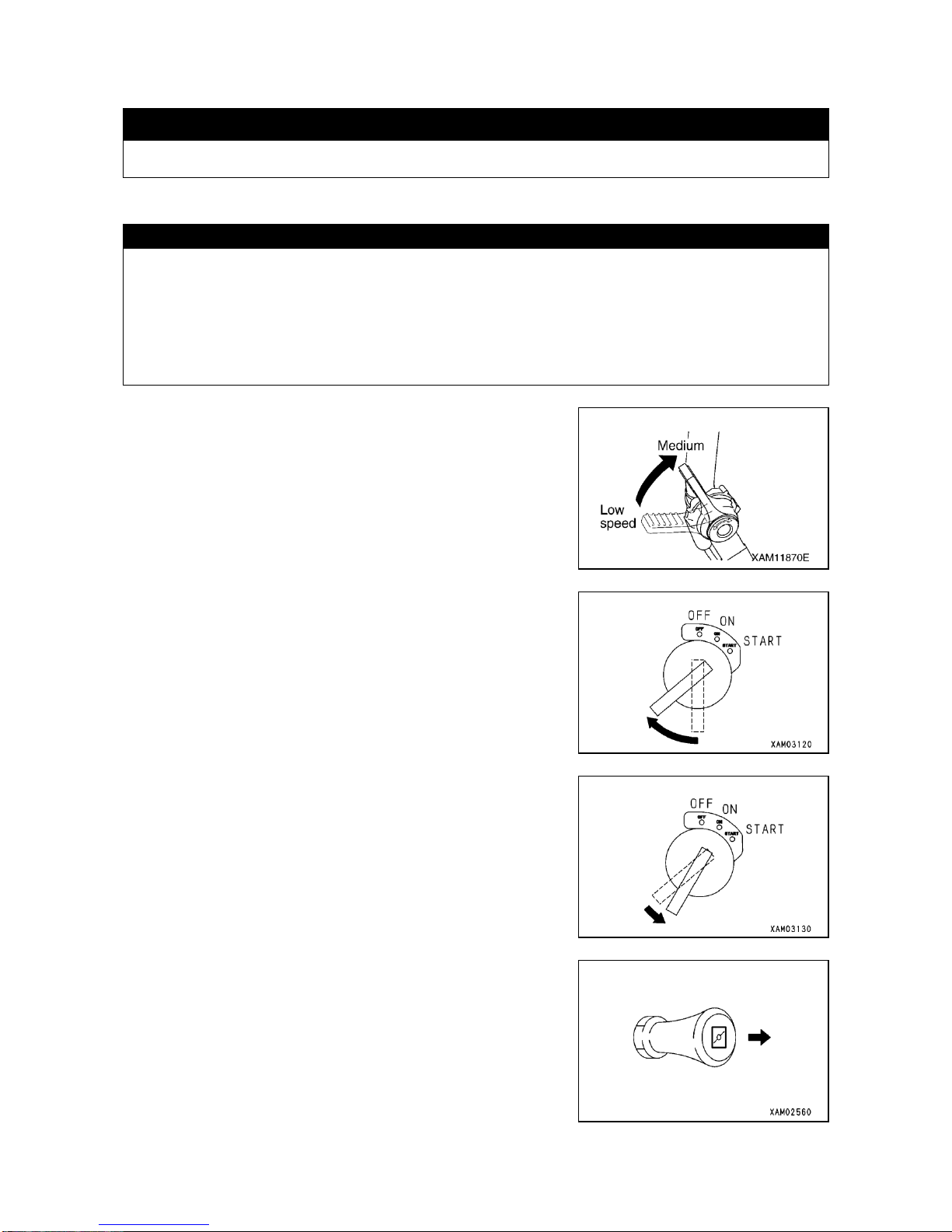
3-23
2.2 STARTING UP THE ENGINE
k WARNING
Before starting up your engine, make sure that there in no person or obstacle around and sound horn.
2.2.1 STARTING UP THE ENGINE WITH MAIN STARTER SWITCH
CAUTION
・Do not keep the starter turning for more than 5 seconds. It accelerates discharge of battery. If the engine fails to
start, wait for about 2 minutes before attempting again.
・When ambient temperature is low or engine does not start easily, pull the choking knob and proceed with
starting procedure.
・Before starting up the engine, make sure that fuel lever of fuel filter pot is in vertical (Open) position.
・Make sure that main switch on remote control box is in OFF position.
1. Pull back the accelerating lever and place it at medium engine speed
zone (about midway).
2. Insert the key into main starter switch and turn it to Start position.
3. When the engine starts, release the key, It will return to ON position
automatically.
4. If the engine is difficult to start, pull back the choke knob before trying
again. If the engine starts, return the choke knob to original position.
Page 76
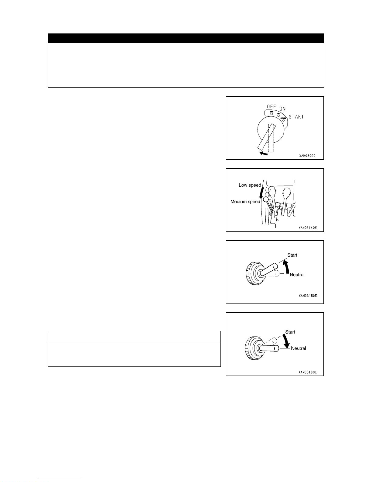
3-24
2.2.2 STARTING THE ENGINE WITH AUXILIARY STARTER SWITCH
CAUTION
・For starting the engine with auxiliary starter switch in use, have the main starter switch placed in ON position.
・Do not continue to turn the starter for more than 5 seconds. It will accelerate the discharging of the battery. If the
engine fails to start, wait for about 2 minutes before giving it a try again.
・Before starting the engine, make sure that the fuel lever of fuel filter pot is in vertical position (Open).
・Make sure that main switch in remote control system box is at OFF position.
1. Insert key into main starter switch and turn it to ON position.
2. Pull back the accelerator lever at crane control system to the medium
engine speed zone (about midway).
3. Push the auxiliary starter switch upward.
4. If the engine starts, release the auxiliary starter switch and the switch
will return to Neutral position automatically.
NOTES
If your engine is difficult to start, see “OPERATION 2.2.1 STARTING
THE ENGINE WITH MAIN STARTER SWITCH” and use the main
switch to start it.
Page 77
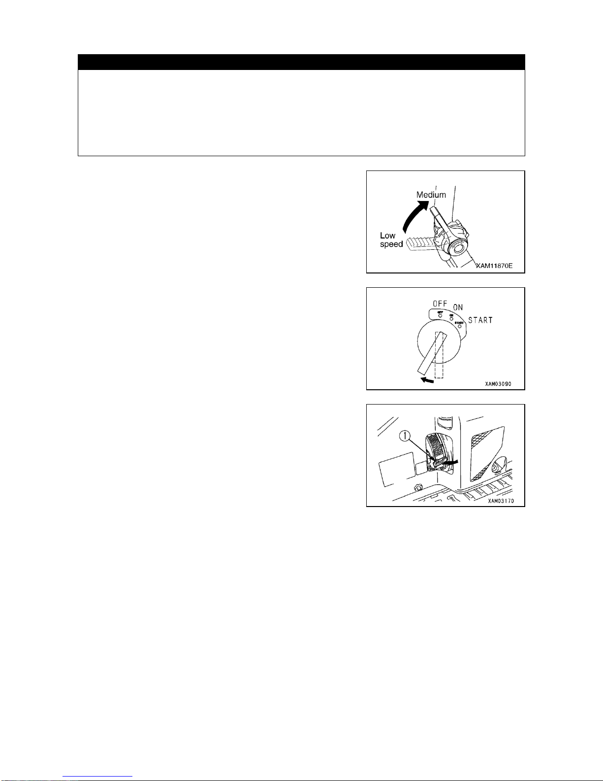
3-25
2.2.3 STARTING THE ENGINE WITH RECOIL STARTER IN USE
CAUTION
・Recoil starter is for emergency use such as in case of electric system deficiency including starter failure, battery
rundown due to discharging or the like. Do not use this starter unless defect is found in connection with electric
system.
・When you start engine by means of recoil starter, main starter switch should be in ON position.
・If ambient temperature is low and starting is difficult, pull the recoil starter knob strongly and quickly.
・Before starting the engine, make sure that fuel lever of fuel filter pot is in vertical (Open) position.
・Make sure that the main switch at remote control box is at OFF position.
1. Pull back the accelerator lever to place the engine at medium speed
position (midway).
2. Insert key to main starter switch and turn it to ON position.
3. Pull back the recoil starter knob ① slowly and make sure of the point
where resistance grows greater (where starter pawl meshes) and
from that point, pull the knob ① quickly,
4. When the engine having started, return the recoil starter knob ①
slowly back to its original position.
Page 78
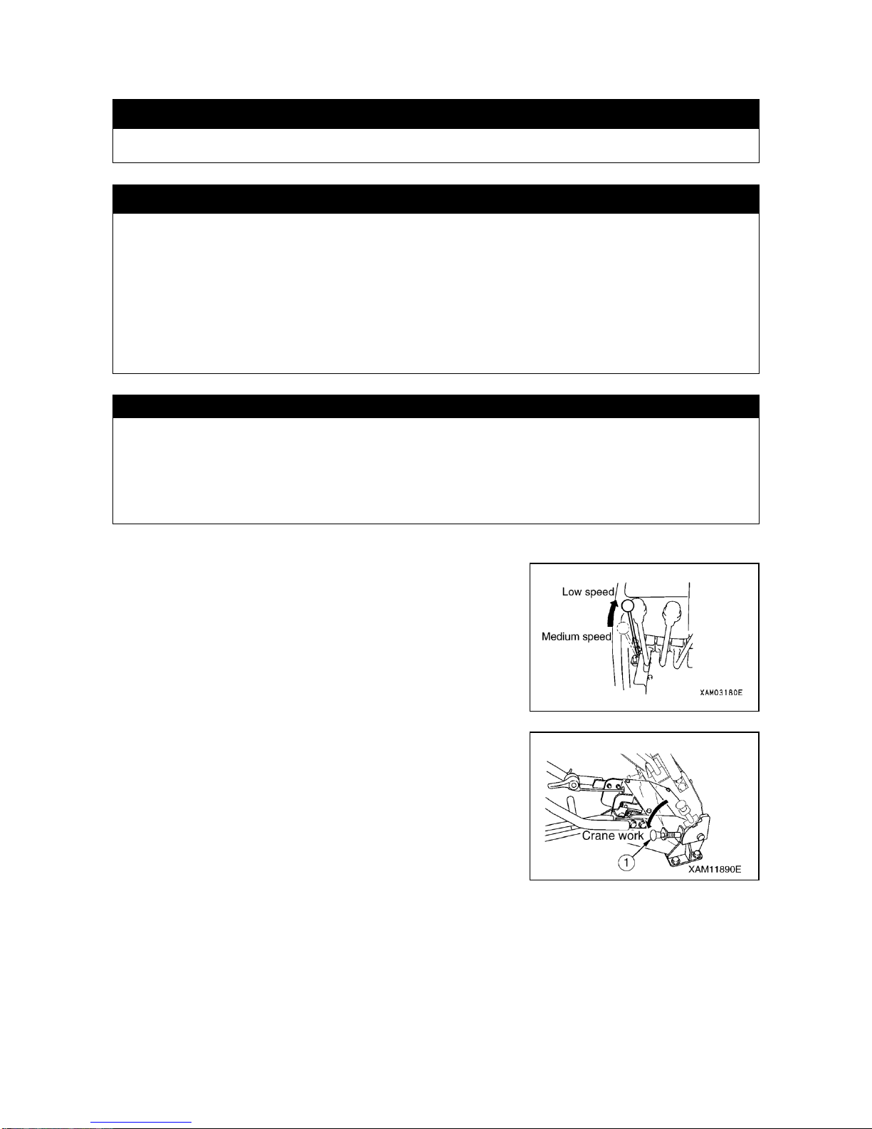
3-26
2.3 OPERATION AND CHECKING AFTER ENGINE HAS STARTED
k DANGER
While engine is running, never replenish with fuel (gasoline). Gasoline is a very inflammable type of
fuel. Be sure to stop the engine for refueling.
k WARNING
・If any trouble develops during warm-up run, promptly turn the main starter switch to OFF position for
an emergency stop. Engine will stop and power for electric system will go off.
・Make sure to conduct warm-up run. Particularly in cold climate, sufficient warm-up run is essential.
Without it, reaction to control lever by travel or crane system will be slow, leading to serious accident.
・After warm-up run, be sure to check actuation of crane function. While doing so, use care to avoid
interference or collision between hook block and boom.
・If any abnormality should be detected during these functional check, promptly make the emergence
stop for required repair. Operating the crane with abnormality remaining may lead to serious
accident.
CAUTION
・It is appropriate that hydraulic oil is used in the temperature range of 50 to 80oC. Even when you have to work
in low temperature, at least the oil temperature should be raised to 20oC before starting your work.
・Do not race the engine in haste until warm-up run is completed.
・After engine has started, check that battery charge lamp has gone off. If not, repair the situation.
・Running engine for long time at low speed may cause trouble due to lack of lubrication at cylinder head.When
you use engine at low speed, race the engine once a day for about 5 minutes.
Once the engine starts, perform warm-up run in the following manner:
1. Push the accelerator lever forward (all the way to the stroke end) to
place the engine at low speed and run it at idling speed for about 5
minutes.
2. Check for abnormal exhaust color, sound or vibration of the engine
and repair it as necessary.
3. Pull back down the travel lever stand so that locking lever ① is in
Crane Work position.
4. Set up the outrigger. For details, see “OPERATION, 2.12 SETTING
UP THE OUTRIGGER”.
5. Loosen the wire rope which has been locking the hook block, before
disengaging the hook block from its hanger. For details, see
“OPERATION, 2.14 BEFORE CRANE WORK”.
Page 79
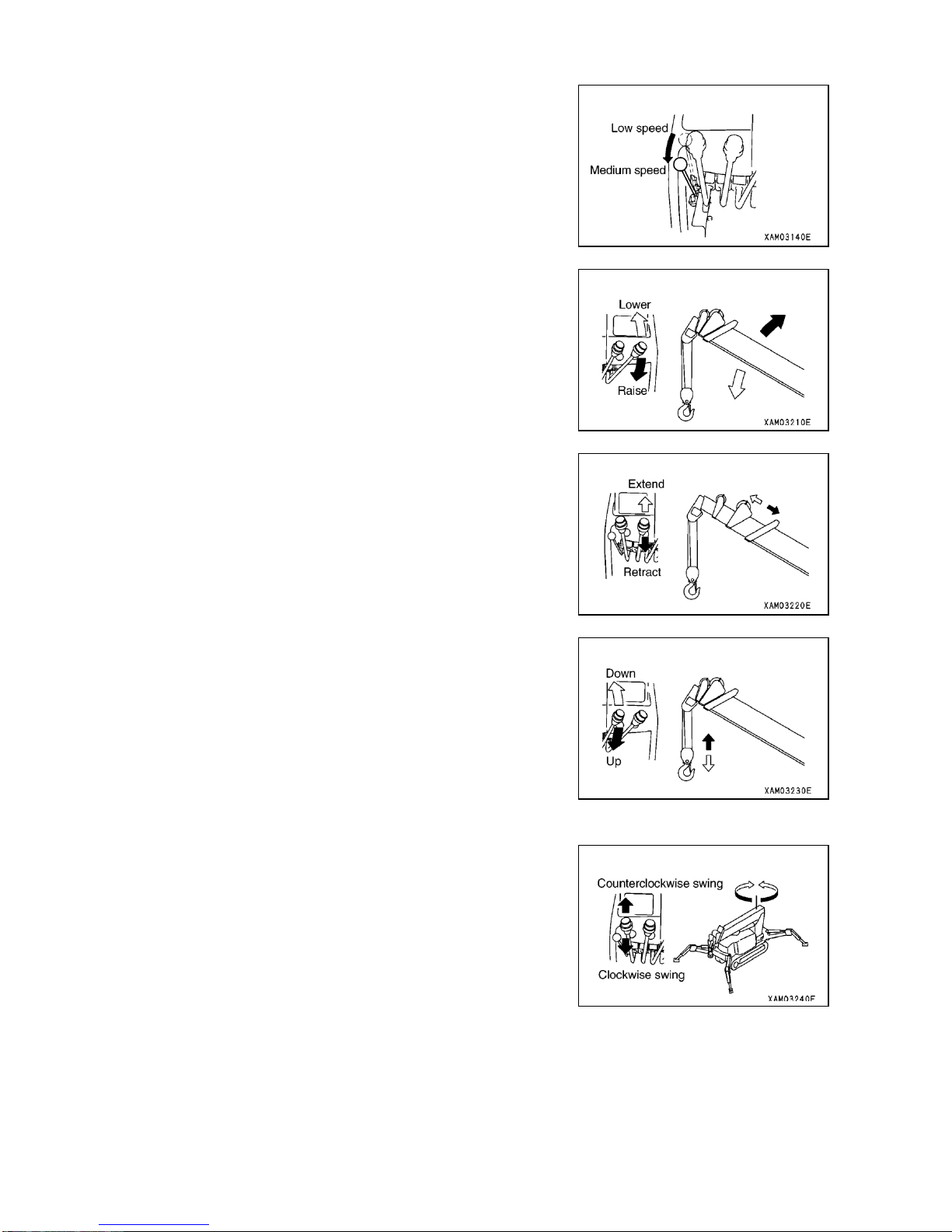
3-27
6. Pull back the accelerator lever on the crane control side to place the
engine at medium speed (midway).
7. Slowly operate the boom derrick lever back and forth so that derrick
cylinder extends and retracts to its stroke end to check that its function
is normal. If not, repair it as necessary.
8. Slowly operate boom telescoping cylinder back and forth so that the
boom extends or retracts to its stroke end to check that its function is
normal. If not, repair it as necessary.
9. Slowly operate winch lever back and forth to check that hook block is
hoisted and lowered smoothly, that it stops immediately when the
winch lever is returned to Neutral position and that the winch does not
take up the rope in disorderly manner. Repair any abnormality as
necessary.
10. Slowly operate swing lever back and forth to check that the crane
swings clockwise and counterclockwise smoothly more than 360
degrees respectively and that it stops immediately when the swing
lever is returned to Neutral. Repair any abnormality as necessary.
Page 80
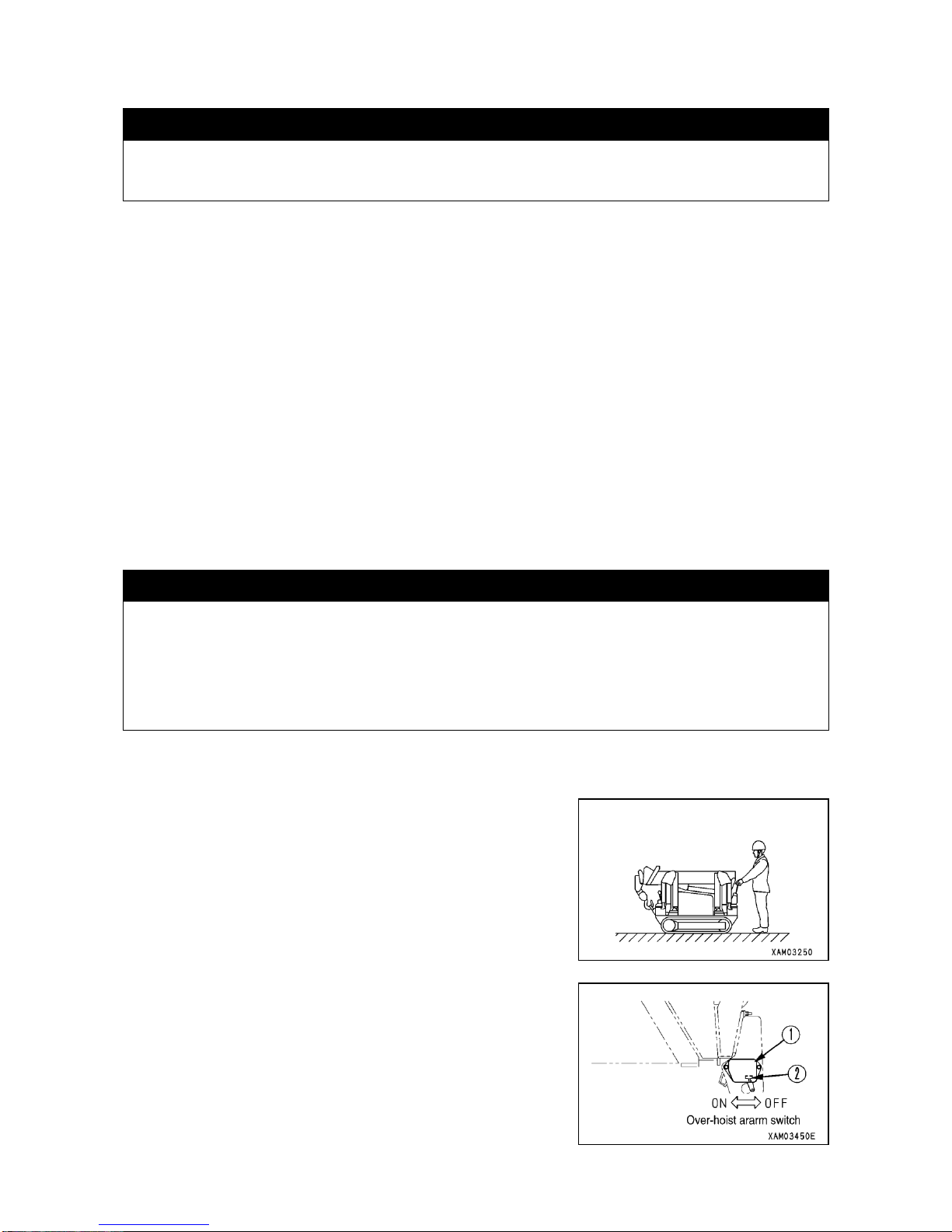
3-28
2.4 BREAK-IN OPERATION
k CAUTION
Perform break-in operation with this machine during the first 20 hours on service meter. Overloading
the machine before various part of machine adapts to operation, may shorten its useful life.
While this machine is shipped after having gone through sufficient adjustment and inspection, forcible operation
during early stage of usage invites pre-matured deterioration in engine or crane performance, resulting in their
shortened useful life. It should undergo break-in operation for the first 20 hours or so on service meter. During the
break-in period, observe following rules in particular:
・After starting up the engine, be sure to perform warm-up run and avoid racing it in accordance with “OPERATION,
2.3 OPERATION AND CHECK AFTER STARTING UP THE ENGINE”.
・Avoid working while overloading it or at high speed.
・Avoid rapid start, rapid acceleration, unnecessary sudden stop or rapid change of traveling direction.
・When break-in period reaches 20 hours, be sure to change engine oil in accordance with “INSPECTION AND
MAINTENANCE, 8.6 [1] ENGINE OIL REPLACEMENT”. Metal particles due to adaptation of engine internals
increase within engine oil to deteriorate the engine oil and shorten the useful life of the engine.
2.5 TRAVEL POSITION OF THE MACHINE
k WARNING
・To move this machine by self-traveling, let the machine assume Travel Position with boom, hook block
and outrigger stowed.
・ Traveling with boom extended or with a load suspended, is prohibited. It may cause tipping over
and serious accident including injury or death.
・ Do not use this machine for other than its primary purpose, such as carrying package placed on it.
・As for driving this machine on public road, see local regulation.
When moving this machine, let it assume travel position as shown in
sketch to the right.
1. Stow the crane and lock the hook block at prescribed location. For
details, see “OPERATION, 2.22 STOWING THE CRANE”.
2. Stow away all the outriggers. For details, see “OPERATION, 2.23
STOWING THE OUTRIGGER”.
3. Turn the switch ② of over-hoist preventive system ① to OFF position.
Page 81
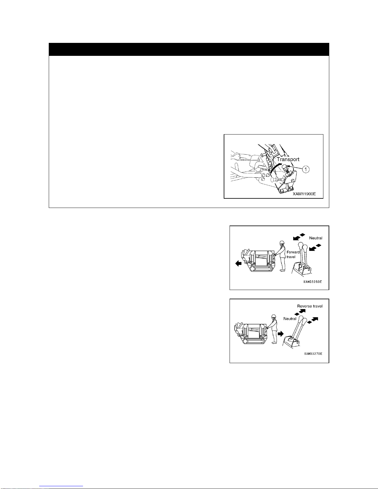
3-29
2.6 STARTING THE MACHINE
k WARNING
・Do not allow any person to approach the machine.
・Remove any obstacle in its traveling path.
Particularly, make sure that the path for traveling backward is free from any hump that may cause
stumbling or any ditch, and improve the terrain.
・This machine is designed so that, simultaneously with starting of the machine, operator is to move
along.
When letting the machine start, adjust the engine to low speed and operate right and left levers
simultaneously and slowly, to check the travel speed of the machine. In case of traveling backward in
particular, avoid abrupt start, which may result in serious accident.
・Immediate front of the machine will become a blind spot. Pay special attention when traveling forward.
・In case your traveling direction is in a blind spot and you can
not make certain of the safety, stop the machine once and
check for the safety before continuing to travel. Place a
guide, depending on the job site situation.
・While traveling, work selector switch should be placed in
Travel position and travel lever locking lever ① in Free
position.
・As for the handle being positioned at the rear end section of
the boom, do not use it for any other purposes than the
traveling purpose.
[1] FORWARD TRAVEL
Operate travel levers, right and left, simultaneously.
・Slowly push the right and left travel levers forward to start.
[2] BACKWARD TRAVEL
Operate the travel levers, right and left, simultaneously.
・Slowly pull back the right and left travel levers to start.
Page 82
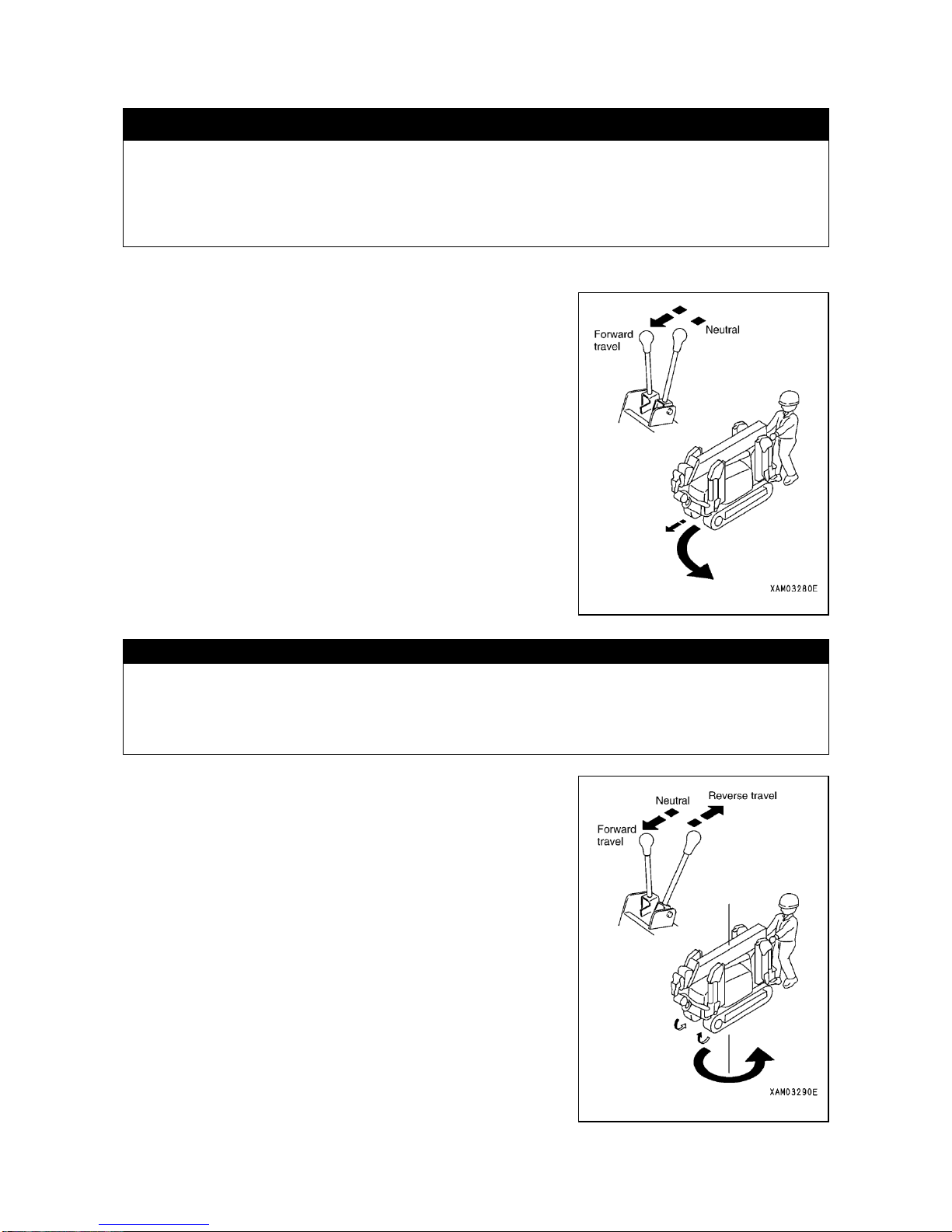
3-30
2.7 CHANGING TRAVEL DIRECTION OF THE MACHINE
k WARNING
・Rapidly changing travel direction at high speed or unnecessary spin turn not only damages rubber
track or hydraulic system, may cause collision with other object. Before making spin turn, bring the
machine to a complete stop and adjust engine to low speed.
・Changing travel direction on slope should be avoided as it is likely to cause a side skidding. Be extra
careful over soft or clay ground.
[1] CHANGING DIRECTION OF THE MACHINE WHILE IT IS STANDING STILL:
・FOR MAKING LEFT TURN:
Operate the travel lever on your right hand side.
Pushing it forward causes the machine to turn left in the direction of
traveling forward.
Pulling it back causes the machine to turn left in the direction of
traveling backward.
・FOR MAKING RIGHT TURN:
Operate the travel lever on your left hand side.
Pushing it forward causes the machine to turn right in the direction of
traveling forward.
Pulling it back causes the machine to turn right in the direction of
traveling forward.
[2] MAKING A SPIN TURN:
CAUTION
・When making a spin-turn, stop the machine once and bring down the engine revolution rate to a low speed level
before operating the machined to make a spin-turn.
・In case the ground surface resistance is high, engine stop troubles may occur. Therefore, operate the machine
after raising the engine revolution gradually when the ground surface resistance is high.
・FOR MAKING A COUNTERCLOCKWISE SPIN TURN:
Pushing right travel lever forward and pulling left travel lever back
simultaneously causes both rubber tracks to rotate in opposite
direction to make counterclockwise spin turn.
・FOR MAKING CLOCKWISE SPIN TURN:
Pushing left travel lever forward and pulling right travel lever back
simultaneously causes both rubber tracks to rotate in opposite
direction to make clockwise spin turn.
Page 83
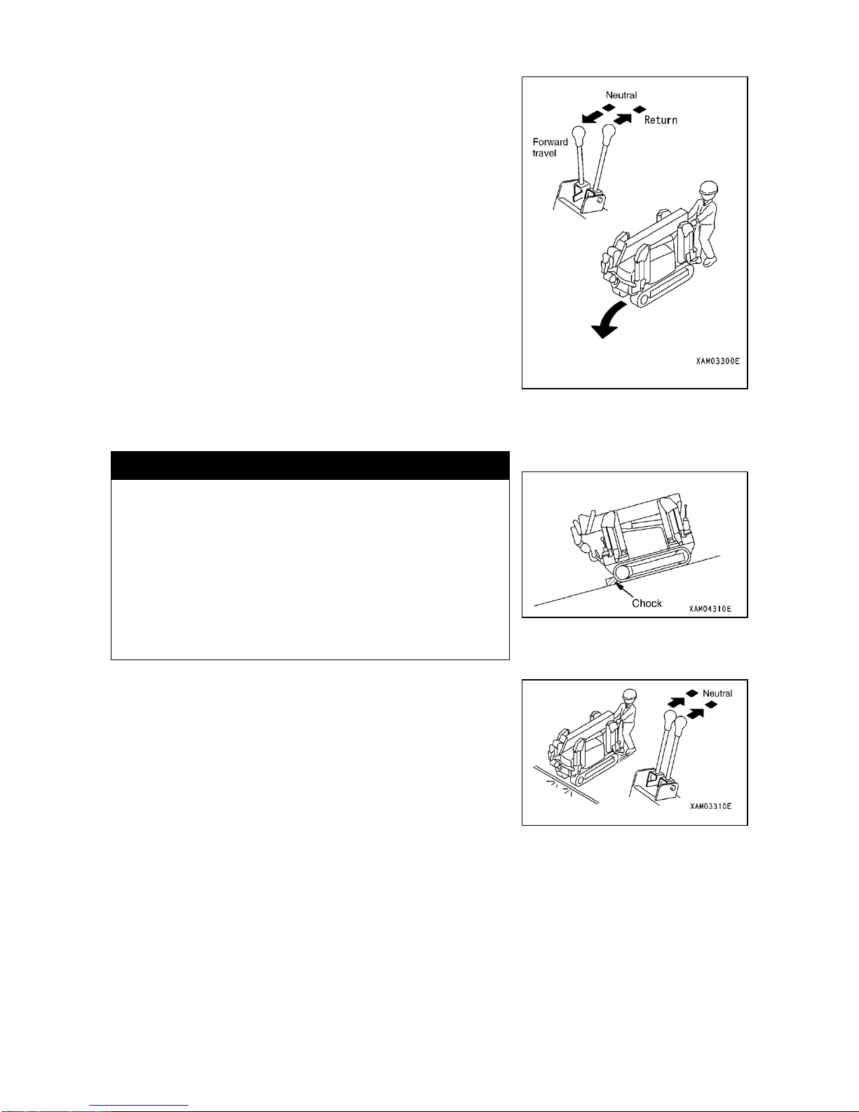
3-31
[3] CHANGING TRAVEL DIRECTION WHILE TRAVELING FORWARD OR BACKWARD:
・FOR MAKING LEFT TURN WHILE TRAVELING FORWARD:
With the right travel lever pushed forward, return only the left travel
lever to Neutral.
・FOR MAKING LEFT TURN WHILE TRAVELING BACKWARD:
With the right travel lever pulled back, return only the left travel lever to
Neutral.
・FOR MAKING RIGHT TURN WHILE TRAVELING FORWARD:
With the left travel lever pushed forward, return only the right travel
lever to Neutral.
・FOR MAKING RIGHT TURN WHILE TRAVELING BACKWARD:
With the left travel lever pull back, return only the right travel lever to
Neutral.
2.8 STOPPING AND PARKING THE MACHINE
k WARNING
・Avoid making sudden stop and bring the machine to stop
slowly where possible.
・Select hard and level ground for parking the machine. If you
have to park it on slope, engage chock to prevent it from
rolling.
・As long as the engine is running, touching the travel lever
carelessly causes the machine to start suddenly to result in
serious accident.
・Before leaving the machine, shutdown the engine and be sure
to remove the main starter key.
Placing both right and left travel levers in Neutral simultaneously, causes
the brake system to be applied automatically for the machine to come to
stop.
Page 84
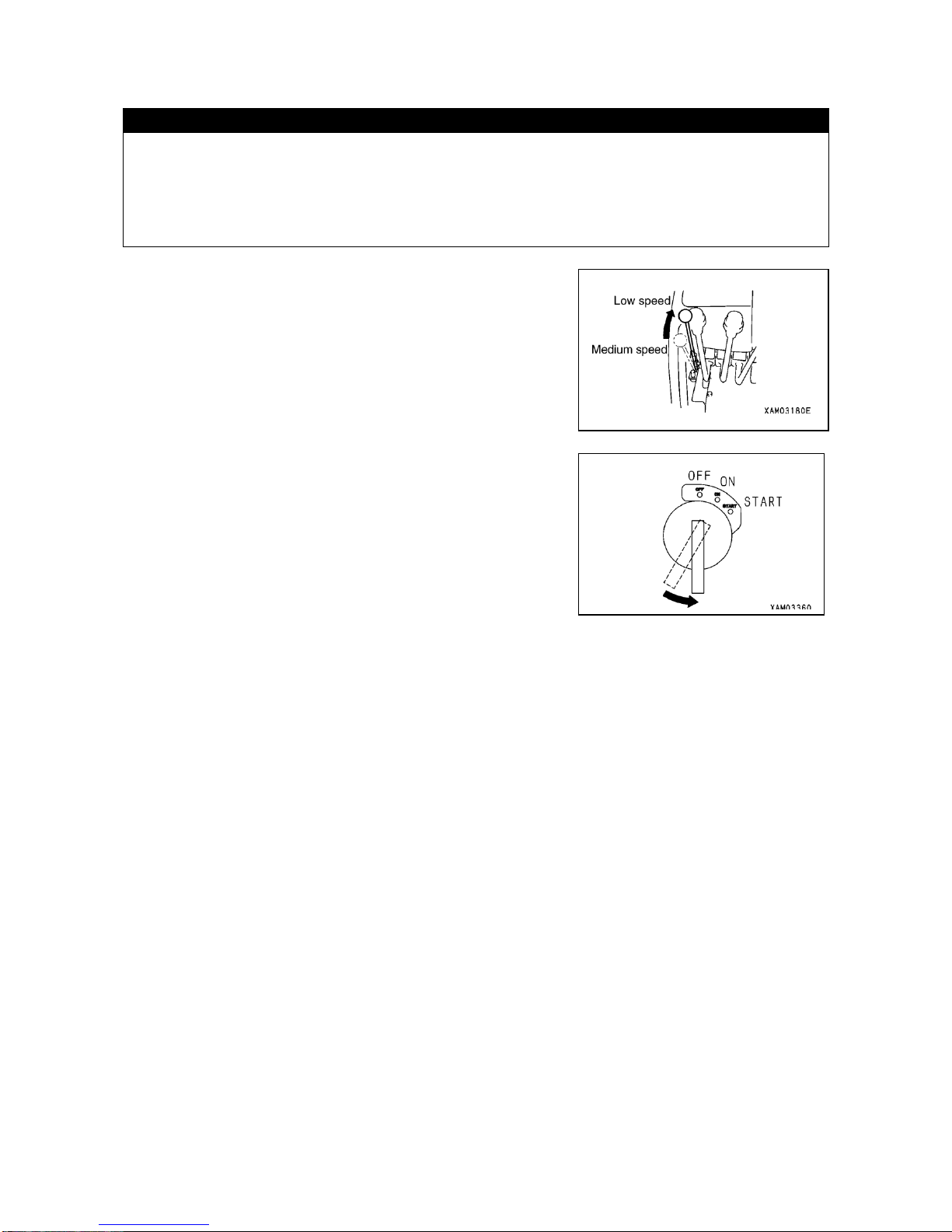
3-32
2.9 STOPPING THE ENGINE
CAUTION
・Stopping the engine before it is sufficiently cooled may shorten useful life of its various part. Do not stop it
abruptly except for emergency.
・When your engine is overheated, do not stop it immediately but run it at medium speed to gradually cool it before
shutting it down.
・Make sure that the main switch in radio control box is in OFF position.
1. Push the accelerator lever forward (all the way to the stroke end) to
place engine at low speed and run it at idling speed for about 5
minutes.
2. Turn the key in main starter switch to OFF position. Engine will stop.
3. Remove the key of main starter switch.
2.10 INSPECTION AND CHECK AFTER STOPPING THE ENGINE
1. Check for oil and water leakage, and visually check undercarriage, crane and other externals.
Correct any abnormality.
2. Fill-up the fuel tank.
3. Fallen leaves or trash deposited around engine should be removed as it may cause fire.
4. Remove dirt deposited around undercarriage and outrigger.
Page 85
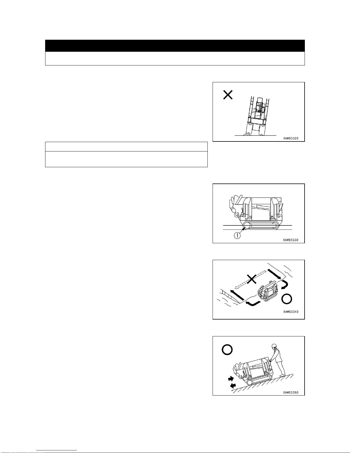
3-33
2.11 RULES FOR TRAVELING
k WARNING
Neglecting these rules for traveling will result in serious accident.
[1] RULES FOR TRAVELING
Climbing over obstacle such as boulder or stump gives the machine
(undercarriage in particular) a great impact and creates the cause for
damage.
Avoid such obstacle or remove it not to climb over it where possible.
When inevitable, be sure to let the machine assume Travel position to
lower its center of gravity and slow down the travel speed as much as
possible, before going over using the center of each track.
NOTES
For details, see “OPERATION, 2.5 TRAVEL POSITION OF THE
MACHINE”.
[2] PERMISSIBLE DEPTH OF WATER
For underwater work, this machine may be used to the depth of the
center of idler ①.
[3] RULES FOR UPHILL OR DOWNHILL OPERATION
・Traveling on any slope steeper than 15 degrees should be avoided as
it may cause tipping over.
・Never attempt to change direction on or while going across slope. Go
down to flat land first or detour for the safety.
・For going downhill, reduce travel speed as much as possible with
combined use of accelerator lever and travel lever.
While placing travel lever in Neutral causes the brake system to be
applied automatically, going downhill at high speed may result in
overrunning.
・For traveling on slope, be sure to position the machine at right angle to
the slope and operator should operate from hill side of the machine.
・If engine stops in the middle of slope, place the travel lever in Neutral
before attempting to start the engine.
Page 86

3-34
2.12 SETTING UP THE OUTRIGGER
k WARNING
・For setting up the outrigger, select hard and level ground where possible. If you must set the outrigger
inevitably on soft ground, place hard plates under the outrigger floats so that the outrigger does not
sink during crane work.
・When setting up the outrigger, do not allow any person to approach it as a serious accident may result,
such as your foot being caught by outrigger.
・When setting up the outrigger, be sure to watch leveling instrument so that levelness of the machine is
secured. Outrigger should be set so that the rubber track is about 50mm off the ground. After setting
up, press each of the four outriggers to make sure that load is being applied evenly.
・While outrigger of this machine can be placed freely in accordance with terrain, in case it is impossible
to place it in "Outriggers extended to maximum" configuration, carry out your crane work in
accordance with the value of "Total Rated Load Chart for Outriggers Extended to other than
Maximum". Further, note that, depending on the outrigger placement angle, there are "crane work
prohibited" zones, wherein your crane work should be avoided.
・Except for during outrigger telescoping operation (such as positioning pin placement or removal),
work should be performed with the engine shutdown.
If any outsider should inadvertently touch the outrigger switch, the outrigger cylinder may suddenly
actuate and a serious accident may result.
・Before placing the outriggers, insert each positioning pin completely and retain it securely by
engaging snap pins.
・Whenever you place the outrigger, do not fail to extend the outrigger top box.
Do not extend outriggers with the top boxes remaining stowed.
・This machine has 4 outriggers. Be sure to use individual outrigger correctly. Check the relations
between the numbers shown on Instruction Plate at the switch and number plate affixed on each
individual outrigger. Incorrect operation can result in a serious accident.
・When you operate two outrigger switches simultaneously, operate two for front ([①]and [④]) and two
for rear ([②] and [③]). Operating two switches of left and right side simultaneously may cause the
machine to tip over.
・For floating the machine off ground. operate four outrigger switches in such manner as the four
outriggers go up evenly and bit by bit. Floating rapidly with two outriggers on one side may cause the
machine to tip over.
・When operating the outriggers, run the engine at low speed. Leaving the engine at high revolution
may cause the outrigger to actuate suddenly, inviting serious accident including tipping over of the
machine.
・When operating the crane or the outriggers setting the travel lever stand to the “CRANE POSITION”,
do not touch the travel lever since the undercarriage will move if you touch the travel lever and it will
be very dangerous.
・When operating the outriggers by use of the remote control, be careful not to let the remote control
cable touch the rubber track.
CAUTION
・Before operating outrigger switch, push down the travel lever at travel control to place the locking lever in Crane
Work position.
So long as the locking lever remains in Travel position with the travel lever stand pushed forward, the outrigger
is actuated only at very slow speed even if the outrigger switch is operated.
・When you disengage hook block from its hanger, do not excessively loosen the wire rope to such extent that the
whole hook block lies down on the ground. It will be a cause for disorderly take up on the winch drum.
・Operating the outrigger switch causes outrigger mode indicator lamp to go on and warning buzzer to generate
intermittent sound.
・Operating the outrigger switch causes the crane lever to move simultaneously, which does not represent any
trouble.
Page 87
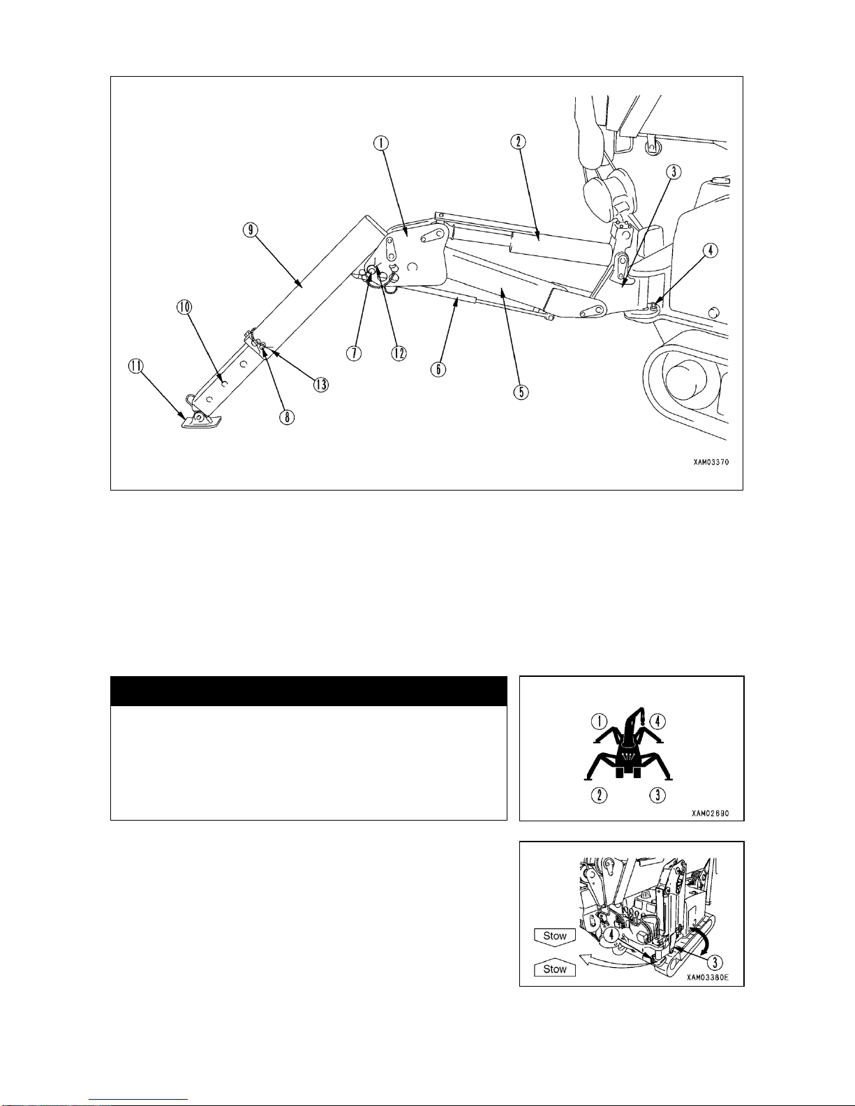
3-35
[1] COMPONENTS OF OUTRIGGER
① Linkage bracket
② Outrigger cylinder
③ Rotary
④ Rotary position pin
⑤ Outrigger base box
⑥ Stay (Damper type)
⑦ Outrigger top position pin
⑧ Inner box position pin
⑨ Outrigger top box
⑩ Inner box
⑪ Float
⑫ Snap pin
⑬ Snap pin
[2] STEPS TO BE PERFORMED WITH THE ENGINE SHUTDOWN
k WARNING
When placing outriggers to maximum, the holes of rotary ③ to
insert positioning pins ④ are different for the set of outriggers
[①] and [②] and that of [③] and [④].
Read this section carefully to place the outriggers properly. In
this section, steps to place the outriggers to maximum is
presented.
This machine has 4 outriggers. Method for setting up the outrigger is
described below for the [Outrigger ③] only. The same applies to other 3
outriggers as well.
1. Withdraw position pin ④ of rotary ③ and rotate the rotary outward.
Page 88
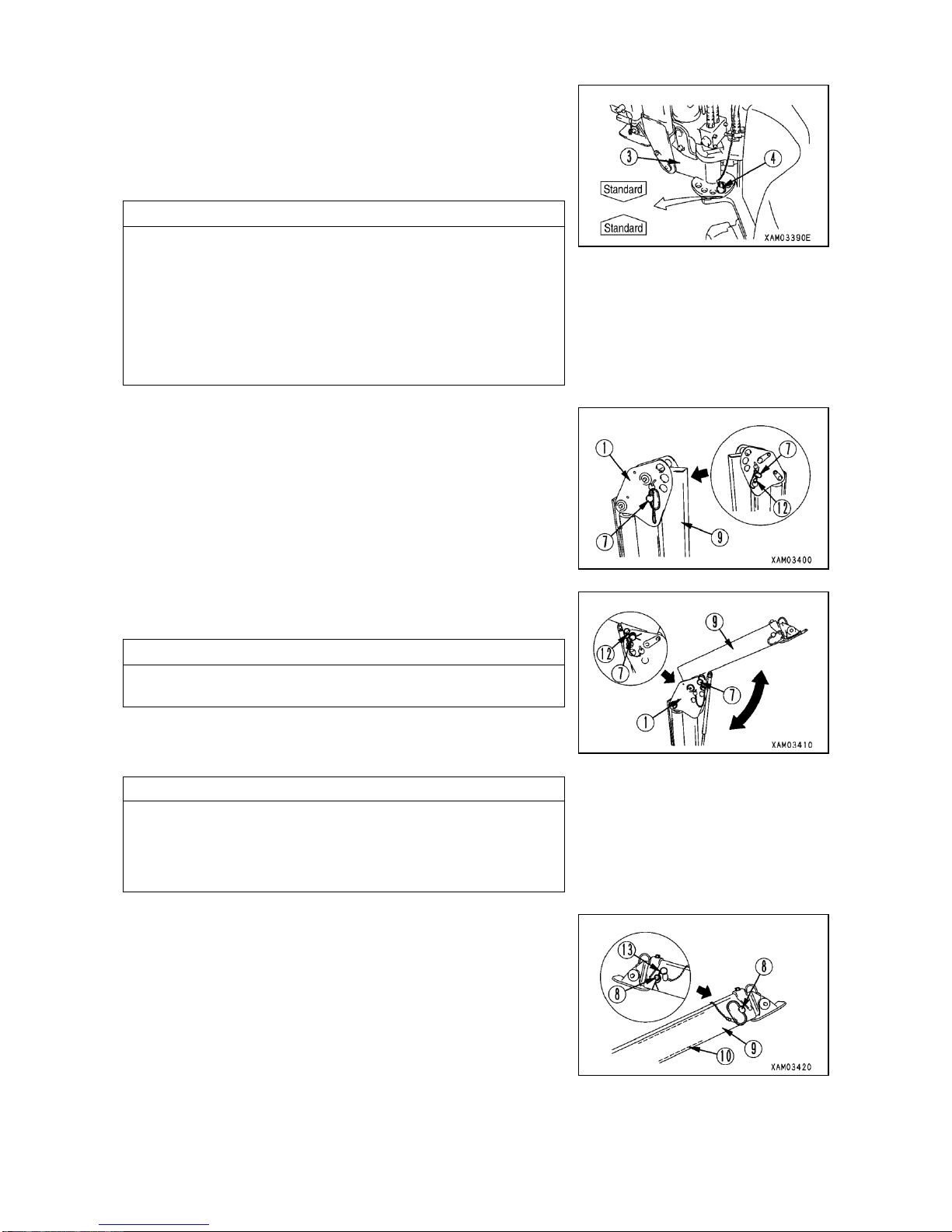
3-36
2. Turn the rotary ③ so that the sticker "Standard" affixed to its side and
the sticker "Standard" affixed to the side of frame are aligned.
3. Insert positioning pin ④ to the hole where the stickers “Standard” are
aligned.
NOTES
・Positioning pin ④ has a ball chain for prevention of loss.
Make sure that the ball chain is not caught by or crossing the top of
frame. If it is, the positioning pin ④ will not go all the way into the pin
hole of rotary ③ and may come off.
・If any hole other than where stickers "Standard" meet is being
utilized, outrigger extension should be regarded as "OTHER THAN
STANDARD EXTENSION". In this position, there are "WORK
PROHIBITED ZONES" and working within should be avoided.
4. Remove snap pin ⑫ at the end of positioning pin ⑦ of linkage bracket
① and pull out the pin ⑦.
5. Lift up the top box ⑨ and align the hole of top box ⑨ with the position
of the outermost hole on linkage bracket ①.
NOTES
The position of outermost hole on linkage bracket, means the one that
has the sticker "Maximum Extension" affixed to it.
6. Insert the positioning pin ⑦ to the outermost hole on linkage bracket
① and retain it with the snap pin ⑫ at its end.
NOTES
When the outrigger is set with the pin inserted to any hole other than
that of sticker “Maximum Extension” of the linkage bracket, work
should be perfomed in accordance with “TOTAL RATED LOAD
CHART WITH OUTRIGGER EXTENDED TO OTHER THAN
MAXIMUM".
7. After removing the snap pin ⑬ at the end of positioning pin ⑧ of top
box ⑨, pull out the positioning pin ⑧.
Page 89
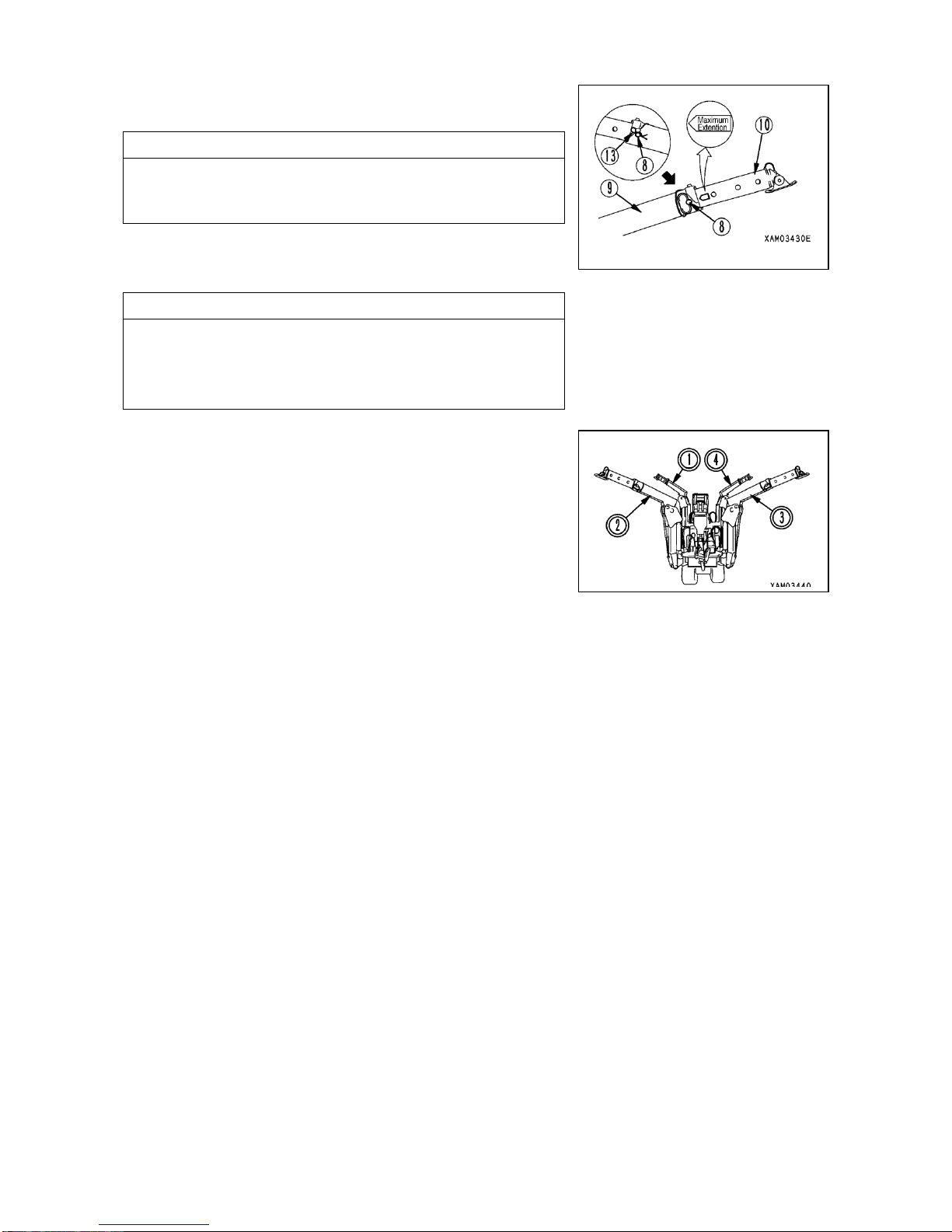
3-37
8. Pull out the inner box ⑧ from top box ⑨ and align the hole on top box
⑨ with the position of innermost hole on the inner box ⑩.
NOTES
The position of innermost hole on inner box, means the one that
meets the top box hole when the sticker "Maximum Extension" affixed
to the side of inner box is totally exposed.
9. Insert the positioning pin ⑧ to the hole of top box ⑨ and retain it with
the snap pin ⑬ at its end.
NOTES
When the outrigger is set with the pin inserted to any hole other than
that of sticker “Maximum Extension” of the inner box, work should be
performed in accordance with “TOTAL RATED LOAD CHART WITH
OUTRIGGER EXTENDED TO OTHER THAN MAXIMUM".
10. Prepare other three outriggers in the same manner.
11. After completion of this preparation work, make sure that positioning
pins are securely inserted to each hole with retainers engaged.
Page 90
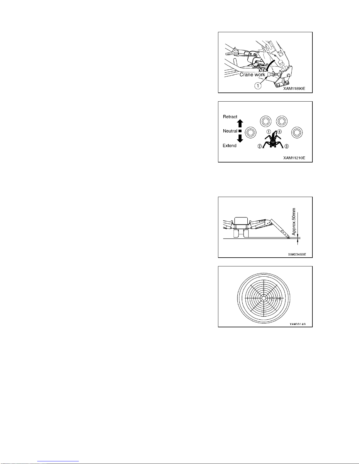
3-38
[3] WORKS TO BE DONE AFTER STARTING ENGINE
1. Start the engine. For details, see “OPERATION, 2.2 STARTING UP
THE ENGINE”.
2. Push down the travel lever stand and place the locking lever ① in
Crane Work position.
3. Check the number on instruction plate of outrigger switch and decide
the outrigger you desire to actuate.
4. Push the accelerator lever forward to run the engine at low speed.
5. Push down the outrigger set up switch individually or two at a time.
When the set up cylinder is extended for the float to be grounded,
place the switch at Neutral. Operate other switches in the same
manner so that floats of all the four outriggers are grounded before
placing each switch at Neutral.
6. After grounding all the floats, push the outrigger set up switch
individually or two at a time. When the machine is slightly lifted with
the set up cylinders extended, place the switch at Neutral. Operate
other outriggers in the same manner so that 4 outriggers are lifted to
the same height and place the switch at Neutral. Repeat this
operation to gradually lift the machine off the ground until the rubber
track is at 50mm high.
7. When the machine reaches about 50mm off the ground, while
watching leveling instrument, operate the outrigger set up switches
until the machine is level.
8. Upon completion of outrigger setting, place all the outrigger switches
at Neutral.
Page 91
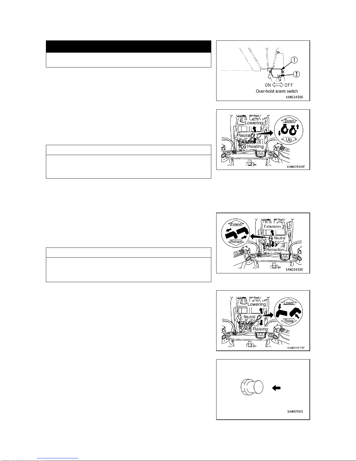
3-39
2.13 MATTERS TO BE KNOWN BEFORE STARTING CRANE WORK
k WARNING
Negligence of following matters may lead to serious accident.
・Place the switch ② of over-hoist preventive system ① at ON position.
If this switch is in OFF position, the alarm will not sound even when
the hook block is over-hoisted.
・Over-hoisting the hook block causes the warning buzzer of over-hoist
preventive system to sound.
If the buzzer sounds, release the winch lever immediately to have it
return to Neutral and stop hoisting.
NOTES
Even if the warning buzzer sounds, motion of winch hoist or boom
raise does not stop. Be sure to place the lever in Neutral to stop the
motion.
After that, push the winch lever forward to Lower position and lower
the hook block.
・Extending the boom causes the hook block to be hoisted and buzzer of
over-hoist preventive system to sound.
If the buzzer sounds, release the boom telescoping lever and let it
return to Neutral so that the motion of boom extension stops.
NOTES
Even if the warning buzzer sounds, motion of winch hoist or boom
raise will not stop. Be sure to place the lever in Neutral to stop the
motion.
After that, pull back the boom telescoping lever to Retract position and
retract the boom.
Likewise, if boom is hoisted, hook block will be hoisted and buzzer of
over-hoist preventive system will sound
If the warning buzzer sounds, release the Boom derrick lever
immediately so it returns to Neutral and the boom raise action stops.
・During crane work, if you need to warn the surroundings about the
danger, press horn switch to sound the horn.
・Make sure that all the outriggers are extended properly.
Page 92
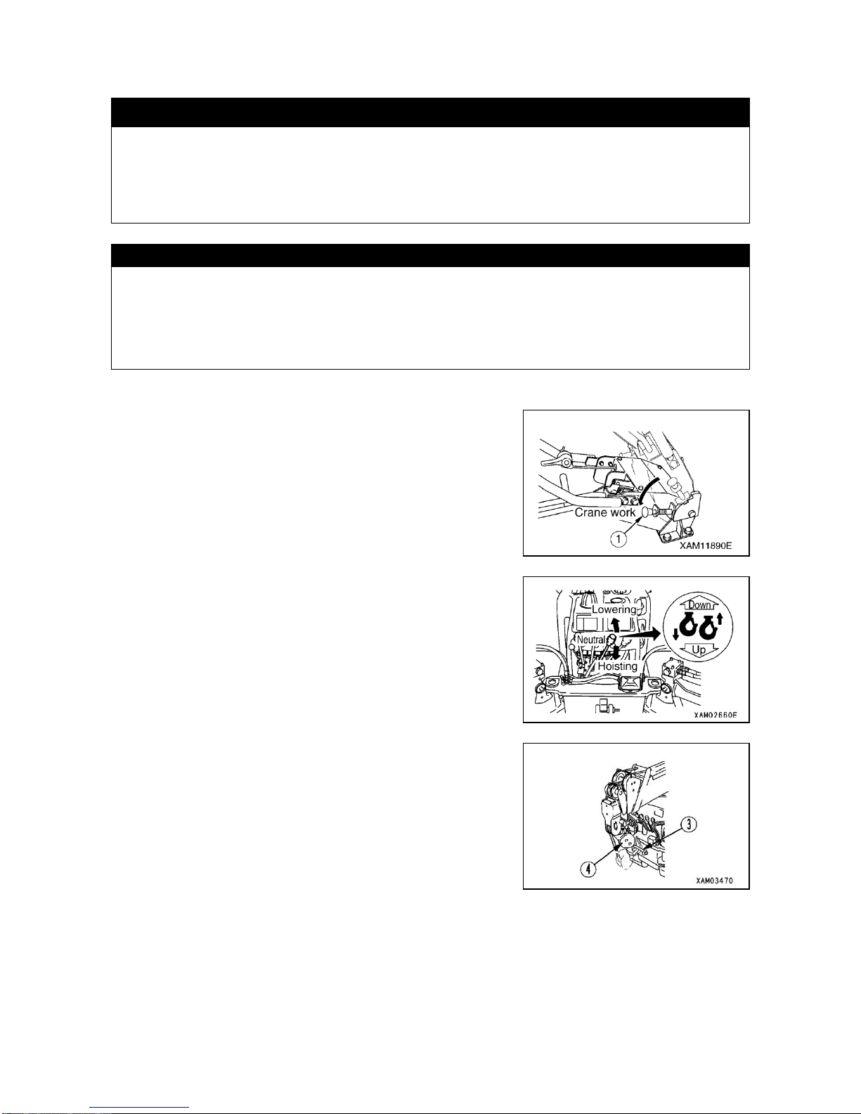
3-40
2.14 OPERATIONS PRIOR TO STARTING CRANE WORK
k WARNING
・When operating the crane or the outriggers setting the travel lever stand to the “CRANE POSITION”,
do not touch the travel lever since the undercarriage will move if you touch the travel lever and it will
be very dangerous.
・When operating the outriggers by use of the remote control, be careful not to let the remote control
cable touch the rubber track.
CAUTION
・Before operating various crane control levers or outrigger switches, push back down the travel lever stand on the
side of travel control and place the locking lever in Crane Work position. If the travel lever stand is pushed
forward and locking lever is placed in Travel position, any of these control levers or outrigger switches will not
actuate.
・When lowering hook block from stowed location, do not allow the whole hook block to lie on the ground by
loosening the wire rope excessively. It constitutes the cause for disorderly take-up on winch drum.
Before proceeding to your crane work, take the following steps:
1. Push back down the travel lever stand and place the locking lever ①
at Crane position.
2. Move the winch lever to Lower position to loosen the wire rope which
has been locking the hook block.
3. Disengage the hook block ④ from its hanger ③.
Page 93
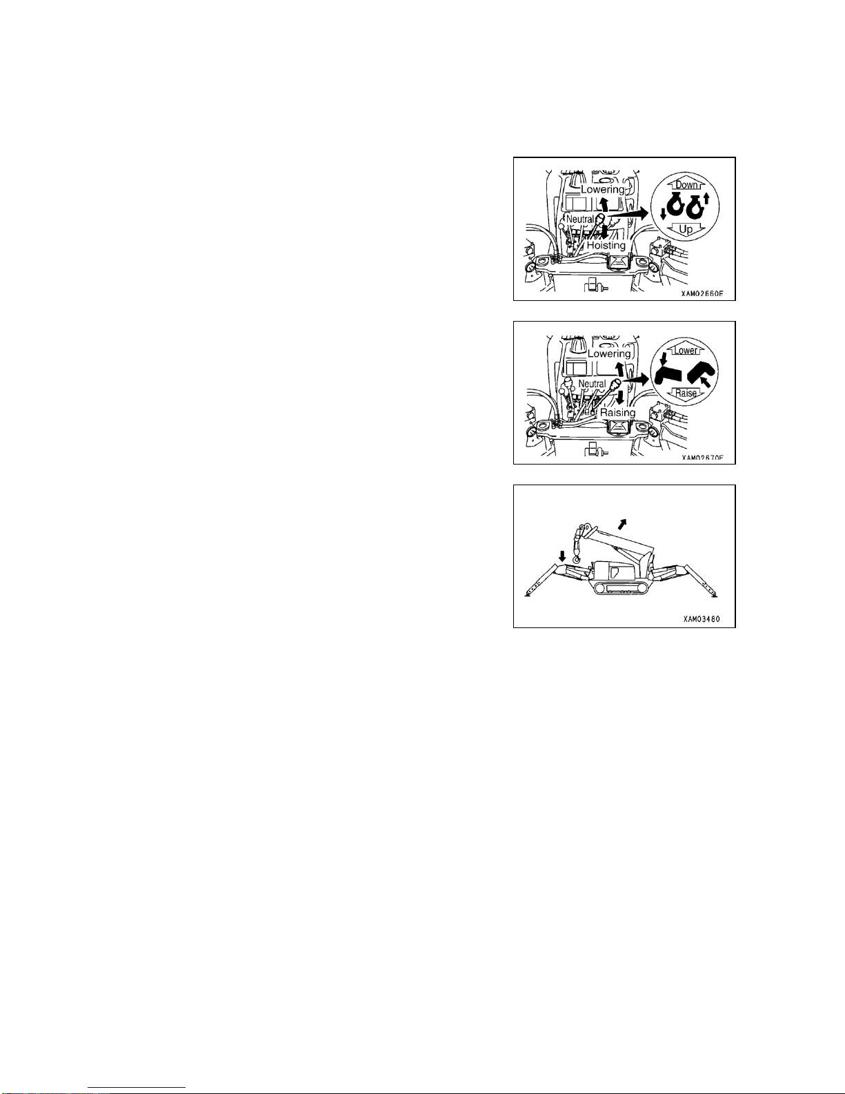
3-41
2.15 CRANE WORK POSITION
Upon completion of “OPERATIONS PRIOR TO STARTING CRANE
WORK” in preceding section 2.14, let the machine assume “CRANE
WORK POSITION” in the following manner:
1. Operate the winch lever downward to Lower position and lower the
hook block to the extent that it is not grounded.
2. Operate the Boom derrick lever to Hoist position and hoist the boom
to such angle where hook block is not over-hoisted or grounded.
Page 94
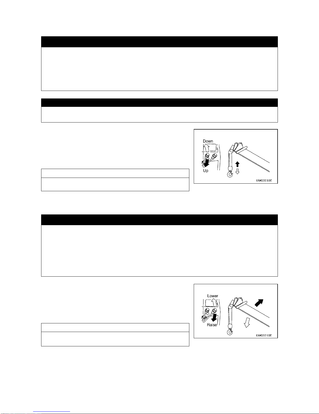
3-42
2.16 HOISTING AND LOWERING OPERATION
k WARNING
・When lifting a load, the load will move slightly forward due to bending of the boom. Wiring personnel
should be aware of this.
・Over-hoisting the hook block causes the over-hoist alarm buzzer to sound.
If the buzzer sounds, immediately place the winch lever in Neutral to stop hoisting.
・When you lower the hook way down for underground work or the like, you should leave the wire rope
at least 3 windings on the drum.
CAUTION
Do not ground the hook block. It may cause wire rope to be wound disorderly on the drum to cause damage.
Operate the winch lever in the following manner:
・Lowering: Push the lever forward to Lower position.
・Neutral: Take your hand off the lever. Lever will return to Neutral
position and hoisting or lowering of the hook block will stop.
・Hoisting: Pull back the lever to Hoist position.
NOTES
Adjust the winch hoisting or lowering speed with the stroke of winch
lever and accelerator lever.
2.17 BOOM DERRICKING OPERATION
k WARNING
・Boom derrick lever should be operated as slowly as possible. Rapid lever operation particularly with a
load lifted, will cause the load to sway and machine to incur big shock, resulting in damaging the
crane or tipping it over.
・When hook block is hoisted in excess, over-hoisting is detected causing the horn and voice to sound.
When you hear the horn and voice, immediately return the winch lever to neutral to stop hoisting.
・Lowering the boom causes the working radius to increase and liftable total rated load to reduce. When
you work while raising or lowering the boom, use care that the mass (weight) of load does not cause
over-loading when the boom is lowered.
Operate the Boom derrick lever in the following manner:
・Lowering: Push the lever forward to Lower position.
・Neutral: Take your hand off the lever. Lever will return to Neutral
position and hoisting or lowering of the boom will stop.
・Rising: Pull back the lever to Raise position.
NOTES
Adjust the boom Rising or lowering speed with the stroke of boom
derrick lever and accelerator lever.
Page 95
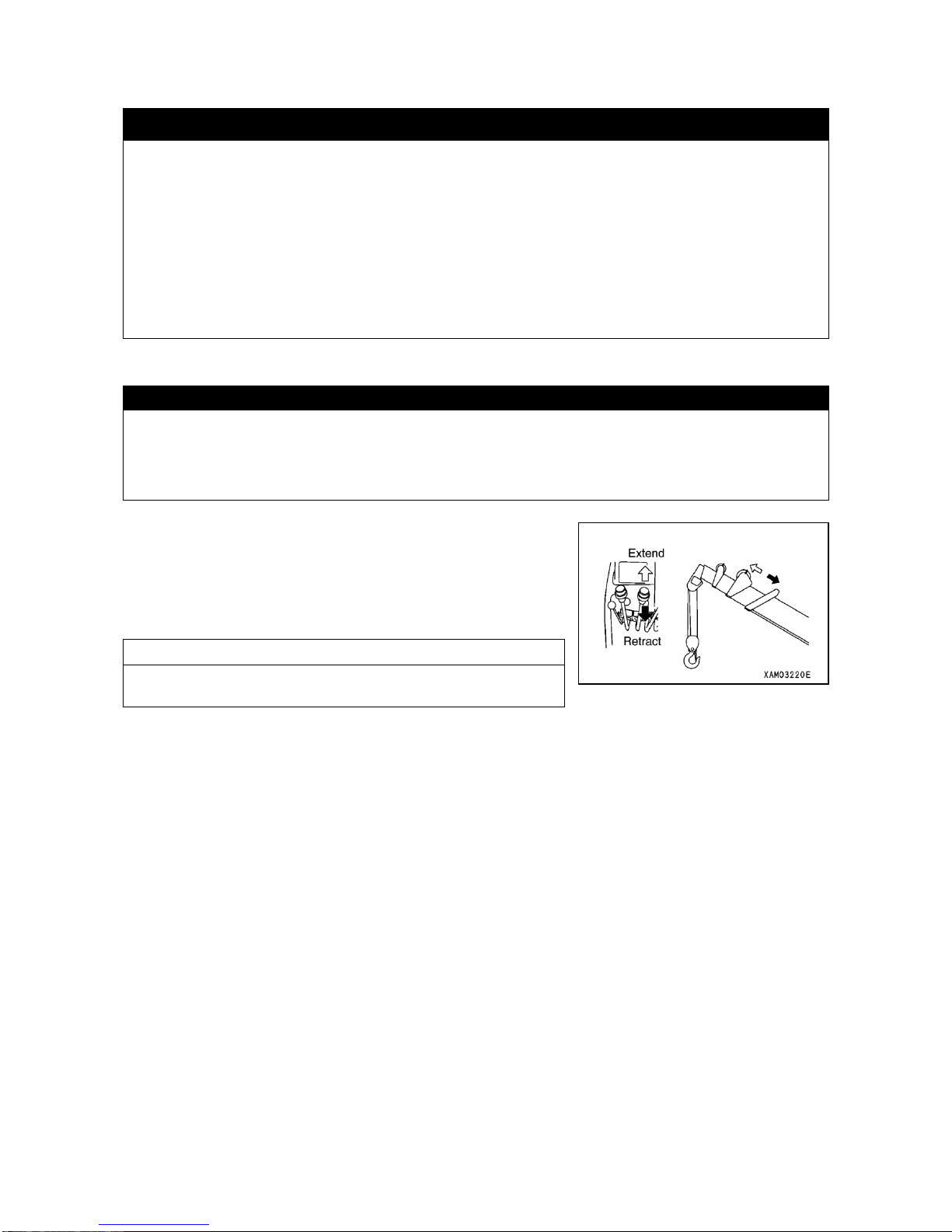
3-43
2.18 BOOM TELESCOPING OPERATION
k WARNING
・Operate the boom telescoping boom as slowly as possible. Rapid lever operation particularly with a
load lifted, will cause the load to sway and machine to incur big shock, resulting in damaging the
crane or tipping it over.
・Do not use boom telescoping action for dragging a load laterally or pulling it in.
・Extending the boom causes the working radius to increase and the liftable total rated load to reduce.
When you work while telescoping the boom, use care that the mass (weight) of load does not cause
over-loading when the boom is extended to the maximum.
・While the boom is being extended, hook block will keep being hoisted. If the over-hoist preventive
device buzzer sounds while you are extending the boom, place the boom telescoping boom in
Neutral immediately to stop telescoping of the boom.
CAUTION
・While the boom is being telescoped, the hook block will keep either being hoisted or lowered. Winch should be
operated simultaneously to keep the hook block height adjusted.
・Leaving the boom extended for long time causes the boom to slightly to retract due to change in hydraulic oil
temperature or the like. In such a case, boom length should be adjusted appropriately.
Operate the boom telescoping lever in the following manner:
・Extending: Push the lever forward to Extending position.
・Neutral: Take your hand off the lever. Lever will return to Neutral
position and telescoping of the boom will stop.
・Retracting: Pull back the lever to Retract position.
NOTES
Adjust the boom telescoping speed with the stroke of boom
telescoping lever and accelerator lever.
Page 96
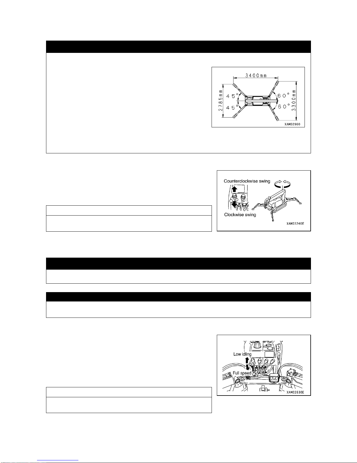
3-44
2.19 SWING OPERATION
k WARNING
・Before making swing motion, be sure to ascertain the safety of surrounding by sounding the horn.
・Swing lever should be operated as slowly as possible.
・Always to try to start smoothly, swing at low speed and stop
gently. Rapid lever operation with a load lifted will cause the
load to sway and machine stability to be lost, resulting in
damaging the crane or tipping it over.
・ For swinging 360 degrees with a load lifted, always place
outriggers in standard extending direction as shown to the
right.
Note that, even with the outriggers extended to maximum,
lateral stability is not necessarily perfect.
・If it is difficult to extend outriggers in such configuration as
shown to the right, make sure of the positions where certain
load can be lifted and where not, before starting to lift.
Operate the swing lever in the following manner:
・Counterclockwise swing: Push the lever forward to Left position.
・Neutral: Take your hand off the lever. Lever will return to Neutral
position and the swing motion will stop.
・Clockwise swing: Pull back the lever to Right position.
NOTES
Adjust the swing motion speed with the stroke of swing lever and
accelerator lever.
2.20 ACCELERATOR LEVER OPERATION
k WARNING
It is dangerous to increase speed of any crane action rashly.
CAUTION
At the start or near the end of any action, reduce speed. Also adapt high or low speed to the load you are actually
lifting.
Operate the accelerator lever in the following manner:
・Low idling: Push the lever all the way forward. Pushing the lever
forward causes the engine speed to drop and various
crane motion also to be slowed down.
・Full speed: Pull the lever all the way back. Pulling back the lever
causes the engine speed to increase and various crane
motion also to so faster.
NOTES
Release lever at the position of desired engine speed. Lever will stop
right there.
Page 97
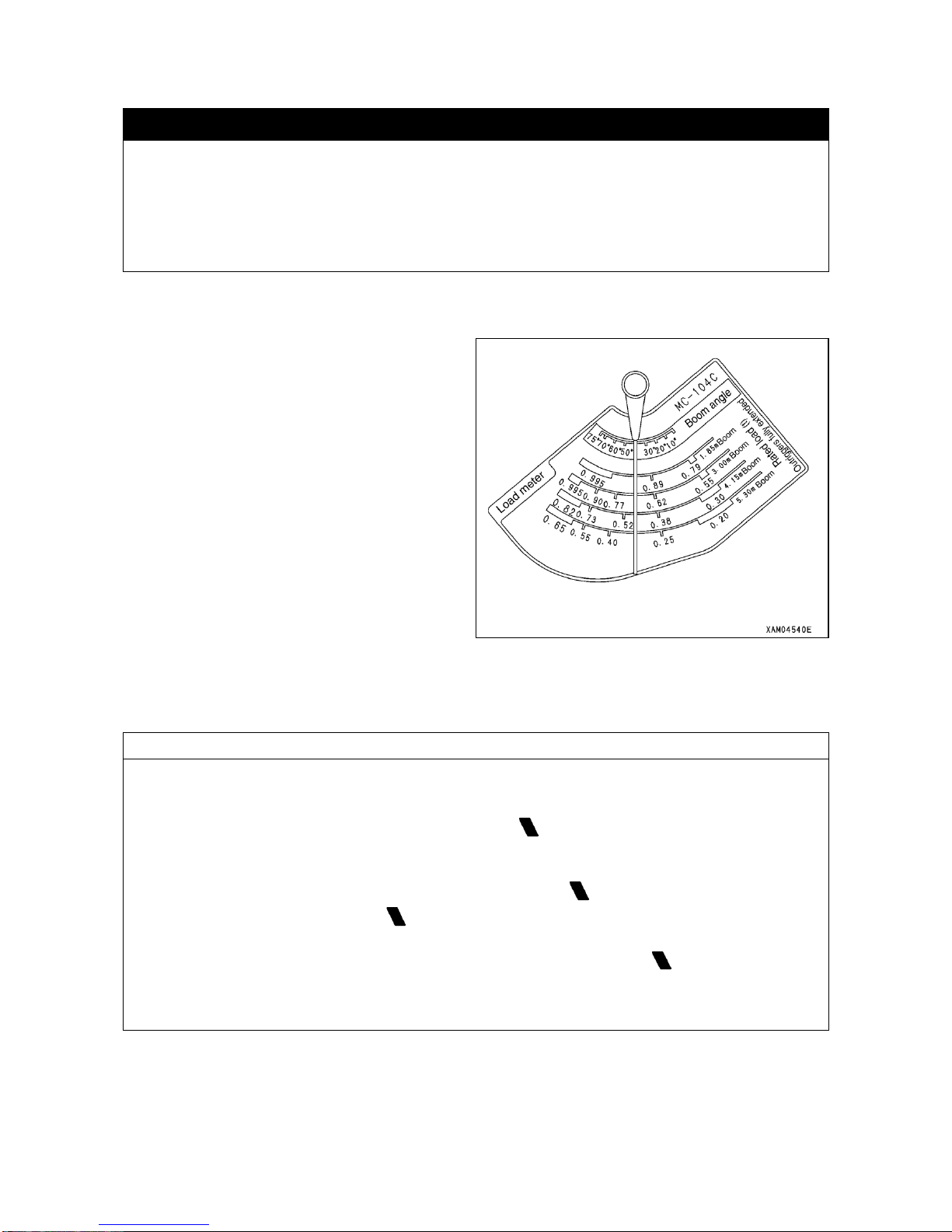
3-45
2.21 HOW TO USE LOAD INDICATOR AND LOAD METER
k WARNING
・Understand how to use the load indicator and load meter so you can perform your crane work safely,
not exceeding total rated load.
・When you lift a load, if the pointer of load meter should exceed such total rated load as is read on load
indicator, the load should be grounded immediately. Continuing to lift as it is, may cause the machine
to be damaged or tipped over.
・If a load exceeds total rated load, reduce the working radius by either shortening the boom or hoisting
the boom.
[1] USAGE OF LOAD INDICATOR AND LOAD METER WITH “OUTRIGGER EXTENDED TO
MAXIMUM”
For performing crane work, read the total rated load on
the load indicator and mass (weight) of the lifting load
on the load meter in the following manner: Incidentally,
the total rated load includes mass (weight) of hook
block, 0.015 ton.
1. Operate boom derrick lever to hoist the boom before
stopping at desired angle.
2. The boom angle should be read as the value where
the column メBoom Angleモ on the load indicator and
pointer crosses each other.
3. Operate boom telescoping lever to extend the boom
to desired length.
4. The total rated load should be read as the value
where the メScale of Boom Length in Useモ in the
column “TOTAL RATED LOAD WITH OUTRIGGER
EXTENDED TO MAXIMUM” on the load indicator
and the pointer crosses each other.
NOTES
"Scale of Boom Length in Use" in the column of the Total Rated Load with Outrigger Extended to Maximum
represents following cases:
・"1.85m Boom": All booms retracted.
・"3.00m Boom": Boom is extended to such extent that the first mark on the boom ② is exposed. In case the
boom ② is extended by any length also, the work should be carried out according to the performance of this
column.
・"4.15m Boom": Boom ② is extended to such extent that the second mark on the boom ② is exposed.
In case more than one-half of the first mark on the boom ② is exposed also, the work should be carried
out on the basis of the performance of this column.
・"5.30m Boom": All booms are extended fully. In case more than one-half of the first mark on the boom ② is
exposed also, the work should be carried out according to the performance of this column.
* For the detail of Boom Length in Use, see “INTRODUCTION, 5.3 HOW TO READ TOTAL RATED LOAD
CHART”.
Page 98
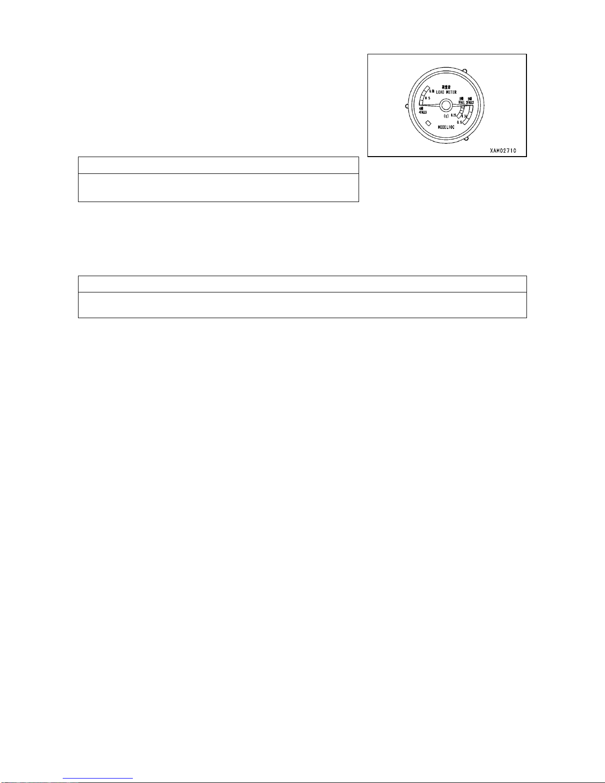
3-46
5. While watching the lifting load and load meter, read the value on the
load meter immediately after the load lifts off the ground (lift off).
The load should be detected in the following manner:
(1) Operate the winch lever to lift the hook block with no load engaged
(no-load).
(2) Operate the accelerator lever to adjust engine speed so that the
pointer of load meter indicates zero (0).
NOTES
Remember the position of the accelerator lever at this time.
(3) Engage the lifting load with hook block and adjust engine speed to the value acquired in preceding paragraph
(2).
(4) Operate the winch lever and read the value indicated by the pointer of load meter immediately after the load
lifts off the ground (lift off).
NOTES
It should be noted that the load meter indicates the weight of load being hoisted with winch only, but it does not
indicate weight of load being lifted by any other means.
6. If the mass read on the load meter is less than such メTotal rated loadモ of load indicator as was read with step (4)
above, your crane work will be safe.
[2] HOW TO USE LOAD INDICATOR WITH OUTRIGGER EXTENDED TO MIDWAY OR MINIMUM:
When you work with outrigger configuration other than maximum extension, read the boom raise angle by means of
load indicator and based on such angle, read the working radius by means of Working Radius/Lifting Height Chart,
and then read the load shown in the Total Rated Load Chart for other than Outrigger Extended to Maximum.
Suppose the boom angle which is read on load indicator is 40 degrees, read the value of total rated load in the
following manner:
1. Read the working radius on the Working Radius/Lifting Height Chart for the case of boom length 4.15m and
boom angle 40 degrees. The working radius for this case will be about 3.1m.
2. Read the value of total rated load from the Total rated load Chart for other than Outrigger Extended to Maximum,
for the case where working radius is about 3.1m as read in the preceding subparagraph 1 for the boom length of
4.15m.
In case the working radius is about 3.1m, the total rated load of 140kg for the working radius 3.5m on the total
rated load chart, will be the total rated load.
3. Read the weight of lifting load and if it is less than Total rated load, your work will be safe.
Page 99
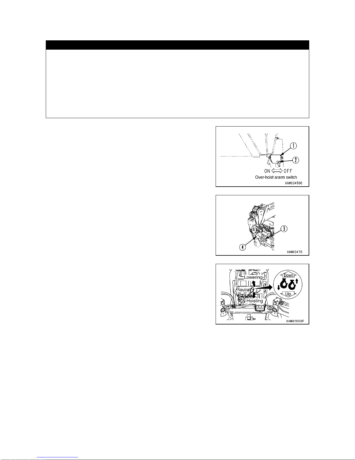
3-47
2.22 STOWING THE CRANE
CAUTION
・Before lowering and engaging the hook block to its hanger, stop the swaying of the block.
・Before engaging the hook block to its hanger, do not loosen the wire rope excessively to avoid the whole hook
block to lie down on the ground. It will be a cause for disorderly take up on the winch drum.
・When securing the hook block, do not tighten the wire rope excessively. It may damage wire rope or locking
metalwork for the hook engagement. Insufficient tension may also cause the hook block to sway during travel
and damage surroundings with interference.
・Retracting the boom places the hook block in such condition as if it were lowered. Also, lowering the boom
causes the hook block to be lowered. To prevent the hook block from grounding or interfering with the machine,
hoisting action should also be performed simultaneously.
1. Have the boom totally retracted.
2. Have the boom lowered all the way.
3. Place the switch ② of over-hoist preventive system ① in OFF position
to stop the buzzer sounding.
4. Push the winch lever forward to Lower position and engage the hook
portion of hook block ④ to its hanger ③.
5. Pull back the winch lever and place it in Hoist position to hoist the hook
block. Wire rope will pull the hook block so that the entire crane is
secured.
Page 100
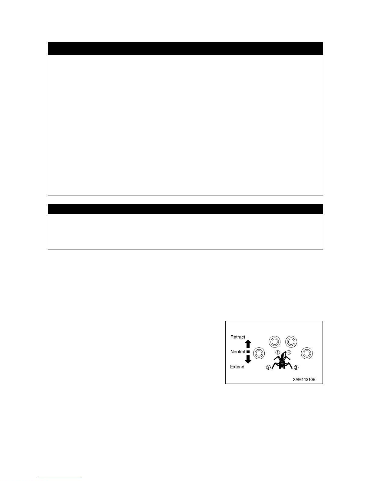
3-48
2.23 STOWING THE OUTRIGGER
k WARNING
・When stowing the outrigger, do now allow anyone to approach. Serious accident may result, such as
being caught between the outrigger and basic machine.
・Any work other than outrigger cylinder extension and grounding, should be carried out with the engine
shutdown. If someone inadvertently touches the outrigger switch, outrigger cylinder will actuate
suddenly causing serious accident.
・Removing position pins causes box and bracket to rotate as they lose support. Be sure to hold them
with single hand before pulling out position pins.
・When stowing the outrigger, do not allow your hand or finger to approach any gap of moving part. It
may lead to serious accident such as being caught.
・To stow the outrigger, insert each positioning pin completely and retain them securely by means of
snap pins.
・This machine has 4 outriggers. Do not mix up the use of 4 outriggers. Check the numbers shown on
control plate at the switch with the number plates affixed to each outrigger. Improper operation will
result in serious accident.
・When operating the outrigger, run the engine at low speed. Leaving it running at high speed causes
sudden actuation of outrigger, resulting in serious accident including tipping over of the machine.
・When you lower floated machine to ground, operate 4 outrigger switches so that all the 4 outriggers
are lowered evenly in small increments. Rapidly retracting 2 outriggers on one side causes the
machine to be unstable and even to tip over.
CAUTION
・Operating the outrigger switch causes the outrigger mode indicator lamp to flash and warning buzzer to
generate intermittent sound.
・Operating the outrigger switch causes the crane control lever to move simultaneously, which does not represent
any trouble.
[1] PROCEDURES TO BE PERFORMED AFTER STARTING THE ENGINE
1. Start the engine. For details, see “OPERATION, 2.2 STARTING UP
THE ENGINE”.
2. For operating the outrigger, place the work selector switch at
Outrigger position.
3. Push up the outrigger set up switch, one of them at a time or two
simultaneously, to ON position.
When, with the outrigger retracting, the machine starts to lower, place
the switch in Neutral for the time being.
Operate the remaining switches in the same manner so that 4
outriggers rise to equal height, place switches in Neutral for the time
being.
Repeat this operation to lower the machine gradually, until the rubber
tracks are totally grounded.
 Loading...