


584E-OM0912-02
OPERATION MANUAL
CRAWLER CRANE
Serial No. 8009 and up
Unsafe use of this machine may cause serious injury or death. Operators
must read this manual before operating this machine. This manual should
be kept near the machine for reference and periodically reviewed by all
personnel who will come into contact with it.
NOTICE
MAEDA has Operation Manual written in some other languages. If a foreign
language manual is necessary, contact your local distributor for availability.


0-1
CONTENTS
ITEM
Page
INTRODUCTION
1- 1
1. INTRODUCTION
1- 2
2.FOR SAFE USE OF MACHINE
1- 3
3. MACHINE OVERVIEW
1- 4
3.1 SPECIFIED OPERATIONS
1- 4
3.2 MACHINE CONFIGURATION
1- 4
3.3 MACHINE FUNCTIONS
1- 5
4. QUALIFICATION FOR OPERATION
1- 6
4.1 QUALIFICATION FOR CRANE OPERATION
1- 6
5. TERMINOLOGY
1- 7
5.1 DEFINITIONS OF TERMS
1- 7
5.2 DIAGRAM OF WORKING RADIUS AND LIFTING HEIGHT
1- 8
5.3 RATED TOTAL LOAD TABLE
1- 9
SAFETY
2- 1
1. BASIC PRECAUTIONS
2- 2
1.1 PRECAUTIONS FOR BEFORE STARTING OPERATION
2- 2
1.2 PREPARARATIONS OF SAFETY OPERATION
2- 3
1.3 PRECAUTIONS FOR FIRE PREVENTION
2- 5
1.4 PRECAUTIONS WHEN GETTING ON OR OFF
2- 6
1.5 OTHER PRECAUTIONS
2- 7
2. DRIVING RELATED PRECAUTIONS
2- 8
2.1 PRECAUTIONS FOR JOBSITE
2- 8
2.2 PRECAUTIONS WHEN ENGINE STARTING
2-11
2.3 PRECAUTIONS WHEN STARTING TO MOVE MACHINE
2-13
2.4 PRECAUTIONS WHEN WORKING WITH CRANE
2-16
3. TRANSPORT PRECAUTIONS
2-25
4. TOWING PRECAUTIONS
2-26
5. MAINTENANCE PRECAUTIONS
2-27
5.1 PRECAUTIONS BEFORE MAINTENANCE
2-27
5.2 PRECAUTIONS DURING MAINTENANCE
2-30
6. SAFETY LABEL LOCATIONS
2-34
OPERATION
3- 1
1. MACHINE EACH SECTION
3- 2
1.1 MACHINE EACH UNIT
3- 2
1.2 OPERATOR’S COMPARTMENT EQUIPMENT
3- 3
1.2.1 MACHINE MONITOR
3- 4
1.2.2 MOMENTOLIMITER RELATED SWITCH BOX
3- 5
2. EXPLANATION OF DEVICES
3- 6
2.1 MACHINE MONITOR
3- 6
2.1.1 BASIC OPERATION OF MACHINE MONITOR
3- 7
2.1.2 EMERGENCY STOP ITEMS
3-11
2.1.3 CAUTION ITEMS
3-13

0-2
ITEM
Page
2.1.4 BASIC CHECK ITEMS
3-15
2.1.5 METER DISPLAY PORTION
3-16
2.1.6 MONITOR SWITCHES PORTION
3-22
2.1.7 HANDLING FUNCTION SWITCHES
3-28
2.2 SWITCHES
3-39
2.3 CONTROL LEVERS AND PEDALS
3-47
2.4 MOMENT LIMITER (OVERLOAD PROTECTOR)
3-51
2.4.1 MOMENT LIMITER CONFIGURATION
3-51
2.4.2 FUNCTION OF MOMENT LIMITER
3-52
2.4.3 MOMENT LIMITER OPERATIONS
3-54
2.4.4 NAMES OF MOMENT LIMITER DISPLAY UNIT
3-56
2.4.5 MOMENT LIMITER FUNCTIONS
3-64
2.4.6 MOMENT LIMITER STARTING STATUS
3-66
2.4.7 MOMENT LIMITER WORKING ENVELOPE SETTING
3-66
2.4.8 PICK & CARRY/STAITIONARY MODE SELECT
3-67
2.4.9 MOMENT LIMITER EMERGENCY STOP CANCEL SWITCH
3-68
2.4.10 MOMENT LIMITER ERROR CAUSES AND ACTIONS TO BE TAKEN
3-69
2.5 OVER HOIST DETECTOR
3-70
2.6 AIR CONDITIONER CONTROLS
3-71
2.6.1 AIR CONDITIONER CONTROL PANEL
3-71
2.6.2 AIR CONDITIONER OPERATION METHOD
3-75
2.6.3 USE AIR CONDITIONER WITH CARE
3-79
2.6.4 INSPECTION AND MAINTENANCE OF AIR CONDITIONER
3-79
2.7 RADIO
3-80
2.7.1 CONTROL PANEL
3-80
2.7.2 CONTROL OF RADIO
3-82
2.7.3 USE RADIO WITH CARE
3-84
2.8 FUSE
3-85
2.9 FUSIBLE LINK
3-86
2.10 CONTROLLERS
3-87
2.11 WINDSHIELD
3-88
2.12 SLIDING DOOR
3-92
2.13 EMERGENCY ESCAPE HAMMER
3-92
2.14 CAP WITH LOCK
3-93
2.15 ENGINE HOOD
3-94
2.16 CAB REAR COVER
3-94
2.17 PUMP ROOM DOOR
3-95
2.18 BATTERY ROOM DOOR
3-95
2.19 DOOR AT FRONT OF TOOL BOX
3-96
2.20 OPERATION MANUAL STORAGE
3-96
2.21 TOOL BOX
3-96
2.22 GREASE PUMP HOLDER
3-97
2.23 CUP HOLDER
3-97
2.24 ASHTRAY
3-97
2.25 WIND-IN TYPE SEAT BELT
3-98

0-3
ITEM
Page
3. MACHINE OPERATIONS AND CONTROLS
3-99
3.1 CHECKING BEFORE OPERATION
3-99
3.1.1 CHECKING BEFORE STARTING ENGINE (VISIBLE CHECKS)
3-99
3.1.2 CHECKING BEFORE STARTING ENGINE
3-102
3.1.3 CHECKING AFTER STARTING ENGINE
3-115
3.2 OPERATIONS BEFORE ENGINE STARTING
3-118
3.3 STARTING ENGINE
3-120
3.3.1 NORMAL STARTING ENGINE
3-120
3.3.2 STARTING ENGINE IN COLD WEATHER
3-122
3.4 OPERATIONS AFTER STARTING ENGINE
3-124
3.4.1 ENGINE WARM-UP
3-124
3.4.2 HYDRAULIC EQUIPMENT WARM-UP
3-126
3.4.3 OPERATION AFTER COMPLETION OF WARM-UP OPERATION
3-131
3.5 STOPPING ENGINE
3-132
3.6 BREAKING-IN MACHINE
3-133
3.7 MACHINE TRAVELING POSTURE
3-134
3.8 STARTING/MOVING/STOPPING MACHINE
3-135
3.9 STEERING MACHINE
3-138
3.10 SWINGING
3-140
3.11 PARKING MACHINE
3-141
3.12 MACHINE INSPECTION AFTER DAILY WORK
3-142
3.12.1 BEFORE STOPPING ENGINE
3-142
3.12.2 AFTER STOPPING ENGINE
3-142
3.12.3 LOCKING
3-142
3.13 CAUTIONS IN TRAVELING
3-143
3.14 WORKING MODE OPERATION
3-145
3.15 CAUTIONS BEFORE CRANE OPERATION
3-146
3.16 OPERATIONS BEFORE CRANE OPERATION
3-147
3.17 CRANE OPERATION POSTURE
3-149
3.18 HOOK RAISING/LOWERING OPERATION
3-150
3.18.1 NORMAL HOOK RAISING/LOWERING OPERATION
3-150
3.18.2 HIGH SPEED HOOK RAISING/LOWERING OPERATION
3-151
3.18.3 HOOK RAISING/LOWERING OPERATION BY OVER-HOISTING CANCEL
SWITCH
3-152
3.19 BOOM DERRICKING OPERATION
3-153
3.20 BOOM TELESCOPING OPERATION
3-154
3.21 SLEWING OPERATION
3-155
3.22 ACCELERATION OPERATION
3-156
3.23 STOWAGE OPERATION OF CRANE
3-157
3.23.1 CRANE OPERATION FOR TEMPORARY HOOK BLOCK STOWAGE
3-157
3.23.2 CRANE OPERATION FOR REGULAR HOOK BLOCK STOWAGE
3-160
3.24 DOS AND DON’TS DURING OPERATION
3-162
3.25 PICK & CARRY OPERATION
3-164
3.25.1 SAFETY RRECAUTIONS FOR PICK & CARRY OPERATION
3-164
3.25.2 POSTURE FOR PICK & CARRY OPERATION
3-165
3.25.3 PICK & CARRY OPERATION
3-166

0-4
ITEM
Page
3.26 OPERATION OF PLADE
3-167
3.26.1 PRECAUTION OF BLADE OPERATION
3-167
3.26.2 OPERATION OF BLADE
3-168
3.26.3 WORKS WITH A BLADE
3-168
4. HANDLING WIRE ROPES
3-169
4.1 BENCH MARK FOR REPLACING WIRE ROPES
3-169
4.2 WINCH WIRE ROPE FALL MODE AND RATED TOTAL LOAD
3-170
4.3 What TO DO WITH TWISTED WINCH WIRE ROPE
3-171
5. TRANSPORTATION
3-172
5.1 LOADING/UNLOADING
3-172
5.1.1 LOADING
3-173
5.1.2 SECURING MACHINE
3-175
5.1.3 UNLOADING
3-176
5.2 LIFTING MACHINE
3-177
5.2.1 LIFTING UP THE MACHINE IN THE BOOM LOWERED POSTURE
3-177
5.2.2 LIFTING UP THE MACHINE IN THE BOOM RAISED POSTURE
3-179
5.3 TRANSPORTATION PROCEDURE
3-180
6. HANDLING IN COLD WEATHER
3-181
6.1 PREPARING FOR LOW TEMPERATURE
3-181
7. LONG-TERM STORAGE
3-183
7.1 BEFORE STORAGE MACHINE
3-183
7.2 DURING STORAGE
3-183
7.3 AFTER STORAGE
3-183
8. TROUBLES AND ACTIONS
3-184
8.1 RUNNING OUT FUEL
3-184
8.2 PHENOMENA THAT ARE NOT FAILURES
3-184
8.3 LIGHTWEIGHT TOWING HOOK
3-184
8.4 DISCHARGED BATTERY
3-185
8.4.1 CAUTIONS IN BATTERY HANDLING
3-185
8.4.2 BATTERY REMOVAL AND INSTALLATION
3-186
8.4.3 CAUTIONS IN BATTERY CHARGING
3-187
8.4.4 STARTING ENGINE WITH BOOSTER CABLE
3-188
8.5 OTHER TROUBLE
3-190
8.5.1 ELECTRICAL SYSTEM
3-190
8.5.2 CHASSIS
3-191
8.5.3 ENGINE
3-192
8.5.4 ELECTRONIC CONTROL SYSTEM
3-194
8.5.5 MOMENT LIMITER
3-195
8.5.6 OVER HOIST DETECTOR
3-195
INSPECTION AND MAINTENANCE
4- 1
1. PRECAUTIONS FOR MAINTENANCE
4- 2
2. BASIC MAINTENANCE
4- 4
3. LEGAL INSPECTION
4- 7
4. SAFETY CRITICAL PARTS
4- 8
5. CONSUMABLES
4- 9

0-5
ITEM
Page
6. OTHER COMPONENTS
4-10
7. RECOMMENDED FUEL, COOLANT AND LUBRICANT
4-11
7.1 USE OF FUEL, COOLANT AND LUBRICANTS ACCORDING TO AMBIENT
TEMPERATURES
4-11
8. TIGHTENING TORQUE SPECIFICATIONS
4-13
8.1 STANDARD TIGHTENING TORQUE LIST
4-13
9. INSPECTION AND MAINTENANCE LIST
4-14
10. MAINTENANCE PROCEDURES
4-16
10.1 CHECKING BEFORE OPERATION
4-16
10.2 IRREGULAR MAINTENANCE
4-17
10.3 MAINTENANCE EVERY 50 HOURS
4-35
10.4 MAINTENANCE EVERY 100 HOURS
4-37
10.5 MAINTENANCE EVERY 250 HOURS
4-38
10.6 MAINTENANCE EVERY 500 HOURS
4-44
10.7 MAINTENANCE EVERY 1000 HOURS
4-53
10.8 MAINTENANCE EVERY 2000 HOURS
4-60
10.9 MAINTENANCE EVERY 4000 HOURS
4-63
10.10 MAINTENANCE EVERY 5000 HOURS
4-65
10.11 MAINTENANCE EVERY 8000 HOURS
4-66
11. BLEEDING AIR FROM HYDRAULIC SYSTEM
4-67
12. METHOD FOR RELEASING PRESSURE IN HYDRAULIC CIRCUIT
4-71
SPECIFICATIONS
5- 1
1. SPECIFICATION LIST
5- 2
2. SPECIFICATION DIMENSIONAL DRAWING
5- 4
3. RATED TOTAL LOAD CHART
5- 5
4. WORKING RADIUS AND LIFTING HEIGHT
5- 8
FLY-JIB
6- 1
1. PRECAUTIONS OF FLY-JIB OPERATION
6- 2
2. SAFETY LABEL LOCATION
6- 4
3. WORKING RANGE CHART
6- 7
4. RATED TOTAL LOAD CHART
6- 8
5. FLY-JIB EACH SECTION
6- 9
6. FLY-JIB INSTALLATION AND STOWAGE
6-10
6.1 INSTALLATION OF FLY-JIB
6-11
6.2 CHANGING OF FLY-JIB TILT ANGLE
6-20
6.2.1 CHNAGING OF FLY-JIB TILT ANGLE
6-20
6.2.2 CHANGING OF FLY-JIB TILT ANGLE TO STOWAGE POSITION
6-22
6.3 EXTENDING AND RETRACTING NO.2 FLY-JIB
6-23
6.3.1 EXTENDING NO.2 FLY-JIB CONFIGURED 0 DEGRESS OR 20 DEGEREES
TILT ANGLE
6-23
6.3.2 EXTENDING NO.2 FLY-JIB CONFIGURED 40 DEGRESS OR 60 DEGEREES
TILT ANGLE
6-24
6.3.3 RETRACTING OF No.2 FLY-JIB
6-26
6.4 STOWAGE OF FLY-JIB
6-27
7. HANDLING MOMENT LIMITER
6-33
7.1 MOMENT LIMITER DISPLAY
6-33
7.2 MOMENT LIMITER FUNCTIONS
6-35

0-6
ITEM
Page
7.3 SETTING OF OPERATING CONDITIONS
6-37
8. OPERATIONS
6-38
8.1 CAUTIONS FOR FLY-JIB OPERATION
6-38
9. INSPECTION AND MAINTENANCE
6-39
9.1 CHECKING BEFORE OPERATION
6-39
9.2 MAITENANCE EVERY 50 HOURS
6-41
10. SPECIFICATIONS
6-42
11. DIMENSIONS
6-42

1-1
INTRODUCTION
1. INTRODUCTION
1- 2
2. FOR SAFE USE OF MACHINE
1- 3
3. MACHINE OVERVIEW
1- 4
4. QUALIFICATION FOR OPERATION
1- 6
5. TERMINOLOGY
1- 7

1-2
1. INTRODUCTION
Thank you for purchasing our Crawler Crane “LC1385M-8B”.
This manual is a guidebook for safe and effective use of this machine.
This manual describes the procedures for proper operation and maintenance of the machine.
Warnings and precautions defined in this manual shall be observed for safety.
Many of the accidents are caused by the operation, inspection, or maintenance that does not
observe the basic precautions.
Be sure to read this manual and understand the procedures for machine operation,
inspection, and maintenance thoroughly before performing operation of this machine.
Failure to observe the basic precautions defined in this manual may lead to hazardous
accidents.
Failure to use this machine properly can lead to serious personal injury or death.
Operators and maintenance personnel must always read this manual prior to
operation or maintenance of this machine.
Save this manual at a designated place for reference when necessary. All personnel
who work on this machine are to carry out periodic reference.
• Only those who have thorough understanding of the fundamental procedures
provided in this manual are qualified to perform machine operation.
• Keep this manual handy for reference when necessary.
• Should you lose or damage this manual, contact Maeda or our sales service
agency immediately for ordering a new manual.
• This manual should always accompany this machine upon transfer of the machine
to the next owner. However, when the machine is sold to a third party without any
prior advice to us, we are not liable for any warranty.
• This manual has adopted data that was available at the time of the creation of the
manual.
The contents of this manual, including maintenance specifications, tightening
torque, pressure, measuring method, adjustment value, and illustrations, are
subject to change upon unremitting refinement of the machine, without notice.
Machine maintenance may be susceptible to revisions. Always obtain the latest
information from Maeda or our sales service agency before performing
maintenance of this machine.
For safety instructions, see “2. For Safe Use of Machine” on page 1-3 and “Safety”
on page 2-1.
[Storage location for the Operation and Maintenance Manual]
Magazine box at rear of cab

1-3
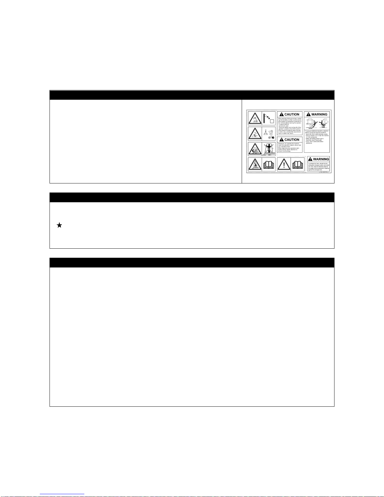
2. FOR SAFE USE OF MACHINE
This manual classifies the risks into the following three categories to present the details of the safety
labels in easy-to-understand manner.
This denotes that there is an imminent hazard which will cause serious
personal injury or death.
The method of hazard circumvention is stated.
This denotes that there is a hazard which can cause serious personal injury
or death.
The method of hazard circumvention is stated.
This denotes that there is a potential hazard which may cause minor or
moderate personal injury or serious damage to this machine.
The method of hazard circumvention is stated.
This manual also provides the following to indicate what must be observed for the sake of the machine
and what will be of help.
This denotes that failure to handle the machine properly may damage the
machine or shorten its life.
This denotes helpful information.
Not only procedures for operation, inspection, and maintenance of this machine described in this manual
but also safety precautions should pertain to the case where this machine is only used for specified tasks.
Every circumstance incidental to use of this machine is unforeseeable, and therefore, cautions given in
this manual and on this machine do not necessarily cover every safety-related issue.
Necessary safety actions should be taken under your responsibility if operation, inspection, and
maintenance in a situation that is not described in this manual are performed.
Even in the above case, never attempt the works and operations this manual prohibits you to do.
CAUTION
NOTES
1-4
3. MACHINE OVERVIEW
3.1 SPECIFIED OPERATIONS
This machine is to be used for operation listed below.
• Crane operation
• Pick & Carry operation
This machine is a mobile crane which consists of a crawler type carrier and an upper structure of a boom
equipped crane.
This self-propelled crane is capable of moving (traveling) in the worksite and lifting an object weighing
within the rated total load.
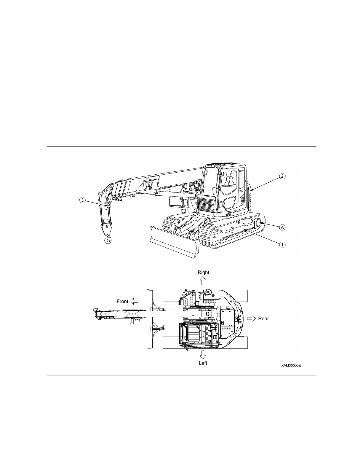
3.2 MACHINE CONFIGURATION
(1) Undercarriage
(2) Upper structure
(3) Safety device
In this manual, the terms front, rear, left and right refer to the travel
direction as viewed from the operator’s seat when the operator’s seat
is facing the front and the sprocket (a) is at the rear of the machine.
Boom slewing motion is determined with the machine viewed from
immediately above; slew clockwise denotes right-handed motion and
slew counterclockwise denotes left-handed motion.
EXTERNAL VIEW

1-5
This machine is composed of the units listed below.
[1] UNDERCARRIAGE
This is composed of a traveling gear and blade.
[2] UPPER STRUCTURE (CRANE)
This is composed of an engine, traveling operation unit, crane operation unit, telescoping system, derrick
system, slewing system, hook block, and winch system.
[3] SAFETY DEVICE
This is composed of the following parts and devices: Over hoist detector/automatic stop device,
three-winding stop alarm/automatic stop device, moment limiter (working envelope limited), slinging rope
detachment protector, hydraulic safety valve, telescoping cylinder hydraulic automatic locking device,
derricking cylinder hydraulic automatic locking device, alarm buzzer, machine tip-over alarm device, level,
working status lamp, crane and traveling control lever lock.
3.3 MACHINE FUNCTIONS
[1] UNDERCARRIAGE
• The carrier equips crawlers which enables this machine to enter into rough or soft terrains.
• Two-traveling lever operation enables not only direction changes among forward, backward, and
right/left but pivot turn and spin turn.
[2] UPPER STRUCTURE (CRANE)
• The upper structure allows continual 360 degree rotation.
• Thanks to extending/retracting, derricking up or down and/or swing operations of the boom, as well as
wind/un-wind operation of the winch, you can move the hoisted load to the designated location, subject
to the staying within the rated total road and working radius.

1-6
4. QUALIFICATION FOR OPERATION
• A high incidence of occupational accidents in crane operation has been reported.
Be aware that experienced engineers are also no exception.
• Warnings and precautions defined in this manual shall be observed for safety assurance
during operation of the machine.
4.1 QUALIFICATION FOR CRANE OPERATION
Only personnel that have obtained the required license or training stipulated by laws and regulations
applicable to the place of use are qualified to operate this machine.
Contact the relevant government office or our sales service agency for further information.
1-7
5. TERMINOLOGY
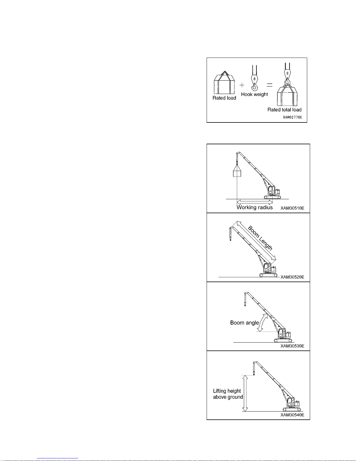
5.1 DEFINITIONS OF TERMS
[1] RATED TOTAL LOAD
This is the maximum load that can be applied according to a
boom length and angle. The load includes the mass (weight)
of hoisting accessories (hooks) and slinging ropes.
[2] RATED LOAD
This is a load derived by subtracting the mass (weight) of
hoisting accessories (hooks) and slinging ropes from the rated
total load, which is a withstand load for hoisting.
[3] WORKING RADIUS
This is a horizontal distance between the axis of slewing and
the hook center.
[4] BOOM LENGTH
This is a distance between the boom primary pin and the
sheave pin of the end boom.
[5] BOOM ANGLE
This is an angle which the boom forms with the horizon.
[6] LIFTING HEIGHT ABOVE GROUND
This is a vertical distance between the hook bottom and the
ground with the hook raised to the upper limit.

1-8
5.2 DIAGRAM OF WORKING RADIUS AND LIFTING HEIGHT
• The diagram of working radius and lifting height shows the relationships the working radius of
this machine, boom angle, and lifting height above the ground with no object hoisted. The
diagram has been made allowing for no deflection in the boom.
• The boom (4) in the diagram of working radius and lifting height represents a state that half of
the “ mark” passes boom (3).
1. Point A denotes a boom angle and point B denotes a lifting
height above ground in the figure at right.
The same working radius is applied to points A and B.
2. The “diagram of working radius and lifting height” shows the
relationships the working radius, boom angle, and lifting
height at no load, allowing for no deflection in the boom.
A deflection occurs in the boom when an object is hoisted,
which causes the working radius to increase slightly.
The rated total load decreases with an increase in the
working radius. Actual crane operation requires the planning
of work, allowing for sufficient tolerance of more than that
shown in the diagram.

1-9
5.3 RATED TOTAL LOAD CHART
• All the values provided in the rated total load chart are based on the assumption that the
machine is placed on a level and firm surface.
• The values in the rated total load chart are determined based on the working radius allowing
for deflection that is developed when load is applied to the boom.
• When extending boom (3) even if only slightly, crane operation should proceed to the extent of
performance of “Boom (3)”.
• When extending boom (4) even if only slightly, crane operation should proceed to the extent of
performance of “Boom (4)”.
• When half of the “ mark” passes boom (3), crane operation should proceed to the extent of
performance of “Boom (5)”.
• If the working radius exceeds that stated in the table even if only slightly, crane operation
should proceed with respect to the rated total load corresponding to the working radius in the
following table.
• The rated total load is a load including the mass of a hoisting accessory (hook: 90kg).
1-10
The rated total load chart provides the maximum loads that the crane is capable of hoisting objects in
parallel with the length of the boom. The loads are specified by working radius.
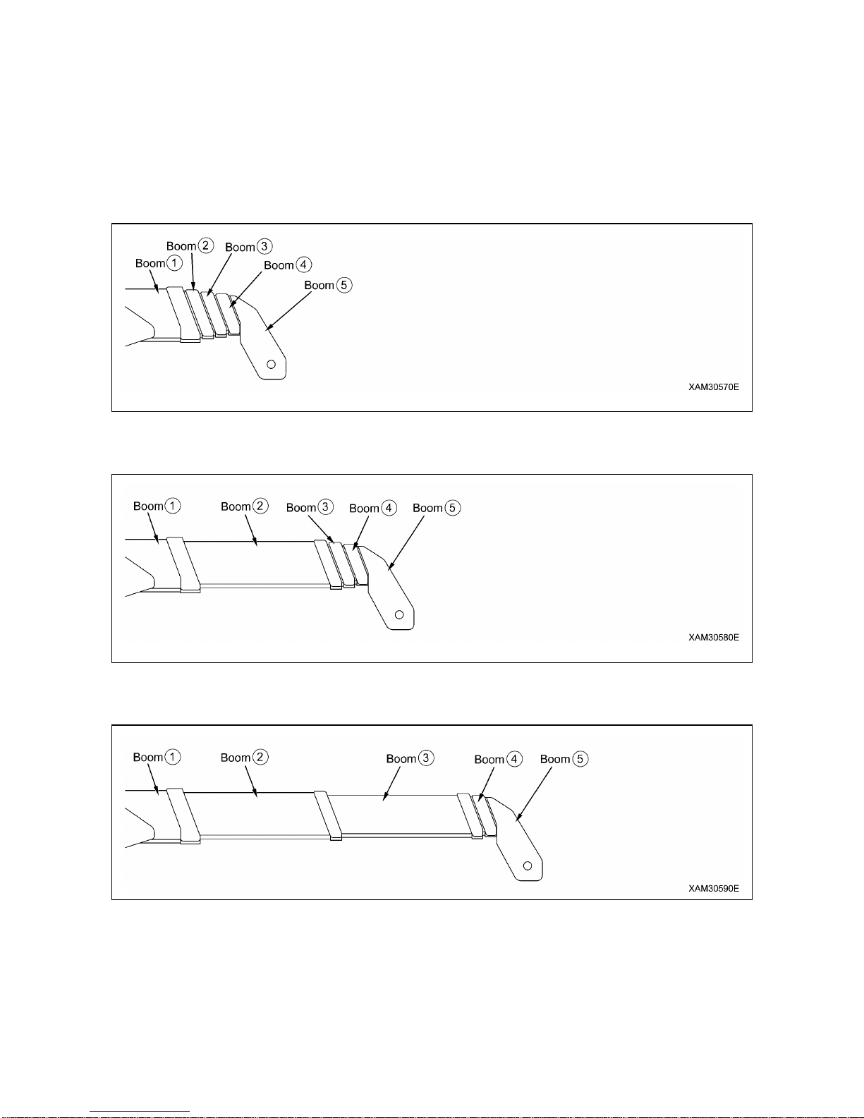
[1] BOOM LENGTH
The following figures illustrate the condition of the booms, “(1) 4.745m Boom”, “(2) 7.625m Boom”, “(3)
10.505m Boom”, “(4) 13.385m Boom”, and “(5) 16.265m Boom” in the preceding boxes in the rated total
load chart.
1. “(1) 4.745m Boom”: All the booms are retracted.
2. “(2) 7.625m Boom”: With booms (3), (4), and (5) retracted, boom (2) is fully extended.
Boom (2) is to apply to crane operation with boom (2) extended even if only slightly.
3. “(3) 10.505m Boom”: With booms (4) and (5) retracted, booms (2) and (3) are fully extended.
Boom (3) is to apply to crane operation with boom (3) extended even if only slightly.

1-11
4. “(4) 13.385m Boom”: With booms (2) and (3) fully extended, booms (4) and (5) are extended midway
(half of the “ mark” passes boom (3)).
Boom (4) is to apply to crane operation with booms (4) and (5) extended even if only slightly.
5. “(5) 16.265m Boom”: All the booms are fully extended.
Boom (5) is to apply to crane operation with half of the “ mark” on boom (4) passes boom (3).

1-12

2-1
SAFETY
1. BASIC PRECAUTIONS
2- 2
2. DRIVING RELATED PRECAUTIONS
2- 8
3. TRANSPORT PRECAUTIONS
2-25
4. TOWING PRECAUTIONS
2-26
5. MAINTENANCE PRECAUTIONS
2-27
6. SAFETY LABEL LOCATIONS
2-34
All the safety precautions defined in this manual should
always be read and observed.
Failure to follow the safety precautions can cause serious
personal injury or death.
2-2
1. BASIC PRECAUTIONS
Failure to operate or maintain this machine properly can lead to serious personal injury or death. Be sure
to read this manual and each safety label thoroughly before performing operation or maintenance of this
machine and observe the safety precautions.
1.1 PRECAUTIONS FOR BEFORE STARTING OPERATION
OBSERVE THE MANUAL AND SAFETY LABELS
• Read well and understand this manual as well as the safety labels
labeled on various part of this Machine. Attempt to drive/operate
without understanding fully may result in wrong operation that may
cause personal or equipment accidents.
• Fully understand the proper use and inspection/maintenance
procedures, and exercise safe works.
• Make sure this manual and the safety labels labeled on various part
of this Machine are legible all the time.
Whenever illegibility or loss occurs, order from us or our sales
service agency and put the safety label back to the original location.
DRIVING LICENSE
• Licenses or training certificates are necessary to drive this Machine.
Always obtain a license or training certificate before driving.
See “Introduction 4. Qualification for Operation” for details
• The drivers are requested to receive education and training in the handling methods and other
subjects from the applicable office, and obtain sufficient driving operation skills before work.
COMMIT TO SAFE OPERATION
•Obey the instructions and signs given by the manager and work supervisor, and observe safety first
during the work.
• Obey the crane work basics during work.
• Before starting driving or work, always carry out the inspections first.
• Do not work under bad weather for instance strong wind, thunder or mist.
• Do not drive under any condition when you are overtired, have drunk alcohol or after taking a somnific
drug.
• Obey all of the workplace rules, safety regulations and operation method sequences during driving
operations and inspection/maintenance.
• Pay attention to surrounding conditions and pedestrians all the time when driving or working.
Whenever pedestrian approaches unwarily, abort working once, and take a measure such as issuing a
warning.
• When driving, be mentally prepared for unexpected situations so that you can take the appropriate
action immediately.
• Do not attempt any use outside of the capabilities and purposes described in this manual under any
circumstance.
• Observe the designated rated total load and work range when driving.
• Do not attempt inattentive driving, harsh driving or awkward operation under any circumstance.
• Pull out the key when leaving operation seat.

2-3
1.2 PREPARATIONS OF SAFETY OPERATION
PROVIDE SAFETY DEVICES FOR SURE
• Check that all guards, covers, mirrors and rear view camera are attached properly. Repair immediately
if damaged.
• Understand how to use the safety devices correctly and use properly.
• Do not detach any safety device under any circumstance. Keep control to achieve proper operation at
all times.
• Improper use of safety devices can lead to serious bodily accidents.
• Do not rely solely on safety devices.
PREPARE FOR ABNORMALITY
• Carry out secure inspections and services, and be careful to
prevent accidents before they happen.
• Whenever you feel an abnormality of the Machine, abort working
immediately, ensure safety and report to the manager.
• Assign in advance who takes which solution to prevent secondary
accident.
• Do not drive the Machine when fuel or hydraulic oil is leaking from
the Machine. Report to the manager any abnormality, and fully
repair the fuel/hydraulic oil before use.
The fuel for this Machine is diesel oil. Be especially careful of any
fuel leak.
• Before leaving the Machine, lower the hoisted load to the ground,
stop the engine and pull out the engine key.
TEMPORARY STORAGE WHEN ABNORMALITY IS FOUND WITH MACHINE
In case the Machine is found with abnormality and is therefore stored
temporarily waiting for service, apply following measures to notify all
persons in the office that the use is prohibited due to failure.
• Indicate warning tags on the operation lever and other applicable
parts.
Write clearly the information such as abnormality contents, name
and contact of the storage manager, and the term of storage.
• Make sure the machine cannot move when parking by putting
blocks under the rubber tracks as pawls.
• Pull out the engine key and take it with you.
WEAR PROTECTIVE EQUIPMENT AND CLOTHES SUITABLE FOR WORK
• Always put on a helmet, safety shoes and safety belt.
• Select and make sure to put on necessary protective equipment
suitable for the relevant working condition.
• Do not wear loose garments or accessory items that may catch an
operation lever or protrusions and cause unexpected movement of
the Machine.

2-4
USE OF MACHINE THAT WAS RENTED OR PREVIOUSLY USED BY SOMEONE ELSE
Check the following subjects in writing before using any Machine that was rented or previously used by
someone else. In addition, check the inspection record table for the maintenance conditions such as the
periodic inspections.
(1) Crane capacity
(2) Crane maintenance condition
(3) Behavior and disadvantage unique to the crane
(4) Other subjects that require attention when driving
(a) operating condition of the brakes, clutches and others
(b) Presence/absence and lighting condition. Check of lighting and rotating lamps
(c) Operation condition of hook, winches, boom, outriggers and related
KEEP MACHINE CLEAN
• If inspection and maintenance is carried out when the machine is
still dirty with mud or oil, there is a hazard that you will slip and fall, or
that dirt or mud will get into your eyes. Always keep the machine
clean.
• If water gets into the electrical system, there is a hazard that it will
cause malfunctions or miss-operation. Do not use water or steam to
wash the electrical system (sensors, connectors).
KEEP OPERATOR’S COMPARTMENT CLEAN
• When entering operator’s compartment, always remove all mud and oil from the soles of your shoes. If
you operate the pedal with mud or oil affixed to your shoes, your foot may slip and this may cause a
serious accident.
• Do not leave parts or tools lying around the operator’s compartment.
• Do not stick suction pads to the window glass. Suction pads act as a lens and may cause fire.
• Never bring any dangerous objects such as flammable or explosive items into the operator’s
compartment.
• Do not use cellular telephones inside operator’s compartment when driving or operating the machine.
PROVISION OF FIRE EXTINGUISHER AND FIRST AID BOX
Always observe followings to prepare for injuries and fires.
• To prepare for fires, decide on the fire extinguisher storage location
and install one, fully read the attached label for its uses and be
prepared for fighting any emergencies.
• Decide the location to store the first aid box. In addition, inspect the
first aid box periodically and replenish the contents as necessary.
• Decide the measures to take upon an injury or fire accident.
• Decide how to contact the emergency address (for instance the
emergency physician, ambulance or fire department), and show the
contact address at designated position so any person can make the
contact.

2-5
1.3 PRECAUTIONS FOR FIRE PREVENTION
ACTION IF FIRE OCCURS
If a fire occurs, escape from the machine as follows.
• Turn starter switch OFF to stop engine.
• Use the handrails and steps to get off the machine.
FIRE PREVENTION AND EXPLOSION PREVENTION
• FIRE CAUSED BY FUEL, OIL, OR ANTIFREEZE, AND WINDOW
WASHER FLUID
Fuel, oil, antifreeze, and window washer fluid are particularly
flammable and can be hazardous. To prevent fire, always observe
the following:
• Do not smoke or use any flame near fuel oil, antifreeze, or window
washer fluid.
• Stop the engine before refueling.
• Do not leave the machine while adding fuel or oil.
• Tighten all fuel and oil caps securely.
• Do not spill fuel on overheated surfaces or on parts of the electrical
system.
• After adding fuel or oil, wipe up any spilled fuel or oil.
• Put greasy rags and other flammable materials into a safe
container to maintain safety at the work place.
• When washing parts with oil, use a non-flammable oil. Diesel oil
and gasoline may catch fire, so do not use them.
• Do not weld or use a cutting torch to cut any pipes or tubes that
contain flammable liquids.
• Use well-ventilated areas for adding or storing oil and fuel.
• Keep oil and fuel in the determined place and do not allow
unauthorized persons to enter.
• When carrying out grinding or welding work on the chassis, move
any flammable materials to a safe place before starting.
• FIRE CAUSED BY ACCUMULATION OF FLAMMABLE
MATERIAL.
Remove any dry leaves, chips, pieces of paper, dust, or any other
flammable materials accumulated or affixed around the engine,
exhaust manifold, muffler, or battery, or inside the under-covers.
• FIRE COMING FROM ELECTRIC WIRING
Short circuit in the electrical system can cause fire.
• Always keep electric wiring connections clean and tightened.
• Check the wiring every day for looseness or damage. Tighten any
loose connectors or wiring clamps. Repair or replace any damaged
wiring.
• FIRE COMING FROM HYDRAULIC LINE
Check that all the hose and tube clamps, guards, and cushions are
securely fixed in position. If they are loose, they may vibrate during
operation and rub against other parts. This may lead to damage to
the hoses, and cause high-pressure oil to spurt out, leading to fire
damage or serious injury.
• EXPLOSION CAUSED BY LIGHTING EQUIPMENT
• When checking fuel, oil, battery, electrolyte, window washer fluid,
or coolant, always use lighting with anti-explosion specifications. If
such lighting equipment is not used, there is danger of explosion
that may cause serious injury.
• When taking out the electrical power for the lighting from the
machine itself, follow the instructions in this manual.

2-6
1.4 PRECAUTIONS WHEN GETTING ON OR OFF
USE HANDRAILS AND STEPS WHEN GETTING ON OR OFF
To prevent personal injury caused by slipping or falling off the
machine, always do as follows.
•Use the handrails and steps marked by arrows in the diagram on the
right when getting on or off the machine.
• To ensure safety, always face the machine and maintain three-point
contact (both feet and one hand, or both hands and one foot) with
the handrails and steps (including the track shoe) to ensure that you
support yourself.
• Before getting on or off the machine, check the handrails and steps
(including the track shoe). If there is any oil, grease, or mud on the
handrails and steps (including the track shoe), wipe it off
immediately. Always keep these parts clean. Repair any damage
and tighten any loose bolts.
• Do not grip the control levers, or lock lever when getting on or off the
machine.
• Never climb on the engine hood or covers where there are no
non-slip pads.
• Do not get on or off the machine while holding tools in your hand.
• Never jump on or off the machine, Never jump on or off a moving
machine.
• If the machine starts to move when there is no operator on the
machine, do not jump on to the machine and try to stop it.
PRECAUTIONS WHEN LEAVING OR STANDING UP FROM OPERATOR’S SEAT
• Before standing up from operator’s seat (such as when opening or
closing the front window or roof window, or when removing or
installing the bottom window, or when adjusting the operator’s seat),
always store the crane completely, set lock lever (1) securely to the
LOCK position (L), then stop the engine. If you accidentally touch
the control levers or pedals when they are not locked, there is a
hazard that the machine may suddenly move and cause serious
injury or property damage.
• When leaving the machine, always store the crane completely, set
lock lever (1) securely to the LOCK position (L), then stop the
engine. Use the key to lock all the equipment. Always remove the
key, take it with you, and keep it in the specified place.
EMERGENCY EXIT OF THE OPERATOR'S CABIN
• In an emergency where the cabin door is blocked or does not open,
use the emergency hammer and smash the windowpane so that
you get out of the cabin through it.
• When you go through, remove fragments of the windowpane to
prevent injury from them. In addition, take care of your footpath to
avoid slipping on fragments of that.
2-7
1.5 OTHER PRECAUTIONS
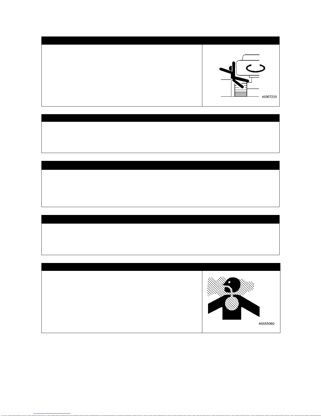
PRECAUTION NOT TO BE CAUGHT IN THE MACHINE
Around the upper structure and craning devices, movement of the
derricking cylinder and/or winch make the opening space vary. When
one becomes caught in such an opening, it may result serious
personal injury or death.
Always keep persons away from such rotating or telescoping part.
Especially, avoid putting oneself or your body into locations as below:
• Clearance between boom and upper structure
• Clearance between boom and derricking cylinder
• Clearance between winch drum and wire rope
• Clearance between each sheaves and wire rope
DO NOT MODIFY
Do not modify the Machine without our written consent under any circumstance. Especially, welding
work which can damage safety devices badly.
The modification raises a safety issue, so consult us or our sales service agency beforehand.
We cannot be held responsible for any bodily accident or failure caused by modification that was
performed without consulting us.
ATTACHMENT INSTALLATION
• When installing optional parts or attachments, there may be problems with safety or legal restrictions.
Therefore contact our sales service agency for advice.
• Any injuries, accidents, or product failures resulting from the use of unauthorized attachments or parts
will not be the responsibility of Maeda.
• When installing and using optional attachments, read the instruction manual for the attachment, and
the general information related to attachments in this manual.
CAB WINDOW GLASSES
• If a pane of the cab window is broken, stop the machine immediately and replace the broken pane with
new one.
• The ceiling window is made of organic glass (polycarbonate), and as such it is apt to break easily when
receiving damage on the surface, thereby deteriorating its protective characteristic. If there is a crack
or damage caused by a fallen rock, or when any sign of them is noticed, replace it with new window.
BEWARE OF EXHAUST GAS
When starting the engine or handling fuel/cleaning oil/paint indoors or
at a location with bad ventilation condition, prevent gas-poisoning risk
by improving the ventilation by opening the windows and exits.
If the ventilation is insufficient even after opening the windows and
exits, set up a ventilation fan.

2-8
2. DRIVING RELATED PRECAUTIONS
2.1 PRECAUTIONS FOR JOBSITE
SAFETY AT JOBSITE
Before starting operations, thoroughly check the area for any unusual conditions that could be
dangerous.
• When carrying out operations near combustible materials such as thatched roofs, dry leaves or dry
grass, there is a hazard of fire, so be careful when operating.
• Check the terrain and condition of the ground at the worksite, and determine the safest method of
operation. Do not operate where there is a hazard of landslides or falling rocks.
• Flatten the inclination of the working site as much as possible before starting work.
• When working over the roadway, enforce keep out by for instance placing guides or surrounding by
barriers, and ensure the safety of the traffic vehicles and pedestrians.
• Enforce keep out to prevent people from entering the working site and apply measures to prevent
people from approaching. Attempt to approach moving Machine may result in hard collision by contact
or pinching, and may result in serious bodily accidents and deaths.
• When travelling or operating in shallow water or on soft ground, check the sharpness and condition of
the bedrock, and the depth and speed of flow of the water before starting operations.
• Avoid traveling or operating your machine too close to the edge of cliffs, overhangs, and deep ditches.
The ground may be weak in such area. If the ground collapses under the weight or vibration of the
machine, there is a hazard that the machine may fall or tip over. Remember that the soil after heavy
rain or blasting or after earthquakes is weak in this area.
• When working on embankments or near excavated ditches, there is a hazard that weight and vibration
of the machine will cause the soil to collapse. Before starting operations, take steps to ensure that the
ground is safe and to prevent the machine from rolling over or falling.
ENSURE GOOD VISIBILITY
This machine is equipped with mirrors to improve the visibility, but even with mirrors, there are places,
which cannot be seen from the operator’s seat, so always be careful when operating.
When operating or traveling in places with poor visibility, if it is impossible to confirm the condition of the
job side or obstacle is in the area around the machine, there is danger that the machine may suffer
damage or the operator may suffer serious personal injury.
When operating or traveling in places with poor visibility, always observe the following items strictly.
• If the visibility cannot be sufficiently assured, position a flagman if necessary. The operator should pay
careful attention to the signs and follow the instruction of the flagman.
• The signals should be given only by one flagman
• When working in dark places, turn on the working lamps and front lamps of the machine, and if
necessary, set up additional lighting in the area.
• Stop operations if there is poor visibility, such as in fog, snow, rain, or sand storms.
• Check the mirror on the machine before starting operations every day. Clean off any dirt and adjust the
view to ensure good visibility.
• In area where it is impossible to confirm the area behind the machine and observation cameras have
been set up, clean off any dirt from the lens and make sure that the camera gives a clear view of the
rear. If a rear-view camera has been installed to show the area to the rear of the machine, clean off any
dirt from the lens and make that the camera gives a clear view of the rear. If there is any problem with
the camera and the rear view cannot be displayed, contact us or our sales service agency as soon as
possible and ask for repairs to be carried out.
SIGNALMAN’S SIGNAL AND SIGNS
• Set up signs to inform of road shoulders and soft ground. If the visibility is not good, position a
signalman if necessary. Operators should pay careful attention to the signs and follow the instructions
from the signalman.
• Only one signalman should give signals.
• Make sure that all workers understand the meaning of all signals and signs before starting work.

2-9
BEWARE OF ELECTRICAL CABLE ABOVE
• Do not let the Machine contact with electrical cables overhead.
High voltage cables may inflict electrical shock by just approaching.
• Persons who sling are likely to suffer electrical shocks.
Always observe followings to prevent accidents.
• If the boom or the wire ropes may contact an electrical cable in the
workplace, consult the electricity company and make sure that the
measures (measures for instance placement of a guard personnel
or application of wrap tubes and warning tags to the electrical
cable) stipulated by the related regulations are taken before
starting work.
• Put on rubber soled shoes and rubber gloves, and be careful that
the body parts unprotected by rubber or other insulation do not
contact the wire rope or the Machine frame.
• Place a guide and let him/her watch so that the boom, wire rope or
Machine frame does not go near the electrical cable too much.
Before doing so, decide the emergency signs and other
necessities.
• Ask the electricity company for the voltage in the electrical cables
in the working site.
• Ensure the offset distances (safe distance) shown in the following
table between the boom/Machine frame and electrical cables.
Voltage of
Electrical Cable
Minimum Safe
Distance
Low voltage
(Distribution line)
100・200V
2m
6,600V
2m
Special
(Transmission
line)
22,000V
3m
66,000V
4m
154,000V
5m
187,000V
6m
275,000V
7m
500,000V
11m

2-10
MEASURES WHEN CHARGE ACCIDENT OCCURS
When an electrical charge accident occurred, do not panic and stay calm, apply the solution in the
following sequence.
1. Report
Immediately report to the electricity company or related management company, and receive
instructions for the power transmission stop, emergency procedures and related.
2. Evacuation of related personnel from vicinity of Machine
Let the related personnel including the workers from vicinity of the Machine to prevent secondary
disasters.
Personnel who suffered electrical shock by holding a sling rope, guide rope or other conductor when
the Machine was charged should evacuate by his/her own effort.
Do not try to help such person. Otherwise, secondary electrical shock accident can occur.
3. Emergency procedure
Take the solution by following sequence in case of urgency where personnel received electrical shock
because the Machine was charged.
(1) If the Machine can be operated, immediately operate the Machine to move the Machine
constructions away from the contact and out of the range of the cause of the charge. Be careful
not to snip the distribution power cable.
(2) Evacuate the Machine completely away from the cause of the charge, make sure the Machine is
not charged, rescue the electrically shocked personnel and immediately carry to the hospital.
4. Measure after accident
After accident, do not reuse as is. Such attempt may cause unexpected accidents and enhances
failures. Ask us or our sales service agency for repair.
CAUTIONS WHEN WORKING WITH CRANE IN LOCATION WITH HIGH OUTPUT
MICROWAVE EMISSION
Working with crane near high output microwave emission equipment such as a radar or TV/radio
broadcast antenna causes the crane construction to be exposed to the microwave and generates
induced current, therefore is very dangerous. In addition, the mechatronics may become disturbed.
Establish grounding between the Machine frame and the ground when working in such location. In
addition, slingers are requested to wear rubber boots and rubber gloves since risk of electrical shock by
contacting parts such as the hook or wire exists.
BEWARE OF ASBESTOS DUST
Inhalation air containing asbestos may result in lung cancer. This
Machine does not use any asbestos, but asbestos may be contained
in the wall, ceiling or other part of construction within the work area of
this Machine. In addition, be careful of the followings when working
with a material that may be using asbestos.
• Put on designated dust free mask and/or other equipment as
necessary.
• Do not use compressed air for cleaning.
• Spray water when cleaning to prevent asbestos dusts from flying
into air.
• Always work at windward location when driving the Machine at a
site that may contain asbestos dusts.
• Enforce keep out to prevent people from entering the working site.
• Strictly observe the assigned rules related to the working site and
environmental standard.
2-11
2.2 PRECAUTIONS WHEN ENGINE STARTING
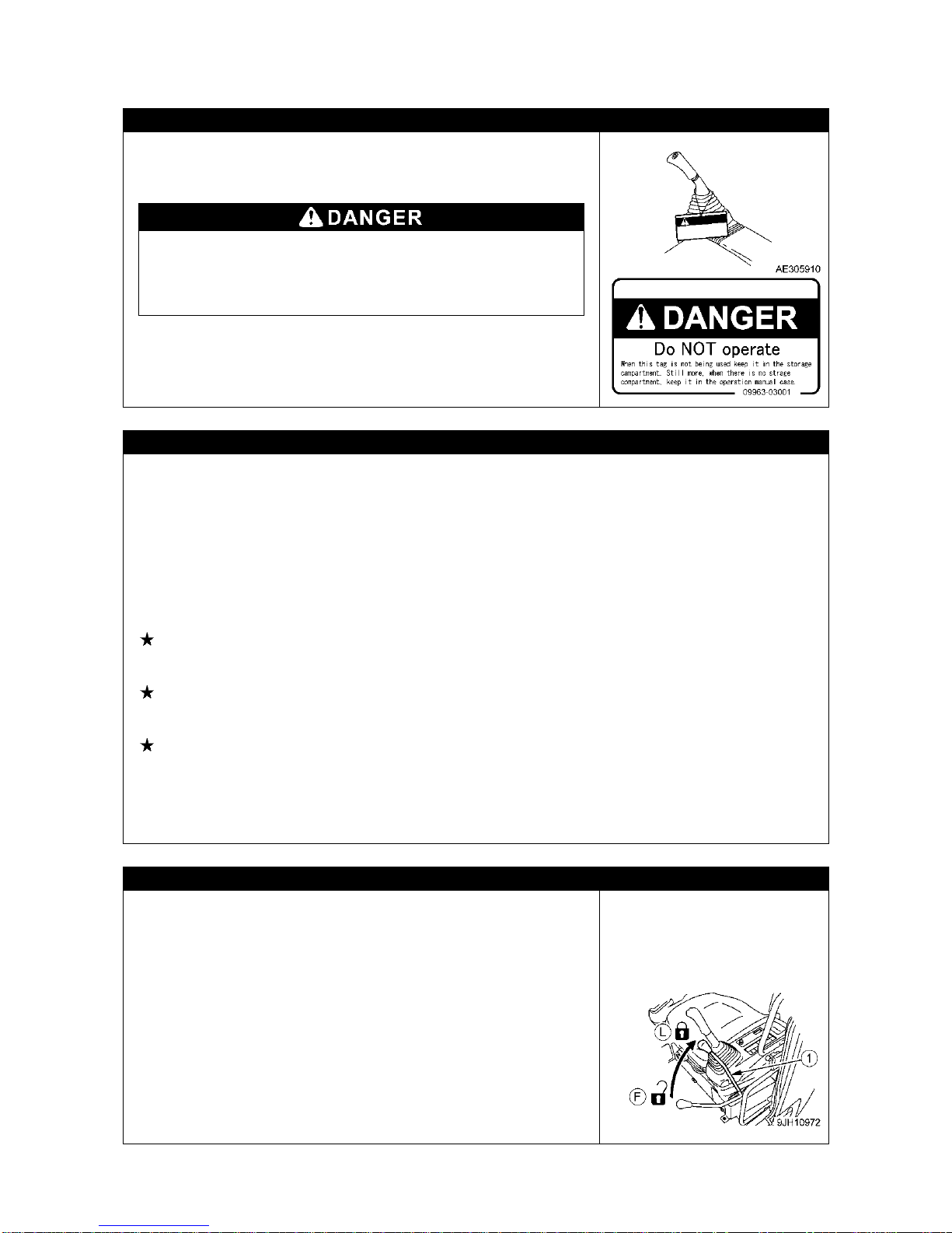
PRECAUTIONS FOR WARNING TAG
If there is a warning tag hanging from working equipment control
lever, do not start the engine or touch the levers.
Do NOT operate
When this tag is not being used, keep it in the storage
compartment. If there is no storage compartment, keep it in the
operation manual case.
INSPECTION BEFORE STARTING ENGINE
Check the instructions in "Operation 3.1 Check Before Operation" as well as followings, without starting
the engine and before starting work every day:
Omitting these inspections may result in serious bodily accidents.
• Do not fail to perform the check before operation.
• Remove all dirt from the surface of the window glass to ensure a good view.
• Remove all dirt from the surface of the lens of the working lamps, and check that they light up correctly.
• Check/refill engine coolant, fuel and the engine oil pan, and check for air cleaner clogging or electrical
circuit breakage.
• Adjust the operator’s seat to a position where it is easy to carry out operations, and check that there is
no damage or wear to the seat belt or mounting clamps.
See “Operation 3.1.2 [11] Adjusting Operator’s Seat” for details.
• Adjust the mirrors so that the rear of the machine, and winch drum can be seen clearly from the
operator’s seat.
See “Operation 3.1.2 [12] Adjusting Mirrors” for details.
• Check the monitor of the rear view camera and adjust the angle of the camera so that the proper view
is provided.
See “Operation 3.1.2 [14] Adjusting Angle of Rear View Camera” for details.
• Check pedals for piled up mad or alien substances which may disturb their movement, and remove
those, if any, to secure correct functions.
• Check the operation of the instruments and gauges, and check that the control levers are all at the
Neutral position.
Always repair if any result of the above is faulty.
CHECKS BEFORE STARTING ENGINE
• Make sure no person or object is within the boom swing radius area
before starting engine.
• Make sure no person is on or below the machine or around it, as
well as no person or object is within the boom swing radius area,
before starting engine.
• Do not allow anyone apart from the operator to ride on the machine.
• Start and operate the machine only while seated.
• Before starting engine, check that the control levers are all at the
Neutral position.
• Before starting engine, check that lock lever (1) is in LOCK position
(l).
• When starting the engine, sound the horn as a warning.
• Do not attempt to start the engine by short-circuiting the engine
starting circuit. Such an act may cause a serious bodily injury or fire.

2-12
CAUTIONS UNDER COLD WEATHER
• Remove snow from and defreeze the swing gear, boom and winch
related parts, and check the movements before work.
• Warm up enough. Attempting to operate the control levers and
pedals without enough warm-up causes the Machine to react dull,
and may result in unexpected accidents.
• If the battery fluid is frozen, do not charge battery or start the engine
using other power source. Such an act may cause the battery to
catch fire. Before charging or starting up using other power source,
defreeze the battery fluid and check that failures such as battery
fluid leak do not exist.
• After end of the work, wipe off and apply wraps if substances such
as condensation, snow or mud are stuck to the wire harness,
connector (1), switches, sensors or similar part.
If the infiltrated condensation and/or similar substances freeze, the
Machine may operate improperly upon the next use and cause
unexpected accidents.
CAUTIONS WHEN STARTING UP USING BOOSTER CABLE
Wrong booster cable connection method may result in fire, so always
observe the followings.
• When starting up the engine using a booster cable is attempted,
always arrange 2 persons, one in the cabin and another with the
battery.
• When starting using other Machine, be careful to prevent contact
between the normal Machine and broken Machine.
• Keep the starter switch key of both the normal Machine and the
broken Machine in OFF position when the booster cable is
connected.
• Do not connect to wrong side [connecting (+) to (-), (-) to (+)] when
connecting the booster cable.
• Start connecting from (+) terminal first, but start disconnecting from
(-) terminal (ground) first.
• Connect the ground to the (-) terminal of the battery of the broken
Machine when connecting the ground as the last procedure.
See “Operation 9.4.4 Starting Engine with Booster Cable” for
details.
• Avoid the contact between clips of the booster cable, and contact
between a clip and the Machine when disconnecting the booster
cable.

2-13
2.3 PRECAUTIONS WHEN STARTING TO MOVE MACHINE
CHECKS BEFORE OPERATION
Omitting the inspections after starting the engine results in delay to notice the Machine abnormalities,
and may result in bodily accidents and Machine damages.
Execute inspection in a wide location with no obstacle. In addition, be sure to prevent people from
approaching nearby the Machine.
• Check that the movement of the machine matches the display on the control pattern card. If it does not
match, replace it immediately with the correct control pattern card.
• Inspect the equipment operation conditions, Machine traveling conditions, winch winding up and down,
boom derricking, and crane operation conditions such as extension, retraction and swinging.
• Inspect the sound, vibration, heat and odor of the Machine, and check for instrument errors, air leaks,
oil leaks, fuel leaks, water leaks and other bad factors. Be extra careful with fuel leaks.
• Always repair broken part whenever an abnormality is found. Attempt to use without servicing may
result in unexpected bodily accidents and/or Machine failures.
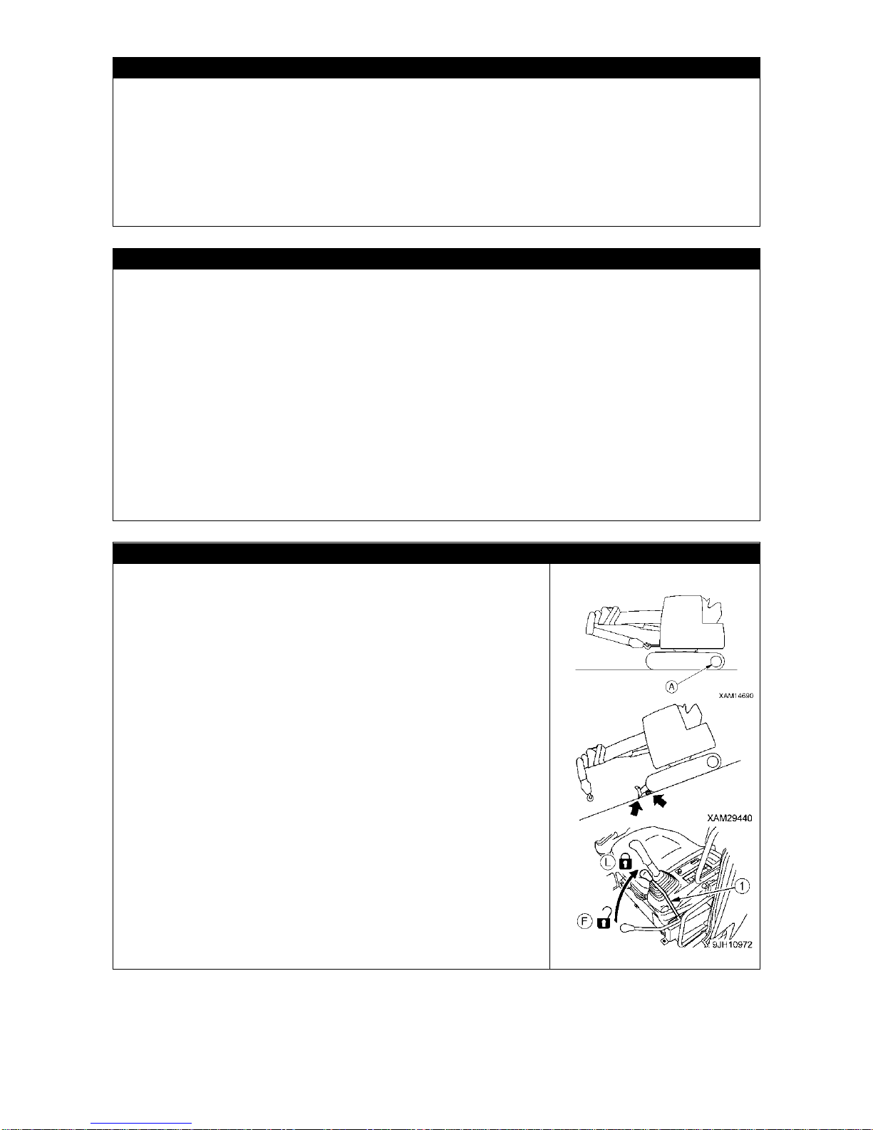
CAUTIONS WHEN MOVING FORWARD/BACKWARD OR CHANGING DIRECTION
To prevent serious injuries and death accidents, always execute the
followings before moving the Machine.
• Set the Machine to the traveling posture in the right diagram.
See “Operation 3.7 Machine Traveling Posture” for details.
Do not travel when the hook block is not contained.
• Before traveling, set the machine so that sprocket (A) is behind the
operator’s seat. If sprocket (A) is in front of the operator’s cab, the
machine will move in the opposite direction from the operation of
the levers (front and rear travel is reversed, left and right steering is
reversed). Be extremely careful when operating the machine in this
situation.
• Make the boom fully lowered and retracted.
• Fix the hook block to the containment position.
For a short distance travel, secure the hook block to the stowage
position below the boom tip. For longer travel, secure it to the
regular stowage wire rope in the front of the upper structure.
• Always lock the door and windows of the operator’s compartment in
position (open or close). On jobsites where there is a hazard of
flying objects or of objects entering the operator’s compartment,
check that the door and windows are securely closed.
• In an environment where anyone is around the machine, the
machine may smash or catch him/her, which results in death or
serious injury.
Before start traveling observe strictly as follows:
• Always operate the machine only while seated.
• Always fasten your seat belt.
• Before traveling, check again that there is no one in the
surrounding area, and that there are no obstacles.
• Before traveling, sound the horn to warn people in the area.
•After start traveling, check that the travel alarm correctly sounds.
• If there is an area to the rear of the machine which cannot be seen,
position a signal person. Take special care not to hit other
machines or people when turning or swinging the machine.
Though this machine is equipped with back mirrors and a rear view
camera, always arrange a person to guide safety traveling.

2-14
CAUTIONS WHEN TRAVELING
Always observe followings to prevent serious injuries and death
accidents when the Machine is traveling.
• Set the Machine to the traveling posture in the right diagram.
See “Operation 3.7 Machine Traveling Posture” for details.
• Do not attempt looking sideways or other dangerous act when
driving.
• Do not over speed, start moving sudden, stop sudden, swing
sudden or meander since such acts are dangerous.
• When traveling, always keep a safe distance from people,
structures, or other machines to avoid coming into contact with
them.
• When traveling on rough ground or steep slopes, If the machine is
equipped with auto-deceleration, always turn the auto-deceleration
switch OFF (cancel).
• Avoid traveling over obstacles when possible. If the machine has to
travel over an obstacle, keep at travel at low speed. Never travel
over obstacle which makes the machine tilt strongly to one side.
• When traveling on rough ground, travel at low speed and do not
operate the steering suddenly. There is a danger that the machine
may turn over. The machine may lose its balance, or may damage
the machine or structures in the area.
• When passing over bridges or structures, check first that the
structure is strong enough to support the weight of the machine.
When traveling on public roads, check first with the relevant
authorities and follow their instructions.
• When operating in tunnels, under bridges, under electric wires, or
other places where the height is limited, operate slowly and be
extremely careful not to let the crane hit anything.
BE CAREFUL WHEN TRAVELING OVER SLOPE
ALWAYS observe the following to prevent serious injuries and death
accidents when traveling over a slope for unavoidable reason.
• For traveling on a slope, always keep the correct traveling posture
with the hook block secured to the hook block stowage wire rope in
the front of the upper structure. When the hook block is temporary
stowed below the boom tip, it may become slack during traveling.
See “Operation 3.7 Machine Traveling Posture” for details.
• In a 10 degrees or more slope, use reverse traveling to climb it and
forward travel for descend. Always direct the machine front to the
downward of the slope. Where forward traveling to climb up and
reverse traveling for descend are used, it makes the machine
unstable and brings risks of overturning or drifting.
• Always travel straight up or down a slope. Traveling at an angle or
across the slope is extermely dangeropus.
• Do not turn on slopes or travel across slopes. Always go down to a
flat place to change the position of the machine, then travel on to the
slope again.
• When traveling downhill, lower engine speed, keep the travel lever
close to the neutral position, and travel at low speed.
• Travel on grass, fallen leaves, or wet steel plates with low speed.
Even with slight slopes there is a hazard that the machine may slip.
• If the engine stops when the machine is traveling on a slope, move
the control levers immediately to the neutral position and start the
engine again.
2-15
BE CAREFUL OF TIPPING ON UNSTABLE GROUND
Always observe followings to prevent serious injuries and death accidents when traveling over an
unstable ground for unavoidable reason.
• Do not enter soft ground area. The Machine is difficult to evacuate from such area.
• The ground near cliff, roadside and deep gully is unstable, so avoid going near such ground as much
as possible.
The Machine may tip or fall when the ground loosens due to mass and/or vibration of the Machine. Be
especially careful that the ground is likely loosened after rain, use of dynamite or earthquake.
• Avoid going near the earth fills or vicinity of dug gutter that are instable.
Crumbles caused by mass and/or vibration of the Machine may cause the Machine to tilt.
CAUTIONS WHEN SNOW COVERED OR FROZEN
Always observe the following to prevent serious injuries and death accidents when traveling over snow
covered ground or frozen road for unavoidable reason.
• The snow covered grounds and frozen roads cause slips even when the inclination is small, so
decrease the speed when traveling and avoid starting suddenly, stopping suddenly and swinging
suddenly. Uphill and downhill are especially likely to cause slips and thus dangerous.
• Ground of the frozen road becomes soft when the air temperature rises and causes the Machine travel
and other operations to be unstable. Be very careful.
• Under cold weather, check that the load to be hoisted is not frozen or stuck to the ground or other
substance. Attempting to hoist without knowing the load is frozen or stuck to the ground or other
substance is dangerous.
• Do not directly contact metal surface with your body part such as a finger or hand under cold weather.
Attempt to contact the metal surface of the Machine under harsh cold weather may cause the skin to
stick to the metal surface.
• Remove snow and/or ice laid on the Machine that causes the safety nameplates to be hard to read. Be
especially careful to securely remove those that are on the boom and thus may fall.
CAUTIONS WHEN PARKING
• Park the machine on firm, level ground.
• Select a place where there is no hazard of falling rocks or
landslides, or of flooding if the land is low.
• Set the Machine to the traveling posture in the right diagram.
• Make the boom fully lowered and retracted.
• Fix the hook block to the containment position.
For a short time parking, secure the hook block to the stowage
position below the boom tip. For longer parking, secure it to the
regular stowage wire rope in the front of the upper structure.
• Where it is un-avoidable to park the machine on a slope, observe
strictly as follows:
• Make the boom fully lowered and retracted.
• Fix the hook block to the containment position.
For a short time parking, secure the hook block to the stowage
position below the boom tip. For longer parking, secure it to the
regular stowage wire rope in the front of the upper structure.
• Set the front of the machine (blade) on the downhill side. Then dig
it into the ground.
• Put blocks under the tracks to prevent the machine from moving.
• When you leave the machine, observe strictly as follows:
• Set lock lever (1) to LOCK position (L), and then stop the engine.
• Always close the operator’s cab door, and use the key to lock all
the equipment in order to prevent any unauthorized person from
moving the machine. Always remove the key, take it with you, and
leave it in the specified place.

2-16
2.4 PRECAUTIONS WHEN WORKING WITH CRANE
INSPECTION BEFORE STARTING WORK
Check that the safety devices and crane operate properly.
• Operate each of the operation levers, pedals and switches under no load, and check that operations
take place without abnormality.
Repair immediately if any abnormality exists.
• Check that the safety devices such as the moment limiter, over hoist detector device and three-winding
stop alarm device activate properly.
PRECAUTIONS WHEN DECIDING THE CRANE OPERATION SITE
Always place the machine on the level and solid ground.
Crane operation is dangerous when the machine is placed in a site as below:
• Temporary asphalt pavements
• Thin concrete pavements
• Stone pavements
• Where the surface looks solid but the soil under it is soft, or the soil below pavement is washed by
water to become hollow.
• Soft grounds which may collapse or are near a shoulder of a road or an excavated hole.
• Slopes
PRECAUTIONS FOR CRANE OPERATION ON A SLOPE
Where a crane operation on a slope is un-avoidable, fill some soil (B)
to prepare a level and solid groundwork, first, and then place the
machine on it, so that overturning is prevented.
Unless this is done the crane is not placed level and attempting to
hoist will mean that the moment limiter (over-load detector) will not
work accurately, as well as un-foreseeable force to the machine
which may overturn or damage it.
FOLLOW INSTRUCTIONS AND SIGNS WHEN WORKING
• When working with the crane, appoint a work supervisor and mutual
signs beforehand, and follow the work supervisor and signs during
work.
• When working at a location where many parts are out of sight from
the driver, be especially careful to follow the instructions and signs
of the work supervisor and pay attention when driving.
• When working with the crane, the clearance between the boom and
the upper structure and also the gaps between the movable parts of
the derrick cylinder may catch body parts such as an arm or finger.
The driver is requested to make sure no one is within the working
radius of the crane before operating crane.
CAUTIONS HIGH TEMPERATURE OIL WHEN WORKING WITH CRANE
When hydraulic oil temperature exceeds 80 degrees, high pressure hoses and seals can be damaged
by heat, and it may cause burn by spouted oil.
If temperature of hydraulic oil becomes over 80 degrees, stop operation and wait until the oil cools
down.
Continuous hook raising / lowering operation at high working lifting height and a long time accelerated
operation are easier to raise oil temperature. Especially be careful for these operations.

2-17
CAUTIONS UNDER COLD WEATHER
• Remove snow from and defreeze the swing gear, boom and winch related parts, and check the
movements before work.
• Check the operation of winch brake.
• Warm up enough. Attempting to operate the operation levers, pedals and switches without enough
warm-up causes the Machine to react dull, and may result in unexpected accidents.
For details of warm up operation, see “Operation 3.4.1 Engine Warm Up”, “Operation 3.4.2
Hydraulic Equipment Warm Up”.
• Accumulation of snow within the working range of the crane can cause turnover of the unloaded load
or the workers around may trip over. Remove snow sufficiently before starting crane operation.
• If the load to be hoisted is stuck to the ground because it is covered with snow or frozen, do not force to
hoist the load. Thoroughly remove the snow or unfreeze before the crane operation.
• After end of the work, wipe off and apply wraps if substances such as condensation, snow or mud are
stuck to the wire harness, connector (1), switches, sensors or similar part.
If the infiltrated condensation and/or similar substance freeze, the Machine may operate improperly
upon the next use and cause unexpected accidents.

2-18
PAY ATTENTION TO WEATHER INFORMATION
• In case of thunderstorm, risk of lightning exists, so abort working with crane, immediately lower the
load and contain the boom.
• Exposing the hoisted load to wind causes the load to swing and causes the Machine to be unstable,
thus is dangerous. Immediately lower the load and contain the boom when the wind is causing the load
to swing.
• If the maximum instantaneous wind speed is 10 m/s or greater, abort working with crane, immediately
lower the load and contain the boom.
• Even when the maximum instantaneous wind speed is below 10 m/s, the bigger the hoisted load, the
higher the hoisted load position, and the longer the boom, the wind effect increases accordingly. Be
very careful during work.
• When the boom is extended full or nearly full, take notice of that the winch wire ropes and electrical
cable for signals are also effect by the wind. In addition, the wind speed may extremely increase when
it blows through the high-rise buildings. Thus, be very careful when working near high-rise buildings.
• When a load such as a steel plate that has a large area exposed to wind is being hoisted, the wind
arriving from front/rear/side of the boom may cause the Machine to trip or damage the boom. Be very
careful when working.
• In a condition where wind blows to the front face of the boom, the higher the boom is raised, the more
you may run a risk of overturning backward. Be very careful when working in such conditions.
• When an earthquake occurs, abort working and wait until the earthquake is over.
The following table indicates approximate relation between the wind speed and wind effect. The wind
speed mentioned in the weathercast is mean wind velocity (m/s) during 10 m at 10 m above the
ground.
Force
Wind Speed (m/s)
Effect On Land
0
Less than 0.3
Smoke rises vertically.
1
0.3 - below 1.6
Wind motion visible in smoke.
2
1.6 - below 3.4
Wind felt on exposed skin.
3
3.4 - below 5.5
Leaves and smaller twigs in constant motion.
4
5.5 - below 8.0
Dust and loose paper raised. Small branches begin to move.
5
8.0 - below 10.8
Smaller trees sway. Some foam and spray.
6
10.8 - below 13.9
Large branches in motion. Whistling heard in overhead wires.
Umbrella use becomes difficult.
7
13.9 - below 17.2
Whole trees in motion. Effort needed to walk against the wind.
8
17.2 - below 20.8
Twigs broken from trees. Progress impeded.
9
20.8 - below 24.5
Light structure damage. Slates blown off.
10
24.5 - below 28.5
Trees uprooted. Considerable structural damage.
11
28.5 - below 32.7
Widespread structural damage.

2-19
CAUTIONS WHEN WORKING WITH CRANE
• The stability of the crane is determined horizontally. Although the stability also increases diagonally,
work exceeding the rated load causes the breakage of the boom or machine. The moment limiter
(overload detector) must not be activated even in diagonal direction.
• Be sure to verify that the moment limiter emergency stop cancel switch is at OFF (auto) position before
operating the crane. Do not attempt the crane operation when the moment limiter emergency stop
cancel switch is at ON (cancel) position. The moment limiter emergency stop cancel switch is
permitted to be at ON (cancel) position only during the inspection or maintenance works.
• Pay attention to indication and warning on the moment limiter while working.
• Attempt to work beyond the capacity of the Machine may cause serious accidents and failures caused
by for instance tripping or fluctuation. Observe the rated total load chart when working with the crane.
• Be slow when operating the crane.
Sudden lever or accelerator operations may cause risks such as swinging or falling of the load and
collision with the surroundings. Be especially careful to be slow during the swing operations.
• Determine a work supervisor for crane operation and always follow the instructions of the supervisor.
Follow the instructions of the supervisor for work methods and procedures.
Determine how to give signs and follow these signs.
• A long load is instable when hoisted and thus, dangerous. Attach a rope to the both ends of the load to
make the load stable.
• Do not let people approach the work radius or stand below the load, since risks such as fall of the load
and contact with the load exist. Such attempt may result in serious bodily accidents. Also, during the
work, consider the fact that the working radius increases when the load is hoisted and the boom is
deflected thus.
• Work that goes beyond the machine performance will cause accidents and failures. Particularly, the
crane operation must be performed based on the rated total load chart.
• Be careful to prevent the wire rope and/or hoisted load from contacting an obstacle such as a tree or
steel when hoisting a load.
If caught by an obstacle, do not forcibly wind up the hoist load, but untangle the caught part before
winding up.
• Do not pull laterally, pull toward you or hoist diagonally. Such attempt may cause the crane to tip or
suffer damage.
• Attempt to work with the crane when the view is bad due to location or weather is dangerous.
Ensure brightness by posting a work lamp or other illumination facility in dark places.
When the view is bad because of bad weather (rain, fog, and snow), abort working and wait until the
weather recovers.
• Do not use for purpose, for instance raising a person using a crane, other than the true purpose.
• If the over-winding detector alarm buzzer is heard, immediately leave your hand from the winch lever.
The hook block winding stops. Then, operate the winch lever to Down (push forward) to wind down the
hook block. In addition, the hook block is wound up when the boom is extended, so be sure to allow
extra clearance between the boom and the hook block during work.
• When the boom extends, the hook block is wound up.
Operate the winch lever to Down (push forward) to wind down the hook block while you extend the
boom.
• Whenever an overload occurs during work, lower the load by winding down the winch by setting the
winch lever to Down (push forward).
Do not raise or lower the boom acutely. Such attempt may cause serious accidents by tipping.
• The volume of the hydraulic oil in each of the cylinders changes depending on the temperature.
By leaving idle with a load being hoisted, as the time passes by the oil temperature drops and the
hydraulic oil volume decreases, and changes such as the boom derrick angle decrease and boom
length decrease may occur.
In that case, execute boom derricking operations and boom extension operations appropriately to
correct.
• Do not leave the driving operation position when a load is hoisted.
Lower the load and place lock lever to LOCK position before leaving the Machine.
• Keep the hook block wound up when not in use.
Otherwise, person near the load may collide the hook block without load.
• Operator must not leave operation seat during operation.
• The work that hoists an attachment that generates some vibration such as VIBROs is forbidden. The
vibration of the attachment may break the winch, etc.

2-20
CAUTIONS WHEN HANDLING MOMENT LIMITER
• Use/store the moment limiter under the following ranges of ambient temperature.
Temperature of use: -10 to 50 degrees C Storage temperature: -30 to 70 °C
• Avoid direct sunlight so that the temperature of the moment limiter body does not exceed the above
range.
• Avoid locations with strong acid or alkaline atmosphere as much as possible. Otherwise, unexpected
failures may occur.
• Do not apply impact to the moment limiter body for instance by colliding with an object.
Such attempt may damage the case and may result in failures and improper operations.
• Do not push the panel sheet of the moment limiter body by a force more than necessary or push with
sharp object such as a tip of a screwdriver. Such act may damage the panel sheet and may result in
failures and improper operations.
• Do not remove the case cover or panel sheet from, or disassemble the moment limiter body. Such act
may damage case and/or panel sheet and may result in failures and improper operations.
CAUTIONS WHEN SETTING UP MOMENT LIMITER
• The moment limiter calculates the moments assuming the Machine is level.
If you work with the crane when the Machine is not level, warnings and alarms are not issued even
when the rated total load is near. Always use the level to ensure that the machine is not at an angle.
• Before using the moment limiter, check that the boom angle display, boom length display and real load
display are displayed correctly following the crane movements. Attempt to use without correct display
results in failure to obtain correct measurement result and may result in serious bodily accidents
caused by reasons such as a tipping over and/or breakage of the machine.
• Always make sure the fall mode setting of the moment limiter matches with the wire fall of the crane.
Attempt to use unmatched wire falls may results in failure to obtain correct measurement and may
result in serious accidents caused by reasons such as a breakage of wire rope.
• Do not carelessly change the setting when measuring with the moment limiter. Such attempt results in
failure to obtain correct measurement result and may result in serious bodily accidents caused by
reasons such as a tipping over and/or breakage of the machine.
CAUTIONS WHEN SLINGING
• Check the following before hoisting a load.
Attempt to hoist the load without checking may result in serious bodily accidents by a drop of the load
or tipping of the crane.
• Observe the values in the rated total load chart.
• Hoist from the center of gravity of the load.
• Check that the wire ropes of the hook block are perpendicular to the ground.
• When the load leaves the ground, stop winding up the load once and check whether the load is
stable.
• Before hoisting a load, always check whether the sling wire rope "retainer device" of the hook block is
hanging securely If not the wire rope may leave the hook block and cause the load to fall and results in
a serious accident.
• Larger sling rope angle when hoisting the load increases force to the sling rope even when the load
weight is unchanged, thus may cause the sling rope to snap off. Be careful when slinging in order to
prevent excessive force to the sling rope.
• Do not hoist more than 1 load at a time.
This could cause the hoist bracket to hit and damage the other hoisted load, the loads may move and
loose balance and cause tipping, or some other cause of a serious accident.
Do not hoist more than one load even if the total is within the rated total load.
• Hoisting of lengthy load may cause the load to lose balance and is dangerous.
In case of lengthy such load, hoist vertically by using a cramp, or achieve balance of the hoisted load
by applying a rope to both ends of the load.

2-21
CAUTIONS WHEN HANDLING WIRE ROPE
• The wire rope wears down as the time passes, so inspect every
time before work, and replace immediately if at or beyond the
replacement standard.
At the same time, inspect the sheave at the tip of the boom and the
sheave of the hook block. Damaged sheaves accelerate the
damage of the wire ropes.
• Use the wire ropes specified by us.
• Wire rope breakage causing protruding wires may injure your
hands. Always put on leather gloves when handling the wire rope.
• Handling worn and damaged wire may cause injure by wire splinter.
• Do not use any wire rope of which any of the followings apply.
• 10% or more of the wires (except the filler wires) in one twist of the
wire rope are snapped off.
• The wire rope diameter wear is beyond 7% of the nominal
diameter.
• Is kinked.
• Is excessively deformed or corroded.
• Affected by heat or sparks.

2-22
CAUTIONS WHEN OPERATING WINCH
• Select the hook appropriate for the load weight and right number of
wire rope falls.
For details, see “Operation 5. Handling Wire Rope”.
• Do not let persons enter below the hoisted load.
• When hoisting a load, always stop once at the "takeoff" position
where the hoisted load leaves the ground. Check subjects such as
load stability and load force, then hoist up the load.
• Do not pull laterally, towards you or hoist diagonally. Such attempt
may cause the crane to tip or suffer damage.
• Over-winding of the hook block may result in collision with the
boom, snapping the wire ropes and causes the hook block and load
to fall and cause serious accidents. Be fully careful to prevent
over-winding the hook block.
• Be careful to prevent the wire rope and/or hoisted load from
contacting an obstacle such as a tree or steel when hoisting a load.
If caught by an obstacle, do not forcibly wind up the hoist load, but
untangle the caught part before winding up.
• Do not use the winch drum wire rope in random condition. If
random, not only the wire rope suffers damage and shortens the
lifetime, but the wire rope may snap and causes serious accidents.
Observe following precautions to avoid wire rope from becoming
random.
• Do not let the hook block hit the ground.
• Before leaving the hook block lowered for a long time, for instance
when working with underground, leave at least three loops of wire
rope in the winch drum.
• Release the accelerator pedal to decrease the engine speed, and
slowly return the right working control lever to decelerate from
high-speed hoisting. Returning the right working control lever
quickly at high speed will result in a rapid deceleration shock in the
hook, popping the hook and leading to irregular winding.
• Hoisting/Lowering in high-speed mode should be used to
hoist/lower the hook alone. Hoisting/Lowering the hung load in
high-speed mode can break boom, frame or cause serious
accidents in which the machine turns over.
• If the wire rope is twisted and causes the hook block to turn, fully
eliminate the twist before work.
See “Operation 4.2 What to do with Twisted Winch Wire Rope” for
details.

2-23
CAUTIONS WHEN OPERATING BOOM
• Be as slow as possible when operating the boom operation lever.
Especially avoid sudden lever operations when the load is hoisted,
which may cause the load to swing and give large impact to the
Machine, and thus may damage the crane or trip the Machine.
• When the boom is lowered, the working radius increases, and the
rated total load that can be hoisted decreases. When working while
raising/lowering the boom, pay extra attention so that the mass
(weight) of the load at the time the boom is most lowered does not
cause overloading.
• Attempts to pull the load laterally or pull to bring forth the load by
raising/lowering and/or extracting/retracting operation of the boom
are prohibited. Do not attempt under any circumstance.
• Be aware of the hook block windup condition and exercise caution
when extending or retracting the boom.
• When the boom is extended, the working radius increases, and the
rated total load that can be hoisted decreases. When working with
extending/retracting the boom, pay extra attention so that the mass
(weight) of the load at the time the boom is most lowered does not
cause overloading.
CAUTIONS DURING SWING OPERATION
• Check the safety in the vicinity and blow the horn before swinging.
• Be as slow as possible when operating the swing lever. Make sure
to start smoothly, swing slow, and stop gently.
Especially avoid sudden lever operations when the load is hoisted,
which may cause the load to swing and cause the Machine to lose
balance, and thus may damage the crane or tip the Machine.
• Attempts to pull to bring forth the load or let the load stand up by
swinging operation are prohibited. Do not attempt under any
circumstance.
• Be careful to prevent the wire rope and/or hoisted load from
contacting an obstacle such as a tree or steel when hoisting a load
or when swinging.
If caught by an obstacle, do not forcibly wind up the hoist load, but
untangle the caught part before winding up.
COOPERATION HOISTING IS PROHIBITED AS THE RULE
Tandem hoisting, that is to use more than one crane to hoist a load, is prohibited.
Tandem hoisting work is a highly hazardous work that may cause for instance a tip of the Machine due
to uneven center of gravity, fall of the hoisted load or boom damage.
If the need to work so exists for unavoidable reason, establish a work scheme by responsibility of the
user, discuss fully, let the worker fully acknowledge the work method and procedures, then work
carefully under the direct leadership of the work supervisor.
And, observe the following cautions as well.
• Use the cranes of same model.
• Choose the Machine model that can handle sufficiently larger load than the load to be hoisted.
• Make sure only one person gives signs.
• Limit the crane operations to single operations as the rule, and do not attempt any swing operation.
• Appoint one responsible slinger who is most experienced.

2-24
WORKING AT THE SITE WITH UNDERGROUND LIFTING
• Leave at least three loops of wire rope in the winch drum when winding down the wire rope in case of
underground work or similar occasion. This Machine is equipped with three-winding stop alarm /
automatic stop device as the safety device, but even then be very careful to prevent this safety device
from activating.
• Make sure signs are communicated fully.
• Be especially careful with the crane operations.
SAFETY RRECAUTIONS FOR PICK & CARRY OPERATION
Pick and carry operation is a very unstable and dangerous practice; it is prohibited, in genreal.
Where such an operation is un-avoidable, strictly observe followings. Failure to observe precautions
may result in death or serious injury.
• Observe the precautions specified in the operation manual:
Refer to "Operation 3.25.1 Safety Precautions for Pick and Carry Operation".
• Always keep the correct posture as specified in the operation manual:
Refer to "Operation 3.25.2 Posture for Pick and Carry Operation".
• The hoisted load should be within a safe load range and kept in a height near the ground.
• Arrange a person to guide the machine traveling.
• Remove all the obstacles in the pick and carry path and keep out all the persons.
• Hoisting in the boom configuration exceeding the rated length is prohibited.
• The rated total load is applicable only to the optimum condition. Limit the load to a safety level based
on the particular condition.
• To prevent the hoisted load from swinging in a pick and carry operation, keep the engine in low idling
(low speed rotation) and set the travel speed selector switch to the "Low" position. Avoide operations
such as sudden start and stop, or changing the travel speed to "High" position.
• During a pick and carry operation, never attempt shifting to the travel speed selector switch to the
"High" position, swinging the upper structure and/or other crane operations.

2-25
3. TRANSPORT PRECAUTIONS
CAUTIONS DURING TRANSPORT
When transporting the machine on a trailer, do as follows.
• The weight, transportation height, and overall length of the machine differ accroding to the crane.
• When passing over bridges or structure on private land, check first that the structure is strong enough
to support the weight of the machine.
• When traveling on public roads, check first with the relevant authorities and follow their instructions.
• For details of the transportation procedure, see “Operation 6. Transportation”.
CAUTIONS WHEN LOADING OR UNLOADING
When loading or unloading the machine, mistaken operation may
bring the hazard of the machine tipping over or falling, so particular
care is necessary. Always do as follows.
• Select a location that is level and has firm road surface when
loading or unloading the Machine. In addition, keep enough
distance from the roadside.
• Use the ramps under 15 degrees or smaller angle. In addition,
decide the clearance between ramps to meet the center of the
tracks.
• Use the ramps that have fully strong width, length and thickness,
and that enable safe loading/unloading. Reinforce with blocks or
other substances if the ramps deflect much.
• Remove the mud and other substances from the footing to prevent
the Machine from skidding over the ramps. Remove the substances
stuck the ramps such as grease, oil or ice, and keep clean.
Be especially careful in the rainy days where slips easily occur.
• Always turn the auto-deceleration switch OFF (cancel).
If the auto-deceleration switch is left ON, the machine may suddenly
move.
• When loading or unloading the machine, always keep it in a
traveling posture and fix the hook block by the stowage wire rope.
See “Operation 3.7 Machine Travel Posture” for details.
• When loading or unloading, set the engine rotation to low idling (low
speed rotation) and operate slowly by low speed travels.
• Always move backward when loading the Machine. Moving forward
may cause a trip.
• When on the ramps, do not operate any lever except for the travel
lever.
• Never correct your steering on the ramps. If necessary, drive off the
ramps, correct the direction, and then enter the ramps again.
• The center of gravity of the machine will change suddenly at the
point between the ramps and the truck or trailer, and there is danger
of the machine losing its balance. Travel slowly over this point.
• When loading or unloading to an embankment or platform, make
sure that it has suitable width, strength, and grade.
• When the machine is required to turn its direction on the carrier,
keep it in a traveling posture and operate slowly, as the base is
unstable.
• Always lock the door after loading machine. If this is not done, the
door may suddenly open during transportation.
• After loading the machine, apply the wood blocks so that the
machine does not move, and securely fix with wire ropes or other
means.
See “Operation 6.1 Loading/unloading” for details.
See “Operation 6.3 Cautions in Loading Machine” for details.

2-26
4. TOWING PRECAUTIONS
SAFETY RULES FOR TOWING
Serious injury or death could result if a disabled machine is towed
incorrectly or if there is a mistake in the selection or inspection of the
wire rope.
For details of towing, see “Operation 9.3 Lightweight Towing
Hook”.
• Always wear leather gloves when handling wire rope.
• During the towing operation, never stand between the towing
objects and the machine being towed.
• Never tow a machine on a slope.
• Never use a wire rope which has cut strands (A), reduced diameter
(C) or kinks (B). There is danger that the rope may break during the
towing operation.

2-27
5. MAINTENANCE PRECAUTIONS
5.1 PRECAUTIONS BEFORE MAINTENANCE
FAILURE REPORT
Execution of a maintenance not described in our manual may cause unexpected failures.
Ask us or our sales service agency for repair.
PRECAUTIONS FOR WARNING TAG
• Always attach the “Do NOT operate” warning tag to the work
equipment control lever in the operator’s cab to alert others that you
are performing service or maintenance on the machine. Attach
additional warning tags around the machine if necessary.
Warning tag Part No. 09963- 03001
Keep this warning tag in the tool box while it is not used. If there is
no tool box, keep the tag in the operation manual pocket.
• If others start the engine, or touch or operate the work equipment
control lever while you are performing service or maintenance, you
could suffer serious injury or property damage.
Do NOT operate
When this tag is not being used, keep it in the storage
compartment. When there is no storage compartment; keep it in
the operation manual case.
KEEP WORK PLACE CLEAN AND TIDY
• Do not leave hammers or other tools lying around in the work place. Wipe up all grease, oil, or other
substances that will cause you to slip. Always keep the work place clean and tidy to enable you to carry
out operation safety.
If the work place is not kept clean and tidy, there is the danger that you will trip, slip, or fall over and
injure yourself.
• When cleaning the ceiling window which is made of organic glass (polycarbonate), use tap water and
avoid use of organic solvents for cleaning. An organic solvent like benzene, toluene or methanol can
invite a chemical reaction like dissolution and decomposition on the window glass, deteriorating
polycarbonate in use.
SELECT A PLACE
• Stop the machine on firm, level ground.
• Select a place where there is no hazard of falling rocks or landsides, or flooding if the land is low.
PERSONNEL
Only authorized personnel can service and repair the machine. Do not allow unauthorized personnel
into the area. If necessary, employ an observer.
FOLLOW SUPERVISOR INSTRUCTION DURING TEAMWORK
Appoint a person who supervises the work and follow his/her instructions in case of Machine repair or
installing/uninstalling a work device.
Unexpected accidents due to misunderstood communication between workers may occur during
teamwork.

2-28
STOP ENGINE BEFORE CARRYING OUT MAINTENANCE
• Stop the machine on firm, level ground. Store the crane, and then
stop the engine.
• Turn the starter switch to the ON position. Operate the work
equipment control lever back and forth. Left and right at the full
stroke 2 to 3 times to eliminate the remaining internal pressure in the
hydraulic circuit, and then push up lock lever (1) to the LOCK
position (L) and turn starter switch to the OFF position.
• Check that the battery relay is off and main power is not conducted.
Wait for approx. one minute after turning off the engine starter
switch key and press the horn switch. If the horn does not sound,
it is not activated.
• Set the Disconnect Switch by the battery to " " position to cut the
power line, to prevent the engine from un-expected starting during
maintenance.
• Put blocks under the track to prevent the machine from moving.
TWO WORKERS FOR MAINTENANCE WHEN ENGINE IS RUNNING
To prevent injury, do not carry out maintenance with the engine
running. If maintenance must be carried out with the engine running,
carry out the operation with at least two workers and do as follows.
• One worker must always sit in the operator’s seat and be ready to
stop the engine at any time. All works must maintain contact with
the other workers.
• When carrying out operations near the fan, fan belt, winch drum, or
other rotating parts, there is a hazard of being caught in the parts,
so be careful not come close.
• Never drop or insert tools or other objects into the fan, or fan belt or
winch drum, or other rotating parts. Parts may break or be sent
flying.
• Do not touch any control levers or pedals. If any control levers or
pedals must be operated, always give a signal to the other workers
to warn them to move to a safe place.
• Release the pressure remaining in the hydraulic system and
operate the lock lever (1) to "Lock" position (L).
Refer to "Maintenance 12. Releasing the Internal Pressure from
the Hydraulic System".
• Do not touch any control levers or pedals. If any control levers or
pedals must be operated, always give a signal to the other workers
to warn them to move to a safe place.

2-29
USE APPROPRIATE TOOLS
Use only tools suited to the task and be sure to use tools correctly.
Using damaged, low quality, faulty, makeshift tools improper use of
the tools could cause serious personal injury.
PRECAUTIONS FOR ELEVATED WORK
For elevated work, prepare an appropriate elevated work platform with steps.
CAUTION WHEN WORKING UNDER THE MACHINE NAD CRANE
• Hoists or jacks used to lift the machine up must be capable to carry
on the weight of the component and be in a good condition, as well.
In addition, avoid using a hydraulic jack to lift up the damaged, bent
or twisted part of the machine. Also, the wire rope for hoisting should
be the one without any wire breakage, decreasing in the diameter
and/or kink. Avoid using bent or damaged hooks.
•If it necessary to go under the crane or the machine to carry out
service and maintenance, support the crane and machine securely
with blocks and stands strong enough to support the weight of the
crane and machine.
• Avoid using concrete blocks to support the machine. Concrete
blocks easily crush even in small loads.
CLEAN BEFORE INSPECTION OR MAINTAIN
• Before starting an inspection or maintenance, clean the Machine
and prevent rubbish from entering the Machine and make sure the
safety will be ensured during maintenance.
• Attempt to inspect or maintain with the maintenance Machine still
dirty not only lessens chance of locating faulty part, but may cause
rubbish or mud entering your eye, or slipping and tripping resulting
in injury.
• Always observe followings when washing the vehicle.
• Use anti-slip shoes to prevent slips and trips caused by wet
foothold.
• Put on protective equipment when using a high pressure steam car
wash. Avoid the accidents that the contact with high pressure
water causes such as skin laceration or mud or other substances
flying into eye.
• Do not directly spray water onto electrical system (sensors,
connector (1), receiving box and related). Entrance of water into
the electrical system causes faulty operations and may trigger
improper operations, thus is dangerous.
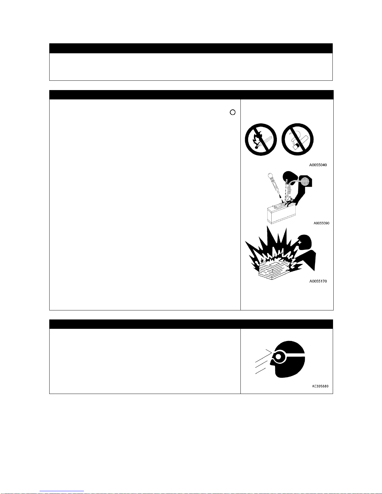
2-30
5.2 PRECAUTIONS DURING MAINTENANCE
CAUTIONS DURING WELDING REPAIR
Welding operation must always be carried out by a qualified welder and in a place equipped with proper
equipment. There is a hazard of gas, fire, or electrocution when carrying out welding, so never allow any
unqualified personnel to carry out welding.
BATTERY HANDLING CAUTIONS
To check or handle the battery, turn the starter switch to the OFF
(cut) position and set the disconnect switch by the battery to " "
position to cut the power line, to prevent the engine from un-expected
starting during maintenance.
The battery fluid includes diluted sulfuric acid, and generates
hydrogen gas, and causes bodily accidents and fires if handled
improperly, so always observe the followings.
• Do not let a cigarette or any fire source approach the battery.
• Always put on protective glasses and rubber gloves before handling
the battery.
• If the battery fluid contacted clothing or skin, immediately wash
away by huge quantity of water.
• If the battery fluid entered an eye, wash immediately with water and
see the doctor as soon as possible.
• If you have swallowed the battery fluid by mishap, immediately drink
huge quantity of water, milk, raw egg or vegetable oil, and see the
doctor as soon as possible.
• Wipe with a wet clean cloth when cleaning the battery upper surface
or related part. Do not use organic solvent or detergent, for instance
gasoline or paint thinner.
• Tighten the battery cap fully.
• If the battery fluid is frozen, do not charge battery or start the engine
using other power source. Such act may cause the battery to catch
fire.
• Before charging or starting up using other power source, defreeze
the battery fluid and check that failures such as battery fluid leak do
not exist.
• Always detach the battery from the Machine frame before charging
the battery.
BEWARE OF CHIPS WHEN WORKING WITH HAMMER
Whilst working with a hammer, keep protective equipment such as
protective glasses and a helmet on, and insert a copper bar or similar
object between the hammer and the target when hitting.
Giving impact to a hard metal part such as a pin or a bearing may
cause the broken chip to enter eye and inflict injury.

2-31
CAUTIONS WHEN COOLANT TEMPERATURE IS HIGH
To prevent burns from hot water or steam spurting out when checking
or draining the coolant, wait for the water to cool to a temperature
where it is possible to touch the radiator cap by hand before starting
the operation. Even when the coolant has cooled down, loosen the
cap slowly to relieve the pressure inside the radiator before removing
the cap.
CAUTIONS WHEN OIL TEMPERATURE IS HIGH
To prevent burns from hot oil spurting out when checking or draining
the oil, wait for the oil to cool to a temperature where it is possible to
touch the cap or plug by hand before starting the operation. Even
when the oil has cooled down, loosen the cap or plug slowly to relieve
the internal pressure before removing the cap or plug.
CAUTIONS FOR HIGH PRESSURE OIL
The hydraulic system is always under internal pressure. When
inspecting or replacing piping or hoses, always check that the
pressure in the hydraulic circuit has been released. If the circuit is still
under pressure, it will lead to serious injury, so always do as follows.
• Release the pressure in the hydraulic circuit. Do not carry out any
inspection or replacement work when the hydraulic system is under
pressure.
Refer to "Maintenance 12. Releasing the Internal Pressure from
the Hydraulic System".
• If there is any leakage from the piping or hoses, the surrounding
area will be wet, so check for cracks in the piping and hoses and for
swelling in the hoses.
When carry out inspection, wear safety glasses and leather gloves.
• There is a hazard that high-pressure oil leaking from small holes
may penetrate your skin or cause blindness if it contacts your eyes
directly. If you are hit by a jet of high-pressure oil and suffer injury to
your skin or eyes, wash the place with clean water, and consult a
doctor immediately for medical attention.
CAUTIONS FOR HIGH PRESSURE FUEL
High pressure is generated inside the engine fuel piping when the engine is running. When carrying out
inspection or maintenance of the fuel piping system, wait for at least 30 seconds after stopping the
engine to let the internal pressure go down before starting inspection or maintenance.

2-32
SAFETY HANDLING HIGH-PRESSURE HOSES
If oil or fuel leaks from high-pressure hoses, it may cause fire or
defective operation, which may lead to serious injury. If any loose
bolts are found, stop work and tighten to the specified torque. If any
damaged hoses are found, stop operations immediately and contact
us or our sales service agency.
Replace the hoses if any of the following problems are found.
• Damaged or leaking hydraulic fitting.
• Frayed or cut covering or exposed reinforcement wire layer.
• Covering swollen in places.
• Twisted or crushed movable portion.
• Foreign material embedded in covering.
PRECAUTION FOR HIGH VOLTAGE
When the engine is running or immediately after it has stopped, high
voltage is generated at the injector terminal and inside the engine
controller, so there is danger of electrocution. Never touch the
injector terminal or the inside of the engine controller.
If it is necessary, please contact us or our sales service agency.
NOISE CAUTION
When carrying out maintenance of the engine and you are exposed to noise for long periods of time,
wear ear covers or ear plugs while working.
If the noise from the machine is too loud, if may cause temporary or permanent hearing problems.
SAFETY FIRST WHEN USING HIGH-PRESSURE GREASE TO ADJUST TRACK TENSION
• Grease is pumped into the track tension adjustment system under
high pressure.
If the specified procedure for maintenance is not followed when
making adjustment, grease drain plug (1) may fly out and cause
serious injury or property damage.
• When loosening grease drain plug (1) to loosen the track tension,
never loosen it more than one turn. Loosen the grease drain plug
slowly.
• Never put your face, hands, feet, or any other part of your body
close to grease drain plug (1).
DO NOT DISASSEMBLE RECOIL SPRING
Never attempt to disassemble the recoil spring assembly. It contains a spring under high pressure which
serves as a shock absorber for the idler. If it is disassemble by mistake, the spring will fly out and cause
serious injury. When it becomes necessary to disassemble it, ask us or our agent.

2-33
CAUTION FOR ACCUMULATOR AND GAS SPRING HANDLING
The accumulator and gas springs are charged with high-pressure
nitrogen gas. When handling the accumulator, careless procedure
may cause an explosion which could lead to serious injury or property
damage. For this reason, always observe the following precautions.
• Do not disassemble the accumulator.
• Do not bring it near a flame or fire.
• Do not make holes in it, weld it, or use a cutting torch.
• Do not hit or roll the accumulator, or subject it to any impact.
• When disposing of the accumulator, the gas must be released.
Please contact us or our sales service agency to have this work
performed.
CAUTION FOR COMPRESSED AIR
• When carrying out cleaning with compressed air, there is a hazard of serious injury caused by flying
particles.
• When using compressed air to clean elements or the radiator, always wear safety glasses, dust mask,
gloves, and other protective equipment.
CAUTION FOR AIR CONDITIONER MAINTENANCE
• If air conditioner refrigerant gets into your eyes, if may cause blindness; if it touches your skin, it may
cause frostbite.
• Never touch refrigerant.
CAUTIONS WHEN TREATING WASTE
Always observe the following to prevent environmental pollution of a
district inhabited with humans or animals.
• Do not dispose the waste oil down a water system such as sewage
or river.
• Observe the applicable legal regulations and rules when disposing
harmful substance such as the machine, oil, fuel, solvent, filter or
battery.
PERIOODIC REPLACEMENT OF SAFETY CRITICAL PARTS
• For using the machine safety for an extended period of time, replace safety-critical parts like hoses and
seat belts periodically.
For details, see “Inspection and Maintenance 4. Safety Critical Parts.
• The material of those components naturally changes over time, and repeated use causes
deterioration, wear, and fatigue. As a result, there is a hazard that these components may fail and
cause serious injury or death. It is difficult to judge the remaining life of these components from
external inspection or the feeling when operating, so always replace them at the specified interval.
• Replace or repair safety-critical parts If any defect is found, even when they have not reached the time
specified interval.

2-34
6. SAFETY LABEL LOCATIONS
Keep these labels clean all the time. If lost, apply again or replace with new one.
Labels other than the following safety labels exist, treat them the same.
[SAFETY LABEL LOCATIONS IN CAB]

2-35
[SAFETY LABEL LOCATIONS ON CHASSIS]
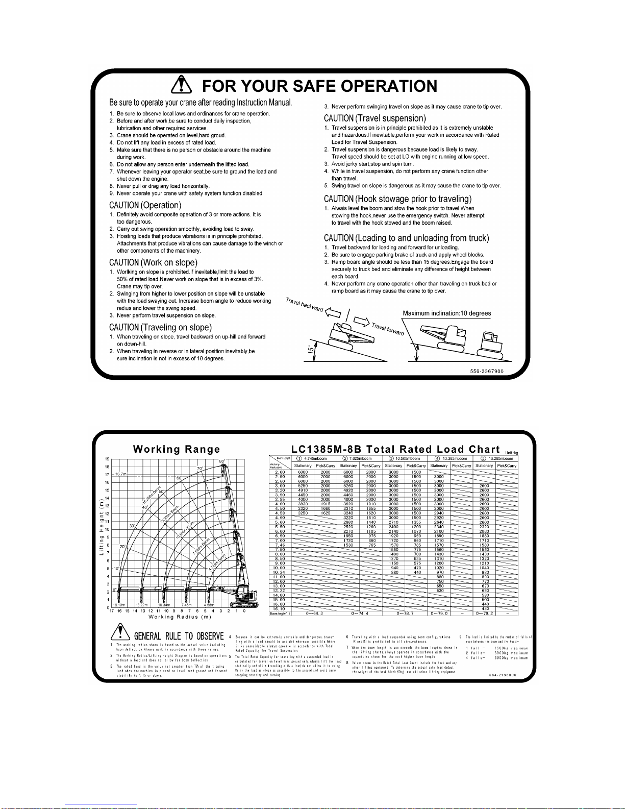
2-36
(1) For your safe operation (556-3367900)
(2) Working Range and Rated total load Chart (584-2198800)

2-37
(3) Moment Limiter Operation (584-2199400)
(4) Warning for Operation, Inspection and Maintenance (584-3469700)
(5) Warning for blade operation (556-4575300)
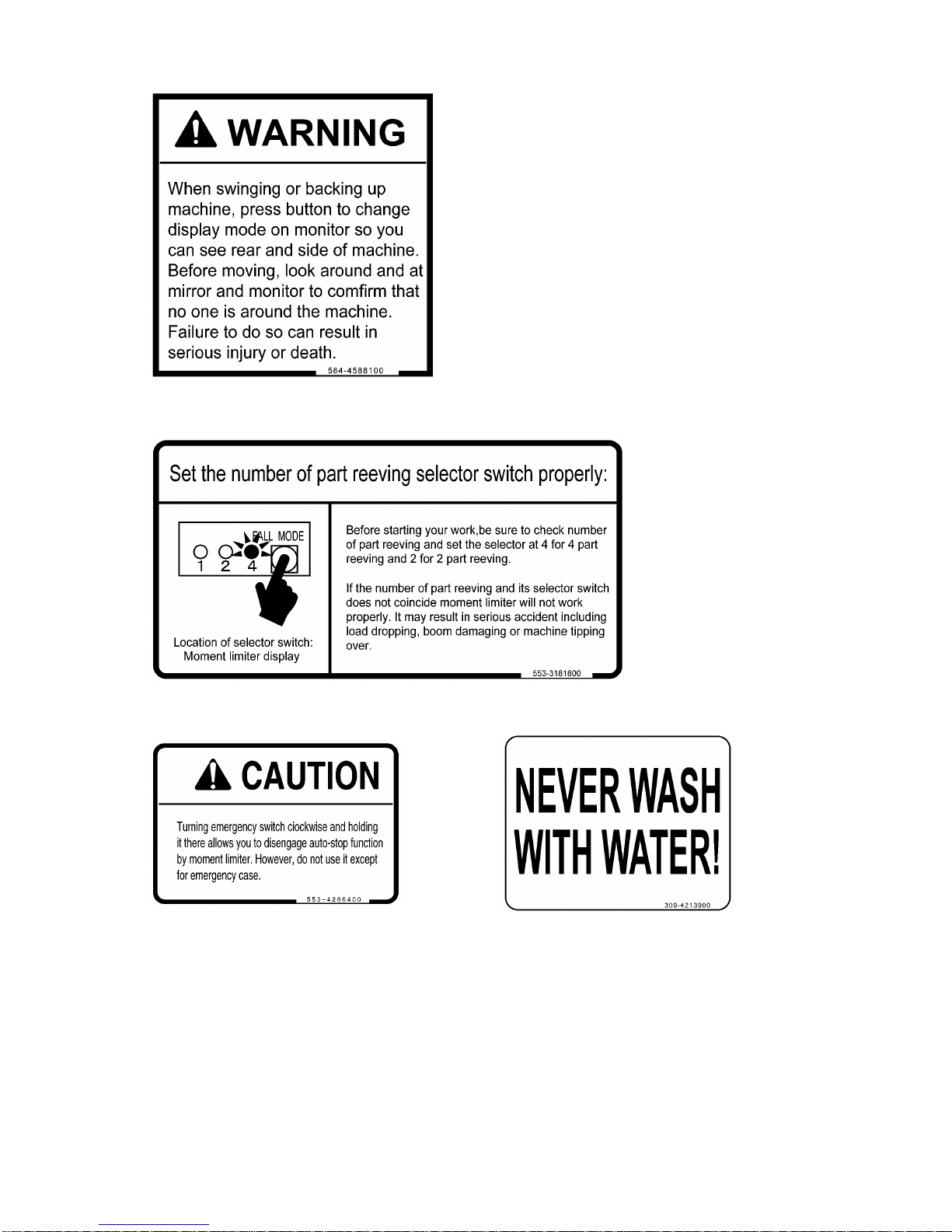
2-38
(6) Warning for Swinging and backing up (584-4588100)
(7) Caution for Number of Parts Reeving Selector Switch (553-3181800)
(8) Caution for Emergency switch (553-4266400) (9) Caution for Wash (300-4213900) (2 places)

2-39
(10) Warning for Window (20U-98-21910) (11) Warning for Front window (09803-03000)
(12) Control Pattern (556-3368100)
(13) Warning Tag (09963-03001)

2-40
(14) Warning for Lifting Eye (103-4576900) (2 places) (15) Do not Stand on here (584-4581700)
(16) Warning for Hydraulic Oil (09653-03001) (17) Caution for fender (09805-03000)
(18) Warning for Coolant (09668-03001) (19) Caution for Engine Hood (09805-13000)
(20) Caution for Rotating portion (09667-03001) (21) Hoisting Load (584-4581600) (3 places)

2-41
(22) Warning (583-4268000) (2 places) (23) Loads on 2-rope machine hoisting (left) (584-4582200)
(24) Loads on 2-rope machine hoisting (right) (584-4582100)
(25) Warning for Lifting position (584-3437800) (26) Warning for winch (553-4267500)
(27) Max. Working Radius and Overall Load at Max. Working Radius (584-3437700)
(28) Connecting Position (09960-00802) (4 places) (29) Lifting Position (09960-00801) (4 places)

2-42
(30) Loads on 4-rope machine hoisting (front) (31) Warning for track tension adjusting
(584-4581800) (2 places) (584-4588200) (2 places)
(32) Loads on 4-rope machine hoisting (rear)
(584-4581900) (2 places)
(33) Keep off Swing Area (09133-23000)
(34) Warning for Battery (09664-30011) (35) Rated Voltage, Current
(556-4496600)

2-43
(36) Machine Weight (584-4582300) (37) Warning for battery cable (098808-03000)
(38) Warning for Accumulator (09659-53000) (39) Warning for Hook Block (553-4267400)
(40) WEEE DERECTIVE LABEL (104-4549500) (14 places)
[LOCATIONS OF WEEE DIRECTIVE LABELS]
(A) Top of relay box
(B) Side of the moment limiter converter
(C) Back side of the monitor display
(D) Side of the moment limiter display
(E) Top of the air conditioner controller
(F) Top of the pump controller
(G) Top of monitor camera
(H) Top of the working status lamp
(J) Top of the battery (2 places)
(K) Top of the inclination sensor
(L) Top of the boom length detector
(M) Top of the boom angle detector
(N) Top of the engine controller

2-44

3-1
OPERATION
1. MACHINE EACH SECTION
3- 2
2. EXPLANATION OF DEVICES
3- 6
3. MACHINE OPERATIONS AND CONTROLS
3-99
4. HANDLING WIRE ROPES
3-169
5. TRANSPORTATION
3-172
6. HANDLING IN COLD WEATHER
3-181
7. LONG-TERM STORAGE
3-183
8. TROUBLES AND ACTIONS
3-184

3-2
1. MACHINE EACH SECTION
1.1 MACHINE EACH UNIT
(1) Boom
(2) Working lamp
(3) Boom derricking cylinder
(4) Winch
(5) Head lamp
(6) Sprocket and traveling motor
(7) Track frame
(8) Idler
(9) Track
(10) Blade cylinder
(11) Blade
(12) Hook block
(13) Over hoist detector
(14) Working status lamp
(15) Rear view mirror
(16) Rear view camera

3-3
1.2 OPERATOR’S COMPARTMENT EQUIPMENT
(1) Radio
(2) Level
(3) Engine emergency stop switch
(4) Lock lever
(5) Left work equipment control lever
(6) Travel pedals
(7) Travel levers
(8) Accelerator pedal
(9) Moment limiter display unit
(10) Moment limiter related switch box
(11) Machine monitor
(12) Right work equipment control lever
(13) Cigarette lighter
(14) Blade control lever
(15) Starter switch
(16) Fuel control dial
(17) Lamp switch
(18) Swing lock switch
(19) Sun roof wiper switch
(20) Room lamp switch
(21) Moment limiter transducer
(22) Emergency pump drive switch
(23) Swing parking brake release switch
(24) Battery disconnect switch

3-4
1.2.1 MACHINE MONITOR
(1) Wiper switch
(2) Buzzer cancel switch
(3) Auto-deceleration switch
(4) Engine coolant temperature monitor
(5) Engine coolant temperature gauge
(6) Hydraulic oil temperature gauge
(7) Service meter/Clock
(8) Hydraulic oil temperature monitor
(9) Working mode monitor
(10) Travel speed monitor
(11) Fuel gauge
(12) ECO gauge
(13)Fuel level monitor
(14) Working mode selector switch
(15) Travel speed selector switch
(16) Window washer switch
(17) Air conditioner control switches
(18) Engine oil pressure monitor
(19) Engine oil level monitor
(20) Message monitor
(21) Air conditioner monitor
(22) Wiper monitor
(23) Swing lock monitor
(24) Engine pre-heating monitor
(25) Auto-decelerator monitor
(26) Charge level monitor
(27) Function switch (F1 to F6)
(28) Maintenance interval monitor
AA: Standard screen BB: All lamps lit up screen CC: Maintenance interval warning screen

3-5
1.2.2 MOMENTOLIMITER RELATED SWITCH BOX
(1) Moment limiter emergency stop cancel switch
(2) Over-hoisting cancel switch
(3) Winch speed selector switch

3-6
2. EXPLANATION OF DEVICES
The following is an explanation of devices needed for operating the machine.
To perform suitable operations correctly and safety, it is important to completely understand methods of
operating the equipment, and the meanings of the displays.
2.1 MACHINE MONITOR
(A) Emergency monitors
(B) Caution monitors
(C) Basic check monitors
(D) Meter display portion, pilot display
(E) Monitor switches portion
NOTES
One of the features of liquid crystal display panels is that there may be black spots (spots that do not
light up) or white spots (spots that stay lit up) on the screen. If there are fewer than 10 black or while
spots, this is not a failure or a defect.
AA: Standard screen
BB: All lamps lit up screen
CC: Maintenance interval warning screen

3-7
2.1.1 BASIC OPERATION OF MACHINE MONITOR
[1] STARTING ENGINE WHEN SITUATION IS NORMAL
• When the starter switch is turned to the ON position, the Opening screen GG is displayed.
• After the Opening screen GG is displayed for 2 seconds, the screen changes to the Check before
starting screen DD.
• After the Check before starting screen DD is displayed for 2 seconds, the screen changes to the Working
mode/Travel mode display screen HH.
• After the Check before starting screen DD is displayed for 2 seconds, the screen changes to the
Standard screen AA.
NOTES
When the engine is started, the battery voltage may suddenly drop depending on the temperature and
the battery condition. If this happens, the display on the machine monitor may momentarily go out, but
this does not indicate any abnormality.
[2] STOPPING ENGINE WHEN SITUATION IS NORMAL
• When the starter switch is turned to the OFF position, the Ending screen JJ is displayed for 5 seconds,
then on the display goes out.
AA: Standard screen JJ: Ending screen
GG: Opening screen
DD: Check before starting screen
HH: Working mode/Travel mode display screen
AA: Standard screen
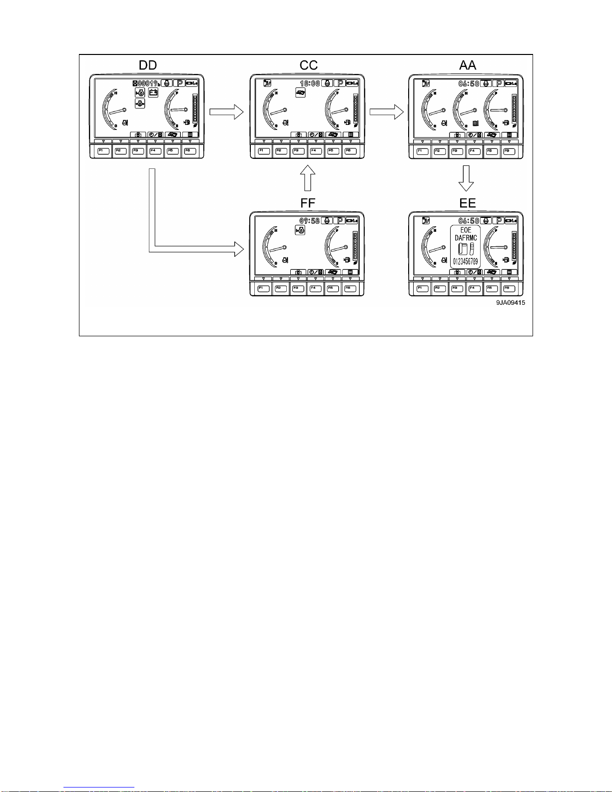
3-8
[3] IF THERE IS ABNORMALITY WHEN STARTING ENGINE
• If there is any abnormality when starting the engine, the Check before starting screen DD changes to the
Maintenance interval warning screen CC, Warning screen FF, or Error screen EE.
• After displaying the Check before starting screen DD for 2 seconds, the screen changes to the
Maintenance interval warning screen CC.
• After displaying the Maintenance interval warning screen CC for 30 seconds, the screen changes to the
Standard screen AA.
• After displaying the Check before starting screen DD for 2 seconds, the screen changes to the Warning
screen FF, or Error screen EE.
DD: Check before starting screen CC: Maintenance interval warning screen AA: Standard screen
EE: Error screen FF: Warning screen

3-9
[4] IF ANY ABNORMALITY OCCURS DURING OPERATION
• If any abnormality OCCURS DURING OPERATION, the Standard screen AA changes to the Warning
screen FF-(1) or the Error screen EE.
• After displaying the Warning screen FF-(1) for 2 seconds, the screen changes to the Warning screen
FF-(2).
AA: Standard screen EE: Error screen FF-(1): Warning screen FF-(2): Warning screen

3-10
NOTES
The colours lighting up the monitors related to the emergency stop items, caution items, and basic
check items are as follows.
Type of monitor
Color when lit up
When normal
When abnormal
At low
temperature
(1)
Engine coolant temperature monitor
Blue
Red
White
(2)
Hydraulic oil temperature monitor
Blue
Red
White
(3)
Fuel level monitor
Blue
Red
--
(4)
Charge level monitor
OFF
Red
--
(5)
Engine oil pressure monitor
OFF
Red
--
(6)
Engine oil level monitor
OFF
Red
--
(7)
Maintenance interval monitor
OFF
Red
--
AA: Standard screen BB: All lamps lit up screen CC: Maintenance interval warning screen

3-11
2.1.2 EMERGENCY STOP ITEMS
If the monitor lights up red, Stop the engine immediately or run at low idle, check applicable
location, then perform necessary actions.
These items should be observed while the engine is running. If there is a problem, the monitor for the
abnormal location lights up and buzzer sounds, perform action immediately.
(1) Engine coolant temperature monitor
(2) Hydraulic oil temperature monitor
(3) Engine oil pressure monitor
[1] ENGINE COOLANT TEMPERATURE MONITOR
This monitor (1) warns operator that the engine coolant temperature has risen.
If the engine coolant temperature becomes abnormally high, the
monitor shows abnormal display (C). The overheat prevention
system is automatically actuated and the engine speed drops.
Stop operations and run the engine at low idling until monitor (1)
change to normal display (B).
• Display (A) at low temperatures: Monitor background (D) is white
• Display (B) at correct temperatures: Monitor background (D) is blue
• Display (C) when condition is abnormal: Monitor background (D) is red
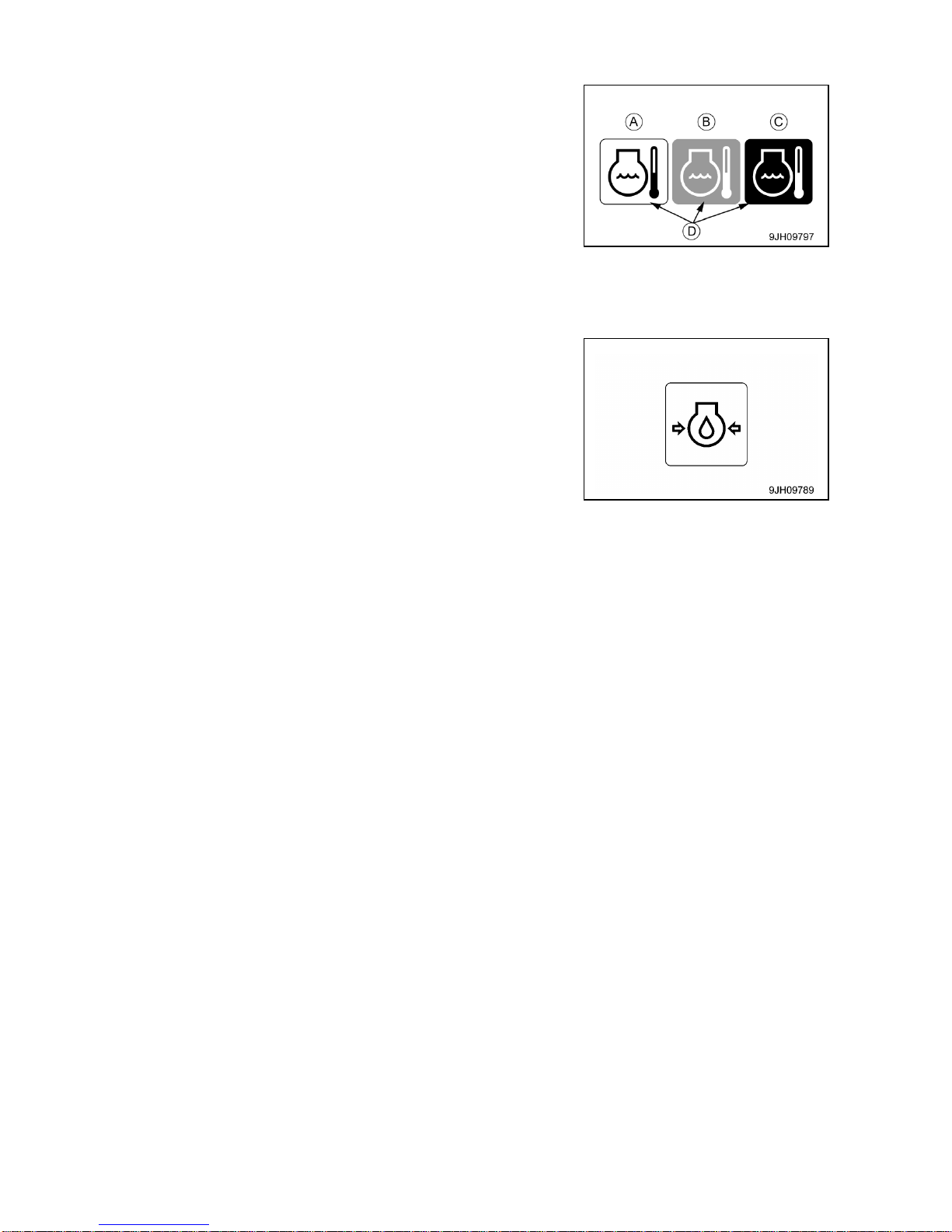
3-12
[2] HYDRAULIC OIL TEMPERATURE MONITOR
This monitor (2) warns operator that the hydraulic oil temperature
has risen.
If the hydraulic oil temperature becomes abnormally high, the
monitor shows abnormal display (C).
Stop operations and stop the engine or run it at low idling until
monitor (2) change to normal display (B).
• Display (A) at low temperatures: Monitor background (D) is white
• Display (B) at correct temperatures: Monitor background (D) is blue
• Display (C) when condition is abnormal: Monitor background (D) is red
[3] ENGINE OIL PRESSURE MONITOR
This monitor (3) warns operator that the engine lubrication oil
pressure has dropped.
If the engine lubrication oil pressure goes below normal level, the
monitor (3) lights up red.
Stop the engine immediately, check the lubrication system and
level of oil in the engine oil pan.

3-13
2.1.3 CAUTION ITEMS
If the warning monitor lights up red, Stop operations as soon as possible and perform
inspection and maintenance of the applicable location. If the warning is ignored, it may lead to
failure.
These are items that should be observed while the engine is running. If any abnormality occurs, the
screen displays the item that needs immediate action.
If there is an abnormality, the monitor for abnormal location lights up red.
(1) Engine coolant temperature monitor
(2) Hydraulic oil temperature monitor
(3) Fuel level monitor
(4) Charge level monitor
[1] ENGINE COOLANT TEMPERATURE MONITOR
If this monitor (1) shows low-temperature display (A), carry out the
warm-up operation.
For details, see “Operation 3.4.1 Engine Warm Up”.
This monitor (1) will show normal display (B), so carry out the
warm-up operation for engine.
This monitor (1) will show abnormal display (C), stop operations
and run the engine at low idling until monitor (1) change to normal
display (B).
• Display (A) at low temperatures: Monitor background (D) is white
• Display (B) at correct temperatures: Monitor background (D) is blue
• Display (C) when condition is abnormal: Monitor background (D) is red
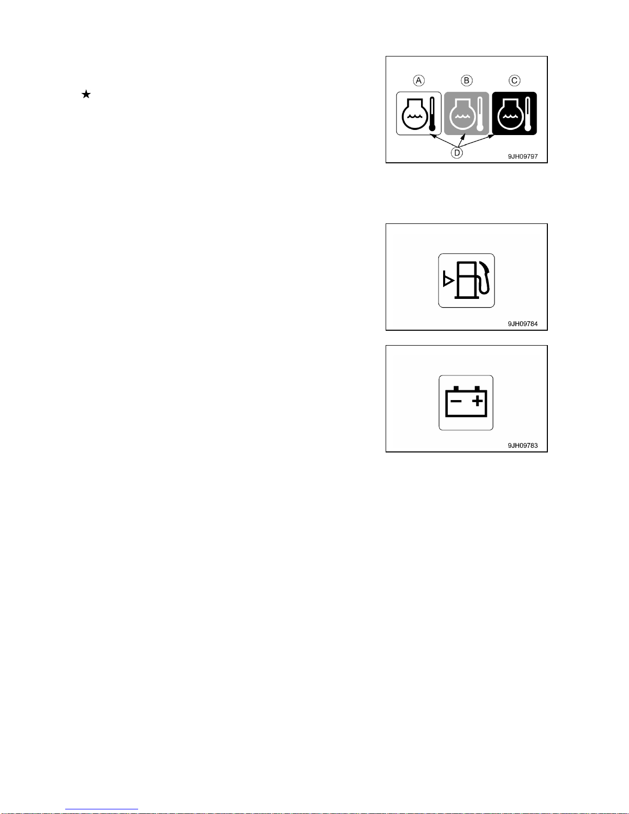
3-14
[2] HYDRAULIC OIL TEMPERATURE MONITOR
If this monitor (2) shows low-temperature display (A), carry out the
warm-up operation.
For details, see “Operation 3.4.2 Hydraulic Equipment Warm
Up”.
This monitor (2) will show normal display (B), so carry out the
warm-up operation for hydraulic equipment.
• Display (A) at low temperatures: Monitor background (D) is white
• Display (B) at correct temperatures: Monitor background (D) is blue
• Display (C) when condition is abnormal: Monitor background (D) is red
[3] FUEL LEVEL MONITOR
This monitor (3) lights up to warn that the operator that the level in
the fuel tank is low.
When the remaining fuel level reaches approx. 33 liters, the
monitor lights up red, so add fuel as soon as possible.
[4] CHARGE LEVEL MONITOR
This monitor (4) warns the operator that there is an abnormality in
the charging system when the engine is running.
If the battery is not being charged properly while the engine is
running, monitor (4) lights up red.
If monitor (4) lights up red, check the V-belt for looseness. If any
abnormality is found, perform the necessary actions.
For details, see “Operation 9.5 Other Trouble”.

3-15
2.1.4 BASIC CHECK ITEMS
These monitor do not guarantee the condition of the machine.
Do not simply rely on the monitor when carrying out checks before starting (daily inspection).
Always get off the machine and check each item directly.
Displays basic items among the check before starting items that must be checked before starting the
engine. If there is any abnormality, monitor for the location of abnormality will light up.
(1) Engine oil level monitor
(2) Maintenance interval monitor
[1] ENGINE OIL LEVEL MONITOR
This monitor (1) warns the operator that the oil level in the engine
oil pan has dropped.
If oil level in the engine oil pan is low, the monitor lights up red, so
check the oil level, and add oil.
[2] MAITENANCE INTERVAL MONITOR
This monitor (2) lights up when the maintenance time gets close
and remains lit after the maintenance time has already passed.
• Lit yellow: The maintenance interval is due within 30 hours.
• Lit red: The maintenance interval has already passed.
This monitor (2) Lights up when starter switch is turned to the ON
position. It goes off after 30 seconds and display changes to the
Standard screen.
NOTES
• For details of the method of confirming the maintenance interval , see “Operation 2.1.7 [3]
Maintenance Slector Switch”.
•If it is desired to change settings for the maintenance interval, have us or our sales service agent
change the settings.

3-16
2.1.5 METER DISPLAY PORTION
PILOT DISPLAY
(1) Engine pre-heating monitor
(2) Swing lock monitor
(3) Wiper monitor
(4) Auto-deceleration monitor
(5) Working mode monitor
(6) Travel speed monitor
(7) Air conditioner monitor
(8) Message monitor
(9) Idle stop guidance
GAUGE AND METER
(10) Engine coolant temperature gauge
(11) Hydraulic oil temperature gauge
(12) Fuel level gauge
(13) Service meter/Clock
(14) ECO gauge
[PILOT DISPLAY]
• The pilot display at the top of the screen consists of the pilot lamps to confirm the actuation of each
function.
• When the starter switch is turned to the ON position, the pilot lamp lights up when the display items are
functioning.
[1] ENGINE PRE-HEATING MONITOR
This monitor (1) is displayed when preheating the engine before
starting the engine in temperature below 0 degrees C.
In cold weather, when the starter switch is turned to the HEAT
position, the preheating monitor lights up. After lighting up for
approx. 30 seconds, it starts to flash to inform the operator that the
preheating has been completed. After flashing for approx. 10
seconds, the monitor goes out.

3-17
[2] SWING LOCK MONITOR
This monitor (2) informs the operator that the swing lock is being
actuated.
Actuated: Lights up
When the swing lock switch is turned ON (Actuated), the monitor
lights up.
When the swing parking brake release switch is set to the FREE
position, the monitor flashes.
For detail of positions of the swing parking brake release switch,
see “Operation 1.2 Operator`s Compartment Equipment”.
NOTES
The swing motor is equipped with a disc brake that mechanically stops the rotation. When the swing lock
monitor is lit up, the brake remains applied.
[3] WIPER MONITOR
This monitor (3) indicates operating status of the wiper.
The monitor display when wiper switch is operated, as follows.
• Monitor ON lights up: Wiper moves continuously
• Monitor INT Lights up: Wiper moves intermittently
• Monitor OFF: Wiper stops.
For detail of positions of the wiper switch, see “Operation 1.2
Operator`s Compartment Equipment”.
[4] AUTO-DECELERATION MONITOR
This monitor (4) shows if the auto-deceleration is being actuated.
The monitor display when auto-deceleration switch is operated, as
follows.
• Monitor ON: Auto-deceleration actuated
• Monitor OFF: Auto-deceleration canceled
For detail of positions of the auto-deceleration switch, see
“Operation 1.2 Operator`s Compartment Equipment”.
[5] WORKING MODE MONITOR
This monitor (5) displays the setting of the working mode.
The monitor display is as follows according to the operation of the
working mode switch.
• P mode: For heavy-load operations
• E mode: For operations with emphasis on fuel consumption
• L mode: For fine control operations
• B mode: Not available for this machine
• ATT mode: Not available for this machine
For detail of positions of the working mode switch, see “Operation 1.2 Operator`s Compartment
Equipment”.
NOTES
With this machine, avoid to set the working mode switch to B mode (Breaker operation) or ATT mode
(Crusher operation) .

3-18
[6] TRAVEL SPEED MONITOR
This monitor (6) shows the setting for the travel speed.
The monitor display is as follows according to the operation of the
travel speed selector switch.
• Monitor Lo: Low-speed travel
• Monitor Hi: High-speed travel
For detail of positions of the travel speed selector switch, see
“Operation 1.2 Operator`s Compartment Equipment”.
[7] AIR CONDITIONER MONITOR
This monitor (7) displays the working status of the air conditioner.
• Monitor lit up: Air conditioner ON
• Monitor off: Air conditioner OFF
[8]MESSAGE MONITOR
The message monitor is not available for this machine.
This monitor (8) remains lit throughout operation.
[9] IDLE STOP GUIDANCE
If the levers are not operated for more than 5 minutes, and the
engine is idling, the idling stop message is displayed on the
monitor. When waiting for work or stopping work for short periods,
stop the engine to reduce unnecessary fuel consumption.
The idling stop message screen returns to the standard screen if
any lever is operated again or when function switch (F5) (Back) is
pressed.

3-19
[GAUGE AND METER]
[10] ENGINE COOLANT TEMPERATURE GAUGE
This meter (10) shows the engine coolant temperature.
During normal operations, the indicator should be in the green
range.
If the indicator goes beyond red range (A) during operations, the
overheat prevention system is actuated.
• (A) - (B): Red range
• (A) - (C): Green range
• (C) - (D): White range
NOTES
• The overheat prevention system is actuated as follows.
• Red range (A) position: Engine coolant temperature monitor (E) shows abnormality display
• Red range (B) position: Engine speed changes to low idling, engine coolant temperature monitor (E)
shows abnormality display, alarm buzzer sounds at same time.
The overheat prevention system continues to work until the indicator enters the green range.
•When the engine is started, if the indicator is at position (C), engine coolant temperature monitor E)
shows the low-temperature display.
If this happens, carry out the warm-up operation. For detail, see “Operation 3.4.1 Engine Warm-Up”.
• Display (G) at low temperatures: Monitor background (K) is white
• Display (H) at correct temperatures: Monitor background (K) is
blue
• Display (J) when condition is abnormal: Monitor background (K)
is red

3-20
[11] HYDRAULIC OIL TEMPERATURE GAUGE
This meter (11) shows the hydraulic oil temperature.
During normal operations, the indicator should be in the green
range.
If the indicator enters the red range (A) during operations, the
hydraulic oil temperature is 102 degrees C or more. Run the
engine at low idling or stop it and wait for the hydraulic oil
temperature to go down.
• (A) - (B): Red range
• (A) - (D): Green range
• (D) - (C): White range
NOTES
When the indicator reaches red range (A), the hydraulic oil temperature is as follows.
• Red range (A) position: 102 degrees C or more
• Red range (B) position: 105 degrees C or more
When the indicator is in red range (A) – (B), hydraulic oil temperature monitor (E) shows the abnormality display. When the engine is started, if the indicator is at position (C) and the hydraulic oil temperature
is 20 degrees C, hydraulic oil temperature monitor (E) shows the low-temperature display. If this
happens, carry out the warm-up operation. For detail, see “Operation 3.4.2 Hydraulic Equipment
Warm-Up”.
• Display (G) at low temperatures: Monitor background (K) is white
• Display (H) at correct temperatures: Monitor background (K) is
blue
• Display (J) when condition is abnormal: Monitor background (K)
is red
[12] FUEL GAUGE
This gauge (12) shows the amount of fuel remaining in the fuel
tank.
During normal operations, the indicator should be in the green
range.
If the indicator starts to enter red range (A) during operation, there
is less than 52 liters of fuel remaining, so carry out inspection and
add fuel.
• (A) - (B): Red range
• (A) - (C): Green range
NOTES
• When the indicator reaches red range (B), there is less than 33 liters of fuel remaining.
• When the indicator is in red range (B), fuel level monitor (D) lights up red.
• The correct fuel level may not be displayed for a short time when the starter switch is turned ON, but
this is not an abnormality.

3-21
[13] SERVICE METER/CLOCK
This meter (13) shows the total hours of operation of the machine
or the present time.
When the engine is running, the service meter advances even if
the machine is not moving. The service meter advances 1 for
every hour that the machine is working, regardless of the engine
speed.
• When the standard screen is being displayed, if function switch
F4 is pressed, it is possible to switch between the clock display
and the service meter display.
• Clock display (12-hour or 24-hour displays are available)
To set or correct the time, press function switch F6 (user mode
switch).
[14] ECO GAUGE
This gauge (14) shows the working load status.
When the gauge is in green range (A), the work load is light to
medium. When the gauge is in orange range (B), the load is heavy.
NOTES
When the gauge enters the orange range (B), there is no
abnormality on the machine, but to protect the environment,
reduce the engine output to a point where there is no adverse
effect on the operation. Generally, carry out energy-saving
operations in the green range (A). Reducing the frequency of
the travel also helps to save energy. Consider the best way of
saving energy.

3-22
2.1.6 MONITOR SWITCHES PORTION
(1) Working mode selector switch
(2) Auto-deceleration switch
(3) Travel speed selector switch
(4) Wiper switch
(5) Window washer switch
(6) Buzzer cancel switch
(7) Function switch
(8) Air conditioner switch
[1] WORK MODE SELECTOR SWITCH
Use this switch (1) to set the movement or power of the crane.
The operation becomes easier if the mode is selected to match the
content of the operation.
• P mode: For heavy-load operations
• E mode: For operations with emphasis on fuel consumption
• L mode: For fine control operations
• B mode: Not available for this machine
• ATT mode: Not available for this machine
NOTES
B mode (Breaker operation) and ATT mode (Crusher operation)
of this work mode selector switch are not availble for this
machine.
• When the monitor first appears, it is automatically set to the mode
in use when it was started the previous time.
• Press switch (1) to display the working mode selection screen.
For each set mode, the pilot monitor at the top right of the monitor
display shows P, E, L, B, ATT.
NOTES
If you want to have automatic setting of the P, E or L mode when starting, please contact us or our sales
service agency to change the setting.

3-23
[PROCEDURE FOR OPERATION]
1. If working mode selector switch (1) is pressed, the working
mode screen is displayed on the monitor.
2. Press function switches (F3) or (F4) at the bottom of the screen
or working mode selector switch (1) to change the mode
selection one at a time.
NOTES
• If no switch is touched for more than 5 seconds, the selected
work mode is automatically set as the working mode and the
screen changes to Steps 3 and Steps 4.
• To return to the standard screen without changing the working
mode, press function switch (F5).
3. After selecting the desired mode, press function switch (F6) and
the mode is displayed in the center of the monitor display.
(Example: If power mode is selected: P)
4. After 2 seconds, the pilot monitor display at the top right of the
screen is highlight in orange.
NOTES
After 2 seconds, the screen return to the standard screen.
The monitor display highlighted in orange in steps 4 return to
blue.
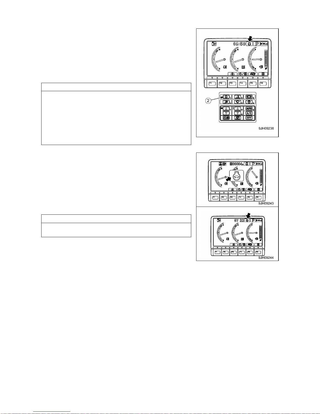
3-24
[2] AUTO-DESELERATION SWITCH
If the control levers are neutral, this switch (2) automatically lowers
the engine speed and returns on the function to reduce fuel
consumption.
• Monitor ON: Auto-deceleration ON
• Monitor OFF: Auto-deceleration OFF
Each time the switch is pressed, the auto-deceleration is switched
between ON and OFF.
NOTES
[AUTO-DESELERATION FUNCTION]
When the auto-deceleration function is ON, if the work
equipment and travel levers are returned to the N position, the
engine speed drop after 4 seconds from the operating speed to
idling speed.
This makes it possible to reduce fuel consumption.
If any lever is operated when the machine is in this condition,
engine speed will return to the previous operating speed to make
it possible to perform operation.
1. When auto-deceleration switch (2) is pressed and the
auto-deceleration function is returned ON, the mode is displayed
in the center of the monitor display, and after 2 seconds, the
screen returns to the standard screen.
2. On the standard screen, the auto-deceleration monitor lights up.
NOTES
When the auto-deceleration is OFF, it does not light up.

3-25
[3] TRAVEL SPEED SELECTOR SWITCH
• When loading or unloading the machine on a trailer, always travel at low speed (set to Lo).
Never operate the travel speed selector switch when traveling.
• If the travel speed selector switch is operated when the machine is traveling, the machine may
deviate to one side even when it is traveling in a straight line. Always stop the machine before
changing the travel speed.
• The area at the rear of the machine is a blind spot. Always use the rear view camera to check
the area at the rear of the machine before traveling in reverse.
This switch (3) is used to set the travel speed to 2 stages.
Each time that the switch is pressed, the display changes Lo → Hi
→ Lo in turn.
• Monitor Lo: Low –speed travel
• Monitor Hi: Hi-speed travel
When the engine is started, the speed is automatically set to Lo.
NOTES
When traveling in high speed (Hi), if travel power is needed,
such as when traveling on soft ground or on slopes, the speed
automatically switches to low speed (Lo), so there is no need to
operate the switch. The monitor display stays at Hi.
NOTES
• Each time travel speed selector switch (3) is switched, the
mode is displyed on the monitor display, and after 2 seconds,
the screen returns to the standard screen.
• If the moment limter displays the actual laod of 0.5 tons or more
even once, traveling in high speed is not available despite the
monitor display stays at "Hi". When traveling in high speed is
required, always keep the actual load value within 0.2 tons.
• While the boom length in the moment limiter display is 5.2
meters or less and the boom angle is 5.0 degrees or less, travel
speed selector switch can be turned to hi-speed travel,
regardless of the actual load value.
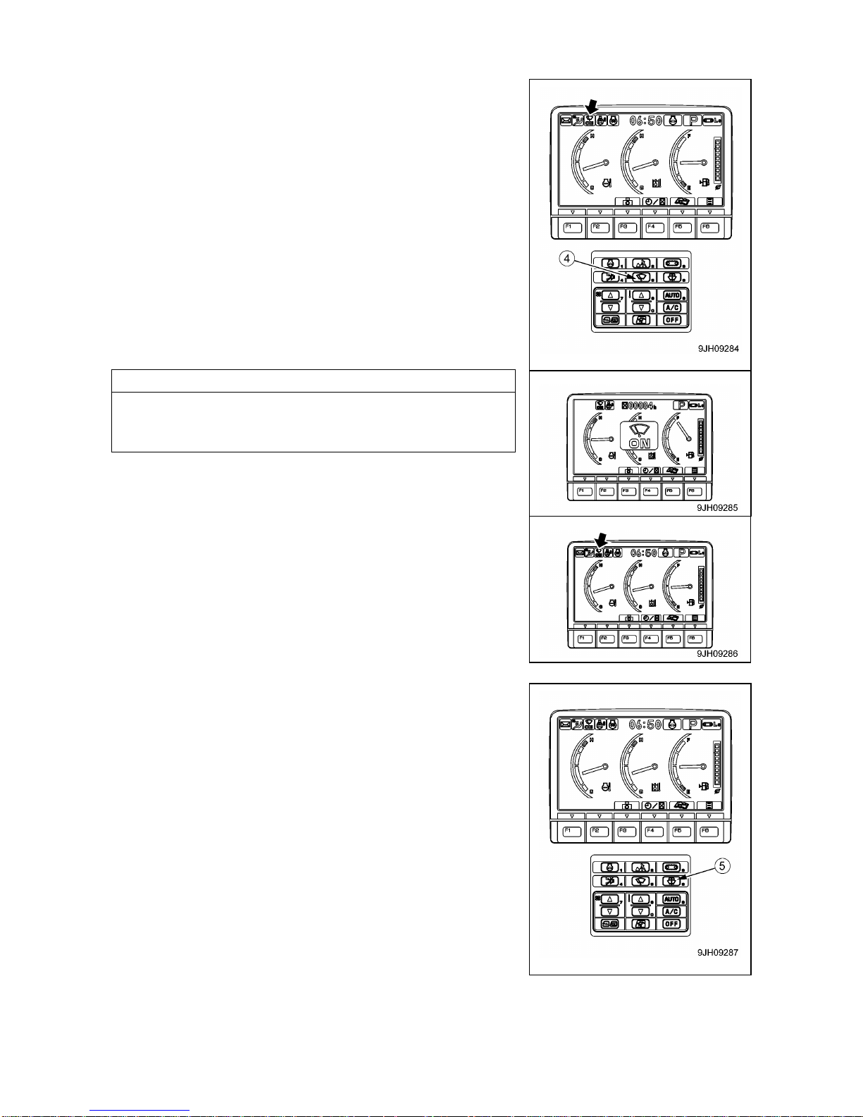
3-26
[4] WIPER SWITCH
This switch (4) actuates the front window wiper.
Each time the switch is pressed, it changes ON→INT→STOP
(OFF).
• Monitor INT: Wiper operates intermittently
• Monitor ON: Wiper operates continuously
• Monitor OFF: Wiper stops
NOTES
Each time wiper switch (4) is pressed, the mode is displyed in
the center of the monitor display, and after 2 seconds, the screen
returns to the standard screen.
[5] WINDOW WASHER SWITCH
If this switch (5) is kept continuously pressed; window washer fluid
is sprayed out on the front glass. When the switch is released, the
spray stops.
• If switch (5) is kept pressed when the wiper is stopped, the
window washer fluid will spray, and at the same time, the wiper
will be actuated continuously. When switch (5) is released, the
wiper will continue to operate for 2 cycles, and then stop.
• If the wiper is moving intermittently and switch (5) is kept pressed
continuously, window washer fluid will spray, and at the same
time, the wiper will be actuated continuously. When switch (5) is
released, the wiper will continue to operate for 2 cycles, and then
return to intermittent operation.

3-27
[6] BUZZER CANCEL SWITCH
This switch (6) is pressed, the warning buzzer for the abnormal
warning item stops.
[7] FUNCTION SWITCHES
Function switches (7) consist of 6 switches (F1 to F6). The function
of each switch differs according to the content of each screen.
When the monitor display shows the standard screen, the
functions are displayed as follows.
Switch (F3): Camera screen selector switch
Switch (F4): Service meter/time display selector switch
Switch (F5): Maintenance mode switch
Switch (F6): User mode switch
Switch (F1) and (F2) are auxiliary switches for expanded functions.
NOTES
For explanation of each switch, see “Operation 2.1.7 Handling
Function Switches”.
[8] AIR CONDITIONER SWITCH
The air conditioner switches (8) consist of 9 switches.
NOTES
For explanation of each switch, see “Operation 2.6 Air
Conditioner Controls”.

3-28
2.1.7 HANDLING FUNCTION SWITCHES
• The function switches (A) at the bottom of the monitor display
consist of 6 switches (F1 – F6). The function of each switch differs
according to the content of each screen.
• The function of switches (A) on each screen can be confirmed by
guidance icons (B) displayed on top of each switch.
• If there is no display in guidance icon (B), even if switch (A) is
pressed, it will not function.
• Even if guidance icon (B) is pressed, it will not function. Press
switch (A) immediately below the guidance icon display to
operate the function.
The operation of the function switches if the initial screen is the standard screen is as follows.
[1] CAMERA SCREEN SELECTOR SWITCH
Press the switch (F3) to switch to the camera screen display.
[OPERATING CAMERA SCREEN DISPLAY]
The following explanation is the method used to display the
camera image on the monitor.
• On the standard screen, if switch (F3) is pressed, the image
display screen is displayed.
• Press the switch (F5) to return to the standard screen.
[OTHER MODE OPERATIONS WHEN DISPLAYING CAMERA IMAGE]
Even during the camera display, it is possible to operate other
modes.
• The air conditioner can be operated.
If the air conditioner switch is operated, the screen switches to the
air conditioner control screen. If the screen switches to the air
conditioner control screen, press function switch (F6) to return to
the camera image display screen. In addition, if no operation is
carried out for 5 seconds after the screen switches to the air
conditioner control screen, the screen automatically returns to the
camera image display screen.
NOTES
For details of the operation of the air conditioner, see “Operation
2.6 Air Conditioner Controls”.

3-29
• It is possible to change the working mode by pressing the working
mode selector switch.
When the working mode is changed, the screen returns
automatically to the camera image display screen. When this
happens, the pilot monitor display at the top centre of the monitor
screen is highlighted in yellow for 2 seconds, then returns to blue.
NOTES
For details of the method of using the working mode selector
switch, see “Operation 2.1.6 Monitor switch portion [1] Working
Mode Selector Switch”.
• It is possible to change the travel speed by pressing the travel
speed selector switch.
When the travel speed is changed, the pilot monitor display at the
top right of the monitor screen is highlighted in yellow for 2
seconds, then returns to blue.
NOTES
For details of the method of using the working mode selector
switch, see “Operation 2.1.6 Monitor switch portion [3] Travel
Speed Selector Switch”
• Press the auto-deceleration switch to return the auto-deceleration function ON/OFF.
Even if the auto-deceleration switch is pressed, the camera
image display screen does not switch to another screen or return
to the standard screen display.
• It is possible to press the buzzer cancel switch to stop the alarm
buzzer for the warning item where there is an abnormality.
Even if the buzzer cancel switch is pressed, the camera image
display screen does not switch to another screen or return to the
standard screen display.
• Press the wiper switch and washer switch to operate the wiper
and washer.
Even if the wiper switch or washer switch is pressed, the camera
image display screen does not switch to another screen or return
to the standard screen display.

3-30
[ACTION WHEN WARNING IS GENERATED WHEN DISPLAYING CAMERA IMAGE]
• If an error or alarm occurs while the camera image is being
displayed, the error monitor or alarm monitor is displayed at the
top left of the screen and flashes.
• If the error monitor or alarm monitor is displayed, press switch
(F6), return to the standard screen, and check the content of the
error or alarm display.
When the error monitor is flashing, if no lever is operated for more
than 10 seconds, the screen automatically returns to the standard
screen.
When the screen returns to the standard screen, the error monitor
at the top left of the screen goes out and the error or alarm is
displayed in the center of the screen.
• If an error monitor is displayed, move the machine, set it in a
safety posture, and then have inspection carried out immediately.
NOTES
For details of the content of the warning display, see “Operation
2.1.4 basic Check Monitors”, “Operation 2.1.3 Caution
Monitors”, “Operation 2.1.2 Emergency Stop Monitors”, and
“Operation 10. Troubles and Actions”.

3-31
[2] SERVICE METER/CLOCK DISPLAY SELECTOR SWITCH
• On the standard screen, it is possible to press the function switch
(F4) to switch the service meter and clock display at the top of the
monitor display.
• When the time is being displayed, press the function switch (F4)
to switch to the service meter display.
[3] MAINTENANCE MODE SELECTOR SWITCH
When function switch (F5) is pressed on the standard screen, the
monitor display screen switches to the maintenance mode screen.
The items on the maintenance display are as follows.
Maintenance items
Default maintenance
interval settings (h)
Engine oil change
500
Engine oil filter change
500
Fuel main filter change
1000
Fuel pre-filter change
500
Hydraulic oil filter change
1000
Hydraulic tank breather change
500
Damper case service
1000
Final drive case oil change
1000
Swing machinery case oil change
1000
Hydraulic oil change
5000
(a): Maintenance items
(b): Default maintenance interval
settings (h)
(c): Time remaining until mainte-
nance (h)

3-32
[OPERATIONS ON MAINTENANCE LIST SCREEN]
On the maintenance list screen, it is possible to carry out the
following operations with function switches (F1 to F6).
• Switch (F1): Displays next page. After the last page, it displays
the first page.
• Switch (F2): Displays previous page. After the first page, it
displays the last page.
• Switch (F3): Moves to next item (1 line down). After the last line, it
moves to the first line on the next page.
• Switch (F4): Moves to previous item (1 line up). After the first line,
it moves to the last line on the previous page.
• Switch (F5): Returns to standard screen.
• Switch (F6): If this switch is kept pressed, the screen changes to
the screen for resetting the remaining time for the
selected item (item highlighted in yellow).
NOTES
When resetting the remaining time, keep switch (F6) pressed for at least 1.5 seconds. If switch (F6)
isnot kept pressed for at least 1.5 seconds, the switch operating sound can be heaard, but the screen
does not switch to the screen for resetting the remaining time.
• If no switch is operated for 30 seconds on the maintenance list screen, the screen automatically returns
to the standard screen.
• On the maintenance list screen, if the time remaining until maintenance for any item is less than 30 hours,
the remaining time display is highlighted in yellow. If the time remaining until maintenance becomes 0
hours, the remaining time display is highlighted in red.
• If you want to change the setting for the maintenance interval, please consult us or our sales service
agency.
[OPERATIONS ON MAINTENANCE INTERVAL RESET SCREEN]
On the maintenance list screen, if switch (F6) is kept pressed for at 1.5 seconds, the screen changes to
the maintenance time reset screen.
Reset the remaining time on this screen.
1. Press switch (F6) when the reset screen is in the condition
shown in the diagram on the right. The screen switches to the
reconfirmation screen.
NOTES
• It is desired to cancel the reset, press switch (F5). The screen
returns to the maintenance list screen.
• On the reset screen, if no switch is operated for more than 30
seconds, the screen automatically switches to the maintenance
list screen.
2. The reconfirmation screen shown on the right is displayed.
3. If switch (F6) is pressed again. The remaining time is reset and
the screen switches to the maintenance list screen.
NOTES
• If it is desired to cancel the reset, press switch (F5). The screen
returns to the maintenance list screen.
• On the reconfirmation screen, if no switch is operated for more
than 30 seconds, the screen automatically switches to the
maintenance list screen.
(a): Maintenance items
(b): Default maintenance interval
settings (h)
(c): Time remaining until mainte-
nance (h)

3-33
[4] USER MODE SELECTOR SWITCH
When the switch (F6) pressed, the monitor display screen
switches to the setting mode screen for the machine.
On the user menu screen, it is possible to carry out the following
operations with function switches (F3 to F6).
• Switch (F3): Moves to next item (1 line down). When on the last
line, it moves to the first line on the next page.
• Switch (F4): Moves to previous item (1 line up). When on the first
line, it moves to the last line on the previous page.
• Switch (F5): Returns to standard screen.
• Switch (F6): Switches to setting screen for selected item.
NOTES
If no switch is operated for 30 seconds on the user menu screen,
the screen automatically returns to the previous screen.
• The following item can be set.
(a): Not available for this machine
(b): Not available for this machine
(c): Screen adjustment
(d): Clock adjustment
(e): Language selection
(f): Economy mode adjusting
The operation for setting (a) to (f) as follows.

3-34
(c) Adjusting screen
Use this screen adjustment menu to adjust the brightness, contrast,
and back light of the screen.
1. On the standard screen, presses switch (F6).
2. Select screen adjustment on the user menu screen, then press
switch (F6). The screen switches to the selection menu screen
for screen adjustment.
NOTES
It is possible to adjust the brightness, contrast, and back light of
the camera image display screen on this menu.
3. Select item to be adjusted (a) or (b) from the selection menu
screen for screen adjustment, then press switch (F6).
The screen switches to the setting screen for the selected item.
On the mode selection screen shown on the right, it is possible
to carry out the following operations with switches (F3 to F6).
• Switch (F3): Moves to next item (1 line down).
• Switch (F4): Moves to previous item (1 line up).
• Switch (F5): Returns to user menu screen.
• Switch (F6): Switches to setting screen for selected item.
4. Use switches (F2 to F6) to adjust the brightness, contrast, and
back light of the selected screen.
(1) Adjusting standard screen
• If the light switch is at night mode ON, and the standard screen
is adjusted, it is possible to adjust the brightness of the monitor
screen (night mode).
• If the switch is at day mode ON or OFF, and the standard
screen is adjusted, it is possible to adjust the brightness of the
monitor screen (day mode).
(2) Adjusting camera screen
• The background when adjusting the camera image is the
image for the No. 1 camera.
• When displaying the camera screen, the screen may become
dark if the image is on snow. In such cases, we recommend
adjustment of the screen.
On the screen for items (1) or (2), it is possible to carry out the
following operations with switches (F2 to F6).
• Switch (F2): Resets all adjusted values to default value.
• Switch (F3): Indicator of selected item moves 1 segment to left.
• Switch (F4): Indicator of selected item moves 1 segment to right.
• Switch (F5): Returns to user menu screen.
• Switch (F6): Accepts change and switches to next item setting.
(a): Standard screen adjustment
(b): Camera screen adjustment

3-35
(d) Clock Adjustment
On this clock adjustment menu, it is possible to change the setting of the clock displayed on the pilot
monitor of the standard screen.
1. On the standard screen, presses switch (F6).
2. Select “Clock Adjustment” on the user menu screen, then
presses the switch (f6). The screen switches to the time
adjustment selection menu screen.
The following 3 items can be changed.
• (a): Clock setting
• (b): 12/24 hour display mode
• (c): Daylight saving time
3. On the clock adjustment selection screen, it is possible to carry
out the following operations with switches (F3 to F6).
[Time]
Adjust the hour setting.
(1) If “Time” (a) is not highlighted in yellow, press switch (F6) to
highlight “Time” (a) in yellow. When this is done, hour display
(b) changes to orange.
(2) Adjust hour display (b) with the switches as following. If it is
not necessary to change the hour setting, presses switch (F6).
• Switch (F3): Time advances 1 hour.
• Switch (F4): Time goes back 1 hour.
• Switch (F5): Cancels change and returns to user menu screen.
• Switch (F6): Accepts change and goes to setting for minutes.
(a): Time (b): Hour (c): Minute

3-36
(3) When minute display (c) is highlighted in orange, operate the
switches as follows to adjust minute display (c).
(4) If it is not necessary to change the minute setting, press
switch (F6). If the time has been changed, always press
switch (F6).
• Switch (F3): Time advances 1 minute.
• Switch (F4): Time goes back 1 minute.
• Switch (F5): Cancels change and returns to user menu
screen.
• Switch (F6): Accepts change and goes to setting for 12/24
hour display mode minutes.
[12/24h Mode]
Choose either a 12-hour display (am/pm) or a 24-our display.
(1) If “12h/24h Mode” (a) is not highlighted in yellow, press
switch (F6) to highlight “12h/24h Mode” (a) in yellow.
(2) Change the “12h/24h Mode” with the switches as follows.
The selected display mode (b) or (c) is highlighted in green.
• Switch (F3): Moves 1 item to left.
• Switch (F4): Moves 1 item to right.
• Switch (F5): Cancels change and returns to user menu
screen.
• Switch (F6): Accepts change and goes to setting for
“Daylight Saving Time” minutes.
If the setting has been changed, always press switch (F6).
[Daylight Saving Time (Summer time)]
(1) If “Daylight Saving Time” is turned ON (a), the clock display
becomes 1 hour earlier. If “Daylight Saving Time” is turned
OFF (b), the clock display returns to the set time.
The selected display mode is highlighted in green.
(2) Change the “Daylight Saving Time” with the switches as
follows.
• Switch (F3): Moves 1 item to left.
• Switch (F4): Moves 1 item to right.
• Switch (F5): Cancels change and returns to user menu
screen.
• Switch (F6): Accepts change and goes to setting for “Time”
If the setting has been changed, always press switch (F6).
NOTES
Daylight saving time or summer time means moving the clock
forward 1 hour to take advantage of the fact that the sun rises
early in summer. This system is used in many countries during
the summer.
(a) 12h/24h Mode
(b): 24-hour display
(c): 12-hour display (am/pm)
(a): ON (b): OFF
(a): Time (b): Hour (c): Minute
 Loading...