


585E-OM1712-02
OPERATION MANUAL
CRAWLER CRANE
Serial No. 7048 and up
Unsafe use of this machine may cause serious injury or death. Operators
must read this manual before operating this machine. This manual should
be kept near the machine for reference and periodically reviewed by all
personnel who will come into contact with it.
NOTICE
MAEDA has Operation Manuals written in some other languages. If a
foreign language manual is necessary, contact your local distributor for
availability.
CC1485S
-1


i
CONTENTS
Item
Page
INTRODUCTION
1
1. INTRODUCTION 2
2. FOR SAFE USE OF THE MACHINE 3
3. MACHINE OVERVIEW 4
3.1 SPECIFIED OPERATIONS
4
3.2 MACHINE STRUCTURE 4
3.3 MACHINE FUNCTIONS
5
4. QUALIFICATION FOR OPERATION 6
4.1 QUALIFICATION FOR CRANE OPERATION 6
5. CRANETERMINOLOGY 7
5.1 TERMS AND DEFINITIONS 7
5.2 DIAGRAM OF WORKING RADIUS AND LIFTING HEIGHT
8
5.3 RATED TOTAL LOAD CHART 9
SAFETY
13
1. BASIC PRECAUTIONS 14
1.1 PRECAUTIONS BEFORE STARTING WORK 14
1.2 PREPARING FOR SAFE OPERATION 15
1.3 PRECAUTIONS FOR FIRE PREVENTION 17
1.4 CAUTIONS IN GETTING ON AND OFF THE MACHINE 18
1.5 OTHER PRECAUTIONS
19
2. OPERATION RELATED PRECAUTIONS 20
2.1 PRECAUTIONS ON WORK SITE
20
2.2 CAUTIONS WHEN STARTING ENGINE 23
2.3 PRECAUTIONS FOR STARTING CARRIER AND OPERATING CRANE 25
2.4 CAUTIONS DURING CRANE OPERATION 29
3. TRANSPORT PRECAUTIONS 37
4. MAINTENANCE PRECAUTIONS
39
4.1 PRECAUTIONS BEFORE MAINTENANCE 39
4.2 PRECAUTIONS DURING MAINTENANCE 43
5. SAFETY LABEL LOCATIONS
48

ii
Item
Page
OPERATION
59
1. NAME OF EACH SECTION 60
1.1 MACHINE UNITS
60
1.2 CRANE OPERATION UNITS 61
1.2.1 MACHINE MONITOR COMPONENTS 62
2. EXPLANATION OF ALL EQUIPMENT 63
2.1 MACHINE MONITOR 63
2.1.1 MONITOR BASIC ACTION AND DISPLAY
65
2.1.2 WARNING DISPLAY 72
2.2 SWITCHES 75
2.3 OPERATION LEVERS AND PEDALS 85
2.4 MOMENT LIMITER (OVERLOAD PREVENTIVE DEVICE) 89
2.4.1 CONFIGURATION OF MOMENT LIMITER 89
2.4.2 FUNCTIONS OF MOMENT LIMITER 90
2.4.3 MOMENT LIMITER OPERATION AND CANCELING (RECOVERY) 91
2.4.4 MOMENT LIMITER FUNCTIONS 94
2.4.5 MOMENT LIMITER CANCELING SWITCH 102
2.5 OVERWINDING PREVENTION DEVICE
104
2.6 AIR CONDITIONER HANDLING 105
2.6.1 COMPONENTS OF CONTROL PANEL 105
2.6.2 AIR CONDITIONER OPERATION METHOD 109
2.6.3 PRECAUTIONS IN AIR CONDITIONER USE 111
2.6.4 INSPECTION AND MAINTENANCE OF AIR CONDITIONER INSTALLED ON
THE MACHINE
111
2.7 CAR RADIO HANDLING
112
2.7.1 EXPLANATION OF THE EQUIPMENT 112
2.7.2 CAR RADIO OPERATION METHOD
115
2.7.3 PRECAUTIONS IN CAR RADIO USE 117
2.8 FUSE 118
2.9 FUSIBLE LINK
119
2.10 CONTROLLER 120
2.11 CAB FRONT WINDOW
121
2.12 DOOR 123
2.13 HAMMER FOR EMERGENCY ESCAPE 124
2.14 CAP AND COVER WITH LOCK 125
2.15 BATTERY ROOM DOOR 126
2.16 LEFT COVER
126
2.17 RIGHT COVER 127
2.18 MACHINERY COVER 128
2.19 HOLDER FOR OPERATION MANUAL
128
2.20 GREASE PUMP HOLDER 129
2.21 CUP HOLDER
129
2.22 RETRACTABLE SEAT BELT HANDLING 129

iii
Item
Page
3. OPERATION
130
3.1 PRE-OPERATION INSPECTION 130
3.1.1 CHECKING BEFORE STARTING ENGINE
130
3.1.2 CHECKING BEFORE STARTING ENGINE 133
3.1.3 CHECKING AFTER STARTING ENGINE 147
3.2 OPERATIONS AND CHECKS BEFORE STARTING ENGINE 150
3.3 STARTING ENGINE 151
3.4 OPERATIONS AND CHECKS AFTER STARTING ENGINE
153
3.4.1 WARM-UP OPERATIONS FOR ENGINE 153
3.4.2 WARM-UP OPERATIONS FOR HYDRAULIC EQUIPMENT 154
3.5 STOPPING ENGINE 156
3.6 BREAK-IN OPERATION 157
3.7 MACHINE TRAVELLING POSTURE 157
3.8 STARTING (FORWARD AND BACKWARD)/STOPPING THE MACHINE 158
3.9 CHANGING DIRECTION OF THE MACHINE 161
3.10 SLEWING THE MACHINE 162
3.11 PARKING THE MACHINE 163
3.12 INSPECTION AND CHECK AFTER COMPLETING WORK
164
3.12.1 AFTER STOPPING ENGINE 164
3.12.2 LOCKING 164
3.13 CAUTIONS IN DRIVING 165
3.14 PRECAUTIONS BEFORE CRANE OPERATION 168
3.15 OPERATION BEFORE CRANE WORK
170
3.16 CRANE OPERATION POSTURE 172
3.17 HOISTING AND LOWERING OPERATION 173
3.17.1 NORMAL HOISTING AND LOWERING OPERATION 173
3.17.2 HOISTING AND LOWERING OPERATION AT HIGH SPEED 174
3.17.3 HOISTING OPERATION WITH HOOK STOWAGE SWITCH 175
3.18 BOOM DERRICKING OPERATION 176
3.19 BOOM TELESCOPING OPERATION 177
3.20 SLEWING OPERATION
179
3.21 ACCELERATOR OPERATION 180
3.22 CRANE STOWAGE OPERATION
182
3.22.1 CRANE STOWAGE OPERATION AT THE TIME OF SIMPLE STOWAGE OF
HOOK BLOCK
182
3.22.2 CRANE STOWAGE OPERATION AT THE TIME OF NORMAL STOWAGE OF
HOOK BLOCK
185
3.23 PROHIBITED OPERATIONS DURING CRANE WORK 187
3.24 OPERATION DURING TRAVELLING HOIST 189
3.24.1 PRECAUTIONS IN OPERATION DURING TRAVELLING HOIST
189
3.24.2 OPERATION POSTURE DURING TRAVELLING A HOISTED LOAD 190
3.24.3 OPERATION OF TRAVELLING A HOISTED LOAD WORK
191
3.24.4 CANCEL OPERATION OF TRAVELLING HOIST OPERATION POSTURE 191

iv
Item
Page
4. HANDLING OF WIRE ROPE 192
4.1 CRITERIA FOR WIRE ROPE REPLACEMENT
192
4.2 WINCH WIRE ROPE REEVING SYSTEM AND GROSS RATED LOAD 194
4.3 MEASURE TO TAKE WHEN WINCH WIRE ROPE IS TWISTED
195
5. TRANSPORTATION 197
5.1 LOADING/UNLOADING 197
5.1.1 LOADING 198
5.1.2 FIXING THE MACHINE 200
5.1.3 UNLOADING
201
5.2 HOISTING MACHINE 202
5.2.1 HOISTING MACHINE WITH BOOM LOWERED 202
5.2.2 HOISTING MACHINE WITH BOOM 204
5.3 CAUTIONS DURING TRANSPORTATION 205
6. HANDLING WHEN COLD
206
6.1 PREPARING FOR LOW TEMPERATURE 206
7. LONG-TERM STORAGE 208
7.1 BEFORE STORING MACHINE
208
7.2 DURING STORAGE 208
7.3 AFTER STORAGE
209
8. TROUBLESHOOTING 210
8.1 WHEN FUEL RUNS OUT 210
8.2 PHENOMENONS THAT ARE NOT A FAULT
211
8.3 WHEN BATTERY HAS DISCHARGED 212
8.3.1 BATTERY HANDLING PRECAUTIONS
212
8.3.2 REMOVING/INSTALLING BATTERY 213
8.3.3 CAUTIONS IN CHARGING BATTERY 214
8.3.4 STARTING ENGINE WITH BOOSTER CABLE 215
8.4 WHEN SUCH A PHENOMENON OCCURS 217
8.4.1 ELECTRICAL COMPONENTS
217
8.4.2 MACHINE BODY COMPONENTS 219
8.4.3 ENGINE COMPONENTS 220
8.4.4 MOMENT LIMITER COMPONENTS
222
8.4.5 OVERWINDING PREVENTION DEVICE 223

v
Item
Page
INSPECTION AND MAINTENANCE
225
1. PRECAUTIONS FOR MAINTENANCE 226
2. BASIC MAINTENANCE
228
3. LEGAL INSPECTION 232
4. PERIODIC REPLACEMENT OF CRITICAL PARTS 233
5. CONSUMABLES 234
6. OTHER REPLACEMENT PARTS 235
7. USE OF FUEL AND LUBRICATING OIL
236
7.1 USE OF FUEL AND LUBRICATING OIL ACCORDING TO TEMPERATURES 236
8. STANDARD TIGHTENING TORQUE 238
8.1 STANDARD TIGHTENING TORQUE LIST 238
9. LIST OF ITEMS FOR INSPECTION AND MAINTENANCE 239
10. MAINTENANCE PROCEDURES 241
10.1 INITIAL 500 HOUR MAINTENANCE 241
10.2 PRE-OPERATION INSPECTION 241
10.3 IRREGULAR MAINTENANCE 242
10.4 MAINTENANCE EVERY 50 HOURS 258
10.5 MAINTENANCE EVERY 250 HOURS
260
10.6 MAINTENANCE EVERY 500 HOURS 264
10.7 MAINTENANCE EVERY 1000 HOURS 274
10.8 MAINTENANCE EVERY 1500 HOURS 279
10.9 MAINTENANCE EVERY 3000 HOURS 279
10.10 MAINTENANCE EVERY 4000 HOURS
280
10.11 MAINTENANCE EVERY 5000 HOURS 281
11. VENTING AIR IN HYDRAULIC CIRCUITS 284
12. RELIEVING INTERNAL PRESSURE OF HYDRAULIC CIRCUIT 288
13. ATTACHING/DETACHING SINGLE-FALL HOOK 289
13.1 ATTACHING SINGLE-FALL HOOK 289
13.2 DETACHING SINGLE-FALL HOOK 292
SPECIFICATIONS
295
1. PRINCIPLE SPECIFICATION LIST
296
2. SPECIFICATION DIMENSIONAL DRAWING 297
3. RATED TOTAL LOAD CHART
298
4. WORKING RADIUS/LIFTING HEIGHT 301

vi
Item
Page
FLY-JIB
303
1. PRECAUTIONS OF FLY-JIB OPERATION 304
2. SAFETY LABEL LOCATION
306
3. FLY-JIB EACH SECTION 309
4. FLY-JIB INSTALLATION AND STOWAGE 310
4.1 INSTALLATION OF FLY-JIB 311
4.2 CHANGING OF FLY-JIB TILT ANGLE 316
4.3 EXTENDING AND RETRACTING NO.2 FLY-JIB
321
4.3.1 EXTENDING NO.2 FLY-JIB CONFIGURED 0 DEGREE OR 20 DEGREES
TILT ANGLE
321
4.3.2 EXTENDING NO.2 FLY-JIB CONFIGURED 40 DEGREES OR 60 DEGREES
TILT ANGLE
322
4.3.3 RETRACTING OF No.2 FLY-JIB 324
4.4 STOWAGE OF FLY-JIB 325
4.5 REMOVAL OF FLY-JIB 330
4.6 INSTALLATION OF FLY-JIB 334
5. HANDLING MONITOR AND MOMENT LIMITER
342
5.1 NAMES OF MONITOR DISPLAY 342
5.1.1 MONITOR DISPLAY IN FLY-JIB MODE 342
5.1.2 MONITOR DISPLAY WHEN FLY-JIB IS STOWED 344
5.2 MOMENT LIMITER FUNCTIONS 345
5.2.1 DISPLAY FOR FLY-JIB MODE SWITCHING 346
5.3 SETTING OF OPERATING CONDITIONS 347
6. OPERATIONS 348
6.1 CAUTIONS FOR FLY-JIB OPERATION 348
7. TROUBLESHOOTING 349
7.1 LIST OF ERROR CODES
349
7.2 WHEN SUCH A PHENOMENON OCCURS 350
8. INSPECTION AND MAINTENANCE 351
8.1 CHECKING BEFORE OPERATION 351
8.2 MAINTENANCE EVERY 50 HOURS 353
9. SPECIFICATIONS
354
9.1 SPECIFICATION TABLE 354
9.2 SPECIFICATION DIMENSIONAL DRAWING 355
9.3 RATED TOTAL LOAD CHART 356
9.4 WORKING RADIUS/LIFTING HEIGHT 357
9.4.1 WORKING RADIUS/LIFTING HEIGHT (WHEN FLY-JIB ANGLE IS 0 DEGREES
AND 20 DEGREES)
357
9.4.2 WORKING RADIUS/LIFTING HEIGHT (WHEN FLY-JIB ANGLE IS 40 DEGREES
AND 60 DEGREES)
358

1
INTRODUCTION
1. INTRODUCTION 2
2. FOR SAFE USE OF THE MACHINE
3
3. MACHINE OVERVIEW
4
4. QUALIFICATION FOR OPERATION 6
5. CRANE TERMINOLOGY 7

2
1. INTRODUCTION
Thank you for purchasing Maeda Crawler Crane CC1485S-1.
This manual is a guidebook for safe and effective use of this machine.
This manual describes the procedures and precautions to follow for proper operation
and maintenance of the machine.
Be sure to read this manual and understand the procedures for machine operation,
inspection, and maintenance thoroughly before using this machine.
Failure to observe the basic precautions described in this manual may lead to serious
accidents.
Improper operation of this machine can lead to serious injuries or death.
Operators and maintenance personnel must always read this manual prior to
operation or maintenance of this machine.
Keep this manual in a designated place so that all personnel that work on this
machine will read it for reference periodically.
• Avoid operating this machine before understanding this manual thoroughly.
• Keep this manual at hand so that you can read it when necessary.
•
If you lose or damage this manual, contact Maeda or our sales service
agency immediately to order a new one.
•
This manual should always accompany this machine upon transfer of the
machine to the next owner.
If the machine is resold to a third party without informing us in advance, no
warranty whatsoever shall be applicable.
•
This manual is based on the data that was available at the time of the
creation of the manual.
The information in
this manual, including maintenance specifications,
tightening torq
ue, pressure, measuring method, adjustment value, and
illustrations, are subject to change without prior notice due to continuous
machine improvement.
These changes may affect the machine maintenance procedure. Always
obtain the latest information from Maeda or our sales service agency before
performing maintenance of this machine.
For safety instructions, see "2. FOR SAFE USE OF THE MACHINE" on page 3
and "SAFETY" on pages 13 and above.
[Storage place of the operation manual]
Magazine box at the left side of operator's seat

3
2. FOR SAFE USE OF THE MACHINE
This manual classifies the risks into the following categories for easy understanding of this
manual and the safety labels attached to this machine.
This denotes that there is an imminent hazard which will cause
serious injury or death.
It also provides information on how to avoid such hazard.
This denotes that there is a hazard which can cause serious injury or
death.
It also provides information on how to avoid such hazard.
This denotes that there is a potential hazard which may cause minor
or moderate injury or serious damage to the machine.
It also provides information on how to avoid such hazard.
This manual also uses the following indications to provide other precautions for handling the
machine and helpful information.
This denotes that failure to properly handle the machine may damage
it or shorten its life.
This denotes helpful information.
The operations, inspections, maintenance and safety precautions for this machine that are
outlined in this manual are relevant to specified tasks.
Thus, the precautions given in this manual and on this machine do not necessarily cover
every safety issue.
When performing the machine operation, inspection or maintenance in a situation that is not
covered by this manual, be sure to take necessary measures and actions for safety on your
own.
Even in the above case, never attempt work or operations that this manual prohibits you to
do.
CAUTION
NOTES

4
3. MACHINE OVERVIEW
3.1 SPECIFIED OPERATIONS
This machine is to be used for the following operations:
• Crane operation
• Travelling suspension operation
This machine is a mobile crane consisting of the upper swiveling body equipped with a boom
type crane and the lower crawler type carrier.
This self-propelled crane is capable of moving (travelling) in the worksite and lifting an object
weighing up to the rated total load.
3.2 MACHINE STRUCTURE
(1) Carrier
(2) Upper slewing body
(3) Safety device
In this manual, the front, rear, left and right directions are
defined with the basic reference direction that the operator sits
on the operator's seat with the carrier's sprocket (A) at the rear
and viewing the machine's traveling direction (forward). For the
slewing of boom (upper slewing body), the boom slewing
directions (clockwise for right and counterclockwise for left)
are determined as viewed from above the machine.
EXTERNAL VIEW

5
This machine is composed of the following units and systems:
[1] CARRIER
Consists of the traveling system.
[2] CRANE
Consists of the engine, travelling operation unit, crane operation unit, boom telescoping unit,
boom derricking unit, slewing unit, hook block and winch system.
[3] SAFTEY DEVICE
Comprises the overwinding prevention device, over-unwinding prevention device, overload
preventive device, slinging rope detachment protector, hydraulic safety valve, telescoping
cylinder hydraulic automatic locking device, derricking cylinder hydraulic automatic locking
device, alarm buzzer, machine body inclination alarm, leveling instrument, working status lamp,
and the crane and travelling operation locking lever.
3.3 MACHINE FUNCTIONS
[1] CARRIER
• The carrier is of a crawler type, which facilitates running in rough terrain and soft ground.
• Operating the two travelling levers enables not only travelling direction changes (forward,
backward, right and left) but also pivot turns and spin turns.
[2] UPPER SLEWING BODY
• The upper slewing body is allowed to perform 360 degrees slewing by slewing operation.
• Through the combined use of the telescopic boom, derrick and slewing systems besides the
winch system, the crane can raise and lower the hook block to move the lifted object to the
desired position within the rated total load and the specified working envelope.

6
4. QUALIFICATION FOR OPERATION
• A high incidence of occupational accidents in crane operation has been reported.
Be aware that experienced engineers are also no exception.
•
Warnings and precautions defined in this manual shall be observed for safety
assurance during operation of the machine.
4.1 QUALIFICATION FOR CRANE OPERATION
Only personnel that have obtained the required license or training stipulated by laws and
regulations applicable to the place of use are qualified to operate this machine.
Contact the relevant government office or our sales service agency for further information.

7
5. CRANE TERMINOLOGY
5.1 TERMS AND DEFINITIONS
[1] RATED TOTAL LOAD
The maximum load that can be applied according to the
boom length and angle. The load includes the mass
(weight) of hoisting accessories (hooks) and slinging
ropes.
[2] RATED LOAD
A load derived by subtracting the mass (weight) of hoisting
accessories (hooks) and slinging ropes from the rated total
load, and can be hoisted.
[3] WORKING RADIUS
A horizontal distance between the axis of slewing and the
hook centre.
[4] BOOM LENGTH
Refers to the distance between the boom primary pin and
the sheave pin of the boom end.
[5] BOOM DERRICK ANGLE
Refers to the angle which the boom forms with the horizon.
[6] LIFTING HEIGHT ABOVE GROUND
A vertical distance between the hook bottom end and the
ground with the hook raised to the upper limit.
8
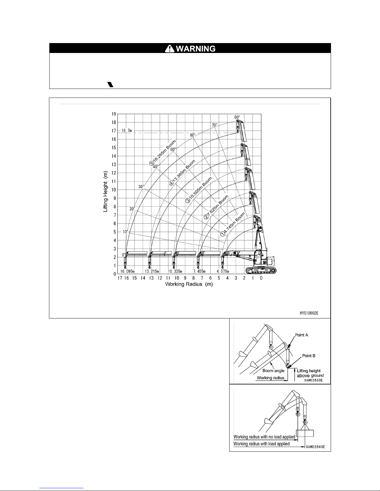
5.2 DIAGRAM OF WORKING RADIUS AND LIFTING HEIGHT
• The working radius/lifting height shows relationship between working radius, boom
angle and lifting height above ground of this machine with no load hoisted, and
deflection of the boom is not included.
• Stage "4" in the diagram of working radius and lifting height indicates that one half
portion of the " mark" is extruding from the 4th stage boom.
1. The point A in the figure at right indicates the boom angle
and point B the lifting height above ground.
The working radius of points A and B are the same.
2. The "diagram of working radius and lifting height" shows
the relationships between the working radius, boom
angle and lifting height at no load, allowing for no
deflection in the boom.
A deflection occurs in the boom when an object is hoisted,
which causes the working radius to widen slightly.
The rated total load decreases with increase in the
working radius. Actual crane operation requires the
planning of work, allowing for sufficient clearance more
than that provided in the diagram.

9
5.3 RATED TOTAL LOAD CHART
• Rated total load chart is based on level, hard ground.
• Values given in the rated total load chart are based on the working radius including
the deflection of boom under actual load.
•
When boom (3) is extended even for a minimal extent, perform the work within the
capacity indicated in the column of "boom (3)".
• When boom (4) is
extended even for a minimal extent, perform the work within the
capacity indicated in the column of "boom (4)".
• When more than one-half of the "
mark" of boom (4) is exposed from boom (3),
perform the work within the capacity indicated in the column of "boom (5)".
•
If working radius exceeds the value of Working Radius column in the chart by any
extent, work should be performed within the rated total load in the next column of
Working Radius.
• The value of a rated total load including the mass of hoisting accessories (hook: 90
kg (applicable for 2-fall and 4-fall wire rope) or 20 kg (dedicated for Single-fall hook
wire).

10
The rated total load chart provides the maximum loads that the crane is capable of hoisting
objects depending on boom length by working radius.

11
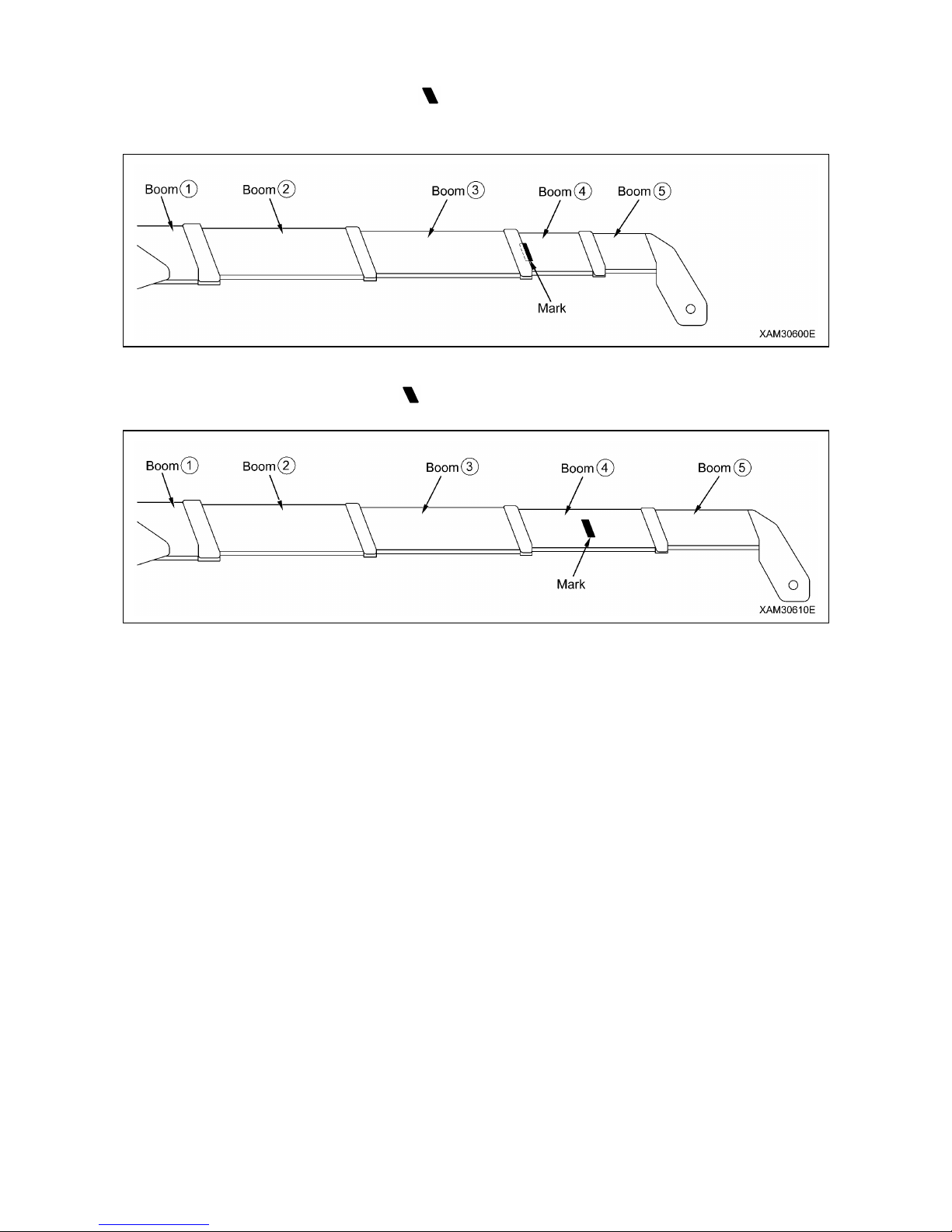
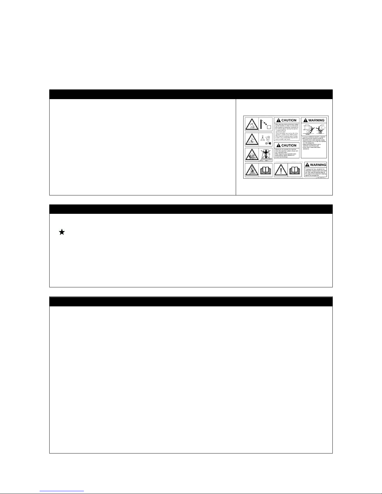
[1] BOOM LENGTH
In the Rated Total Load Chart, the "4.745 m boom (1)", "7.625 m boom (2)", "10.505 m boom
(3)", "13.385 m boom (4)" and "16.265 m boom (5)" given in columns on the top denote the
respective states of the following figures:
1. "4.745m boom (1)"
: All the booms are retracted.
2. "7.625 m boom (2)": Booms (3), (4) and (5) are retracted, while boom (2) alone is fully
extended.
If boom (2) is extended even to a small extent, perform the work in the capacity indicated in
this column.
3. "10.505 m boom (3)": (4) and (5) are retracted, while booms (2) and (3) are fully extended.
If boom (3) is extended even to a small extent, perform the work in the capacity indicated in
this column.
12
4. "13.385 m boom (4)": Booms (2) and (3) are fully extended, while booms (4) and (5) are
extended to an intermediate length ( mark) is exposed half way from boom (3).
If booms (4) and (5) are extended even to a small extent, perform the work in the capacity
indicated in this column.
5. "16.265 m boom (5)": All the booms are fully extended.
When more than one-half of the " mark" of boom (4) is exposed from boom (3), perform
the work within the capacity indicated in this column.

13
SAFETY
1. BASIC PRECAUTIONS 14
2. OPERATION RELATED PRECAUTIONS
20
3. TRANSPORT PRECAUTIONS
37
4. MAINTENANCE PRECAUTIONS 39
5. SAFETY LABEL LOCATIONS
48
All the safety precautions defined in this manual should
always be read and observed.
Failure to follow the safety precautions can cause
serious personal injury or death.
14
1. BASIC PRECAUTIONS
Incorrect operation and servicing may result in serious bodily accidents. Before starting
operation and servicing, read this manual and safety labels to observe their warnings and
precautions.
1.1 PRECAUTIONS BEFORE STARTING WORK
OBSERVE THE MANUAL AND SAFETY LABELS
• Read well and understand this manual as well as the safety
labels attached to various parts of this Machine. Attempt to
drive/operate without understanding fully may result in
wrong operation that may cause personal or equipment
accidents.
• Fully understand the proper use and inspection/maintenance
procedures, and perform the work safely.
•
Make sure this manual and the safety labels attached to
various parts of this Machine are legible all the time.
Whenever illegibility or loss occurs,
order us or our sales
service agency and put the safety label back to the original
location.
QUALIFICATION FOR OPERATION
• The operators of this machine are required to have adequate qualification.
Be sure to acquire the qualification before engage in the operation.
See "INTRODUCTION 4. QUALIFICATION FOR OPERATION
" for details of the
operational qualification.
•
When performing operations using this machine, be sure to carry the "mobile crane
operator's license" or the "completion certificate of skill training course for the operation of
light duty mobile cranes all the time. Also, when performing a slinging operation, always carry
the "completion certificate of skill training course for slinging operation".
• The operators are requested to receive education and training of the handling methods and
other subjects at the office, and obtain sufficient operation skills before work.
COMMIT TO SAFE OPERATION
•
Follow the instructions and signs given by the manager and work supervisor, and observe
safety first during work.
• Follow the crane work basics during work.
• Always make sure to carry out inspections before using this machine.
• Do not work under bad weather for instance strong wind, thunder or mist.
•
Do not drive under any condition when you are overtired, under the influence of alcohol or
after taking soporific drugs.
• Follow all of the workplace rules, safety regulations and operation method sequences during
operations and inspection/maintenance.
• Pay attention to surrounding conditions and pedestrians all the time during operation.
Whenever pedestrian approaches unwarily, abort the operation once, and t
ake a measure
such as issuing a warning.
•
When operating, be mentally prepared for unexpected situation so that you can take
measures immediately.
• Never attempt any use out of the capabilities and purposes described in this manual under
any circumstances.
• Observe the designated rated total load and work range when operating.
•
Never attempt inattentive driving, harsh driving or awkward operation under any
circumstances.
• Pull out the key when leaving the operator's seat.

15
1.2 PREPARING FOR SAFE OPERATION
PROVIDE SAFETY DEVICES FOR SURE
• Check to ensure that all guards, covers, mirrors and rear-view camera are attached properly.
Repair immediately if damaged.
• Understand how to use the safety devices well and use properly.
• Do not detach the safety devices under any circumstances. Keep control to achieve proper
function all the time.
• Improper use of the safety devices may lead to serious accidents.
• Do not rely too much on the safety devices whilst operating.
PREPARE FOR ABNORMALITY
• Make sure to carry out inspections and maintenances, and
make an effort to prevent accidents before happening.
• Whenever you feel an abnormality in the Machine, abort the
operation immediately, ensure safety and report to the
manager.
•
Assign in advance who takes which solution to prevent
secondary accident.
•
Never operate the Machine when fuel or hydraulic oil is
leaking from the Machine. Report
the manager about the
abnormality, and repair the leaking point of the
fuel/hydraulic oil completely before use.
The fuel for this Machine is diesel fuel. Be especially careful
for the presence of fuel leak.
•
Before leaving the Machine, lower the hoisted load to the
ground, stop the engine and pull out the starter key.
TEMPORARY STORAGE WHEN ABNORMALITY IS FOUND WITHIN MACHINE
In case the Machine is found with an abnormality and is
therefore stored temporarily waiting for service, apply
following measures to notify all persons in the office that "the
use is prohibited due to failure."
•
Put on warning tags on the operation lever and other
applicable parts.
Write clearly the information such as abnormality contents,
name and contact of the storage manager, and the term of
storage.
• Keep it immovable when parking by, for instance, putting the
blocks on the rubber tracks as pawls.
• Pull out the engine key and keep it with you.
WEAR PROTECTIVE EQUIPMENT AND CLOTHES SUITABLE FOR WORK
• Always put on a helmet, safety shoes and safety belt.
• Make sure to wear the necessary protective equipment
suitable for the relevant working condition.
• Do not wear loose garments or access
ories as these may
get caught on an operation lever or any protrusions which
could lead to unexpected movement of the Machine.
16
USE OF MACHINE THAT WAS RENTED OR PREVIOUSLY USED BY SOMEONE ELSE
Check the following subjects in writing before using any Machine that was rented or previously
used by someone else.
In addition, check the inspection record table for the maintenance conditions such as the
periodic inspections.
(1) Crane capacity
(2) Crane maintenance conditions
(3) Behaviors and disadvantages unique to the crane
(4) Other subjects that require attention while operating
(a) Operating condition of the brakes, clutch and others
(b) Presence/absence and lighting condition check-up of lighting and rotating lamps
(c) Operating condition of hook, winch, boom and others
ALWAYS KEEP THE MACHINE CLEAN
• If the Machine remains contaminated with soil, sand, oil and
grease, it may cause slipping,
tripping or tumbling when
getting on the Machine or maintenance servicing. Thus,
wipe off the soil, sand, oil and grease sticking to the
Machine to keep it clean all the time.
•
When washing the machine with water or cleaning it with
steam, prevent its electrical devices from being directly
splashed with water. Water entering the electrical system is
dangerous and will cause electrical devices to malfunction
resulting in faulty or improper operations. If
the Machine
malfunctions, it may behave unexpectedly, resulting in
serious injury.
CLEAN AND TIDY UP THE OPERATOR'S CABIN.
• Before getting in the cabin, wipe off shoe soles to remove dirt, oil and grease. Stepping on the
pedals with shoes that are contaminated with dirt, oil and grease may cause slipping,
resulting in an accident.
• Do not leave parts or tools in the operator's cabin. The parts and tools left in the cabin may
cause unexpected actions, resulting in serious injury.
• Do not attach suction cups to the window glass. It may work as a lens to cause fire.
• Do not bring any dangerous substances (such as combustibles and explosives) in the cabin.
• Do not use a mobile phone during running or operating. It may disturb operations, resulting in
serious injury.
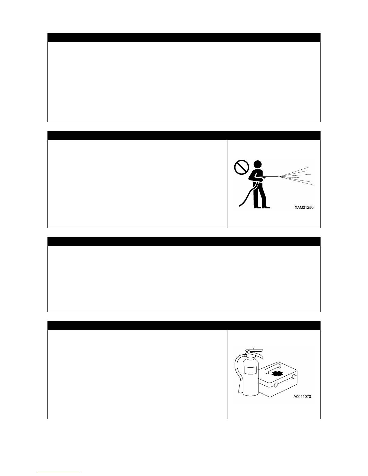
PROVISION OF FIRE EXTINGUISHER AND FIRST AID BOX
Always observe the following to prepare for injuries and fires.
• To prepare in case of fire, decide on a location and install a
fire extinguisher, and make sure to read the label for terms
of usage.
• Decide the location to store the first aid box. In addition,
inspect the first aid box periodically and replenish the
contents as necessary.
• Decide the measures to take upon an injury or fire accident.
• Decide how to contact the emergency address (for instance
the emergency physician, ambulance or fire department),
and put up the contact address at designated position so
that anyone can make the contact.
17
1.3 PRECAUTIONS FOR FIRE PREVENTION
WHAT TO DO IF A FIRE OCCURS
• Turn the starter switch OFF to stop the engine.
• Get out of the Machine by using a handrail and steps.
• Do not jump off the Machine. You may fall and get hurt.
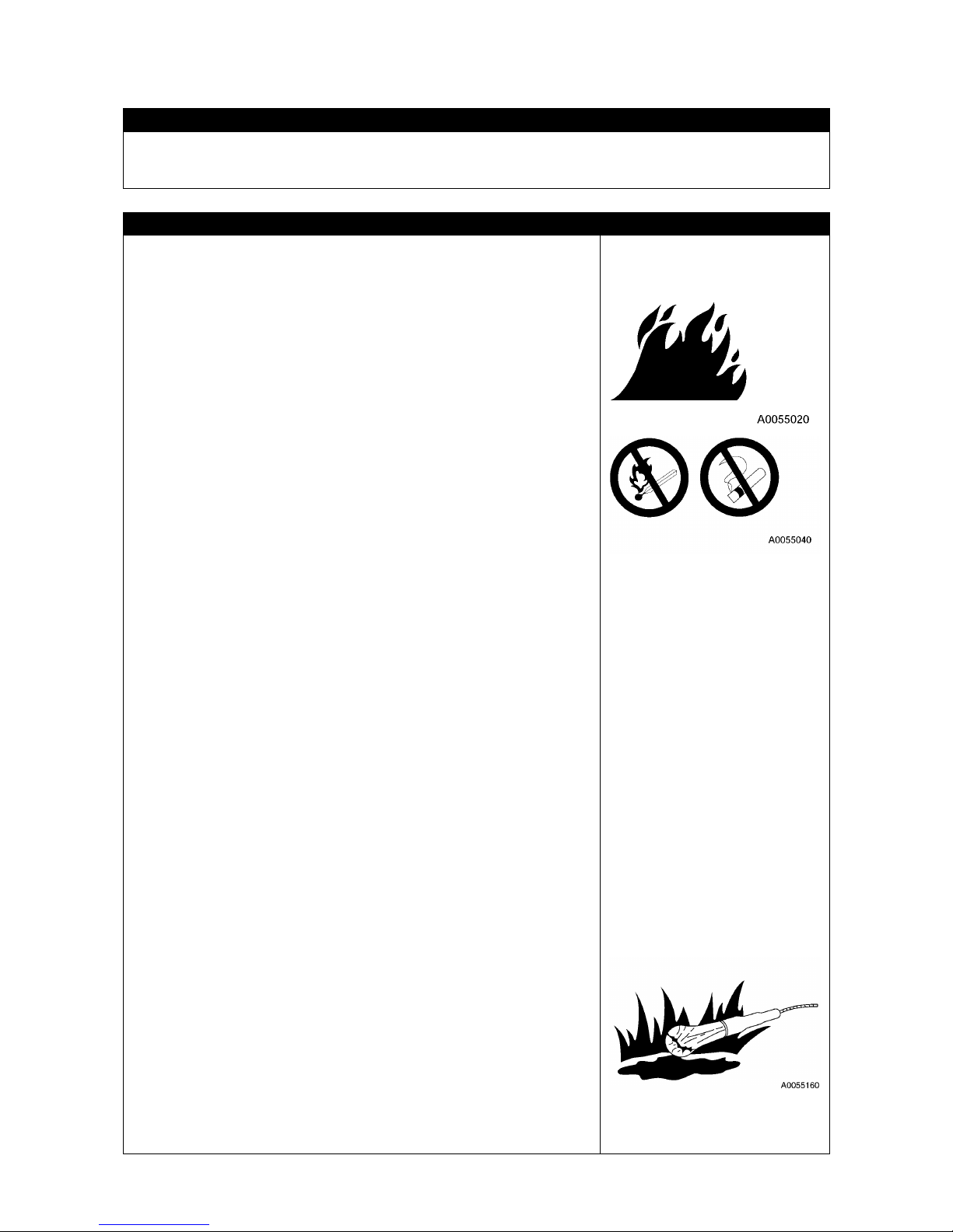
PREVENTING FIRE
• Fire caused by fuel, oil, anti-freezing fluid, or wind-washer
liquid
Attempt to let a fire approach the fuel, oil, anti-
freezing fluid, or
wind-washer liquid may result in catching fire. Strictly observe the
following.
• Do not smoke or use fire near the machine.
• Before refueling, be sure to stop the engine.
• Do not leave the site when replenishing the fuel or oil.
• Close and securely tighten the cap of fuel tank and hydraulic oil
tank.
• Do not spill fuel on an overheated surface and parts of electric
system.
• After refueling, cleanly wipe off spilt fuel and oil.
• Put rags and other combustibles smeared with oil in a safe
container and store it in a safe place.
• Use incombustible cleaning oil for the objects such as the
components, and do not use diesel fuel, petrol or anything else
that may catch fire.
• Do not weld or gas flame-cut piping and tubing containing
flammable solutions.
• Store the fuel and oil in a specified well-ventilated location and
prohibit public access.
• Before performing grinding or welding of the Machine, move
inflammables to a safe place.
• Fire due to deposition or adherence of combustibles.
• If any of such combustibles as dead leaves, chips, paper litters,
and charcoal dust is deposited on or sticking to the peripheral
area of engine exhaust manifold, muffler, battery or under-cover,
remove it.
• To prevent fire caused by bonfire sparks or other types of fire that
can be caught, remove such combustibles as dead leaves, chips,
paper litters, and charcoal dust that may be deposited on or
sticking to the peripheral area of cooling units (radiator and oil
cooler).
• Fire originating from electric wiring
Fire may be incurred by a short-circuit of electric system. Strictly
observe the following.
• Keep every connection of electric wiring clean and fix it securely.
• Check for any loosening or damage of electric wiring on a daily
basis, and if any loosened connector or wiring clamp is found,
retighten it and repair or replace any damaged electric wiring.
• Fire originating from piping
Check the clamps and cushions of each hose and tubing to ensure
that they are securely fixed.
Any loosening may give rise to
vibration during operation, rubbing with other parts to damage
hose, or spouting of high pressure oil, resulting in fire or physical
injury.
• Explosion triggered by lighting fixture
• When inspecting fuel, oil, battery electrolyte and coolant water,
use a lighting apparatus of explosion-proof specifications.
• When disconnecting power source from the Machine, follow the
instructions described in this manual.

18
1.4 CAUTIONS IN GETTING ON AND OFF THE MACHINE
USE A HANDRAIL AND STEPS WHEN GETTING ON AND OFF THE MACHINE
When getting on and off the Machine, be sure to observe the
following precautions in order to prevent physical accidents
such as slipping and falling or tumbling.
• Use the arrow-
marked handrails and steps shown in the
figure at the right when getting on and off the Machine.
•
When getting on and off the Machine, always face the
machine, allow the three parts of limbs (both feet and a
hand, or a foot and both hands) to come into contact with the
hand rails and steps to hold your body.
• Before getting on and off the Machine, check the handrails
and steps for any damage or loosening, and for any oil or dirt
sticking to the Machine surface.
When oil or dirt is
deposited, do not fail to thoroughly clean it so that the
surface is not slippery.
Repair any damage and retighten
any loosened bolt.
•
Do not grasp operating levers and locking levers when
getting on and off the Machine.
• Never
step on the engine hood and cover that are not
treated with anti-skidding coating.
• Do not get on or off the machine while holding a tool in hand.
• Do not jump on or off the Machine. Also, do not get on or off
the moving Machine.
• Even if the Machine
unexpectedly begins to move
unmanned, never jump on it to stop it.
CAUTIONS IN STANDING UP FROM THE OPERATOR'S SEAT OR LEAVING THE
MACHIHNE
• Before standing up from the operator's seat for opening or
closing the front or ceiling window, detaching or attaching
the lower window, or adjusting the operator's seat, be sure
to retract the crane and set the lock lever (1) to "LOCK"
position (L) and stop the engine.
Inadvertently touching operating levers may cause the
machine to suddenly move and invite serious injury.
• When leaving the Machine, be sure to retract the crane, set
the lock lever (1) to "LOCK" position (L), and stop the
engine. Also apply every lock, be sure to bring the key back,
and store it in a specified place.
EMERGENCY EXIT OF THE OPERATOR'S CABIN
•
If by any chance, the cabin door fails to open, use the
provided hammer to break the window glass and escape
through the opening.
•
Before getting out, remove the broken fragments of glass
from the window frame to avoid getting hurt.
Also, watch
your step not to slip on broken fragments of glass.

19
1.5 OTHER PRECAUTIONS
CAUTION AGAINST BEING CAUGHT
In the periphery of the upper slewing body and crane unit, the
clearance varies with the motion of derricking cylinder and
winch. If being caught in it, serious injury may occur.
Keep persons away from all rotating and telescoping
sections.
Never allow your body or part of it to get in the following gaps:
• Between the boom and the upper slewing body
• Between the boom and the derricking cylinder
• Between winch drum and wire rope
• Between each sheave and wire rope
REMODELING THE MACHINE IS PROHIBITED
Do not remodel the Machine without our written consent under any circumstances.
Particularly, partial welding of the Machine may damage the safety device.
The remodeling raises a safety issue, so consult us or our sales service agency beforehand.
We cann
ot be held responsible for any personal injury or failure caused by remodeling the
Machine that was performed without consulting us.
CAUTIONS ON ATTACHMENTS AND OPTIONAL UNITS
• We cannot be held responsible for any personal injury, failures or property
damage of
attachments and optional units that are not recognized by us.
• Installing an attachment or optional units may give rise to safety and legal issues, and thus
the customer is kindly requested to consult with us or our sales service agency beforehand.
• Depending on the combination of attachments and optional units they may cause interference
with operating cabin and machine parts. Interference with the Machine during operation may
cause serious injury. Check to ensure that the attachments and
optional units to be used
would interfere with the Machine, and use them within the interference-free range.
•
Never fail to read the descriptions on the attachments and optional units given in the
instruction manual of the installed attachment as well as this manual.
CAUTIONS ON THE CABIN GLASS
• If the cabin glass is broken, immediately stop operation and have it repaired.
• When the ceiling window is scarred, the visibility is spoiled and probability of breakage rises.
Replace the scarred ceiling window glass at an early stage. Leaving the scars increases the
risk of breakage by any object falling onto the ceiling window, resulting in injury.
CAUTIONS ON RUNNING THE ENGINE INDOORS
To prevent the risk of petrol
poisoning from starting the
engine/handling fuel and cleaning oil/painting indoors or at a
location with bad ventilation, open the windows and exit
doors.
If the ventilation is insufficient even after opening the
windows and exit doors, set up a ventilation fan.

20
2. OPERATION RELATED PRECAUTIONS
2.1 PRECAUTIONS ON WORK SITE
SURVEY AND SAFETY ASSURANCE OF WORK SITE
A number of risks that may cause serious injury are imbedded in a work site. Before starting
work, check the following matters beforehand to ensure that no danger is present at the
worksite:
• When working near straw-
thatched roofs, dead leaves or dead grass, beware of those
fire-catching object.
• Investigate the ground and road surface condition of the worksite and decide the best working
method. At a site where risk of landslide or rock fall exists, do not operate the Machine.
• Flatten the inclination of the worksite before starting work.
• When working over the roadway, enforc
e "keep out" by, for instance, assigning guides or
surrounding the site by barriers, and ensure the safety of the traffic vehicles and pedestrians.
•
Enforce "keep out" to prevent people from entering the worksite and apply measures to
prevent people from approaching. Attempt
to approach the moving Machine may result in
pinching or hard collision by contact, and may result in serious accidents and deaths.
• When running on a shallow bottom stream or weak ground, examine the water depth, water
flow velocity
as well as ground condition and land features in advance in order to avoid
hazardous place for traveling and operation.
•
The ground of a zone adjacent to a cliff, road shoulder, and deep ditch is likely to be
loosened, and thus it should be avoided for running and performing operation. The ground in
such a zone may be collapsed by the mass and/or vibration of the Machine, which may trip or
fall. Be especially careful after rain, use of dynamite, or earthquakes, as the ground will be
unstable.
• The ground of an area near an earth fill or in the vicinity of a dug gutter may be collapsed by
the mass and/or vibration of the Machine, resulting in the trip or fall of the Machine. Before
starting operation, take necessary measures to make the ground intact and safe.
SECURING VIEWS
This Machine is equipped with such devices as mirror and rear view camera that provide
improved views. Though some areas can hardly viewed from the operator's seat, and thus be
cautious in operation.
Running and operating in places
with poor visibility prevent the operator from detecting
hazards around the Machine and recognizing work site status, and thus may cause serious
injury.
When running and operating the Machine in place with poor visibility, strictly observe the
following:
• If adequate view cannot be secured, deploy personnel as a marshaller as required. In that
case, limit the number of signaling marshaller to one person.
• In a dark place, turn on the working light and head lamps equipped with the Machine, and use
additional lighting devices as required to light up the work site.
• When visibility is spoiled by fog, snow, rain or sand dust, stop the operation.
• If the mirrors mounted on the Machine are contaminated, clean them and adjust the field of
view to secure visibility.
•
If the rear view camera is contaminated, clean the lens to secure clear vision around the
periphery.
RECOGNIZING THE SIGNAL OF MARSHALLERS AND STREET SIGNS
• To ensure the identification of weak road shoulder and ground, install sign boards. Further,
for a place with poor visibility, appoint marshaller as required. In that case, limit the number
of signaling marshaller to one person.
The operator should pay attention to sign boards and follow the marshaller's instructions.
• All the pe
rsonnel involved should understand the meaning of every signal, sign and sign
board.

21
Voltage of
Electrical Cable
Minimum Safe
Distance
Low voltage
(Distribution
line)
100/200V
2m
6,600V 2m
Special
voltage
(Transmission
line)
22,000V
3m
66,000V
4m
154,000V
5m
187,000V
6m
275,000V
7m
500,000V
11m
BEWARE OF ELECTRICAL CABLE ABOVE
• Do not let the Machine touch the electrical cables above.
High voltage cables may also inflict electrical shock by close
proximity.
• Slinging operators are likely to suffer electrical shocks.
Always observe the following to prevent accidents.
• If the boom or the wire ropes may contact an electrical
cable in the workplace, consult the electricity company and
make sure that the measures (for instance placement of a
guard personnel or application of wrap tubes and warning
tags to the electrical cable) stipulated by the related
regulations are taken before starting work.
• Put on rubber soled shoes and rubber gloves, and be
careful that the body parts unprotected by rubber or other
insulation do not contact the wire rope or the Machine
frame.
• Place a guide and let him/her watch so that the boom, wire
rope or Machine frame does not go near the electrical
cable too much.
Before
doing so, decide the emergency signs and other
necessities.
• Ask the electricity company for the voltage in the electrical
cables at the worksite.
• Secure the separation (safe distance) shown in the
following table between the boom/Machine frame and
electrical cables.
MEASURES WHEN CHARGE ACCIDENT OCCURS
If a charge accident occurs, react calmly and take measures in the following procedure.
1. Report
Immediately report to the electricity company or related management company, and receive
instructions for the power transmission stop, emergency procedures and related matters.
2. Evacuation of related personnel from vicinity of Machine
Evacuate all personnel, including workers, from the vicinity of the machine to prevent secondary
disasters.
Personnel who suffered elec
trical shock by holding a sling rope, guide rope or other conductor
when the Machine was charged should evacuate by his/her own effort.
Do not try to help personnel affected by electric shock.
Otherwise, secondary electrical shock
accident will occur.
3. Emergency procedure
In the case of personnel receiving an electric shock due to the machine being electrically charged,
do the following:
(1) If the machine is operational, immediately move it to a safe location away from the cause of the
electrical charge. Take care not to break or disrupt the distribution power cable.
(2)
Move the machine to a safe location, and after making sure the machine is not electrically
charged, take the affected personnel to the hospital.
4. Measure after accident
After the accident, do not reuse as is.
Such attempt may cause unexpected accidents and
enhances failures.
Ask us or our sales service agency for repair.

22
CAUTIONS WHEN OPERATING CRANE IN LOCATION WITH HIGH OUTPUT
MICROWAVE EMISSION
Operating the crane near high output microwave emission equipment such as a radar or
TV/radio broadcast antenna causes the crane construction to be exposed to the microwave
and generates induced current, therefore is very dangerous. In addition, the mechatronics may
become haywire.
Establish grounding between the Machine frame and the ground when working in such
location. In addition, slinging operators are requested to wear rubber boots and rubber gloves
since risk of electrical shock by contacting parts such as the hook or wire exists.
BEWARE OF ASBESTOS DUST
Inhalation of asbestos dust may result in lung cancer. This
Machine does not contain asbestos, but asbestos may be
found in the wall, ceiling or other construction locations within
the worksite of this Machine.
In addition, be careful of the
following when working with a material that may contain
asbestos.
•
Put on designated dust free mask and/or other protection
equipment where necessary.
• Do not use compressed air for cleaning.
• Spray water
when cleaning to prevent airborne asbestos
dust.
•
Always work at windward location when operating the
Machine at a site that may contain asbestos dust.
• Do not allow unauthorized personnel to approach the work
site.
• Strictly observe the assigned rules
related to the worksite
and environmental standard.

23
2.2 CAUTIONS WHEN STARTING ENGINE
PAY ATTENTION TO WARNING SIGNS
When warning sign "DANGER. DO NOT OPERATE!" is put
up, the Machine is being inspected and under maintenance.
Do
not start the engine and refrain from touching operating
levers. Disregarding the warning sign to operate the Machine
may give rise to the danger of involving the preparing
personnel into the rotating parts or movable parts of the
Machine, resulting in serious injury.
INSPECTING AND ADJUSTING BEFORE STARTING ENGINE
Before starting engine at the beginning of the day, perform items under "Operations 3.1
PRE-OPERATION INSPECTION" and conduct the following inspections. Omitting these
inspections may cause serious bodily accidents.
• Never fail to execute the inspection before starting work.
• Remove the contamination on the window glass surface to secure good view.
• Clean the lens surface of head lamps and working lights and ensure that they are properly lit.
• Check the coolant water level, fuel level, engine oil pan level, air cleaner for any clogging and
electric wiring for any damage.
• Adjust the operator's seat to the operator's posture for easy work. Also, check seat belts and
their mounting fixtures for any damage or abrasion.
Refer to the descriptions under "OPERATION 3.1.2 [11] ADJUSTING THE OPERATOR'S SEAT".
•
Adjust the mirrors to the best position for commanding a good view of rear scene and the
drum from the driver's seat.
Refer to the descriptions under "OPERATION 3.1.2 [12] ADJUSTMENT OF MIRRORS ".
• Adjust the rear view camera to the best angle to check the image on the monitor display and
command a good view of the scene in the rear.
Refer to the descriptions under "OPERATION 3.1.2 [14] ANGLE ADJUSTMENT OF REAR
VIEW CAMERA ".
• Check pedals for any dirt or foreign matter deposited on their movable parts and ensure that
they can function satisfactorily.
• Check instruments to ensure that they function properly and each of the operating levers is in
its neutral position.
Always repair if any result of the above is faulty.
CAUTIONS BEFORE STARTING ENGINE
• Make sure nobody is on or under the Machine and in its
vicinity and nobody or no hazard is found within the boom
slewing range.
• Do not allow anyone other than the operator to get on the
Machine.
•
Start the engine only when the operator is sitting on the
operator's seat.
•
Check to ensure that each of the operating levers is in its
neutral position.
• Check to ensure that lock lever (1) is in the "LOCK" position (L).
• Honk the horn for warning before starting the engine.
• Do not start the engine by short-circuiting the starter circuit.
This may cause a fire.
24
CAUTIONS UNDER COLD WEATHER
•
Remove snow from and defrost the surface of the slewing
gear, boom and around winch, and ensure that their
movements before starting work.
• Before starting the engine, ensure that the automatic glow
lamp goes off.
• Operating the Machine without sufficient engine warm-up
causes slow response of the Machine to the operation of
levers and pedals, and thus unexpected motion may occur
against the operator's will. Do not fail to execute the engine
warm-up. The engine requires an adequate warm-
up time
especially in cold climates.
• When the battery electrolyte is frozen, do not recharge the
battery or start the engine with another power source. Such
act may cause the battery to catch fire or explode. Defreeze
the battery electrolyte and check for fluid leak before
re-
charging or starting the engine by using another power
supply.
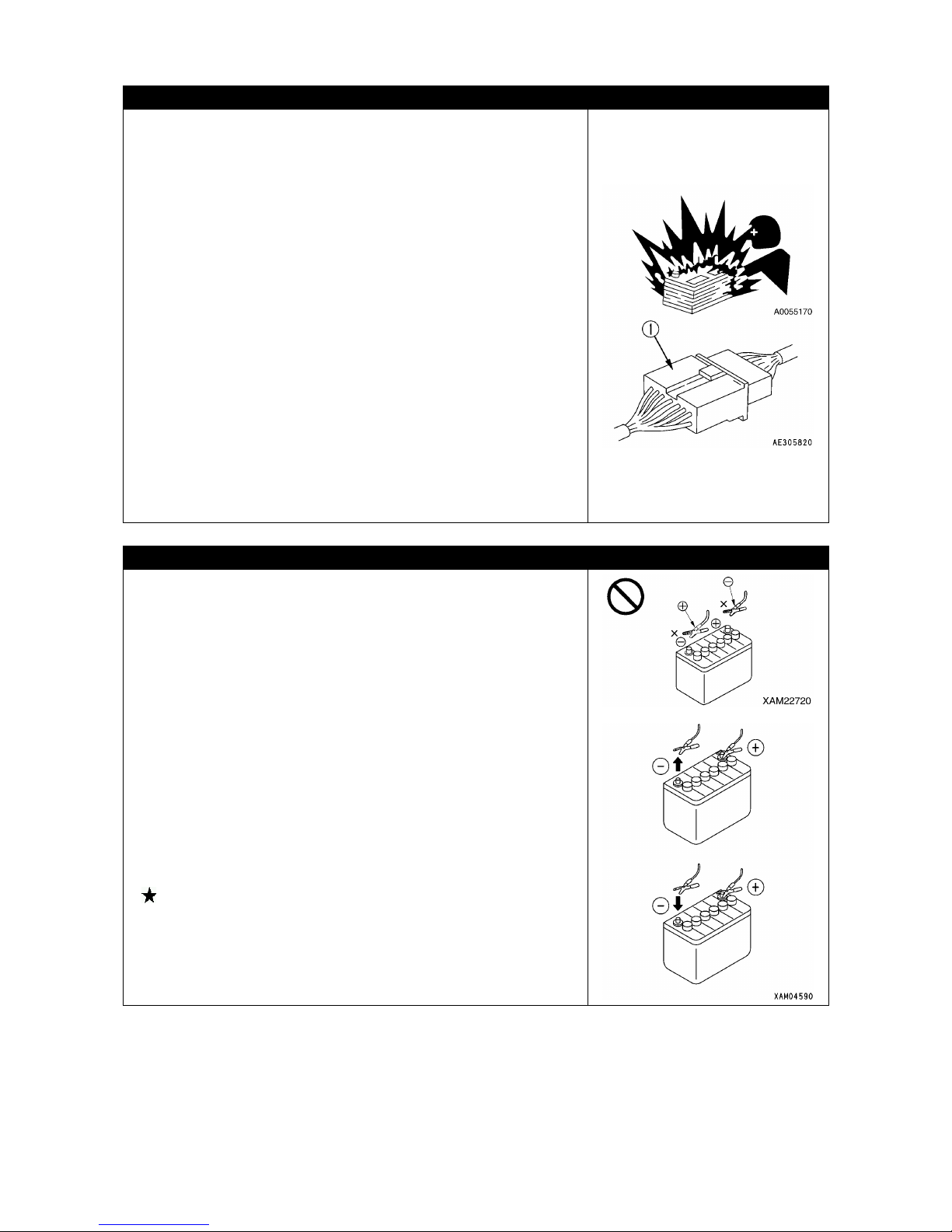
•
After end of the work, wipe off and put on a cover if
substances such as condensation, snow or mud are stuck to
the wire harness, connector(1), switches, sensors or similar
part. If the infiltrated condensation and/or similar substance
freeze, the Machine may operate improperly upon the next
use and cause unexpected accidents.
CAUTIONS WHEN STARTING UP USING BOOSTER CABLE
Wrong booster cable connection method may result in fire, so
always observe the following.
•
When using a booster cable for engine start, perform the
2-
person operation by one person on the operator's seat
and another on the battery side.
• When starting the engine using other Machine, be careful to
prevent contact between the normal Machine and broken
Machine.
• Keep the starter switch key of both the normal Machine and
the broken Machine in "OFF
" position when the booster
cable is connected.
• Do not connect to wrong side [connecting (+) to (-), (-) to (+)]
when connecting the booster cable.
• Start connecting from (+)
terminal first, but start
disconnecting from (-) terminal (ground) first.
• Connect the ground to the (-) terminal of the broken Machine
when connecting the ground as the last procedure.
Refer to the description under “OPERATION 8.3.4
STARTING ENGINE WITH BOOSTER CABLE ".
•
Avoid contact between clips of the booster cable, and
contact between a clip and the Machine when disconnecting
the booster cable.
25
2.3 PRECAUTIONS FOR STARTING CARRIER AND OPERATING
CRANE
INSPECTION BEFORE STARTING OPERATION
Omitting the inspections after starting the engine results in delay to discover the Machine
abnormalities, and may result in accidents and Machine damages.
Inspection should be carried out in a clear area. No unauthorized persons should be able to
approach the Machine.
• Ensure that motion of the Machine coincides with the indication of pattern card.
• Check the operation status of devices, running status of the Machine, winch wind up/down,
boom derricking, and crane operating status such as telescoping and slewing.
• Inspect the sound, vibration, heat and odour of the Machine, and check for instrument errors,
air leaks, oil leaks, fuel leaks, water leaks and other bad factors. Be especially careful for the
fuel leak.
• Always repair broken part whenever an abnormality is found.
Attempt to use without servicing may result in unexpected accidents and/or Machine
failures.
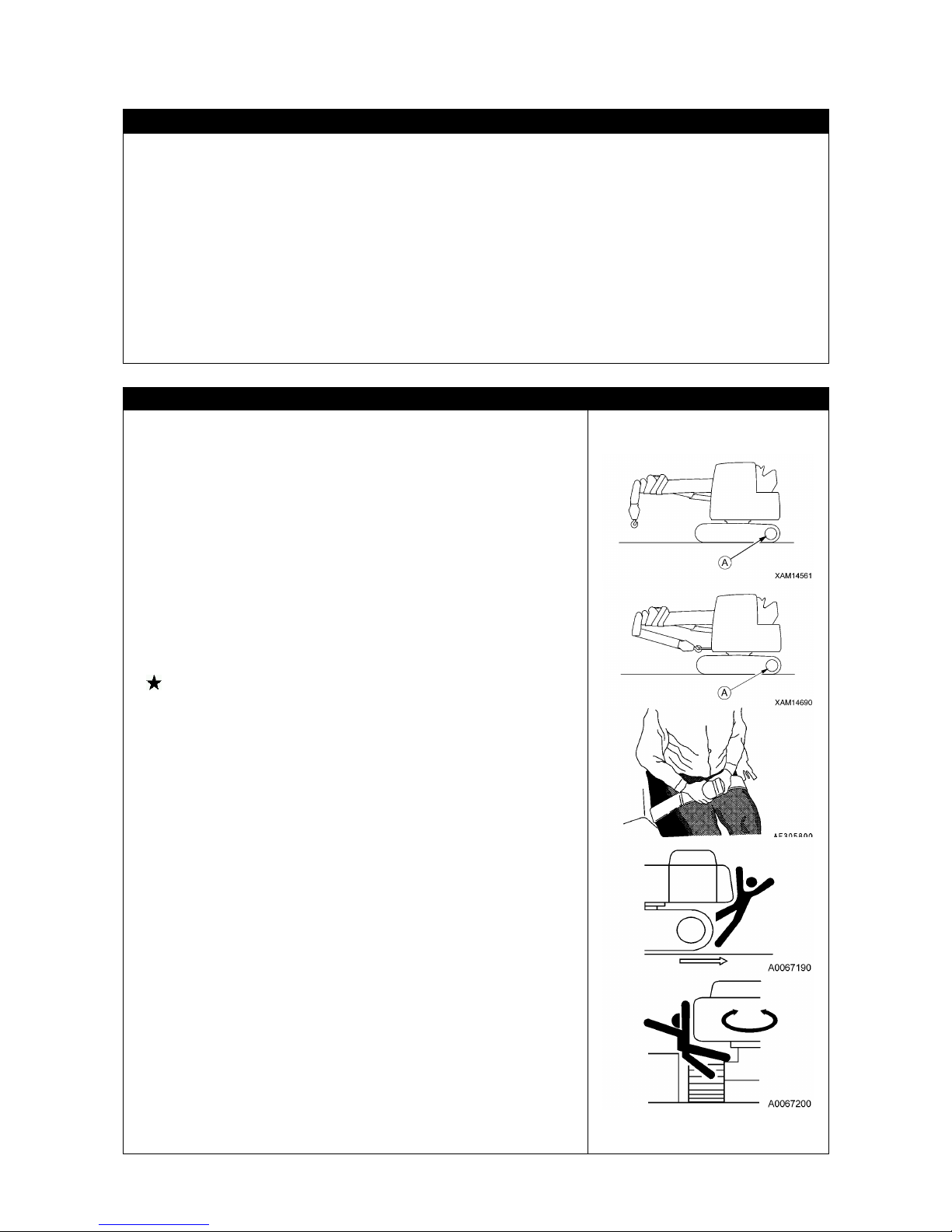
CAUTIONS ON MACHINE FORWARDING/REVERSING AND SLEWING
Always observe the following to prevent serious injuries and
accidental death when moving the Machine.
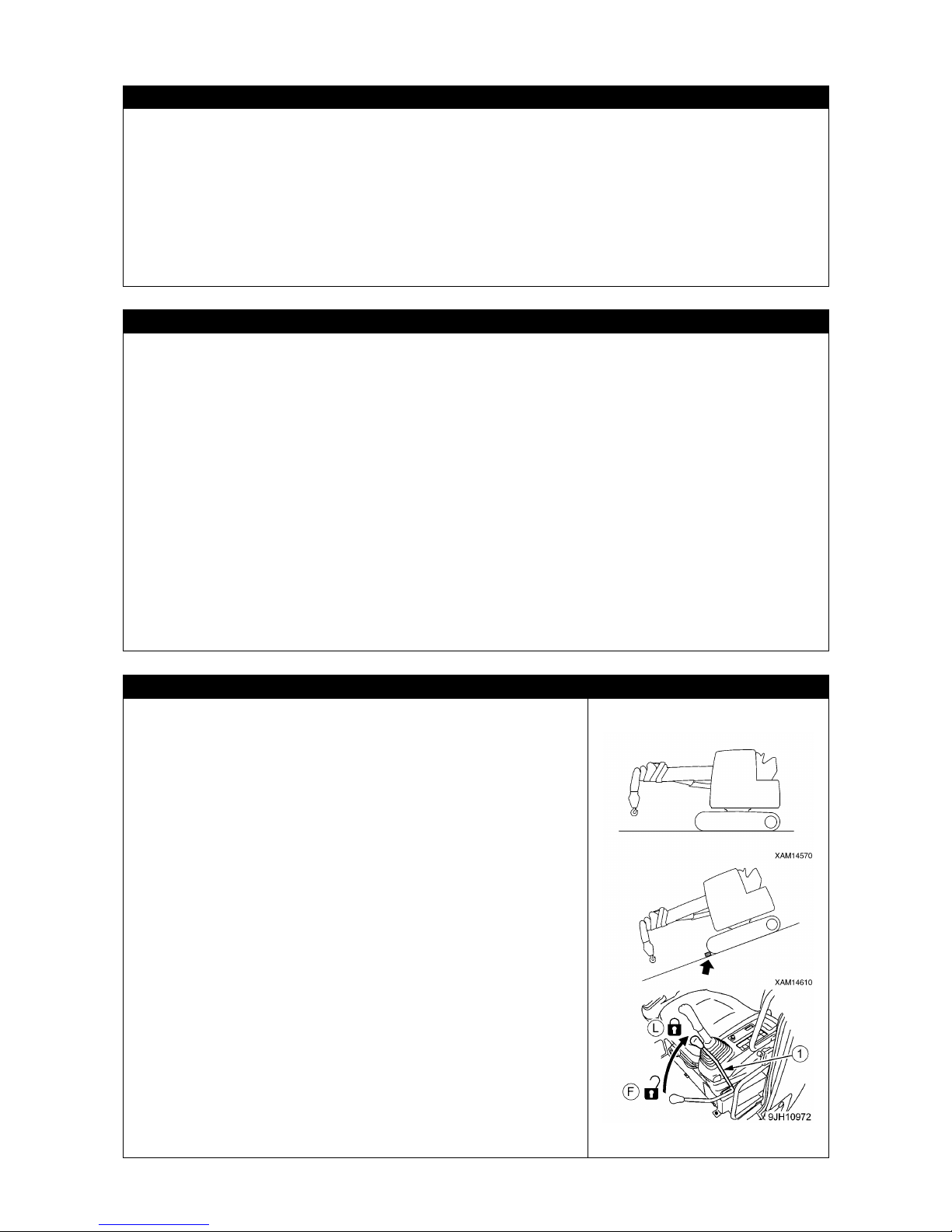
• Set the Machine to the travelling posture in the right figure.
Do not allow the machine to travel without retracting the hook
block.
• Before traveling, move the sprocket to the rear of the machine.
Leaving the sprocket in front of the Machine causes the
direction of actual running to be in reverse of the running
lever, and thus the Machine may move toward undesired
direction, resulting in serious bodily accidents.
• Make sure the boom is fully lowered and retracted.
• When moving the Machine for a short distance, fix the hook
block in the retracting position at the tip of the boom. When
moving it for a long distance, fix the hook block to the hook
holder at the front end of the upper slewing body.
Refer to the descriptions under "OPERATION 3.7 MACHINE
TRAVELLING POSTURE ".
•
Keep the door and window of operator's cabin always fixed
either open or closed. Nevertheless, when being in such an area
where any flying object may come into the cabin, be sure to
keep them closed.
• If any person is staying around the Machine, they may come into
contact of the Machine or may be caught by it, resulting in a
serious bodily accident.
Before starting to move, strictly observe the following:
• Operate the Machine only when the operator is sitting on the
operator's seat.
• Do not fail to wear the seat belt. Otherwise, the operator may
be forced to jump out of the cabin because of an emergency
braking, resulting in injury.
• Make sure to check around again so that no one or no object
is in the vicinity before starting to move.
•
Before starting to move, be sure to honk the horn to warn
people around the Machine.
• When ru
nning, check to ensure that the traveling alarm
sounds normally.
• When there is a view-
obstructing range in the rear of the
Machine, appoint a marshaller to ensure that no contact
accident will occur and slew the machine by paying adequate
attention.
Even if the Machine is equipped with mirrors and the rear view
camera, be sure to appoint a marshaller.

26
CAUTIONS WHEN TRAVELLING
Always observe the following to prevent serious injuries and
accidental death when moving the Machine.
• Set the Machine to the travelling posture in the right figure.
Refer to the preceding subsection "CAUTIONS ON
MACHINE FORWARDING/REVERSING AND SLEWING".
•
Do not attempt looking sideways or other dangerous act
when driving.
• Do not over speed, start moving/stopping/slewing
suddenly, or meander since such acts are dangerous.
• During traveling, keep an adequate distance from persons,
structures and other machines to prevent any contact
accident.
• When running on a rough terrain or a steep slope, be sure
to turn the automatic deceleration switch OFF (for
cancellation).
Operating the Machine while the switch is
turned ON raises the engine revolution speed, and the
vehicle speed may suddenly be increased.
• Avoid moving over any obstacle. Travel as slow
ly as
possible when moving over an obstacle for unavoidable
reason. Since the Machine tends to tumble more easily in
the lateral direction rather than in the longitudinal direction,
never attempt to move over an obstacle that will cause the
Machine to inclined to leftward or rightward.
• When traveling on a rough terrain, keep the vehicle speed
at low level to avoid tumbling and also avoid any abrupt
change of traveling direction. Such may cause the Machine
to lose balance or damage the Machine or nearby object.
•
When running on a bridge or crossing over a structure,
check the withstand strength of the bridge or viaduct
against the Machine mass beforehand.
Further, when
running on a public road, check with the competent
authorities and follow their instructions.
•
When operating the Machine in a place where machine
height is restricted such as in a tunnel, in a building, under
an overpass or cables, pay close attention to prevent the
Machine and crane from coming into contact of those
objects and operate the Machine slowly.
27
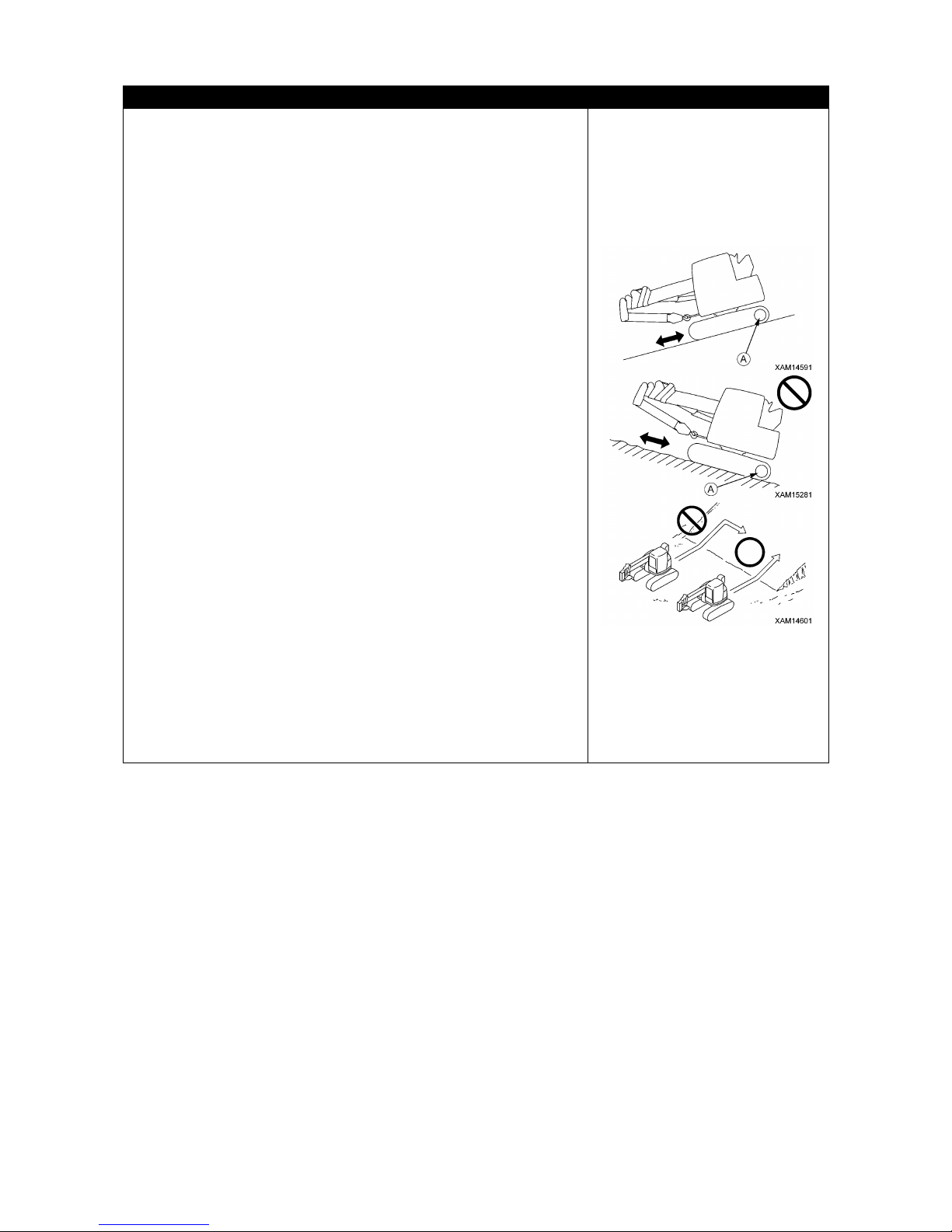
BE CAREFUL WHEN TRAVELLING OVER SLOPE
Always observe the following to prevent serious injuries and
death accidents when travelling over a slope for unavoidable
reason.
• When running on a slope, be sure to store the hook block in
the hook holder at the front end of the upper slewing body
to form a running posture.Any simplified fixation of the hook
at the tip of boom gives rise to the risk of loosening during
running.
Refer to the descriptions under "OPERATION 3.7
MACHINE TRAVELLING POSTURE
" for the travelling
posture of the Machine.
•
When running on a slope having an inclination of 10
degrees or more, climb the slope in the reverse direction
and run downhill in the forward direction.Thus, always
allow the Machine front to face the valley when running on
a slope.Climbing the slope in the forward direction and
going downhill in the reverse direction cause the Machine
to be unstable, giving rise to the risk of tumbling or lateral
skidding.
• When running on an inclined terrain, d
irect the machine
perpendicular to the slope and never change the direction
on the slope or drive parallel to the slope.
Practice safe travelling by for instance lowering to the plain
land and divert.
•
Always keep such condition during running that the
Ma
chine can stop any time when it slips or becomes
unstable.
• When running downhill, lower the engine revolution and set
the running lever close to the neutral position and run in a
low speed.
• When running on a ground covered with grass and leaves or
on a wet steel plate, keep the speed to minimal. If the
ground in such condition is inclined only slightly, it is
extremely slippery.
• If the engine comes to a sudden stop, immediately return
each operating lever to its neutral position, and then restart
it.
28
BE CAREFUL OF TRIPPING ON UNSTABLE GROUND
Always observe the following to prevent serious injuries and death accidents when travelling
over an unstable ground for unavoidable reasons.
• Do not enter soft ground area. The machine may get stuck.
• The ground near cliff, roadside and deep gully is unstable, so avoid going near such ground
as much as possible.
The Machine may trip or fall when the ground loosens due to mass and/or vibration of the
Machine. Be especially careful after rain, use of dynamite, or earthquakes, as the ground will
be unstable.
• Avoid going near the earth fills or vicinity of dug gutter that are instable.
Crumbles caused by mass and/or vibration of the Machine may cause the Machine to tilt.
CAUTIONS WHEN TRAVELLING SNOW COVERED OR FROZEN GROUND
Always observe the following to prevent serious injuries and death accidents when travelling
over snow covered ground or frozen road for unavoidable reason.
• The snow covered grounds and frozen roads cause slips even when the inclination is small,
so decrease the speed when travelling and avoid sudden starting/stopping/slewing. Uphill
and downhill are especially likely to cause slips and thus dangerous.
• Frozen ground tends to be weak with the increase of atmospheric temperatu
re, and may
cause the Machine to tumble or obstruct the operator to get off. Be very careful.
• Moving into an area covered with deep snow may cause the Machine to tumble or dive into
the snow. Be cautious of erroneously deviating outward from the road shoulder or driving into
a snow drift.
• Running on a snowbound site may encounter the risk of tumbling or collision because of an
invisible road shoulder or snow-covered installations. Be very careful.
• Refrain from directly touching metal surface with your
hands or fingers in cold and harsh
weather conditions.
Touching metal surface may result in skin freezing to the metal surface.
• Remove snow and/or ice laid on the Machine that causes the safety nameplates to be hard
to read. Be especially careful to securely remove those that are on the boom and thus may
fall.
CAUTIONS WHEN PARKING
• For parking, select an area with flat and solid ground.
• For parking, select an area without the risk of landslide, rock fall
and water submersion.
• When parking, set
the Machine to the "traveling posture" as
shown in the figure at the right.
• Make sure the boom is fully lowered and retracted.
• When parking the Machine for a short period of time, fix the
hook block in the retracting position at the tip of the boom.
When parking for a long time, fix the hook block in the hook
holder at the front end of the upper slewing body.
•
When inevitably stopping the machine on an inclined area,
strictly observe the following:
• Make sure the boom is fully lowered and retracted.
• When parking the Machine for a short period of time, fix the
hook block in the retracting position at the tip of the boom.
When parking for a long time, fix the hook block in the hook
holder at the front end of the upper slewing body.
• Direct the boom toward the valley.
• To keep the Machine immobile, apply a block as a chock.
• When leaving the Machine, strictly observe the following:
•
Set the lock lever (1) to "LOCK" position (L), and stop the
engine.
• Be sure to close the cabin door, and apply every lock. Do not
fail to remove the starter key to prevent the Machine from
operated by other personnel without approval, and keep it in a
specified place.

29
2.4 CAUTIONS DURING CRANE OPERATION
INSPECTION BEFORE STARTING WORK
Check that the safety devices and crane operate properly.
•
Operate each of the operation levers, pedals and switches under no load, and check that
operations take place without any abnormality.
Repair immediately if any abnormality exists.
• Check such safety devices as moment
limiter (overload prevention device), over winding
prevention device and over-
unwinding prevention device to ensure that they function
normally.
CAUTIONS WHEN SETTING MOMENT LIMITER
• In the moment limiter, the moment is calculated on the assumption that the machine is
placed horizontally.
If crane work is performed without the machine being placed horizontally, no forecast or
warning is issued even when the rated total load is approached.
Never fail to check the inclination of the Machine by using the level on monitor.
•
When using the moment limiter, check to ensure that the indicators of boom angle, boom
length and actual load are interlocked with the crane motion to give correct values. If the
crane is used with no correct indication given, correct measurement results cannot be
obtained, causing serious physical injury due to tumbling or damage of the machine.
• When using the moment limiter, be sure to check that the setting of wire falls of the moment
limiter matches the wire falls of the crane. If the number of falls does not match each other,
either alter the setting of wire fall count moment limiter or alter that of crane so that the count
matches each other. Using the moment limiter wi
thout matching its number of falls may
cause the breakage of wire rope, resulting in a serious bodily accident.
• Do not change the setting carelessly during measurement with the moment limiter.
Otherwise, correct measurement results cannot be obtained, causing serious physical injury
due to tumbling or damage of the machine.
CAUTIONS FOR SELECTING A PLACE TO INSTALL
Always place the Machine on a level, stable and solid ground.
It is dangerous to install on any of the following places:
• Simple asphalt pavement
• Thin concrete pavement
• Flagstone pavement
• Areas where under the pavement surface is hollow due to water erosion and the top soil
appears to be hard but soft in the ground
• Soft ground near a road shoulder or dug hole
• Slope
30
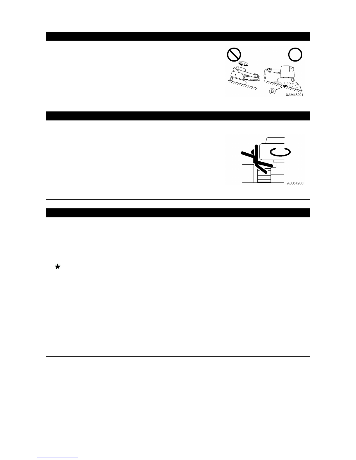
CAUTIONS WHEN WORKING ON A SLOPE
When inevitably perform operation on a slope, provide an
earth fill (B) to create a horizontal, solid and strong footing for
installing the Machine in order to prevent it from tumbling.
Attempting a diagonal hoisting without
ensuring the
horizontal installation of the Machine not only disturbs the
normal functioning of the moment limiter (overload prevention
device), but also affect the Machine with an unexpected
force, resulting in tumbling or damage of the Machine.
FOLLOW INSTRUCTIONS AND SIGNS WHEN WORKING
• When operating the crane, appoint a work supervisor and
mutual signs beforehand, and follow the work supervisor
and signs during operation.
•
When operating at a driver's blind spot, especially follow
the instr
uctions and signs of the work supervisor and
operate with caution.
•
When operating the crane, there is a danger of colliding
with slewing boom and upper slewing body and of the gaps
between movable parts of the derrick cylinder that may
catch body parts such as your arm or finger.
The operator is requested to make sure no one is within the
working radius of the crane before operating.
CAUTIONS UNDER COLD WEATHER
• Remove snow from and defrost the surface of the slewing gear, boom and around winch, and
ensure that their movements before starting work.
• Check the brake of winch to ensure that it works properly.
• Operating the Machine without sufficient engine warm-
up causes slow response of the
Machine to the operation of levers and pedals, and thus unexpected motion may occur
against the operator's will. Do not fail to execute the engine warm-up. The engine requires an
adequate warm-up time especially in cold climates.
For details of engine warm-up, refer to "OPERATION 3.4.1 WARM-UP OPERATIONS FOR
ENGINE" and "OPERATION 3.4.2 WARM-
UP OPERATIONS FOR HYDRAULIC
EQUIPMENT".
• Avoid revving up the engine immediately after starting it.
• Deposited snow within the crane operation range may cause tumbling of unloaded objects or
catching feet of operators around the Machine. First
remove snow before starting a crane
operation.
• In cold weather conditions, check that the
load before being hoisted is not frozen to the
ground or other substance. Attempt to hoist without knowing the load is frozen and stuck to
the ground or other substance is dangerous.
• At the end of the work, if substances such as condensation, snow or mud are stuck to the
wire harnesses, connectors, switches, sensors or similar parts, wipe them off and put covers
on them. If
the infiltrated condensation and/or similar substance freeze, the Machine may
operate improperly upon the next use and cause unexpected accidents.

31
PAY ATTENTION TO WEATHER INFORMATION
• A risk of lightning exists in case of a thunderstorm, so abort operating the crane, immediately
lower the load and retract the boom.
• Wind can cause the hoisted load to move back and forth, which could cause the machine to
become unstable. If the hoisted load is affected, immediately lower the load and retract the
boom.
• If the maximum instantaneous wind speed is 10 m/s or greater, abort operating the crane,
immediately lower the load and retract the boom.
• Even when the maximum instantaneous wind speed is below 10 m/s
, the bigger the hoist
load, the higher the hoist load position, or the longer the boom can increase the effect from
the wind. Be very careful during the work.
• When operating the extended boom, the winch wire rope and electric signal cables are prone
to be blown up by winds, and thus be cautious of the operation. Similarly, the peripheral area
of a high-rise building, winds blow its sides and may gather their velocity much higher, which
deserve attention.
• When a load such as a steel plate that has a large area exposed to wind is being hoisted, the
wind arriving from front/rear/side of the boom may cause the Machine to trip or damage the
boom. Be very careful during the work.
• The higher the boom is derricked, the higher the probability of tumbling backward is raised by
wind blowing from ahead. Thus, adequate attention is required in the operation.
• When an earthquake occurs, abort the operation and wait until it is over.
The following table indicates approximate relation between the wind speed and wind
effect. The wind speed mentioned in the weathercast is mean wind velocity (m/s) during 10
minutes at 10m above the ground.
Force Wind velocity (m/s)
Effect On Land
0
Less than 0.3
Smoke rises vertically.
1
0.3 - below 1.6
Wind motion visible in smoke.
2
1.6 - below 3.4
Wind felt on exposed skin.
3
3.4 - below 5.5
Leaves and small twigs move in constant motion.
4 5.5 - below 8.0
Dust and loose paper blow up. Small branches begin to
move.
5 8.0 - below 10.8
Bushes with leaves start to sway. Waves form on the face
of pond/swamp.
6 10.8 - below 13.9
Large branches begin to move. Whistling heard in
electrical wires. Use of umbrella becomes difficult.
7 13.9 - below 17.2
Whole trees start to shake. Effort needed to walk against
the wind.
8
17.2 - below 20.8
Twigs broke from trees. Progress impeded.
9
20.8 - below 24.5
Light structure damage. Slates blown off.
10
24.5 - below 28.5
Trees uprooted. Considerable structural damage.
11
28.5 - below 32.7
Widespread structural damage.
32
CAUTIONS WHEN SLINGING
• Check the following before hoisting a load.
Attempt to hoist the load without checking may result in serious accidents by dropping the
load or tripping.
• Observe the values in the rated total load chart.
• Hoist from the centre of gravity of the load.
• Check that the wire rope of the hook block is vertical.
• When the load leaves the ground, stop winding up the load once and check whether the
load is stable.
• Before hoisting a slung load, always check whether the sling wire rope "retainer device" of
the hook block is hung correctly. If the "retainer device" is not hung, the wire rope may leave
the hook block and cause the load to fall resulting in a serious accident.
• Larger wire rope angle when hoisting the load increases force that applies to the wire rope
even when the load weight is unchanged, thus may cause the wire rope to snip. Give due
consideration to slinging operation so that excessive force is not applied to the wire rope.
• Hoist only 1 piece of load at a time.
Attempts to hoist more than one load may cause the hoist bracket to hit and damage the
other hoisted load, or the loads move and lose balance, causing serious accidents such as
tripping.
Do not hoist more than 1 piece of load even if the total combined weight is within the rated
total load.
• Hoisting of lengthy load causes the load to lose balance and is dangerous.
In the case of such load, hoist vertically by using a cramp, or achieve balance of the hoisted
load by applying a rope to both ends of the load.
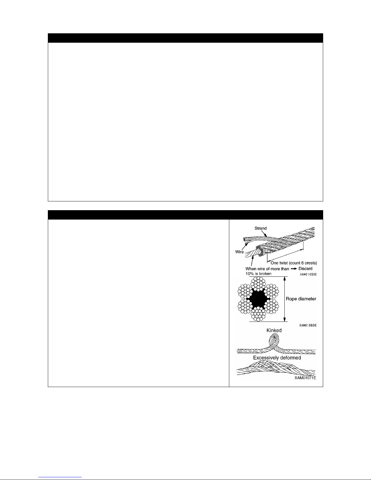
CAUTIONS WHEN HANDLING WIRE ROPE
• Wire ropes can wear out from constant use or old age, so be
sure to
inspect every time before work, and replace
immediately if at or beyond the replacement standard.
At the same time, inspect the sheave at the tip of the boom
and the sheave of the hook block. Damaged sheaves
accelerate the damage of the wire ropes.
• Use wire ropes specified by us.
• Otherwise, the operator may get wounded by snipped wires
that are sticking out.
Always wear leather gloves when handling the wire rope.
• Do not use a wire rope of which any of the following applies:
• 10 % or more of wires of 1 strand (except a filler wire) of a
wire rope are snipped.
• The wire rope diameter abrasion is beyond 7
% of the
nominal diameter.
• Kinked wire rope.
• Excessively deformed or corroded wire rope.
• Affected by heat or sparks.

33
CAUTIONS WHEN OPERATING CRANE
• Stability of a crane is decisively critical in the transverse direction of the carrier. In
the diagonal
direction, although stability is increased, exceeding the rated load may result in damage of the
boom or Machine body. Do
not turn the moment limiter (overload prevention device) off, even if
operating in the diagonal direction.
• Be sure to check that the override switch is at the "OFF" (auto) position before operating the crane.
Do not attempt to operate the crane when the override switch is at the "ON" (cancel) position.
The override switch is permitted to be at the "ON" (cancel) position o
nly during inspection or
maintenance works.
•
Perform work while paying attention to the display and warning of the monitor of moment limiter
(overload prevention device).
•
Attempt to work beyond the capacity of the Machine may cause serious accidents and failures
caused by for instance tripping or fluctuation. Observe the rated total load chart when operating the
crane.
• Perform the crane operation slowly.
Sudden use of lever or accelerator may cause risks such as shaking, dropping of the load or
collision with the surroundings. Be especially careful to be slow during the slewing operations.
• When operating the crane, appoint a work supervisor and perform the work under the supervisor's
instructions.
Follow the supervisor's instructions on the method and procedure for the work. Determine the
method for details of mutual signs and follow the signs.
• Hoisting of lengthy load causes the load to lose balance and is dangerous. In the case of such load,
apply a rope to both ends of to stabilize the hoisted load.
• Do not allow unauthorized personnel to approach the working radius or under the load because of
risks of falling load and contact with load. This could cause a serious bodily accident. Also consider
that the working radius increases when the load is hoisted and the boom is deflected.
• Operations requiring more than the machine performance can cause accidents or failure. Crane
operations must always be carried out according to the rated total load chart.
• Be careful to prevent the wire rope and/or hoisted load from contacting an obstacle such as a tree or
steel when hoisting a load.
If caught by an obstacle, do not forcibly wind up the hoist load, but untangle the caught part before
winding up.
• Do not pull laterally, pull toward you or hoist diagonally. Such
attempt may cause the crane to
tumble or get damaged.
• It is dangerous to operate the crane under bad weather or at places where the view is not clear.
Work lamps or other lighting devices should be used in dark places.
When the view is bad because of bad weather (rain, fog, snow, etc.), stop the operation and wait
until the weather recovers.
• Do not use for purpose, for instance raising a person using a crane, other than the true purpose.
• If the alarm buzzer of the over-hoist detector sounds, immediately release your hand off the winch
lever. Winding-up of the hook block stops. Then
, operate the winch lever "downward" (push it
forward) to wind down the hook block. Also, a boom extending operation hoists the hook block. For
the distance from the boom and hook block, provide a sufficient allowance for operating the crane.
• When the boom is extended, the hook block is wound up. Operate the winch lever "downward" and
extend the boom while lowering the hook block.
• If an overload is caused during work, operate the winch lever "downward" and wind down the winch
to unload.
Do not violently raise or lower the boom. Such attempt may cause serious accidents by tumbling.
• The volume of the hydraulic oil in each of the cylinders changes depending on the temperature.
By leaving idle with a load being hoisted, as the time passes by the oil temperature drops and the
hydraulic oil volume decreases, and changes such as the boom derrick angle decrease and boom
length decrease may occur.
In that case, execute boom derricking operations and boom extension operations appropriately to correct.
• Do not leave the operator's seat when a load is hoisted. When leaving the operating position, first
unload and set the lock lever to "LOCK" position.
• When the hook block is not used, wind up the winch.
The hook block of an empty load may hit operators near the load.
• Operation while hoisting a vibro compactor or other vibration generating attachment is in principle
prohibited. The winch or other unit may be damaged by the vibration of the attachment.

34
CAUTIONS ABOUT HIGH TEMPERATURE OIL WHEN OPERATING CRANE
When hydraulic oil temperature exceeds 80°C, high pressure hoses and seals can be
damaged by heat, and it may cause burning to skin from oil spray.
If temperature of hydraulic oil exceeds 80°
C, stop the operation and wait until the oil cools
down.
Continuous crane operation for a high lifting height with the accelerator pedal depressed will
increase the hydraulic oil temperature. Take special care during this operation.
CAUTIONS WHEN OPERATING WINCH
• Select a suitable number of wire rope falls to the hook and
boom length to the mass of hoisted load.
Refer to "OPERATION 4. HANDLING OF WIRE ROPE"
for details.
•
Do not allow persons to enter the area below the hoisted
load.
•
When hoisting a load, always stop once at the "takeoff"
position where the hoisted load leaves the ground. Check
subjects such as load stability and load force, then hoist up
the load.
• Do not pull laterally, pull toward you or hoist diagonally.
Such atte
mpt may cause the crane to tumble or get
damaged.
• Overwinding of the hook block may result in collision with
the boom, snipping the wire ropes and causing the hook
block and load to fall and may lead to serious accidents.
Take care not to overwind the hook block.
• Be careful to prevent the wire rope and/or hoisted load from
contacting an obstacle such as a tree or steel when hoisting
a load.
If caught by an obstacle, do not forcibly wind up the hoist
load, but untangle the caught part before winding up.
• Do not use the winch drum wire that is wound up irregularly.
If wound up irregularly, not only the wire rope gets damaged
and the lifetime is shortened, but it may snip the wire rope
and causes serious accidents.
Observe the following precautions to avoid wire rope from
winding up irregularly.
• Do not let the hook block tumble on the ground.
•
When lowering the hook block for a long distance for
underground works, be sure to leave more than 3 turns of
the wire rope on the winch drum.
• When decelerating from a high-speed hoisting, slacken the
accelerator pedal to lower the engine revolution, and then
slowly return the right-hand side machine operation lever. A
sharp returning of the right machine operation lever while
leaving the revolution at a high leve
l causes the hook to
jump up due to the rapid deceleration shock, resulting in an
irregular winding.
•
Use the winding and unwinding operations in the
high-speed mode when winding or unwinding the hook only.
Winding and unwinding a hoisted load in the high-speed
mode may cause such a serious accident as damage of the
boom or frame, or tumbling of the Machine.
• If the wire rope is twisted and causes the hook block to turn,
fully eliminate the twist before work.
Refer to the description under "OPERATION 4.3
MEASURE WHEN WINCH WIRE ROPE IS TWISTED".

35
CAUTIONS WHEN OPERATING BOOM
• Perform boom operation lever operation as slowly as
possible.
Especially avoid sudden lever operations when the load is
hoisted, which may cause the load to waggle and give large
impact to the Machine, and thus may damage the crane or
trip the Machine.
•
When the boom is lowered, the working radius increases,
and the rated total load that can be hoisted decreases.
When working while raising/lowering the boom,
pay extra
attention so that the mass of the load at the time the boom
is most lowered does not cause overloading.
• Pulling
of the load laterally by raising/lowering, and/or
extracting/retracting the boom is prohibited. Do not attempt
to do the above under any circumstances.
• When telescoping the boom, be cautious while checking the
winding of the hook block.
• When the boom is extended, the working radius increases,
and the rated total load that can be hoisted decreases.
When
working while extending/retracting the boom, pay
extra attention so that the mass of the load at the time the
boom is most lowered does not cause overloading.
CAUTIONS DURING SLEWING OPERATION
• Check the safety in the vicinity and honk the horn before
slewing.
• Perform the slewing lever operation as slowly as possible.
Make
sure to start smoothly, slew at low speed, and stop
quietly.
Especially avoid sudden lever operations when the load is
hoisted, which may cause the load to waggle and cause the
Machine to lose balance, and thus may damage the crane
or trip the Machine.
• Attempts to pull the load towards the machine or let the load
stand up by slewing operation are strictly prohibited. Do not
attempt to do the above under any circumstances.
• Be careful to prevent the wire rope and/or hoisted load from
contacting an obstacle such as a tree or steel when hoisting
a load or slewing.
If caught by an obstacle, do not forcibly wind up the hoist
load, but untangle the caught part before winding up.
COOPERATION HOISTING IS PROHIBITED AS A GENERAL RULE
Cooperative hoisting, where two or more cranes are used to hoist a single load, is prohibited as
a general rule.
Cooperative hoisting is a highly dangerous operation that may invite tumbling of the Machine
due to deviated center of gravity, fall of hoisted load and damage of the boom.
If cooperation hoisting is required for unavoidable reasons, discuss and establish a work
scheme under the responsibility of the user, let the worker fully acknowledge the work method
and procedures, and only proceed under the direct leadership of the work supervisor.
Also, observe the following cautions:
• Use the cranes of same model.
• Choose the Machine model that can handle sufficiently larger load than the load to be
hoisted.
• Make sure only one person gives signals.
•
Limit the crane operations to single operations as a rule, and do not attempt any slewing
operation.
• Appoint one responsible sling operator who is most experienced.

36
CAUTIONS FOR WORK AT WORKPLACE WHERE LIFT BELOW GROUND LEVEL IS
PERFORMED
• When lowering a wire rope in work underground, leave at least three loops of wire rope on
the winch drum.
• Make sure to give signals.
• Perform crane operation with extra care.
CAUTIONS ON TAVELING WITH HOISTED LOAD
Hoisted load traveling operation is in principle forbidden, because it is extremely unstable and
dangerous.
When inevitably performing a traveling with a hoisted load, observe the following. Negligence
of the precautions may cause serious bodily accident.
• Strictly observe the precautions described in the instruction manual.
Refer to the descriptions under "OPERATION 3.24.1
PRECAUTIONS IN OPERATION
DURING TRAVELLING HOIST ".
• Carefully observe the precautions on the operation details for the working posture prescribed
in the instruction manual.
Refer to the descriptions under "OPERATION 3.24.2
OPERATION POSTURE DURING
TRAVELLING HOIST ".
• As to the hoisted load, limit its weight within an allowance and assure its clearance above
ground.
• For a traveling operation, appoint marshallers.
• Remove any obstacle on the operation path and allow no operator to trespass the path.
• Operating for a distance exceeding the specified boom length is prohibited.
• Since the rated total load refers to the maximum value, suppress the load to a safe level in
accordance with operating situation.
• To perform a traveling operation with a hoisted load, keep the engine revolution to an idling
low speed so that the load will not swing and set the traveling speed to the low mode (1st
speed) to run slowly. Refrain from suddenly starting or stopping, or shifting to a high-speed
mode (2nd speed).
• During traveling with a hoisted load, do not shift the vehicle running speed mode or perform
crane operation.

37
3. TRANSPORT PRECAUTIONS
CAUTIONS DURING TRANSPORT
When transporting the Machine, there is a risk of inviting a serious bodily accident incurred by
an accident during transportation.
Strictly observe the following when transporting the Machine.
• Depending on the type of crane installed, the mass, height and total length of the machine
are varied, and thus check these details.
•
When traveling on a bridge or passing over a structure, check in advance the bridge and
viaduct to ensure that they can withstand the mass of the trailer and the machine, and firm
up the transportation route.
• When traveling on a public road, notify the competent authority to receive permission for the
transportation.
• The Machine may require disassembled transportation in accordanc
e with related
regulations (such as the enforcement ordinance of the Road Traffic Act). Contact us or our
sales service agency when conducting the transportation.
CAUTIONS WHEN LOADING OR UNLOADING
Pay particular attention to the loading or unloading operation
of the Machine, which may invite such an accident as
tumbling or falling of it.
When conducting a loading or unloading of the Machine,
strictly observe the following precautions:
• Select an area with horizontal and solid ground for setting
the Machine. In
addition, keep enough distance from the
roadside.
• Use the ramps under 15° or smaller angle. In addition,
decide the clearance between ramps to meet the center of
the crawler.
•
Use the ramps that have fully strong width, length and
thickness, and that enable safe loading/unloading.
Reinforce with blocks or other substances if the ramps
deflect much.
• Remove the mud and other substances from the footing to
prevent the Machine from skidding over the ramps. Remove
the substances stuck on the ramps such as grease, oil or
ice, and keep clean.
Be especially careful on the rainy days when slips may
easily occur.
• Be sure to set the switch of automatic deceleration to OFF
(cancel).Turning the automatic deceleration switch ON
rapidly levy up the engine revolution, resulting in a sudden
start of acceleration, and thus it is very dangerous.
• When loading or unloading the Machine, be sure to set the
Machine to a traveling posture and fix the hook block to the
Machine body by using wire ropes.
Refer to the descriptions under "OPERATION 3.7
MACHINE TRAVELLING POSTURE ".
• When loading or unloading, set the engine rotation to low
idling (low speed rotation) and operate slowly by low speed
travels.
• Always move backward when loading the Machine. Moving
forward may cause the machine to fall.
•
Do not operate any other lever than traveling levers
(forward/reverse traveling) on the ramp boards.
• Never change direction on the ramp. Temporarily leave the
ramp before correcting the direction.

38
CAUTIONS WHEN LOADING OR UNLOADING (CONTINUED)
• Across the border of ramp and loading deck, the center of
gravity of the Machine rapidly moves and thus the Machine
becomes unstable. Accordingly, pass the border
particularly slowly.
• When unloading the Machine and placing the load onto an
earth fill or platform, secure sufficient width, strength and
inclination of the ground or the platform.
•
Set the Machine to a traveling posture and be slow when
operating to change the direction on the trailer platform
where the footing is unstable.
• After loading the Machine, be sure to lock the cabin door.
Otherwise, the door may flung open during transportation.
•
After loading the Machine, apply the wood blocks so that
the Machine does not move, and securely fix with wire
ropes or other means.
Refer to the descriptions under "OPERATION 5.1
LOADING/UNLOADING".
Refer to the descriptions under "OPERATION 5.3
CAUTIONS DURING TRANSPORTATION."

39
4. MAINTENANCE PRECAUTIONS
4.1 PRECAUTIONS BEFORE MAINTENANCE
PUT UP A WARING SIGNBOARD DURING INSPECTION/MAINTENANCE
• When warning sign "DANGER. DO NOT OPERATE!" is put
up, the Machine is being inspected and under
maintenance. Do not start the engine and refrain from
touching operating levers. Disregarding the warning sign to
operate the Machine may give rise to the danger of
involving the preparing personnel into the rotating parts or
movable parts of the Machine, resulting in serious injury.
•
Put up additional warning signs around the Machine as
required.
Part number of warning signboard: 585-4738300
When this warning signboard is not used, store it in a tool
box. If no tool box is available, keep it in a holder for the
instruction manual.
TIDY UP WORKPLACE
• Always tidy away tools, hammers and
other things that obstruct the working area; grease
and oil should be wiped off immediately after use to assure safe operations.
An untidy workplace may cause safety hazards and result in injuries to personnel.
SELECTING A WORKPLACE
• For inspection and maintenance, select an area with flat and solid ground.
• Select such a place where no risk of landslide, rock fall or flooding is feared.
KEEP AWAY UNAUTHORIZED PERSONNEL
During maintenance servicing of the Machine, never allow any personnel except the required
persons.
Appoint monitoring personnel as required.
FOLLOW SUPERVISOR'S INSTRUCTION DURING TEAMWORK
Appoint a person who supervises the work and follow his/her instructions in case of Machine
repair or installing/uninstalling a work device.
Unexpected accidents due to misunderstood communication between workers may occur
during teamwork.

40
KEEP ENGINE STANDING STILL DURING INSPECTION AND MAINTENANCE
•
Before starting inspection and maintenance servicing, be
sure to retract the crane and stop the engine.
• Turn the starter switch to ON position and move each of the
left and right operating levers back and forth to the full
stroke for 2 to 3 times so that the residual pressure in the
hydraulic circuit is relieved. Set the lock lever (1) to LOCK
position (L) to turn the starter switch OFF.
• Check to ensure that the battery relay is turned OFF and
main power current is not turned ON.
After turning the starter switch OFF, wait for
approximately 1 minute and push the horn switch. If the
horn is not honked, no current is ON.
• Turn the disconnect switch in the battery box OFF to shut
off the power supply circuit in order to prevent the system
from unexpectedly activated during inspection and
maintenance servicing.
• Apply pawls to prevent crawler from moving.
WORK BY AT LEAST TWO PERSONS DURING MAINTENANCE WITH ENGINE
RUNNING
To prevent accidents, do not attempt maintenance when the
engine is running.
Always observe the following in case of maintaining with the
engine running for unavoidable reason.
• One person should occupy the operating seat to be ready
for stopping at any time, and keep communications each
other.
•
When working near such rotating parts as fan, belt, and
winch drum, keep the operator's body and any object that
can be readily caught away from these parts.
•
Never allow any object or tool to fall on or insert into the
rotating parts of fan, belt and winch drum. Such an object
may hit the rotating part or spring back from it, and thus it is
dangerous.
• Do not touch operation levers. If it is unavoidable to use the
operation levers, always give a sign to the other person and
let him/her evacuate to a safe place.
• Set the lock lever (1) to the "LOCK" (L) position.
Refer to the descriptions under "MAINTE
NANCE 12.
RELIEVING INTERNAL PRESSURE OF HYDRAULIC
CIRCUIT."
• Do not touch operation levers and pedals. If
it is
unavoidable to use the operation levers and pedals, always
give a sign to the other person and let him/her evacuate to
a safe place.
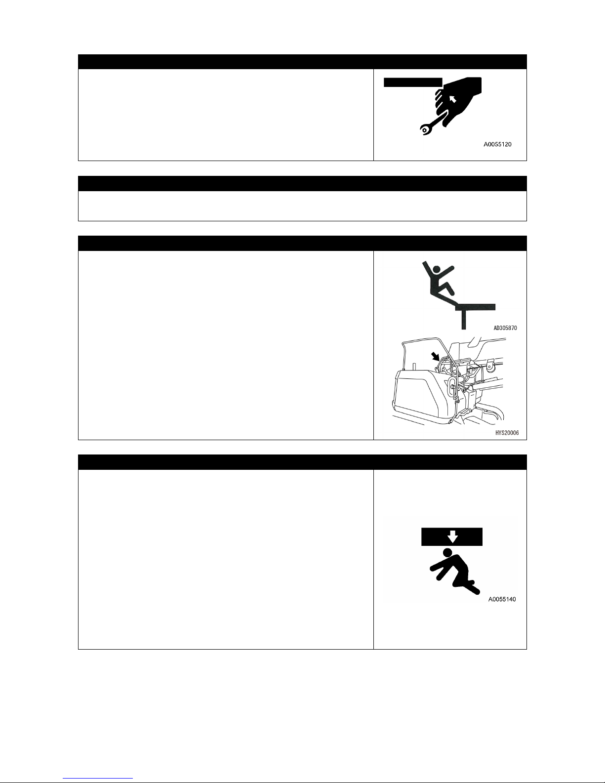
41
USE APPROPRIATE TOOLS
Use proper tools and handle them in correct manners. Using
a damaged or deformed tool and using it for any purpose
other than its intended application may giving rise to a serious
bodily accident.
PRECAUTIONS FOR WORKING AT HIGH ELEVATION
Secure scaffolding by using a workbench with the stairs when working at high elevation.
CAUTIONS WHEN WORKING ON MACHINE
•
Tidy the footing to avoid falling and always observe the
following precautions during maintenance on the Machine.
• Do not spill oil or grease.
• Always tidy away tools.
• Beware of the footing when walking.
• Remove dirt, oil and grease from the sole of shoes.
• Never jump off. Use
a platform and handrail, and secure
your body in three locations (both feet and one hand, or
both hands and one foot) when climbing up or down the
Machine.
• To prevent oneself from the risk of bodily accidents caused
by falling or stumbling due to slipping, never step on a hood
or cover.
• When working on the engine hood, use a safety belt.
CAUTIONS WHEN WORKING UNDER THE MACHINE AND CRANE
• For lifting up the Machine, use a hoist or hydraulic jack in
good condition and having enough strength to withstand
the weight of components. Note
that the hydraulic jack
should not be used for lifting any part that is damaged, bent
or twisted. Further
, the wire rope to be used for hoisting
shall not include broken wires, be reduced in diameter or
kinked. Do not use a hook that is bent or damaged.
•
When unavoidably going under the lifted Machine to
perform inspection and maintenance servicing, securely
support the Machine by using blocks and stays that are
sturdy enough to withstand the Machine weight. Failure to
support the Machine securely may cau
se falling of the
Machine, resulting in a serious bodily accident.
• Do not use concrete blocks for supporting the Machine. A
concrete block may readily be broken even under a light
load.
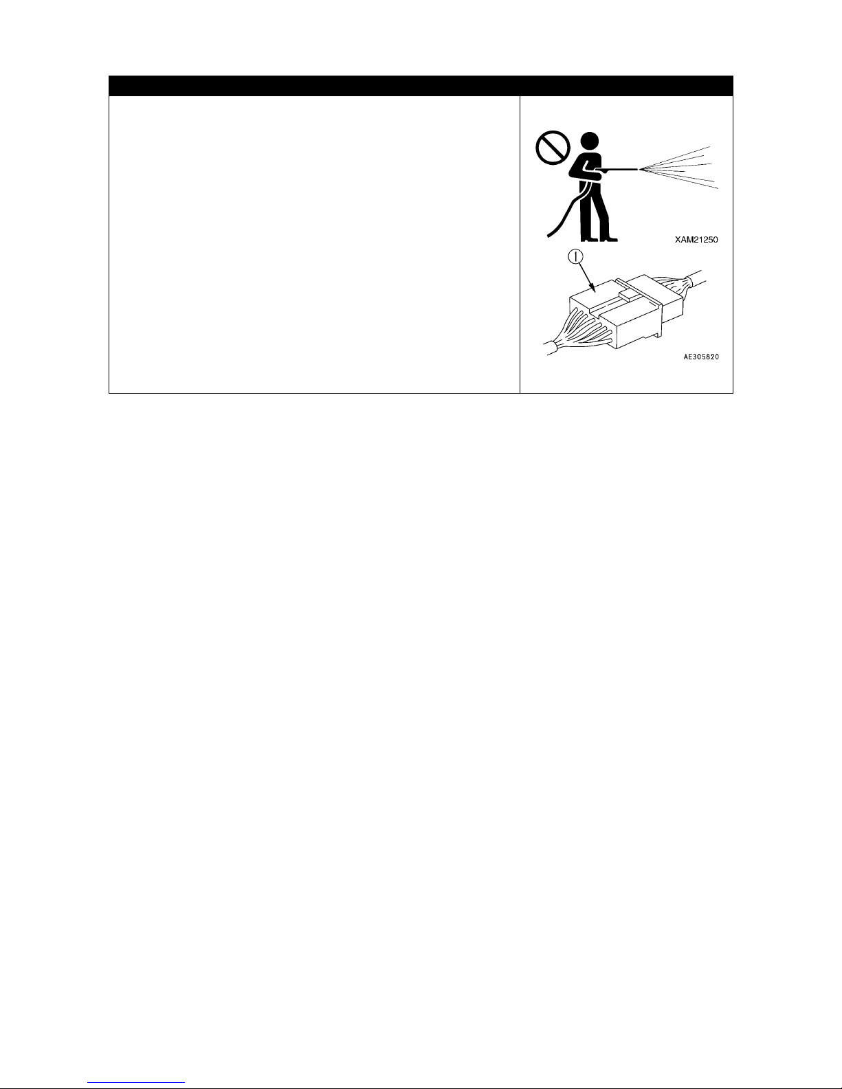
42
CLEAN BEFORE INSPECTION OR MAINTENANCE
• Before starting an inspection or maintenance, clean the
Machine and prevent rubbish from entering the Machine
and make sure the safety will be ensured during
maintenance.
•
Attempt to inspect or maintain the Machine still dirty not
only lessens chance of locating faulty part, but may cause
rubbish or mud entering your eye, or slipping and tripping
that result in injury.
• Always observe the following when washing the vehicle.
• Use antis lip shoes to prevent slips and trips caused by
wet foothold.
• Put on protective equipment when using a high pressure
steam car washer. Avoid an accident from high pressure
water which causes skin laceration or mud or other
substance to fly to eyes.
•
Do not directly spray water onto the electrical system
(sensors and connectors (1)). Water
entering the
electrical system is dangerous and will cause faulty or
improper operations.
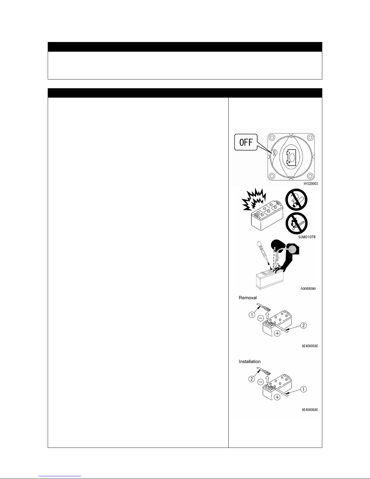
43
4.2 PRECAUTIONS DURING MAINTENANCE
CAUTIONS DURING WELDING REPAIR
Conduct welding operation in a location with good facility, and, only authorized personnel are
permitted to be engaged in the welding work.
Unauthorized personnel are strictly prohibited since risks such as gas generation, fire and
electrical shock are present when welding.
CAUTIONS WHEN HANDLING BATTERY
Before starting inspection of the battery and handling, set the
starter switch to OFF position and the disconnecting switch
inside the battery box to OFF position to shut off the power
supply circuit in order to prevent the system from
unexpectedly activat
ed during inspection and maintenance
servicing.
Because the battery produces hydrogen gas, sparks around
the battery can cause an explosion.
Moreover, the battery solution contains diluted sulfuric acid.
Wrong handling of it may cause a bodily accident, explosion
and fire, and therefore always observe the following
precautions:
• AVOIDING THE RISK OF BATTERY EXPLOSION
• If the battery fluid level decreases to the LOWER LEVEL
or further below, do not use the bat
tery or recharge it.
Otherwise, an explosion may occur.
Never fail to conduct the regular inspection of battery
fluid level and refill purified water (such as battery
replenisher available on the market) to the UPPER
LEVEL.
• Do not smoke or use fire near the battery.
• During recharging the battery, it generates hydrogen gas
that is flammable.
Before recharging it, dismount if from the Machine and
conduct the recharging in a well ventilated place. During
the recharging process, remove the battery cap.
• Securely tighten the battery cap afterwards.
• AVOIDING THE RISK OF DILUTED SULFURIC ACID
• Always wear protective glasses and rubber gloves before
handling the battery.
• I
f the battery fluid enters your eyes, wash immediately
with water and see a doctor as soon as possible.
• If the battery fluid contacted clothing or skin, immediately
wash away by huge quantity of water.
• DISCONNECT BATTERY TERMINAL
Before starting the repair work of electric system and
performing a welding operation, first turn the starter switch
OFF, wait for about one minute, and then disconnect the
battery terminals to interrupt the flow of electric current.
• DANGER OF SPARKING
To prevent sparking, strictly observe the following
precautions:
• Never allow such a metallic object as a tool to come in
contact with battery terminals. Do not leave tools or other
object around the battery.
• When removing the battery, be sure to discon
nect the
grounding (-) end terminal first. Conversely for mounting
it again, first connect the positive (+) end terminal and fix
the grounding end (-) terminal finally.
• Fix the battery terminal securely.
• Fix the battery body to the specified position securely.
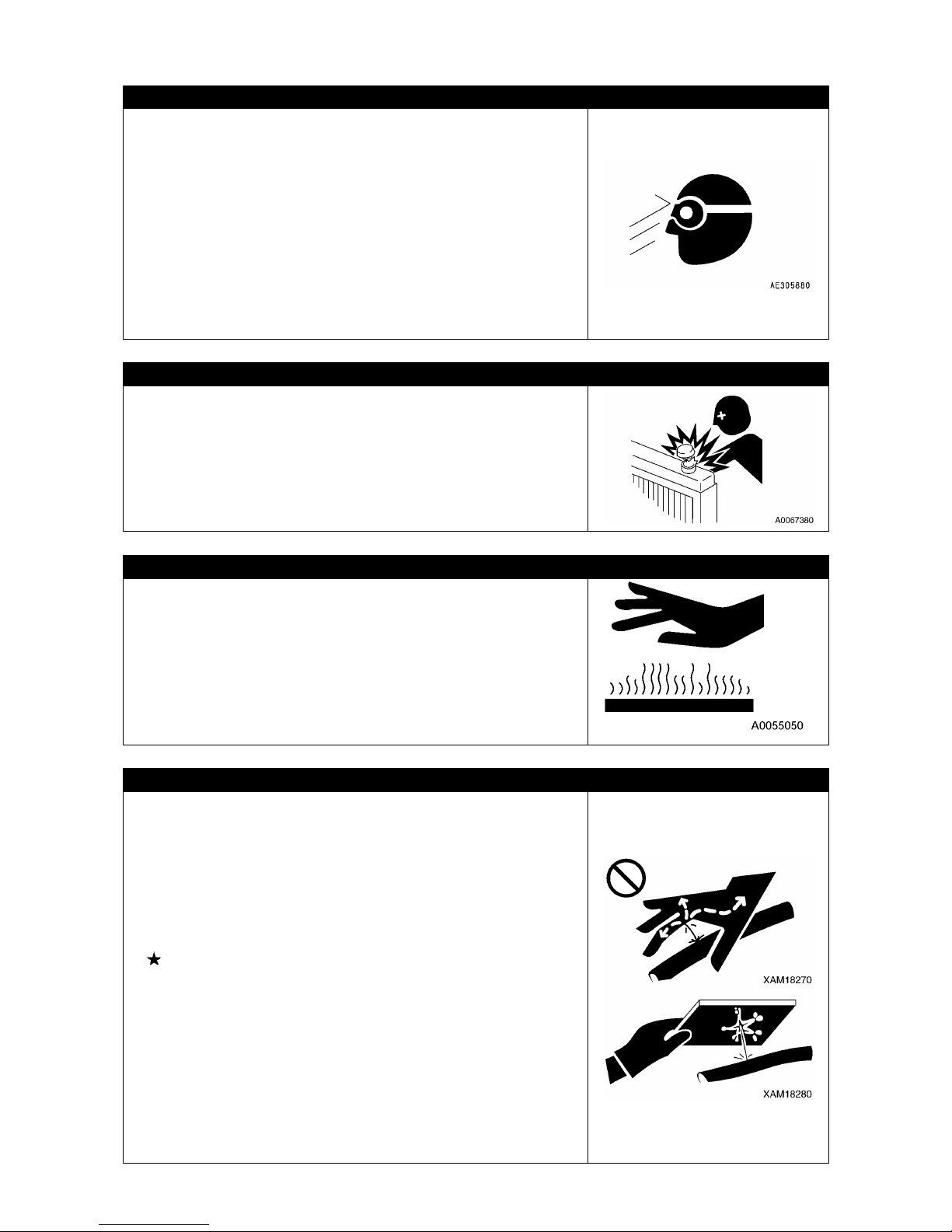
44
BEWARE OF CHIPS WHEN WORKING WITH HAMMER
Working with a hammer may cause a serious bodily accident
because of springing off of a pin or littering of metallic chips.
Strictly observe the following.
• Hitting a pin or the like may give rise to shattering of broken
chips to hurt people nearby. Before
starting such a work,
make it sure that no one is staying around you.
•
Knocking a pin off with a strong force may cause the pin
flying out to hurt a person nearby. Do not allow anyone to
stay around.
• When knocking such a hard metallic part as pin or bearing,
there is a risk of causing a serious bodily accident by
flaying objects. Be sure to wear protective equipment such
as goggles, gloves and helmet.
BE CAUTIOUS OF HEATED COOLANT
When checking or discharging the coolant, ensure that the
radiator cap has been cooled down so that it can be touched
by bare hand in order to prevent a burn injury because of the
spewing hot water or steam.
When removing the
cap, first loosen it slowly to relieve
radiator internal pressure, and then take it off.
BEWARE OF OIL AT ELEVATED TEMPERATURES
When checking or discharging oil, ensure that the radiator
cap and plug have been cooled down so that they can be
touched
by bare hand in order to prevent a burn injury
because of the spewing hot oil or coming in contact with parts
heated at high temperatures.
When removing cap and plug, first loosen it slowly to relieve
radiator internal pressure, and then take it off.
BEWARE OF OIL UNDER HIGH INTERNAL PRESSURE
The hydraulic system is constantly subjected to an internal
pressure. Thus
, when checking or replacing the piping and
hoses, failure to ensuring that the internal pressure of the
circuit has been relieved gives
rise to a serious bodily
accident.
Strictly observe the following.
• Never replace piping or hoses while the hydraulic circuit is
subjected to an internal pressure. Be
sure to relieve the
pressure of the hydraulic circuit.
Refer to the descriptions under
"MAINTENANCE 12.
RELIEVING INTERNAL PRESSURE OF HYDRAULIC
CIRCUIT."
• If an oil leakage is taking place, the piping, hoses and their
periphery are wet. Check to ensure that the piping is free
from fissures and the hoses have no cracking or swelling.
Be sure to wear protective equipment such as goggles and
gloves during the inspection work.
•
High pressure oil leaking through a small hole may
puncture the skin or destroy eyesight upon direct contact. If
this happens, wash away with flowing clean water and see
the doctor as soon as possible.

45
BEWARE OF FUEL UNDER HIGH INTERNAL PRESSURE
In the engine fuel piping, an internal pressure is generated during engine operation. Before
starting the inspection and maintenance servicing of fuel piping, wait until its internal pressure
is relieved. After stopping the engine, wait for 30 seconds or more before starting the work.
HANDLING HIGH PRESSURE HOSE AND PIPING
If fuel leaks from a hose or piping, there occurs a risk of fire
and malfunction leading to a serious bodily accident.
When leakage of oil or fuel is detected at a loosened joint or
mounted spot of hoses or piping, immediately stop the work
and re-tighten them with a specified tightening torque.
Also, when recognizing a damage or deformation of hoses
and piping, consult with us or our sales service agency.
If any of the following conditions is found, replace the faulty
parts:
• Damage of a hose or deformation of sleeve
• Scratch or truncation of the covering layer, or exposure of
wire reinforcement layer
• Covering layer is partially swollen
• Indication of twist or collapse on a movable part of hose
• Foreign object buried in coating
BEWARE OF HIGH VOLTAGE
During or at immediately after stopping an engine operation,
the inside of engine controller and around the engine fuel
injector are under a high voltage, and thus an electric shock
may occur.
Never touch the inside of engine controller and engine fuel
injectors. If there is a need for touching these parts, consult
with us or our sales service agency.
BEWARE OF NOISE
Use ear protection or ear plugs during long-term noise exposure, such as engine maintenance
servicing. Large noise in the surroundings may cause hearing difficulty or deafness.
WHEN ADJUSTING CRAWLER TENSION, BEWARE OF HIGH PRESSURE GREASE
• The grease inside the crawler adjusting unit is under high
pressure.
Conducting the adjustment in an unauthorized procedure
may cause the grease discharging plug (1) to jump out,
resulting in a serious bodily accident.
• When loosening the grease discharging plug (1) to loosen
the tension of crawler, do not rotate it more
than 1 turn.
Also, loosen the grease discharging plug (1) slowly.
• Do not allow your face, limbs and body to come closer to
the grease discharging plug (1).
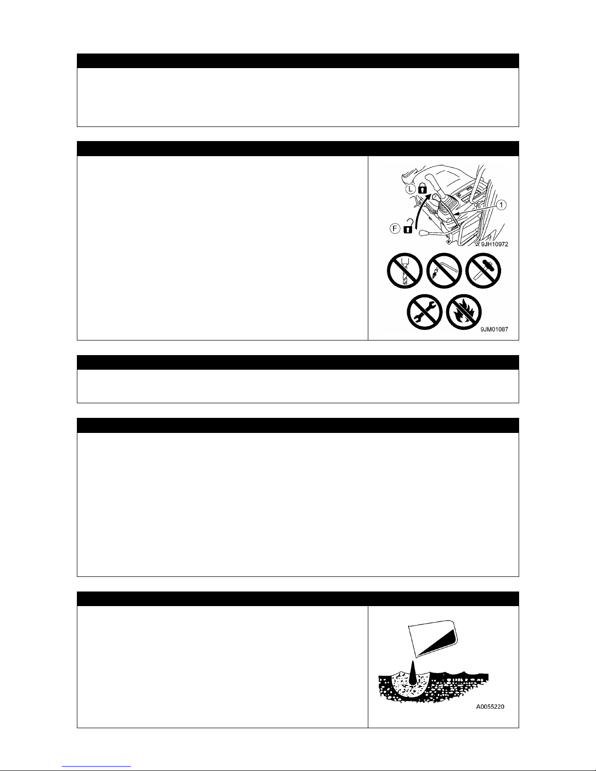
46
NEVER DISASSEMBLE THE RECOIL SPRING
Under no circumstances, refrain from disassembling the recoil spring assembly.
In the recoil spring assembly that is intended for buffering the idler, a strong spring is installed.
An inadvertent disassembling it causes the spring to jump out, inviting a serious bodily
accident. Contact us or our sales service agency if its disassembling is required.
CAUTIONS WHEN HANDLING ACCUMULATOR / GAS SPRING
• This machine is equipped with an accumulator. After
stopping the engine, be sure to set the lock lever to LOCK
position (L).
• Since the accumulator and gas spring is encapsulated with
high pressure nitrogen gas, an erroneous handling of them
may cause an
explosion and subsequent serious bodily
accident. Strictly observe the following.
• Never disassemble them.
• Do not allow fire
to come closer to them or throw them
into fire.
• Do not attempt boring, boring or gas cutting.
• Do not knock them, tumbling them or give impact to them.
• When disposing of them, removal of filled gas is required.
Contact us or our sales service agent.
BE CAUTIOUS OF COMPRESSED AIR
When using the compressed air for cleaning, there is a risk of serious bodily accident because
of scattering waste objects.
Be sure to wear goggles, dust mask and gloves.
MAINTENANCE AND INSPECTION OF AIR-CONDITIONER
• If the refrigerant of air-conditioner get into the eyes, loss of sight may occur and if it comes
into contact with skin, it gives rise to a frostbite. Never loosen parts of the cooling circuit.
• When conducting the maintenance servicing of the air-conditioner, follow the Fluorocarbon
Refrigerants Emission Regulating Act.
•
Users (possessors) of the Machine are obligated to conduct periodic inspections as
stipulated by the Fluorocarbon Refrigerants Emission Regulating Act. Inspect once in three
months. Even when the air-
conditioner is not used during off season, the inspection is
required.
Check item
• Abnormal vibration and abnormal operation noise of the compressor
• Oil oozing out on and around the compressor
• Scratches, corrosion, rust and other blemishes on the compressor
• Frosting of air-conditioner heat-exchanger in the cabin.
CAUTIONS WHEN TREATING WASTE
In respect of the environment protection, pay sufficient attention to
the treatment of waste matters.
• Be sure to use drums and tanks to hold the discharged waste
liquid. Never allow waste liquid to flow on the ground, into river,
drainage, sea or lake.
•
Observe the applicable legal regulations and rules when
disposing of this Machine as well as harmful substances such as
oil, fuel, solvent, filter or battery.
• When disposing of an air-conditioner, the recovering work must
be consigned to a Class 1 fluorocarbon refrigerants filling and
recovering contractor registered by the competent authorities.

47
SELECTING WINDOW WASHER SOLUTIONS
Use the window washer based on ethyl alcohol.
Do not use a washer solution based on methyl alcohol because it may hurt the eyes.
PERIODIC REPLACEMENT OF CRITICAL PARTS
• To assure the prolonged and safe use of the Machine, be sure to conduct the periodic
replacement of parts that are particularly related to safety such parts as hoses and seat
belts. Materials of these parts tend to change their properties with elapse of service time and
will degrade, abrade and show fatigue with repeated services, and thus may cause a serious
bodily accident. Also
, it should be noted that their service life can hardly determined by
inspecting their appearance.
Refer to the descriptions under "MAINTENANCE 4.
PERIODIC REPLACEMENT OF
CRITICAL PARTS ".
• If any abnormality is observed in a critical part by appearance, replace it even if it has not
reached the time for regular replacement.
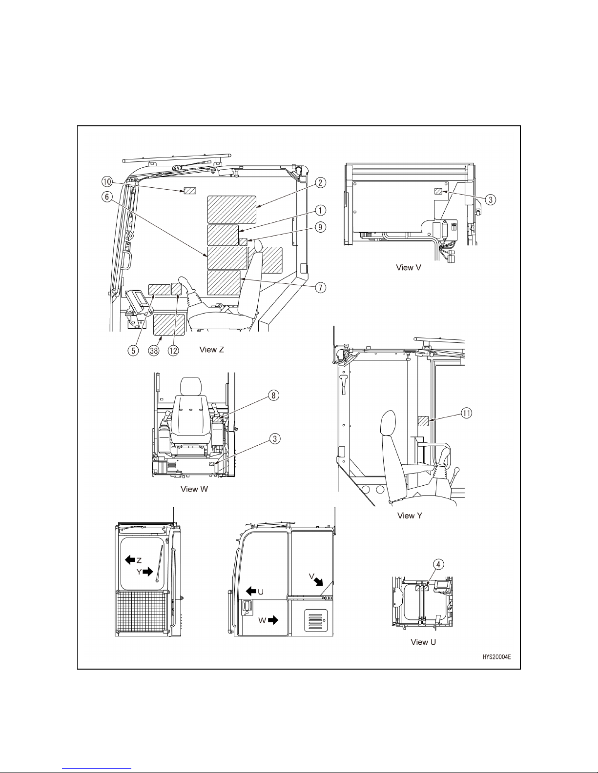
48
5. SAFETY LABEL LOCATIONS
Keep safety labels clean and visible at all times.
If lost, replace immediately or apply for a new one.
There are other labels than safety labels shown below and treat them in the same manner.
[SAFETY LABEL LOCATIONS IN THE CABIN]

49
[SAFETY LABEL LOCATIONS OUTSIDE OF THE CABIN]

50
[SAFETY LABEL LOCATIONS IN THE ENGINE ROOM]
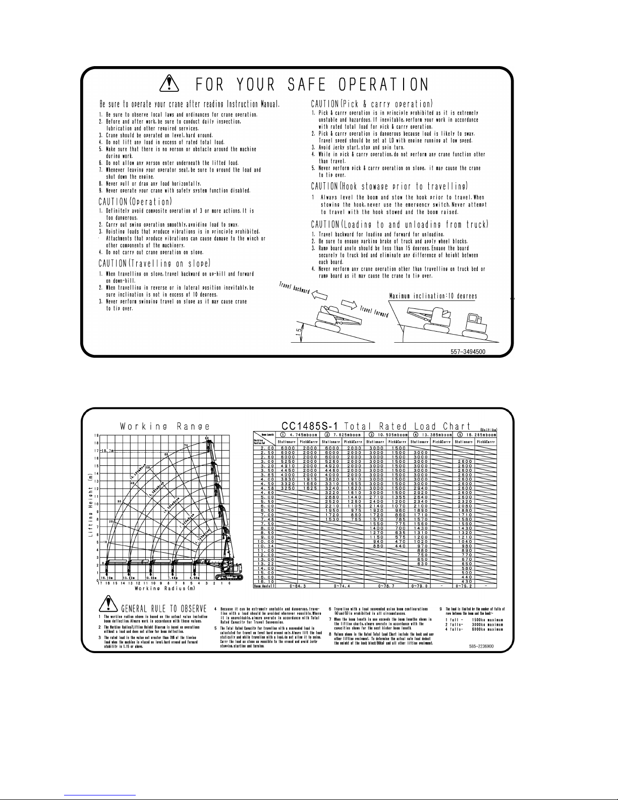
51
(1) Safe operation (557-3494500)
(2) Working range diagram (585-2236900)

52
(3) Washing caution (300-4213900)
(4) Lever operating patterns (585-3555400)
(5) Warning on switching numbers of falls (585-3555500)

53
(6) Operating the moment limiter (585-2237000)
(7) Warnings on operation, inspection and maintenance (584-3469700)
(9) Cautions in repairing window
breakage (585-4739300)
(8) Operation prohibiting tag (585-4738300)

54
(13) Cautions for high temperatures of muffler (349-4427800)
(11)
Cautions in opening/closing
the front window (585-4738400)
(10) Cautions in retracting the front
window glass (CL000160010)
(12) Cautions in slewing
(584-4588100)
(15) Diesel fuel (585-4738600)

55
(22) Warning on body hoisting positions (584-3437800) (2 spots)
(16) Cautions against the risk of burns
(CL000170000) (2 spots)
(18) Caution against rotating parts in
the engine room (CL000080000)
(17)
No entry within the slewing area
(CL000180013)
(19)
Cautions for plug popping out
(CL000190010)
(
20) Caution against suffering from electric
shock by battery cable (CL000200000)
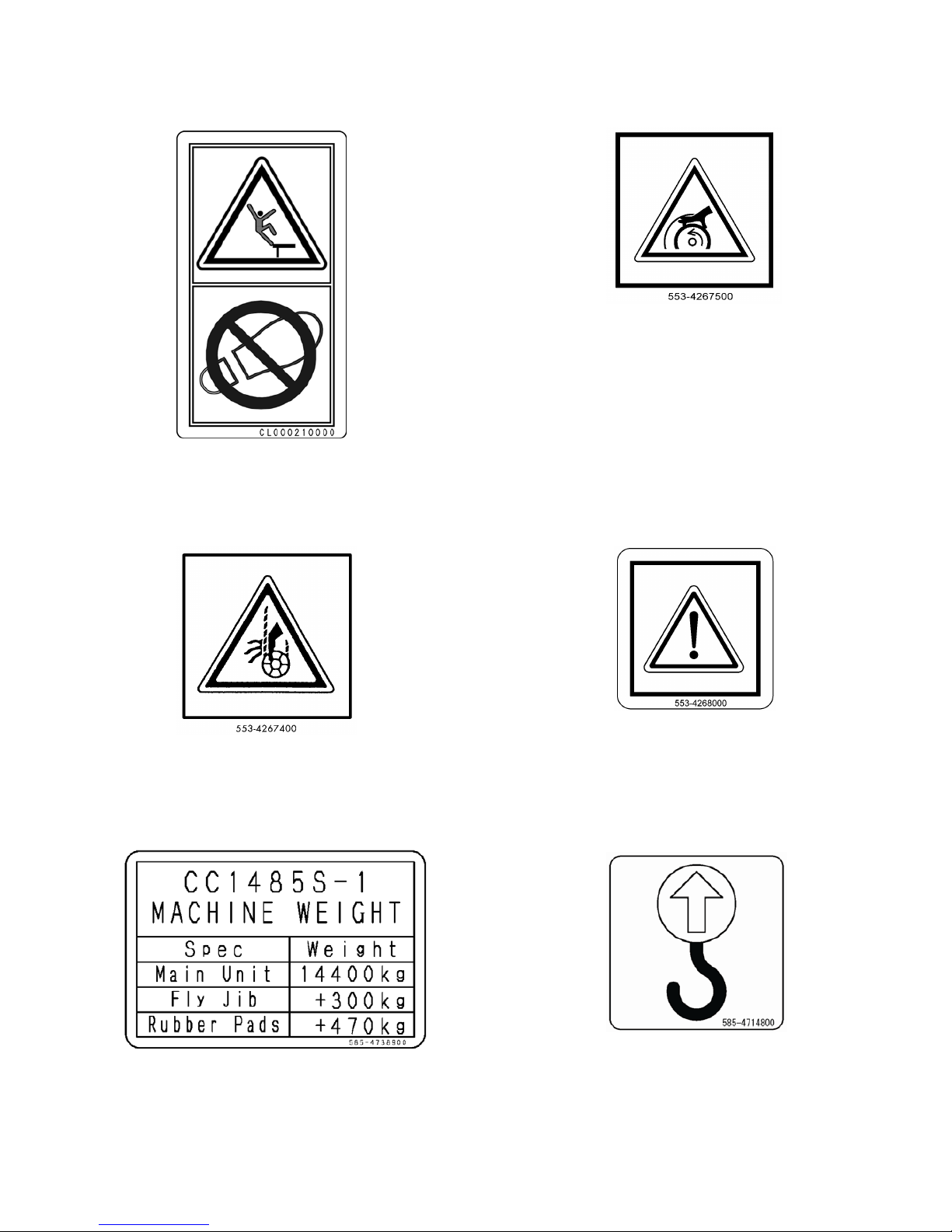
56
(23) Cautions on the fenders
(CL000210000)
(24) Warning for winch (553-4267500)
(25) Caution against being entangled
by the hook block (553-4267400)
(2
6) Warning (55 3-4268000)
(2
7) Body mass indication
(585-4738900)
(2
8) Hoisting position
(585-4714800) (2 spots)

57
(2
9) Tethering position indication
(585-4714200) (4 spots)
(
30) Warnings for the accumulator
(CL000220030)
(34) Warning on boom hoisting
Accessories (103-4576900)
(
31) Caution against rotation
(557-4632500)
(3
2) Do not step on
(584-4581700) (2 spots)
(36) Cautions on override switch
(585-4739200)
(37) Cautions against the risk of burns
in the engine room (585-4727600)
(33) Cautions on disconnect switch
(585-4714100)
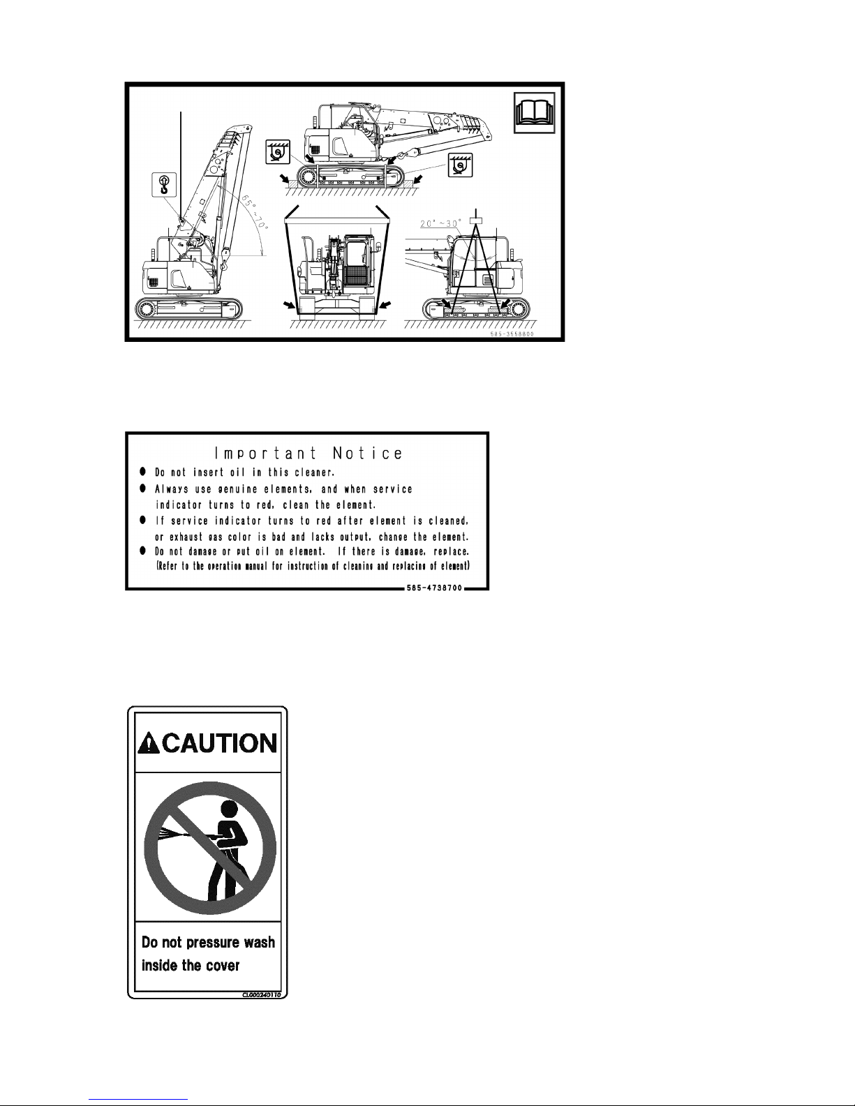
58
(3
8) Hoisting machine / Fixing machine (585-3558800)
(3
9) Caution air cleaner (585-4738700)
(
40) Caution pressure wash
(CL000240110) (2 spots)

59
OPERATION
1. NAME OF EACH SECTION 60
2. EXPLANATION OF ALL EQUIPMENT
63
3. OPERATION
130
4. HANDLING OF WIRE ROPE 192
5. TRANSPORTATION 197
6. HANDLING WHEN COLD 206
7. LONG-TERM STORAGE 208
8. TROUBLESHOOTING 210
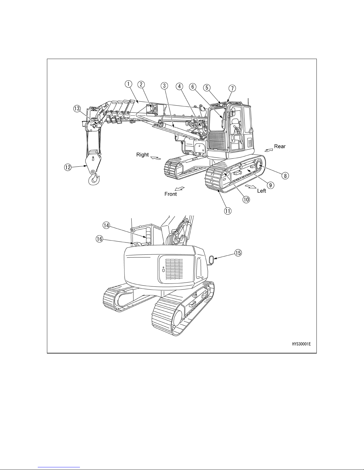
60
1. NAME OF EACH SECTION
1.1 MACHINE UNITS
(1) Boom
(2) Working lamp
(3) Boom Derrick Cylinder
(4) Winch
(5) Head lamp
(6) Wiper (Front window)
(7) Wiper (Roof Window)
(8) Sprocket, travel motor
(9) Track Frame
(10) Idler
(11) Crawler
(12) Hook block
(13) Overwinding detector
(14) Rotating warning lamp
(15) Rear view mirror
(16) Rear view camera
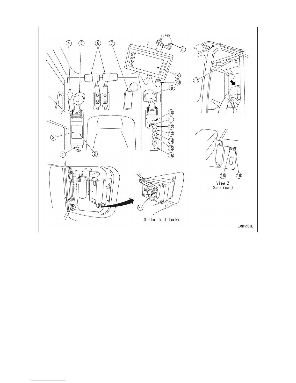
61
1.2 CRANE OPERATION UNITS
(1) Maintenance switch
(2) Air conditioner operation unit
(3) Car radio
(4) Lock lever
(5) Left work operation lever (Winch 2-speed
selector switch on knob part)
(6) Travel lever
(7) Accelerator pedal
(8) Machine monitor
(9) Right work operation lever (Horn switch
on knob part)
(10) Starter switch
(11) Fuel adjustment dial
(12) Lamp switch
(13) Front window wiper switch
(14) Roof window wiper switch
(15) Buzzer canceling switch
(16) Accessory power supply
(17) Room lamp switch
(18) Emergency accelerator driving switch
(With guard)
(19) Slewing parking brake emergency
canceling switch (With guard)
(20) Emergency stop switch
(21) Levelling instrument
(22) Override switch
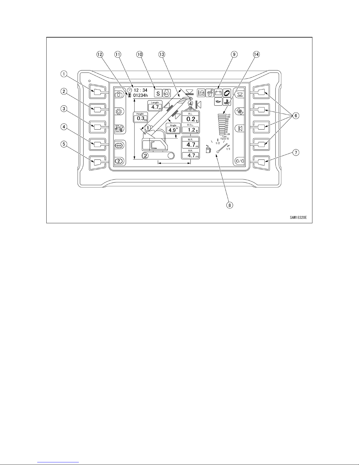
62
1.2.1 MACHINE MONITOR COMPONENTS
(1) Rear view camera selector switch
(2) User mode switch
(3) Hook storage switch
(4) Travel mode selector switch
(5) Travel 1st speed/2nd speed selector
switch
(6) Working range regulation setting and
canceling switch
(7) Working range regulation setting
check/all canceling switch
(8) Fuel gauge
(9) Warning display
(10) Working mode display
(11) Clock display
(12) Hour meter display
(13) Moment limiter status display
(14) Moment limiter load factor display
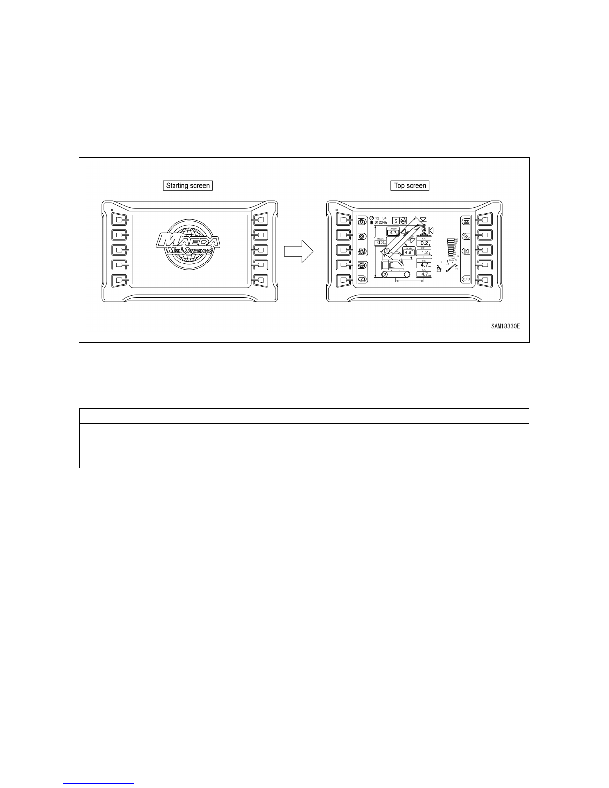
63
2. EXPLANATION OF ALL EQUIPMENT
The following is an explanation of equipment necessary for machine operation and work operation.
It is most important that you to correctly understand the operation method of this equipment and the
display content in order to perform correct, safe and comfortable work.
2. 1 MACHINE MONITOR
[1] STARTING SCREEN
•
When the starter switch is turned "ON", the starting screen is displayed.
• After the starting screen is displayed, the standby gauge is displayed and the screen is switched
to the top screen.
NOTES
When the engine is started, the battery
voltage can suddenly decrease depending on the
temperature and battery condition.
In such a case, the machine monitor display can temporarily disappear, but this is normal.
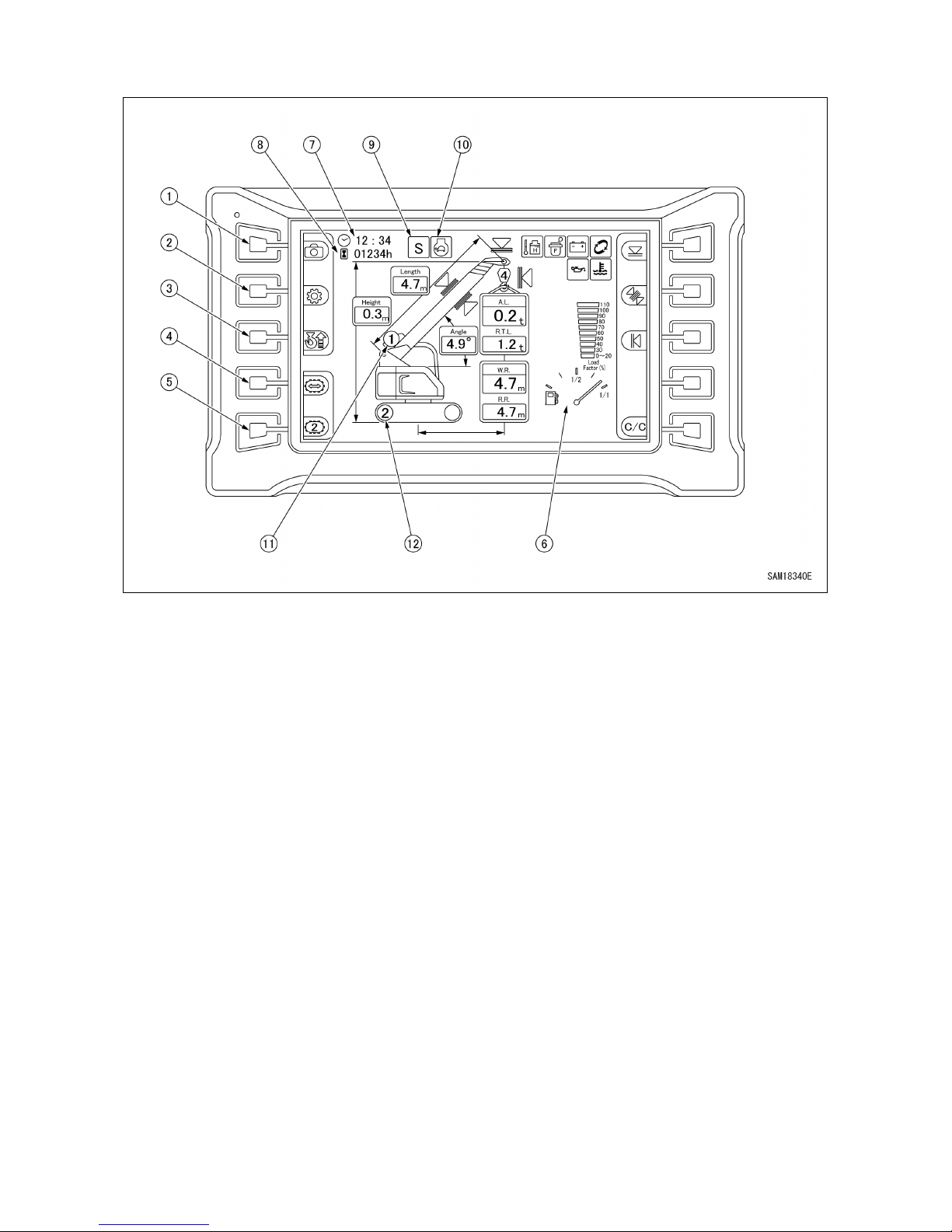
64
[2] TOP SCREEN
(1) Rear view camera selector switch
(2) User mode switch
(3) Hook storage switch
(4) Travel mode selector switch
(5) Travel 1st speed/2nd speed selector
switch
(6) Fuel gauge
(7) Clock display
(8) Hour meter display
(9) Working mode display
(10) Auto deceleration display
(11) Winch 1st speed/2nd speed display
(12) Travel 1st speed/2nd speed display
See "OPERATION 2.4.4 MOMENT LIMITER FUNCTIONS" for the name of the moment limiter parts.

65
2.1.1 MONITOR BASIC ACTION AND DISPLAY
[1] REAR VIEW CAMERA SELECTOR SWITCH
When the rear view camera selector switch (1) is pressed
on the top screen, the camera image is displayed on the
monitor.
When the home switch (HO) is pressed, the screen returns to
the top screen.
NOTES
If it is difficult to see the camera image, adjust the camera
angle.
[2] USER MODE SWITCH
When the user mode switch (2) is pressed on the top screen, the user mode is displayed.
(2-1) Auto deceleration ON/OFF change
(2-2) Working mode change
(2-3) Hook fall number change
(2-4) Rear-view camera auto ON/OFF
selector switch
(2-5) Monitor brightness adjustment
(2-6) Time setting screen
(2-7) Language setting
(2-8) Error history display
(2-9) Consumables display
(2-10) Switch operation sound ON/OFF change
(2-11) Home switch
(2-12) Display page change
(2-13) Software version check

66
[2-1] AUTO DECELERATION ON/OFF CHANGE
When the switch (2-1) is pressed, auto deceleration
ON/OFF can be changed.
• OFF: Maintains constant engine speed even if you do not
operate the controls for the preset duration.
• ON: Reduces engine speed if you do not operate the
controls for the preset duration.
When ON is selected, the auto deceleration display (10)
icon is displayed on the top screen.
[2-2] WORKING MODE CHANGE
When the switch (2-2) is pressed, the working mode can
be changed.
• S: Standard mode
• E1: Eco mode 1 (fuel economy-focused mode)
• E2: Eco mode 2 (low revolution mode)
When the working mode is changed, the working mode
display (9) on the top screen is changed.
[2-3] HOOK FALL NUMBER CHANGE
When the switch (2-3) is pressed and held, the hook fall
number can be changed.
• Four falls
• Two falls
• One fall
When the fall number is changed, the number on the hook
part of the moment limiter part changes and rated total load
changes.
Be sure to match the displayed number with the actual
hook fall number.
[2-4] REAR VIEW CAMERA AUTO ON/OFF
SELECTOR SWITCH
When the switch (2-4) is pressed, the rear view camera
display mode can be switched between manual and
automatic.
• Manual: Select the rear view camera display using the
manual switch operation. The rear view camera display
is not automatically selected, even during a crawling or
slewing operation.
• Auto: Automatically selects the rear-view camera display
during a crawling or slewing operation.
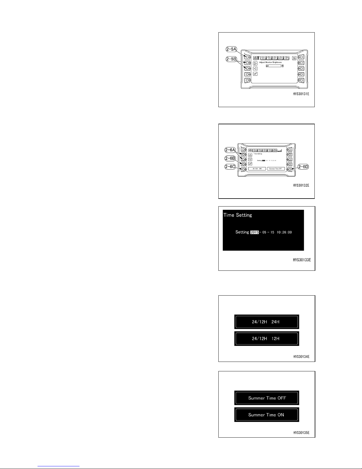
67
[2-5] MONITOR BRIGHTNESS ADJUSTMENT
When the switch (2-5) is pressed, the monitor brightness
can be adjusted.
Make adjustments with ◄ or ► of the adjustment switch
(2-5B).
The screen returns to the previous user mode screen with
the home switch (2-5A).
[2-6] TIME SETTING SCREEN
When the switch (2-6) is pressed, time setting, 24/12 hour
display and summer time ON/OFF can be changed.
• Time setting
• 24/12 hour display change
• Summer time ON/OFF
[2-6-1] TIME SETTING
Select the date and time desired to be changed with ◄ or
► of the adjustment switch (2-6A) and press the check
mark (2-6B).
(The part whose background is white is selected.)
When the word color turns red, editing becomes possible.
Make adjustments with ◄ or ► of the adjustment switch
(2-6A) in this condition.
When the check mark (2-6B) is finally pressed, editing is
completed.
[2-6-2] 24/12 HOUR DISPLAY CHANGE
When the switch (2-6C) is pressed, time display can be
changed to either 24 hour display or 12 hour display.
[2-6-3] SUMMER TIME ON/OFF
When the switch (2-6D) is pressed, ON or OFF of summer
time can be selected.
• ON: Time display is moved up by one hour.
• OFF: Originally set time is displayed.

68
[2-7] LANGUAGE SETTING
When the switch (2-7) is pressed, the language can be
changed if there are alternatives of the display language.
[2-8] ERROR HISTORY DISPLAY
When the switch (2-8) is pressed, the error history can be
viewed.
If a fault occurs now, it is displayed in red characters.
See "OPERATION 2.1.2 ‘’WARNING DISPLAY’’ for details.
[2-9] CONSUMABLES DISPLAY
When the switch (2-9) is pressed, the list of consumables
can be viewed.
After replacing a consumable item, use ▲ or ▼ of the
adjustment switch (2-9A) to select the replaced item. You
can also use the page selector switch (2-9D) to select the
required page.
Once you’ve selected a consumable item, hold down the
replacement switch (2-9B) and update the replacement
time. Once updated, the number of replacements is
incremented by 1, while the remaining time is reset.
NOTES
The message "Did you replace winch reduction gear?"
will appear when you replace the winch reduction gear
case oil. Select "Yes" or "No", as appropriate.
If the consumables icon display selector (2-9C) is set to
"Always" or "At start", the remaining time of 30 hours or 3
days will appear as yellow text with a white-on-dark icon
on the top screen, while the remaining time of 0 hours or 0
days will appear as red text with a red icon on the top
screen.
Replace these items promptly. Ignoring scheduled
replacements may generate hazards or adversely affect
the machinery.

69
NOTES
We recommend setting the consumables icon display
selector (2-9C) to "Always".
The consumables icon display changes as follows when
the replacement time approaches or when the
replacement time is exceeded based on the setting
made.
Always: The consumables icon is always displayed on
the top screen.
At start: The icon is disp
layed for just 30 seconds on
the top screen after startup.
No: The consumables icon is not displayed.
[2-10] SWITCH OPERATION SOUND ON/OFF CHANGE
When the switch (2-10) is pressed, switch operation sound
ON/OFF can be changed.
• OFF: The operation sound is disabled.
• ON: The operation sound is enabled.
[2-11] HOME SWITCH
• Short-time pressing :Returns one page.
• Long-time pressing :Returns to the top screen.
[2-12] DISPLAY PAGE CHANGE
Each time the switch is pressed, the page changes: "1/2
page to 2/2 page to 1/2 page".
[2-13] SOFTWARE VERSION CHECK
The controller software version can be checked.
[3] HOOK STORAGE SWITCH
•
The hook storage switch cancels the automatic stop function of the overwinding
prevention device.
When storing the hook block, carefully operate the right work equipment operation lever
and pay due attention not to allow the hook block to crash against the boom.
• Use the hook storage switch only when performing simple storage of the hook block in
the boom tip.
While continuing to press the switch (3), operate the right
work equipment operation lever toward the "Hoisting" side.
The hook block is hoisted and is stored in the storage section
of the boom tip.

70
When the switch is released, the automatic stop function of
the overwinding prevention device turns into an operating
state.
NOTES
・
While this switch is pressed, the red lamp of the rotating
warning lamp illuminates.
・
When the winch is hoisted while
this switch is pressed,
the hoisting speed becomes slow, which is not a fault.
[4] TRAVEL MODE SELECTOR SWITCH
Travel with a lifted load is in principle not advised because it is very unstable and involves
danger.
If travel with a lifted load is unavoidably performed, see "OPERATION 3.24 OPERATION
DURING TRAVELLING HOIST " and strictly observe the rated total load, operation method
and travel posture with a lifted load at the time of travel with a lifted load.
Unless these precautions in travell
ing with a lifted load are observed, serious physical
injury may be caused.
When the switch (4) is pressed, the mode can be changed
from the stationary mode to the travel mode enabling travel
with a lifted load.
The display of the machine body illustration on the top
screen changes.
[5] TRAVEL 1ST SPEED/2ND SPEED SELECTOR SWITCH
•
Be sure to perform loading to and unloading from a trailer at low speed ("set to 1st speed").
While travelling, never perform changing operation of the travel speed selector switch.
• If changing operation of high/low speed (2nd speed - 1st speed) i
s performed during
travelling, the travel direction may deviate even while travelling in a straight line. Perform
changing operation of travel speed after stopping the machine.
• The rear of the machine body is a blind spot. Be sure to check the rear of the machine
body with a rear view camera before performing backward travel operation.

71
The switch (5) changes the travel speed into two stages.
Each time the switch is pressed, the speed changes from "1st
speed" to "2nd speed" to "1st speed" repeatedly.
• Display of monitor "1": Low speed travel (1st speed)
• Display of monitor "2": High speed travel (2nd speed)
The display (12) on the top screen changes.
NOTES
・
When the actual load value of the moment lim iter is 0.5ton or more, the mach ine does n ot t ravel
at high speed even if "2" is displayed on the monitor.
[6] FUEL GAUGE
The meter (6) indicates the fuel quantity in the fuel tank.
When the indicator comes near the red color of the meter,
check the fuel quantity in the fuel tank and replenish fuel.
NOTES
Although the indicator may not point to the correct position
for a while after the starter switch is turned "ON", this is
normal.
[7] CLO CK DISPL AY
Displays the time.
[8] HOUR METER DISPLAY
Displays the hour meter.
[9] WORKING MODE DISPL AY
Displays the working mode currently set.
[10] AUTO DECELERATION DISPLAY
This is displayed when Auto deceleration is ON.
[11] WINCH 1ST SPEED/2ND SPEED DISPL AY
Each time the winch 1st speed/2nd speed selector switch is pressed, the speed changes "from 1 to
2 to 1".
[12] TRAVEL 1ST SPEED/2ND SPEED DISPLAY
Each time the travel 1st speed/2nd speed selector switch is pressed, the speed changes "from 1 to
2 to 1".
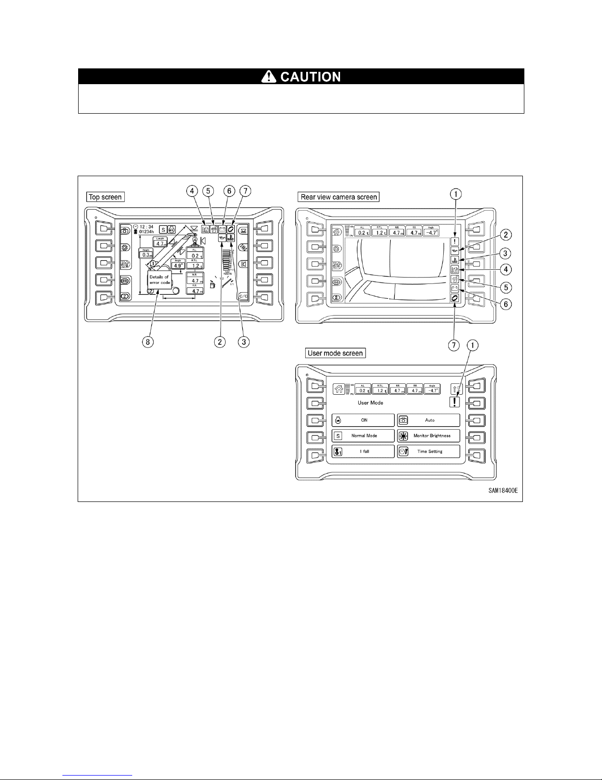
72
2.1.2 WARNING DISPLAY
[1] WARNING DISPLAY AND ERROR CODE DISPLAY
If the warning monitor illuminates in red, immediately stop the work and stop the engine or
set it to low idle. Then, immediately inspect the applicable part and take the correct action.
Emergency stop items are those to which you have to pay attention during engine running and when
an abnormality occurs, items for which immediate action must be taken are displayed. When an
abnormality occurs, the monitor of the abnormal part illuminates in red and the buzzer sounds.
(1) Abnormality display (abnormality detected)
(2) Engine oil pressure abnormality
(3) Engine coolant temperature abnormality
(4) Hydraulic oil temperature abnormality
(5) Fuel clogging abnormality
(6) Charged capacity display
(7) Consumables display
(8) Error code display
If a warning and/or error code is displayed, check the warning content and error content.
If an error code is displayed, please contact us or our sales and service agency.

73
[2] LIST OF ERROR CODES
If the following error codes are displayed, see "Operation 8. Action in the case of abnormality”. If you think
there is another reason, ask us or our sales service agency for repair.

74
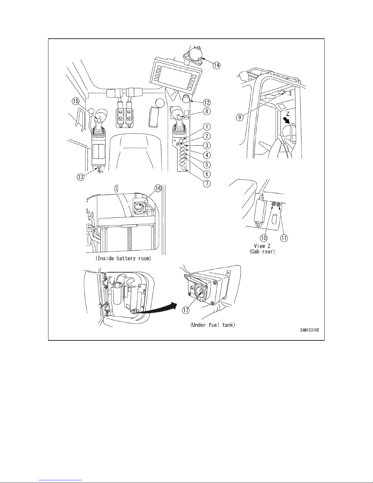
75
2.2 SWITCHES
(1) Starter switch
(2) Fuel adjustment dial
(3) Lamp switch
(4) Front window wiper switch
(5) Roof window wiper switch
(6) Buzzer canceling switch
(7) Accessory power supply
(8) Horn switch
(9) Room lamp switch
(10) Emergency accelerator driving switch (with
guard)
(11) Slewing parking brake emergency canceling
switch (with guard)
(12) Emergency stop switch
(13) Maintenance switch
(14) Levelling instrument
(15) Winch 2 speed selector switch
(16) Disconnect switch
(17) Override switch
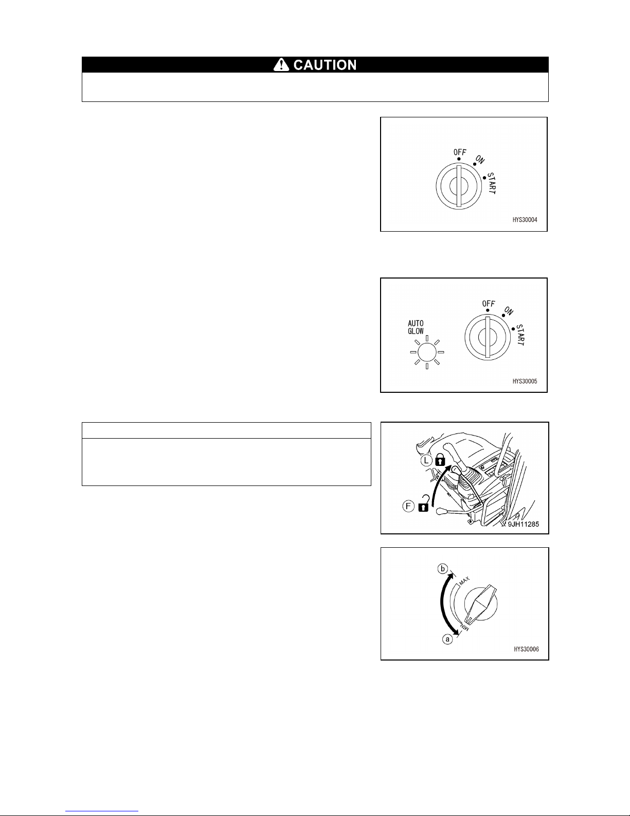
76
[1] STARTER SWITCH
Always turn the starter switch to the “OFF” position at the end of work.
Use this switch to start and stop the engine.
• OFF
The key can be inserted and removed, the electrical
system current is turned off except the room lamp and the
engine stops.
• ON
Electricity flows through the charging circuit and lamp
circuit. Keep the switch at this position while the engine
is running.
• START
A position where the engine starts. Keep the key at this
position during cranking and when the engine has started,
immediately release your hand from the key. The key
automatically returns to the “ON” position.
The engine of this machine has the automatic remaining
heat function. If the engine does not crank when it is cold,
AUTO GLOW lamp illuminates. When the lamp
illuminates, wait until the lamp goes out and then, turn the
switch to the START position to start the engine.
NOTES
The engine does not start unless the lock lever is at the lock
(L) position.
Check that the lock lever is at the lock (L)
position before operating the starter switch.
[2] FUEL ADJUSTMENT DIAL
Adjusts the engine speed and output.
• (a) Low idling (MIN): Position where the dial is fully
turned counterclockwise (left
direction)
• (b) Full revolution (MAX): Position where the dial is
turned clockwise (right
direction)

77
[3] LAMP SWITCH
Use this switch to turn on the working lamp and headlamps.
• (a) ON position: The lamp turns on.
• (b) OFF position: The lamp turns off.
[4] FRONT WINDOW WIPER SWITCH
Use this switch to activate the wiper of the cab front window
and window washer fluid.
• (a) Wiper position: The wiper operates.
• (b) Washer position:
When the switch continues to be pressed, washer
fluid is emitted and the wiper operates.
When you release your hand from the switch, the
switch returns, washer fluid stops and the wiper also
stops.
• (c) Stop position: The wiper stops.
[5] ROOF WINDOW WIPER SWITCH
Use this switch to activate the wiper of the cab roof. window
and window washer fluid.
• (a) Wiper position: The wiper operates.
• (b) Washer position:
When the switch continues to be pressed, washer
fluid is emitted and the wiper operates.
When you release your hand from the switch, the
switch returns, washer fluid stops and the wiper also
stops.
• (c) Stop position: The wiper stops.
[6] BUZZER CANCELING SWITCH
For your safety, set the switch to the normal position for
work.
• (a) Cancel position:
The warning buzzer sound is stopped.
• (b) Normal position:
The warning buzzer tone sounds.
NOTES
The buzzer tone which can be cancelled is limited to the
buzzer tone
when a fault code is displayed.Other warning
sounds are not cancelled.
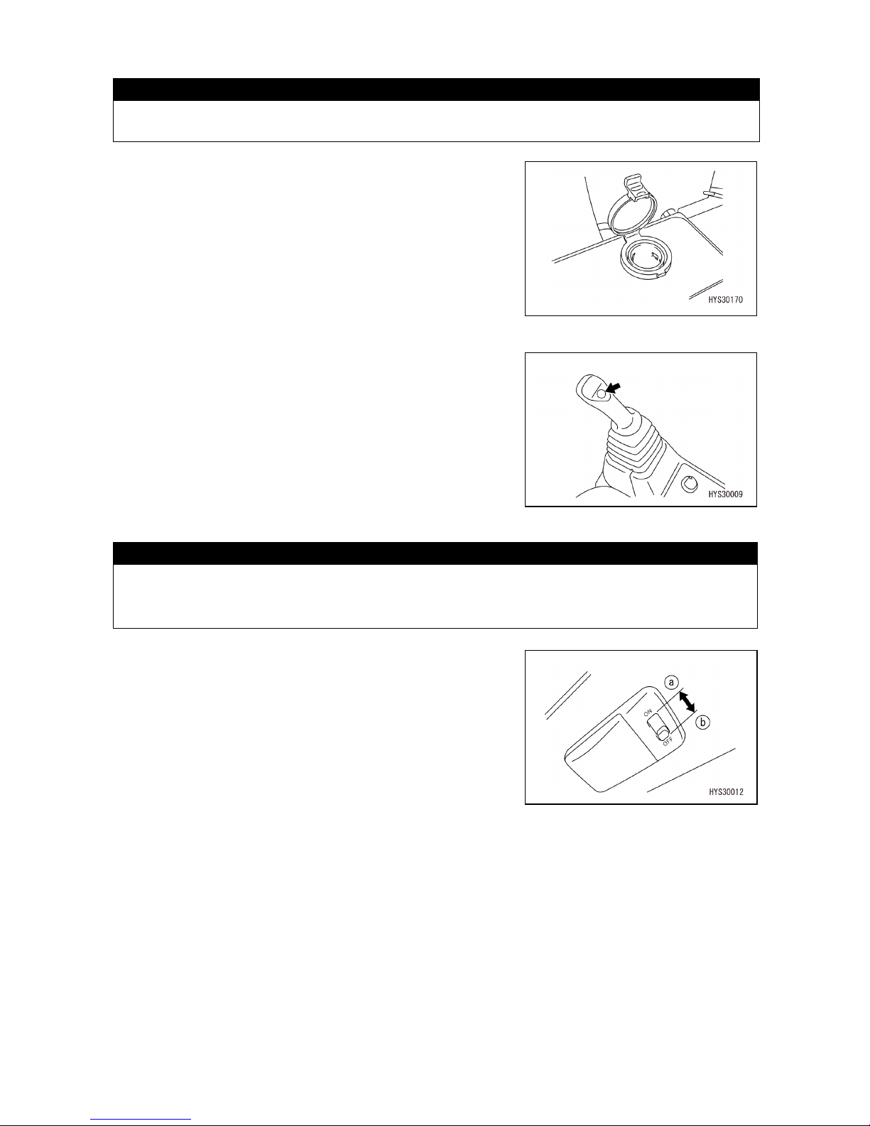
78
[7] ACCESSORY POWER SUPPLY
CAUTION
Accessory power supply is for 24V. Do not use this as power supply for equipment of 12V.
This can be used as an accessory socket.(100W (24V x
5A))
[8] HORN SWITCH
Use this switch to honk the horn.
When the switch on the knob part of the right work
equipment operation lever is pressed, the horn honks.
[9] ROOM LAMP SWITCH
CAUTION
Failure to turn off the switch causes the battery to be discharged. Be sure to turn the switch
to the "OFF" position after using the room lamp. The room lamp turns on when the starter
switch is at the "OFF" position.
Use this switch to turn on the room lamp.
• (a) "ON" position: The room lamp turns on.
• (b) "OFF“ position: The room lamp turns off.
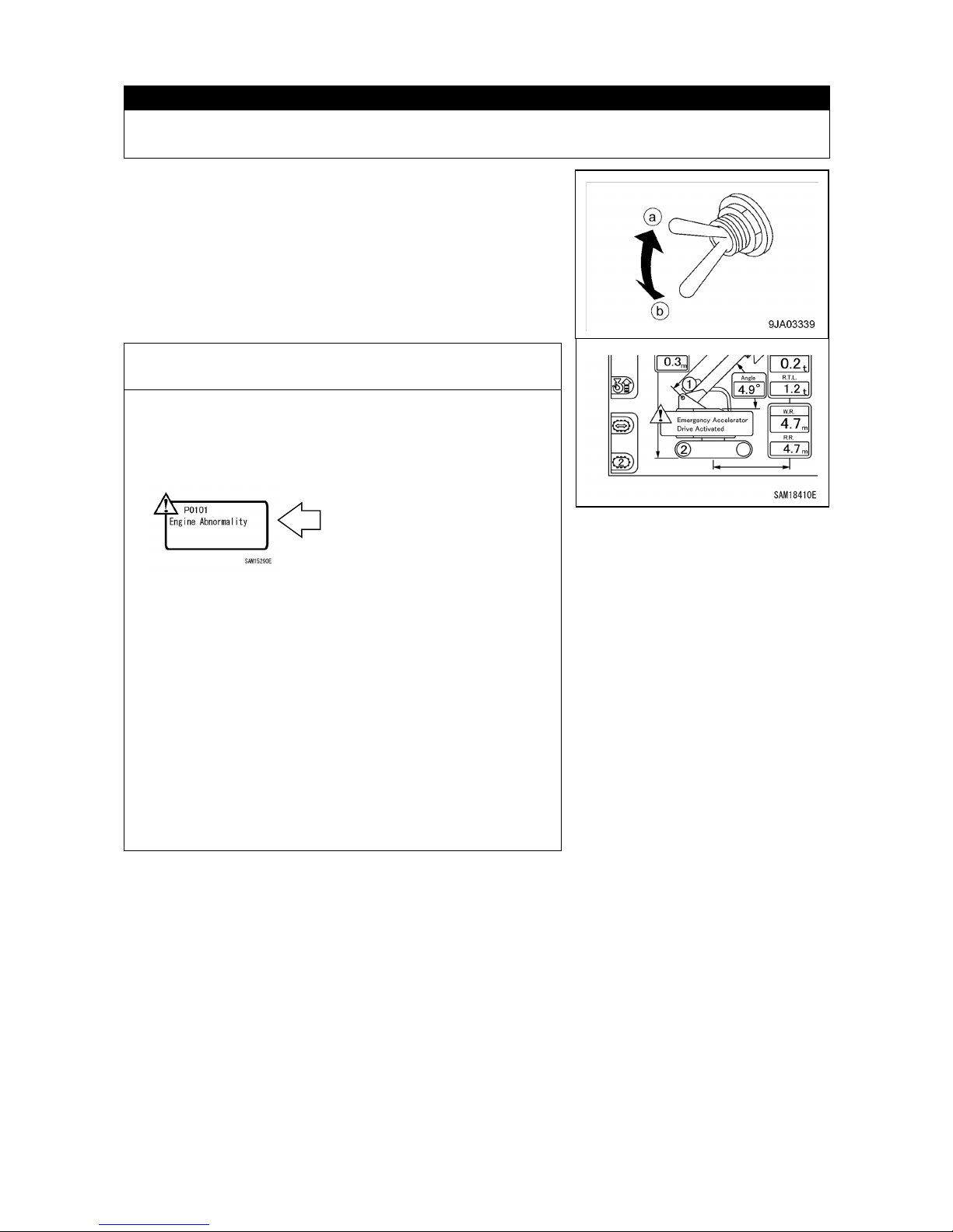
79
[10] EMERGENCY ACCELERATOR DRIVING SWITCH
CAUTION
Use this switch to increase the engine speed temporarily when accelerator revolution does
not increase because of an abnormality in the electrical system.
Use this switch to perform work temporarily when an
abnormality occurs in the accelerator control system.
• (a) "Emergency" position: Abnormal case (switch raising)
+ buzzer sounding and display
on the monitor
• (b) "Normal" position: Normal case (switch lowering)
NOTES
When the switch is turned to the (a) "Emergency" position in
the normal case, the engine abnormality (P0101) error is
displayed on the monitor even if the switch is returned to the
(b) "Normal" position. However, this is not a fault.
In this case, take the following steps to delete the error
display.
1. Turn the switch to the (b) "Normal" position.
2. Start the engine and operate it at least for one minute.
3. Turn OFF the starter switch and stop the engine at least
for one minute.
4. Repeat the steps 2 and 3 again.(Twice each in total)
5.
When the above operation is performed, the engine
abnormality (P0101) display on the monitor
disappears.
If these steps fail to clear the error, contact us or our sales
service agency.
Error displayed on the
monitor
(Not a fault)
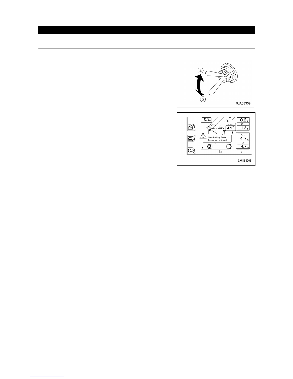
80
[11] SLEWING PARKING BRAKE EMERGENCY CANCELING SWITCH
CAUTION
This enables slewing operation temporarily when the controller is abnormal. Do not use
this switch except in the abnormal case. Promptly repair the abnormal area.
Use this switch to perform slewing operation temporarily
when an abnormality occurs.
• (a) "Release" position: Abnormal case (switch raising) +
buzzer sounding and display on
the monitor
• (b) "Normal" position: Normal case (switch lowering)
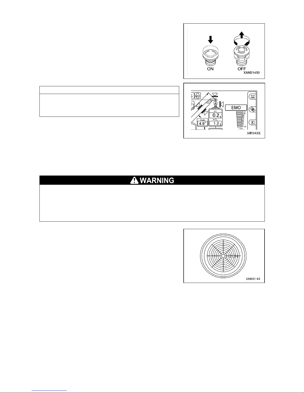
81
[12] EMERGENCY STOP SWITCH
Use this switch to stop the engine urgently.
• ON: Press the switch. The engine stops.
"Emergency stop" is displayed on the upper right of the
monitor.
• OFF: Turn the switch clockwise (in the arrow direction on the
right illustration).
The switch returns to the original position.
NOTES
When restarting the engine after an emergency stop, be
sure to turn the EMO switch to the “OFF
” position before
starting the engine.
[13] MAINTENANCE SWITCH
This switch is not used for crane operations.
It is a maintenance switch for servicing.
[14] LEVELLING INSTRUMENT
If crane operation is performed with the machine tilted, it may cause tripping.
Find a place, whilst looking at the levelling instrument, where the machine body is in a level
state before starting crane operation.
If work is unavoidably performed on a slope, place planking or lay earth on the ground to
make the ground level.
This displays an inclination status of the machine.
The inclination and direction of the machine can be
determined from the position of the air bubbles.
Use this to check whether the machine body is in a level
condition.

82
[15] WINCH 2 SPEED SELECTOR SWITCH
• Perform raising and lowering operation at high speed only under a no load condition and
without hoisting a load.
Raising and lowering operation of a hoisted load at high speed may cause serious
physical injury due to the machine tipping, breakage or dropping of a load.
• If the weight of a hoisted load is "0.5t" or more, the speed does not become high even
when the winch 2 speed selector switch is operated.
If the weight of a hoisted load is "0.2
t" or less, it is possible to perform raising and
lowering operation in high, but such operation may cause serious physical injury due to
machine tipping, breakage or dropping of a load. Therefore, avoid such operation as much
as possible.
Use this switch when changing the speed at the time of
raising and lowering operation of the winch.
The lever switch can change the speed between "1st
speed" and "2nd speed".
• High speed (2nd speed): Raising and lowering speed is
increased.
• Low speed (1st speed): The speed returns to the normal
raising and lowering speed.
Check that when the lever switch is pressed, the monitor
display also changes.
NOTES
When the number of wire falls of the moment limiter is set to
"one fall", the speed does not become high even if this
switch is placed in the "High speed (2nd speed)" position.
The speed is fixed to "Low speed (1st speed)".
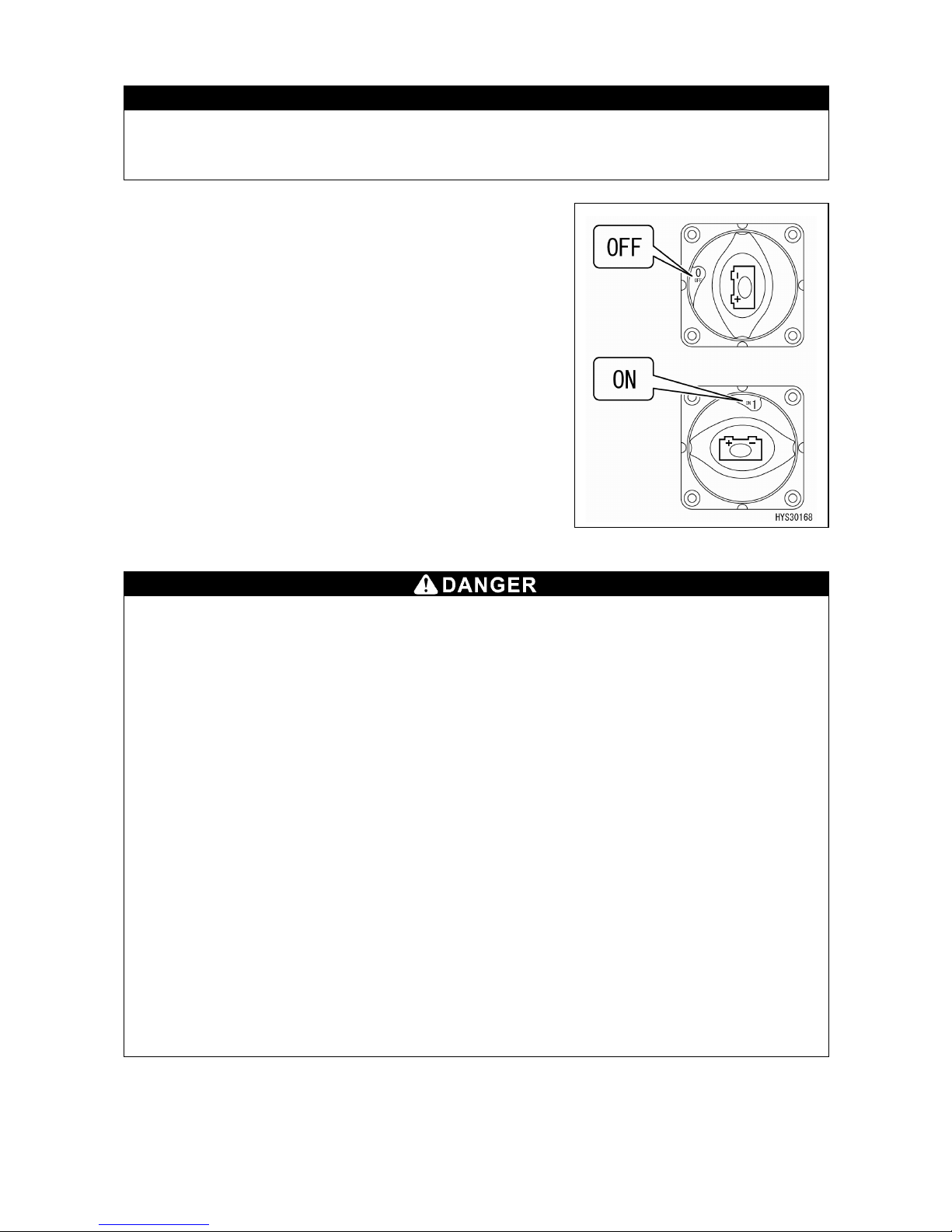
83
[16] DISCONNECT SWITCH
CAUTION
Be sure to place this switch in the "ON" position. Use this switch temporarily only in the
case of preventing unexpected startup of electrical equipment during inspection and
maintenance.
Use this switch to turn off the battery power supply to prevent
unexpected startup of electrical equipment during inspection
and maintenance.
• OFF: The battery power supply is turned off and no
electricity flows through all the electrical systems.
• ON: The battery power supply is connected.
[17] OVERRIDE SWITCH
Override switch has a function to disable the moment limiter.
When this switch is turned ON, the crane does not automatically stop with the moment
limiter and is very dangerous. Any crane operation in such conditions may
result in
dropping of hoisted load, breakage of crane boom, and/or machine tipping, and may cause
a serious accident resulting in death or serious injury.
Use this switch only when the moment limiter, which detects the crane conditions, fails or
a load test of the crane is conducted. Key for the switch must be detached during normal
operations.
In particular, never perform the following uses.
• Never wind up the hook when hoisting loads.
Even if the weight of hoisted load exceeds the rated total load, the moment limiter cannot
detect it, and could result in dropping of the hoisted load, boom breakage or machine
tipping due to cutting of the winch wire rope.
•
After the moment limiter detects that the rated total load is exceeded during crane
operation and automatically stops the operation, do not perform hoisting operation, boom
lowering operation and boom extension operation while the operation stop function is
cancelled by turning this switch to the "ON" position. Such operation may cause boom
breakage and machine tipping.
• Use the hook storage switch when storing the hook. If this switch is turned ON to perform
hook hoisting operation, automatic stop is not made in an over winding condition.

84
Use this switch only when the moment limiter fails or a load
test of the crane is conducted.
• ON: Insert the key into the switch. Turn the key clockwise
and then return it to the original position. The key
automatically returns to the "OFF" position when you
release your hand.
The operation stop function is cancelled for 10 minutes
after it is turned ON.
• OFF: The key can be removed or inserted at this position.
NOTES
You will notice the following when the operation stop
function is cancelled.
• The red lamp of the rotating warning lamp turns on.
• The LED of the switch box lights up.
• The buzzer sounds continuously.
• The icon will be displayed on the monitor.
[Overriding / Turn stater key off to reset]
The above statuses will change as follows 30 seconds
before the operation stop fuction returns from the cancelled
state.
• The LED of the switch box blinks.
• The buzzer additionally emits intermittent sound.
• Another icon will be displayed additionally on the monitor.
[Stop operation / Overriding soon stops]
However, these behaviors are subject to change depending
on the status of the Machine body.
Although the boom lowering and extending operations slow
down when the operation stop fuction is cancelled, this is
normal.
By turning the engine key OFF, the Machine can be
restarted even before 10 minutes have passed.

85
2.3 OPERATION LEVERS AND PEDALS
(1) Lock lever
(2) Travel lever (with auto deceleration
mechanism)
(3) Left work equipment operation lever (with auto
deceleration mechanism)
(4) Right work equipment operation lever (with
auto deceleration mechanism)
(5) Accelerator pedal
[1] LOCK LEVER
•
When standing up from the driver seat, place the lock lever securely in the lock position
(L). If the lock l
ever is in the free position (F) and contacts the operation levers and
operation pedals carelessly, serious physical injury may be caused.
• When you leave the driver seat or work is suspended, check that the lock lever is securely
in the lock position (L).
• When pulling up or pushing down the lock lever, be careful not to allow it to contact the
operation lever of work equipment.

86
Use this lever to lock crane operation, slewing and travel
operation.
• (L) Lock: Pull up the lever. The machine does not move even
if each operation lever is operated.
• (F) Free: Push down the lever. The machine moves if
each operation lever is operated.
NOTES
Because the machine is hydraulically locked by the lock
lever, operation levers move even
if the lever is placed in
the lock position. However, the machine does not move.
[2] TRAVEL LEVER
•
When the sprocket (A) side is in the rear, the track
frame faces forward.
When the track frame faces
rearward, the direction of travel lever
operation is
opposite to the direction of machine movement
(forward and rearward movement, right and left
movement direction).
When operating the travel lever, be sure to check if
the track frame faces forward or rearward.
Use this lever to move the machine forward/rearward, stop,
change the direction, and adjust the travelling speed.
• (a) Forward movement: Push the lever forward.
• (b) Rearward movement: Pull the lever toward you.
• (N) Neutral: Release your hand from the lever.
NOTES
When the travel lever is operated to the forward or rearward
direction
from neutral, the alarm sounds and notifies the
surrounding area that the machine will start moving.

87
[3] WORK EQUIPMENT OPERATION LEVER
• The operation pattern is set according to the standard operation method (ISO pattern).
If you desire to change the operation pattern, please request us or our sales service
agency.
• When the operation pattern is changed, the operation nameplate needs to be replaced
with one that matches the machine movement.
(1) Left work equipment operation lever
Use this lever to perform slewing operation of the revolving
super structure and extension and retraction operation of
the boom.
Slewing operation
• (a) Right slewing: Pull the lever in the right direction.
• (b) Left slewing: Push the lever in the left direction.
Extension and retraction operation of boom
• (c) Retraction of boom: Pull the lever rearward.
• (d) Extension of boom: Push the lever forward.
(N) Neutral: Release your hand from the lever.
The revolving upper structure and boom length retain their positions as they stop.
(2) Right work equipment operation lever
Use this lever to perform winch operation and boom
derricking operation.
Winch operation
• (e) Hoisting: Pull the lever rearward.
• (f) Lowering: Push the lever forward.
Boom derricking operation
• (g) Lowering of boom: Push the lever in the right direction.
• (h) Raising of boom: Pull the lever in the left direction.
(N) Neutral: Release your hand from the lever.
The hook block and boom angle retain their positions as they stop.
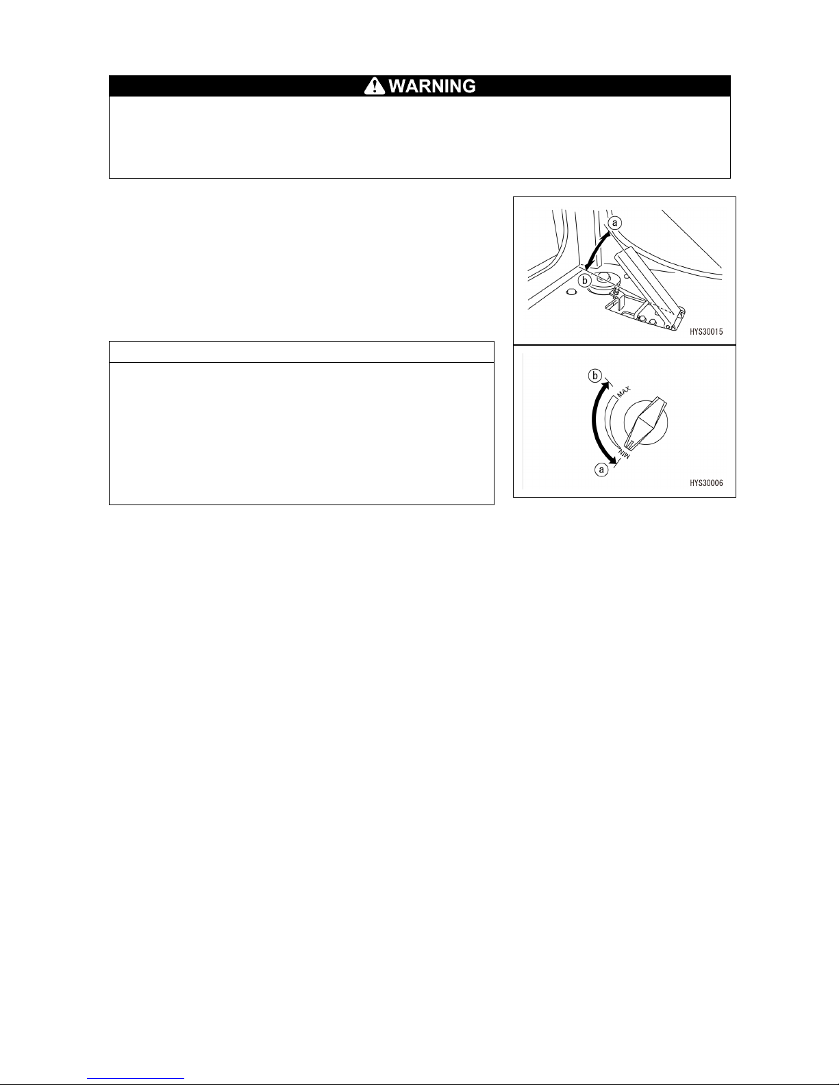
88
[4] ACCELERATOR PEDAL
Use the accelerator pedal only when the machine stops and you operate the crane.
Never use this pedal during travel operation. An operation mistake may be made, resulting
in serious physical injury.
Use the fuel adjustment dial to adjust engine speed during travel operation.
Use this lever to adjust the engine speed or output during
crane operation.
• (a) Low idling: Release your foot from the pedal.
• (b) Full revolution: Depress the pedal fully.
NOTES
As a priority is given to the engine speed of the fuel
adjustment dial, the engine speed does not fall below the
set speed of the fuel adjustment dial even if you release your
fool from the accelerator pedal.
When performing work using the accelerator pedal, operate
the fuel adjustment dial in advance to set the necessary
minimum engine speed.
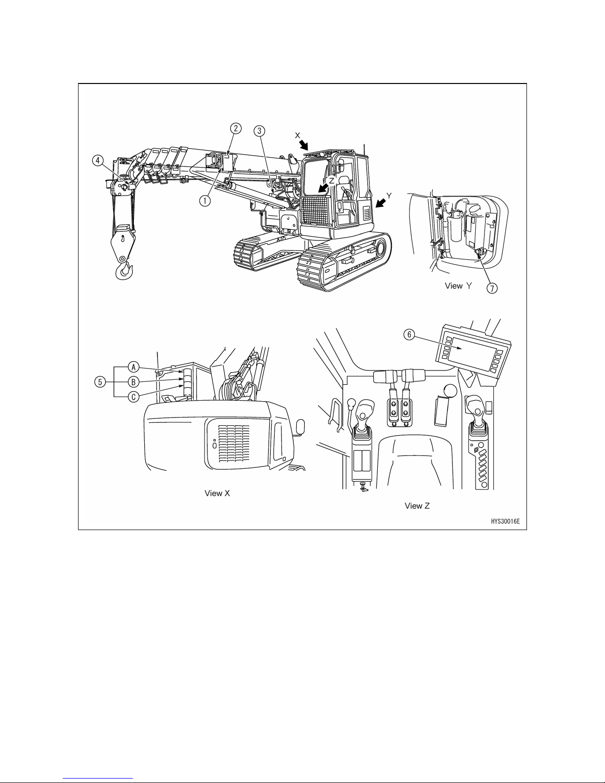
89
2.4 MOMENT LIMITER (OVERLOAD PREVENTIVE DEVICE)
2.4.1 CONFIGURATION OF MOMENT LIMITER
(1) Boom length meter (left side of boom)
(2) Boom angle meter (left side of boom)
(3) Pressure sensor (derricking cylinder section) (2 pieces)
(4) Overwinding detector (side of boom tip)
(5) Rotating warning lamp
(A) Rotating red lamp (warning lamp when load factor is 100% or more)
(B) Rotating yellow lamp (prediction lamp when load factor is 90 - less than 100%)
(C) Rotating green lamp (operation lamp when load factor is less than 90%)
(6) Machine monitor (moment limiter display section) (inside cab)
(7) Override switch
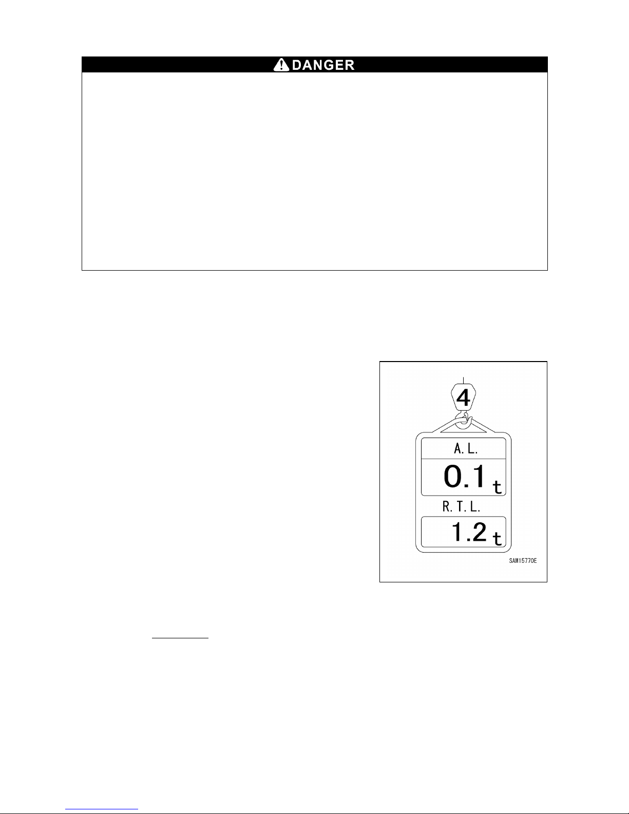
90
2.4.2 FUNCTIONS OF MOMENT LIMITER
• Do not remove, disassemble, or repair the detector. In
addition, do not reposition the
detector from the original location to another.
• When an object hits the detector or damage is found on it, be sure to check the operating
condition of the automatic stop.
If any abnormality is found in the operation condition of automatic stop, be sure to repair
it.
• The slewing operation does not stop automatically when the crane is overloaded. When
overloaded, do not perform slewing operation.
• When the crane is ap
proximating the stop position during boom operation, be sure to
lower the boom operation speed.
If the boom is at a high operation speed, it may exceed the predetermined stop position
and the machine may tip over causing severe personal injury, which could lead to death
or serious injury.
The moment limiter is a device that is installed to prevent dropping of the suspended load or
breakage or tipping of the machine, which may occur due to overload.
Before starting crane operations, be sure to inspect operation of the moment limiter to make sure
that there is no abnormality.
[1] MECHANISM OF MOMENT LIMITER
The moment limiter knows the current posture by the boom
angle meter and boom length meter and calculates "Rated
total load" in the current condition by further knowing the
number of wire falls (input by a driver).
When the load is hoisted actually at this time, the moment
limiter calculates the "actual load" (hoisted load) according to
the pressure value from the pressure sensor of the derricking
cylinder section. The moment limiter makes comparison and
calculation on "Rated total load" and "Actual load" (hoisted
load) that were calculated in the current figure. Then, it issues
an alarm if the result is as follows: "Actual load / Rated total
load = 90 to 100%".
If the calculation result is "Actual load / Rated total load =
100% or more", the moment limiter issues an alarm and at the
same time automatically stops the boom operation.
The overload stop accuracy satisfies the stop accuracy of the
following formula by slowly lowering the boom.
Stop
accuracy =
A - B
×100<+10%
B
Where, A: Total weight of suspended load + hook + hoisting attachment (Slings etc)
B: Rated total load of working radius (actually measured radius) where the boom stopped
due to overload

91
[2] MOMENT LIMITER ABNORMALITY OCCURRENCE MESSAGE DISPLAY
The moment limiter displays a fault code on the top screen of the monitor to notify the driver if an
abnormality occurs in the boom angle meter, boom length meter or pressure sensor, or if wiring is
cut or connectors come off.
If a moment limiter related fault code is displayed on the monitor, immediately stop the use of the
crane.
For the fault code and cause and action for the abnormality, see "OPERATION 2.1.2 [2] LIST OF
ERROR CODES".
2.4.3 MOMENT LIMITER OPERATION AND CANCELING (RECOVERY)
The moment limiter is a device that is provided for measures available for an emergency case. In
actuality, any operations relying on the device will incur danger.
Operate the crane carefully so that it does not stop automatically.
[1] PROHIBITED OPERATIONS AFTER AUTOMATIC STOP
The following crane operation is prohibited after the crane stops automatically due to
overload.
Disobeying this rule may cause critical danger due to tipping of the machine or breakage of
the boom, for example.
• Boom lowering operation • Boom hoisting operation • Boom extending operation
• Hook hoisting operation
[2] RECOVERY OPERATION FROM AUTOMATIC STOP
If an automatic stop occurs, you will not be able to clear the stop until you have reduced the
load factor to the safety area with a load factor of less than 90% (rotating warning lamp:
green).
If the moment limiter displays the load factor of 90% or more, be sure to perform crane
operations carefully by turning the engine speed to low.
Performing crane operations at a high engine speed could cause critical danger; in this
case, the hoisted load will waggle resulting in overload, which could lead to tipping of the
machine or breakage of the crane, for example.
1. When load factor is "less than 90%"
When the hoisted load is less than 90% of the rated total load,
the green color of the rotating warning lamp which shows a
normal use condition turns on.
2. When load factor is "90% - less than 100%"
When the hoisted load is 90% (prediction alarm) of the rated
total load, the rotating warning lamp changes from the green
color to the yellow color and the alarm sounds to notify the
driver and persons in the surrounding area that the hoisted
load approaches the rated total load.
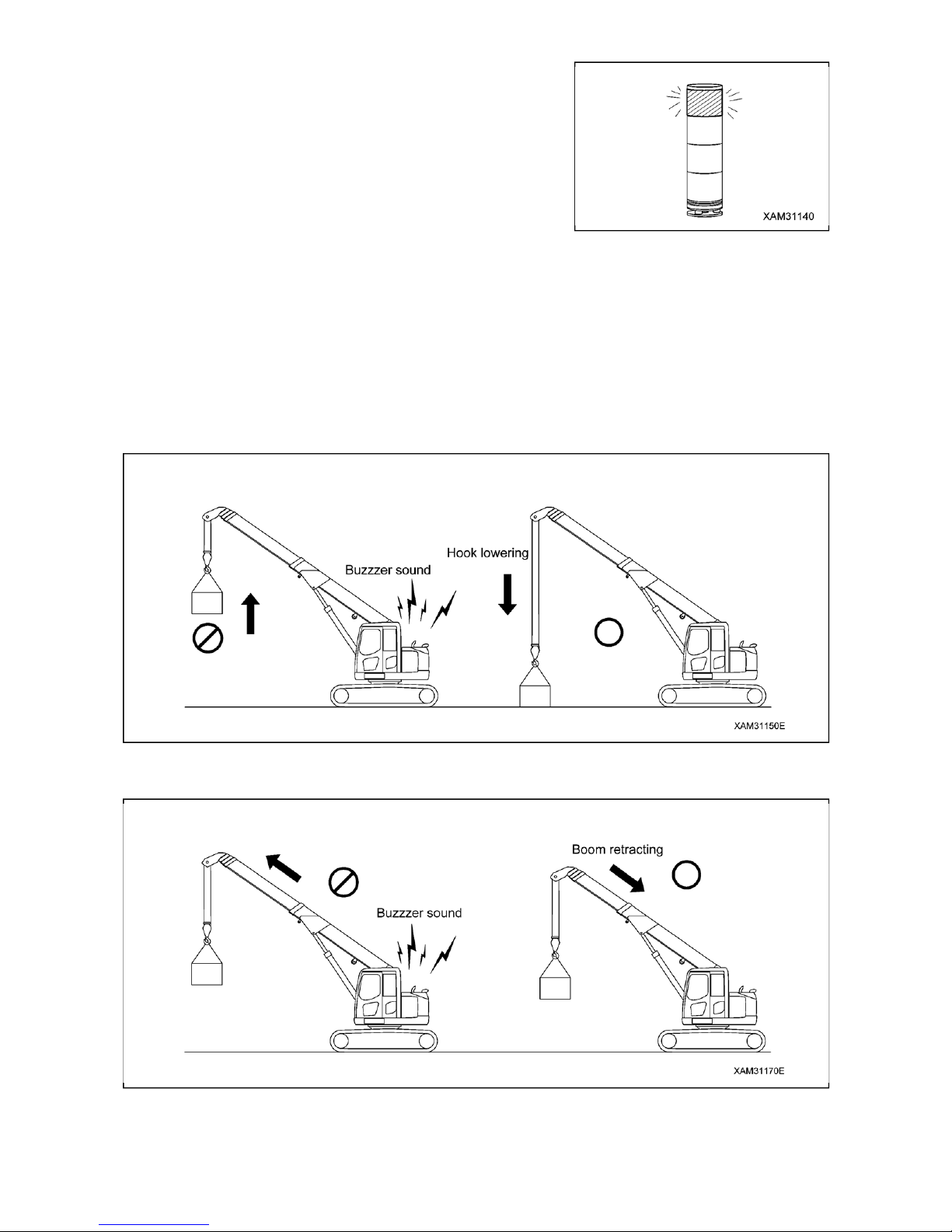
92
3. When load factor is "100% or more"
If the hoisted load exceeds 90% (prediction alarm) of the
rated total load and the hoisted load becomes 100% or more
of the rated total load by further continuing crane operations,
the rotating warning lamp changes from the yellow color to
the red color, the alarm sounds continuously and subsequent
crane action stops automatically.
• Hook hoisting action • Boom extending action
• Boom lowering action • Boom hoisting action
In addition, audible warning "Peep, overload" is issued.
4. RECOVERY OPERATION FROM AUTOMATIC STOP
To perform recovery operation from overload, perform either of the following operations so that the
crane action will be opposite to the one when the crane stopped automatically.
Note that the automatic stop cannot be cleared unless the load factor has first been lowered to the
safety area with a load factor of less than 90% (rotating warning lamp: green).
(1) Perform hook lowering operation to put down the hoisted load.
(2) Perform boom retraction operation.
 Loading...