

Page 1
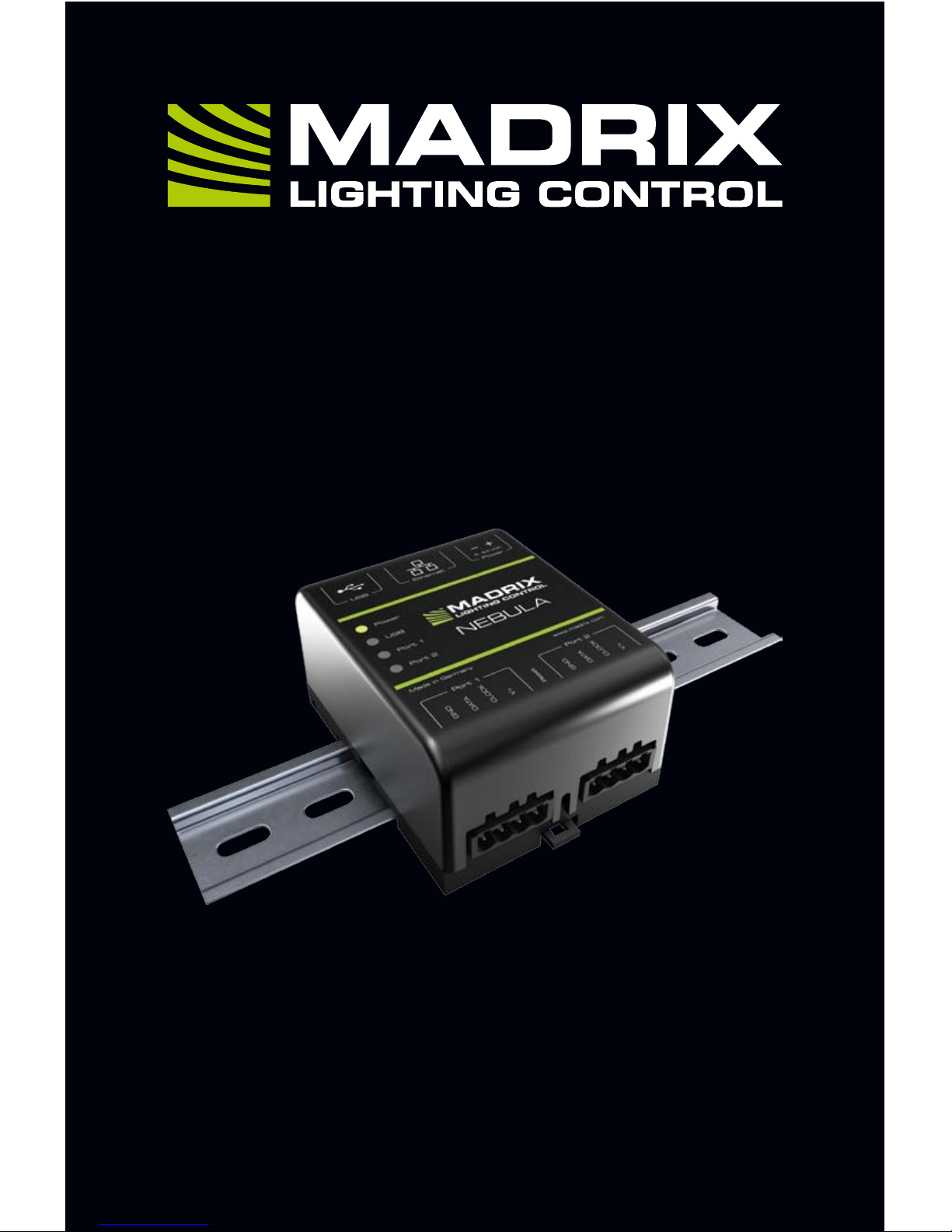
NEBULA
Quick Start Guide & Technical Manual
Page 2

1 EN
MADRIX® NEBULA –
Quick Start Guide & Technical Manual
3rd Edition – September 2017
Thank you for purchasing MADRIX
®
NEBULA!
Please read this guide carefully and thoroughly before using MADRIX®
NEBULA. Make sure that you fully understand all information.
This MADRIX® NEBULA Quick Start Guide is written in English and German.
(Diese Kurzanleitung wurde in englischer und deutscher Sprache verfasst.)
Developed and made in Germany.
Imprint
inoage GmbH
Wiener Straße 56
01219 Dresden
Germany
Managing Directors: Christian Hertel, Sebastian Pinzer, Sebastian Wissmann
Page 3
EN 2
English
Copyright Information And Disclaimer
© 2017 inoage GmbH. All rights reserved. Information is subject to change at
any time and without prior notice. Errors and omissions excepted. Reproduction,
adaptation, or translation without prior written permission is prohibited.
inoage GmbH does not grant guarantee on validity for a particular reason, the
marketability, or other properties of the product. There is no way to assert a
claim to inoage GmbH, neither in the legal way nor in other ways. inoage GmbH
is not responsible for damages, including all disadvantages that are not just
limited to the loss of sales, but that are caused due to the use of the product,
due to the loss of serviceability of the product, due to misuse, happenings,
circumstances, or actions that inoage GmbH does not have influence on, no
matter if the damages as well as consequential damages are direct or indirect;
whether they are special damages or others, nor if the damage is caused by the
owner of the warranty or a third person.
Trademark Credits
Microsoft® and Windows® are U.S. registered trademarks of Microsoft
Corporation. Art-Net™ – Designed by and Copyright Artistic Licence Holdings
Ltd. All other products mentioned herein may be trademarks of their respective
companies. MADRIX® is a registered trademark of inoage GmbH.
Package Contents
1x MADRIX® NEBULA
1x Set of screw terminals (2x 4-pin and 1x 2-pin)
1x USB 2.0 cable
(certified)
2x Wall-mount brackets
1x Quick start guide
Please note: Check the package contents and the condition of the interface
after unpacking! Contact your supplier if something is missing or damaged. Do
not use the device if it seems to be damaged!
Page 4
3 EN
Safety Instructions And Limited Warranty
Two years of limited manufacturer’s warranty are granted to the purchaser
of this product. Warranty applies to constructional fault, material defect, or
incorrect assembly the manufacturer has caused or is to be held responsible
for. Warranty will be void if the interface is opened, modified, damaged through
inappropriate handling and wrong usage, damaged through overvoltage, or
damaged through any other cause.
Please follow the instructions below to avoid mishandling, damage to the
device, or personal injury:
THE DEVICE WORKS WITH LOW VOLTAGE (DC 5 V – 24 V).
DO NOT USE ANY OTHER VOLTAGE!
Beware that the interface works with electrical power. Only use the
device in dry environments (indoor use). The IP Rating of the device
is IP20. Do not use the interface in humid environments and avoid
contact with water or any other liquids. Turn off the power if you are not using
the device for a long time.
Avoid unwanted voltage on the cables at all times. Do not remove any parts
from the unit or connect to an ungrounded circuit. Do not connect the unit to
LEDs that are switched on. Only connect the unit to LEDs and controllers that
are initially powered off.
There are no user serviceable parts inside or outside the interface. Repair
service lies only within the responsibilities of the manufacturer. If the interface
appears to be defective, please contact your dealer. After expiration of the
warranty period you may contact your supplier or the manufacturer to have the
unit repaired against payment of an individual service fee if possible.
The interface has several ports and slots. Only connect or insert devices,
cables, and connectors to the individual ports and slots using connectors of the
same type as the port. Do not use inapplicable equipment. This device should
be used by professionals. The device is not designed to be operated by nonprofessionals or children.
▴
!
Page 5

EN 4
English
End-Of-Life
This electrical device and its accessories need to be disposed of
properly. Do not throw the device into normal trash or household
waste. Please recycle packaging material whenever possible.
Usage
In general, this device is designed to receive control data over Ethernet
(Art-Net) or USB and convert the data into supported SPI protocols. It is a
hardware interface to be connected towards various types of controllable,
digital LEDs. Do not use the interface for any other, deviating purpose. The
device can be connected to and disconnected from USB or Ethernet network
during use and without a reboot (Hot Swapping & Plug and Play). Multiple
interfaces can be used at the same time.
Technical Specifications
Power supply:
(See pages 7 – 13)
Power consumption:
Data output:
Ports:
Ethernet (Art-Net):
USB port:
Case:
Dimensions:
Weight:
Temperature range:
Relative humidity:
Supported LEDs:
(As of September 2017 –
see www.madrix.com
for the latest information)
DC 5 V – 24 V, A) via 2-pin screw terminal (12 A max.),
B) via 5 V USB, C) via Port 1 or 2 sourced from LEDs;
6 A max. load per port when supplying through to LEDs
< 1.5 W during normal operation (300 mA max.)
8x 512 channels SPI TTL (Maximum output per port:
680 RGB LEDs / 512 RGBW LEDs / 2048 1-channel LEDs)
2x ports (via 2x 4-pin screw terminals)
RJ45, 10/100 MBit/s (compatible with 1 GBit/s)
USB 2.0, type B plug
Non-conductive, IP20, UL94 V-0 flammability rating,
designed for 35 mm DIN-rails or wall mounting
92 mm x 70 mm x 45 mm (length x width x height)
111 g | 130 g incl. screw terminals and wall mounts
-10 °C to 70 °C (Operating) | -20 °C to 85 °C (Storage)
5 % to 80 %, non-condensing (Operating / Storage)
APA101, APA102, APA104, APA106, GW6201, GW6205, LPD1882S, LPD6803,
LPD8806, MBI6120, P9883, SJ1221, SK6812, SK6822, SM16703, SM16716,
TLS3001, TLS3008, TM1804, TM1809, TM1812, TM1814, TM1829, UCS1903,
UCS512B3, WS2801, WS2803, WS2811, WS2811S, WS2812, WS2812B,
WS2813, WS2815, WS2818, WS2822S, WS2822S Addressing
Page 6
5 EN
IP Address And Other Device Information
You will find the following important information on the side of the device:
• Serial number (‘Serial’)
• Hardware revision (‘Model’)
• Default and preconfigured IP address (‘Default IP’)
(See page 15 to reset the device to the default IP address if needed.)
Using Any 3rd-Party Controller Via Art-Net
MADRIX® NEBULA is a standard Art-Net node. Because of this, you can use
the device with any application, console, or controller that supports Art-Net.
Using The MADRIX® Software
The MADRIX® Software is a professional and advanced LED lighting control tool.
It is recommended to use the MADRIX® Software in order to access all features
of MADRIX® NEBULA, including the USB connection, Art-Net, and Sync Mode.
MADRIX® Minimum System Requirements And
MADRIX® Supported Operating Systems
For the latest information, please check the website www.madrix.com
The minimum system requirements for the MADRIX® Software are as follows.
The optimal system specifications will often be higher.
• 2.0 GHz dual-core CPU, OpenGL 2.1 graphics card (NVIDIA recommended),
2 GB RAM, 1 GB free harddisk space, 1280 x 768 screen resolution,
network card, sound card, USB 2.0
The MADRIX® Software supports the following operating systems:
• Microsoft® Windows® 7 | 8 | 8.1 | 10
Please keep the system, drivers,
and updates up to date.
Please note: In order to distribute data via MADRIX® NEBULA using the
MADRIX® Software, a MADRIX® Software license is required (sold separately)!
Page 7
EN 6
English
Installing The MADRIX® Software And Drivers
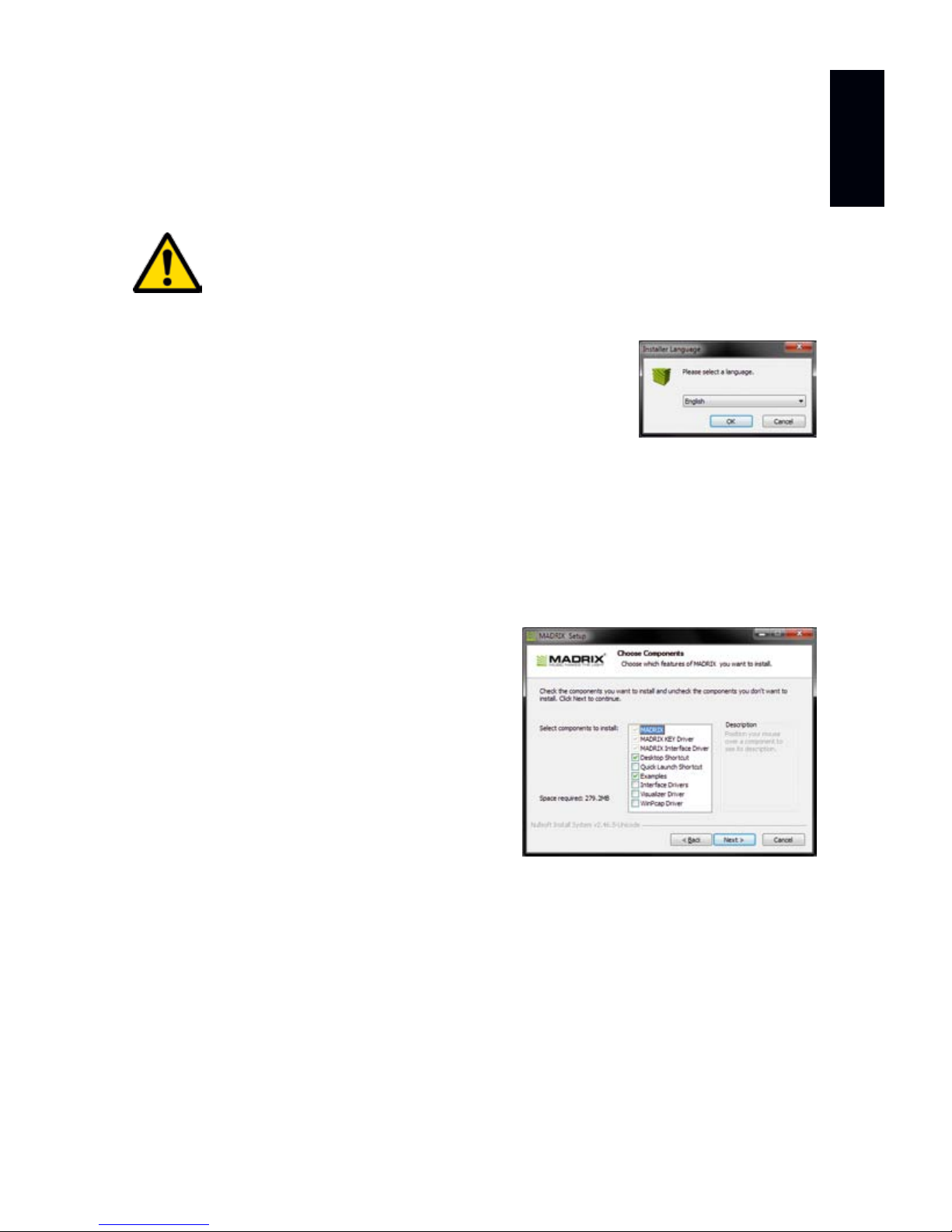
Start the installation process for the MADRIX® Software on your operational
computer via CD, USB flash drive, or downloaded software installer. Follow the
on-screen installation instructions as described below.
PLEASE INSTALL THE SOFTWARE AND DRIVERS
BEFORE YOU CONNECT MADRIX® NEBULA TO YOUR PC.
Second, the ‘Welcome’ window appears. Click ‘Next >’ to start the installation.
Third, the ‘License Agreement’ will be shown. It outlines the terms you are
agreeing to when you install the software. You must accept these terms in
order to continue. Please click ‘I Agree’.
First, please choose your preferred language and
confirm with ‘OK’. You may abort the process at any
time by clicking ‘Cancel’.
Fourth, the ‘Choose Components’ window
allows you to select which items you
want to install. A description is given for
each item. The items ‘MADRIX’, ‘MADRIX
KEY Driver’, and ‘MADRIX Interface
Driver’ need to be selected and are the
most important items for operating the
MADRIX® NEBULA. Click ‘Next >’.
Fifth, the section called ‘Destination Folder’ allows you to select the location
on your harddisk where the software will be installed. Please use the button
‘Browse...’ to choose a location and then click ‘Install’.
The installation process may take a few minutes.
Sixth, when the ‘Installation Complete’ window appears, click ‘Next >’.
Seventh, uncheck ‘Run MADRIX’ and then click ‘Finish’ to complete the
installation process.
Page 8
7 EN
Connectivity
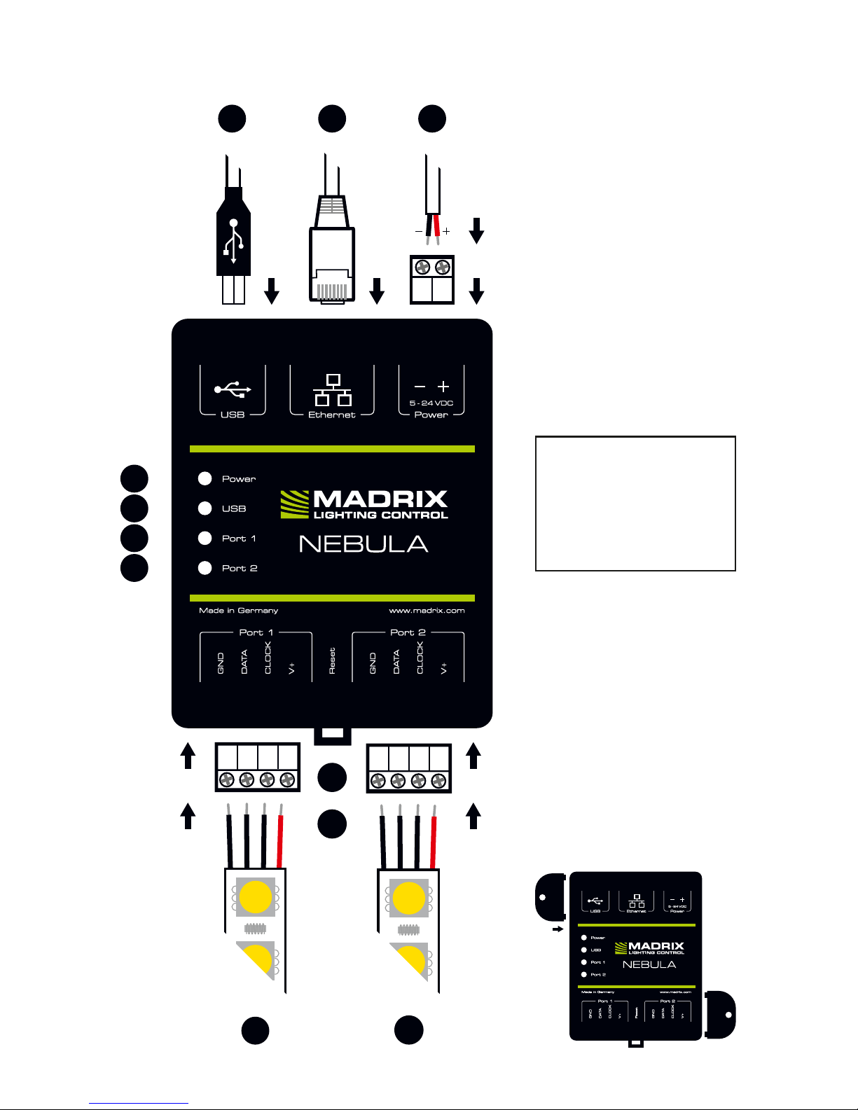
1) Power
2) RJ45 Ethernet port,
incl. 2 status LEDs
3) USB port
4) Status LED for Power
5) Status LED for USB
6) Status LED for Port 1
7) Status LED for Port 2
8) Port 1
9) Reset button
10) DIN-rail unlocking clip
11) Port 2
2x Mounting brackets:
GROUND
DATA
CLOCK
V+
GROUND
DATA
CLOCK
V+
11
10
9
8
7
6
5
4
3
2
1
Please note:
The package contents
do not include network
cables, power cables,
or LEDs.
Page 9
EN 8
English
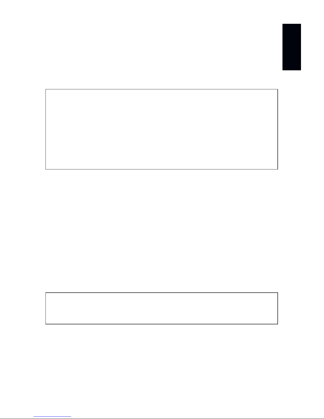
1) Connecting Your LEDs
See chapter ‘Connection Diagram Variations’ on page 9 for all possible variations.
Step 1) Completely switch off your supply of power before connecting your
LEDs to the device!
Step 2) Connect your LEDs to the provided 4-pin screw terminals:
Step 3) Plug the 4-pin screw terminals into the device. The screws must face
upwards.
Step 4) Supply your LEDs with power (per port or jointly) as per their manual.
Step 5) Continue with the chapter ‘2) Connecting To Power And Data’ below.
2) Connecting To Power And Data
See chapter ‘Connection Diagram Variations’ on page 9 for all possible variations.
Step 1) Be careful when handling the device and electrical power! Completely
switch off your supply of power before connecting to the device!
Step 2) Connect your power cables to the provided 2-pin screw terminal:
Step 3) Plug the 2-pin screw terminal into the device. The screws must face
upwards.
Step 4) Connect to USB or to Ethernet network for data as required.
Step 5) Do not switch on your supply of power until all required power cables
and LEDs are connected to MADRIX® NEBULA.
Step 6) Continue by selecting the required output protocol as described in
chapter ‘3) Configuration (Setting The Output Protocol)’ on page 14.
» The max. recommended wire length between NEBULA and LEDs or between
LEDs depends on the protocol, signal frequency, cables, and cable shielding.
» You may connect only to Port 1, only to Port 2, or to Port 1 and Port 2.
» Pay attention where to connect GROUND, DATA, CLOCK, and V+; as
indicated on the LEDs and the device as well as required by the diagram.
» You may connect 4-pin LEDs as well as 3-pin LEDs without CLOCK.
» Insert each individual wire consecutively and tighten the corresponding
screw with a suitable screw driver.
» Pay attention where to connect + and –; as indicated on the device.
» Insert each individual wire consecutively and tighten the corresponding
screw with a suitable screw driver.
Page 10
9 EN
Connection Diagram Variations
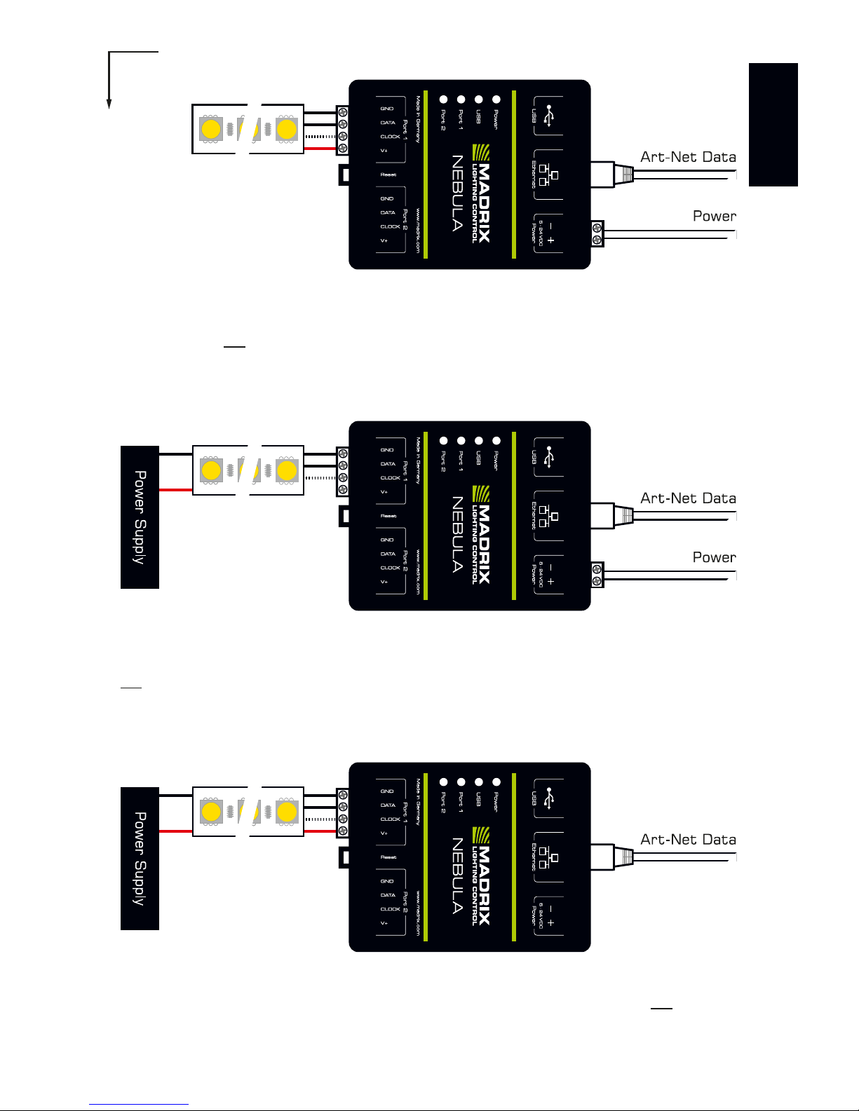
You can connect your LEDs, MADRIX® NEBULA, and data cables in different
ways. The following pages show the different variations as connection diagrams.
These schemes are to be seen independently of the direction, position, and
mounting method. Variation A1 to Variation D refer to the data connection over
Art-Net. Variation X1 to Variation Z refer to the data connection over USB.
Please see page 7 and page 8 for further information.
SUPPLY POWER TO NEBULA ONLY ONCE! DO NOT CONNECT V+
MULTIPLE TIMES BY CONNECTING IT VIA PORT 1/2 AND POWER.
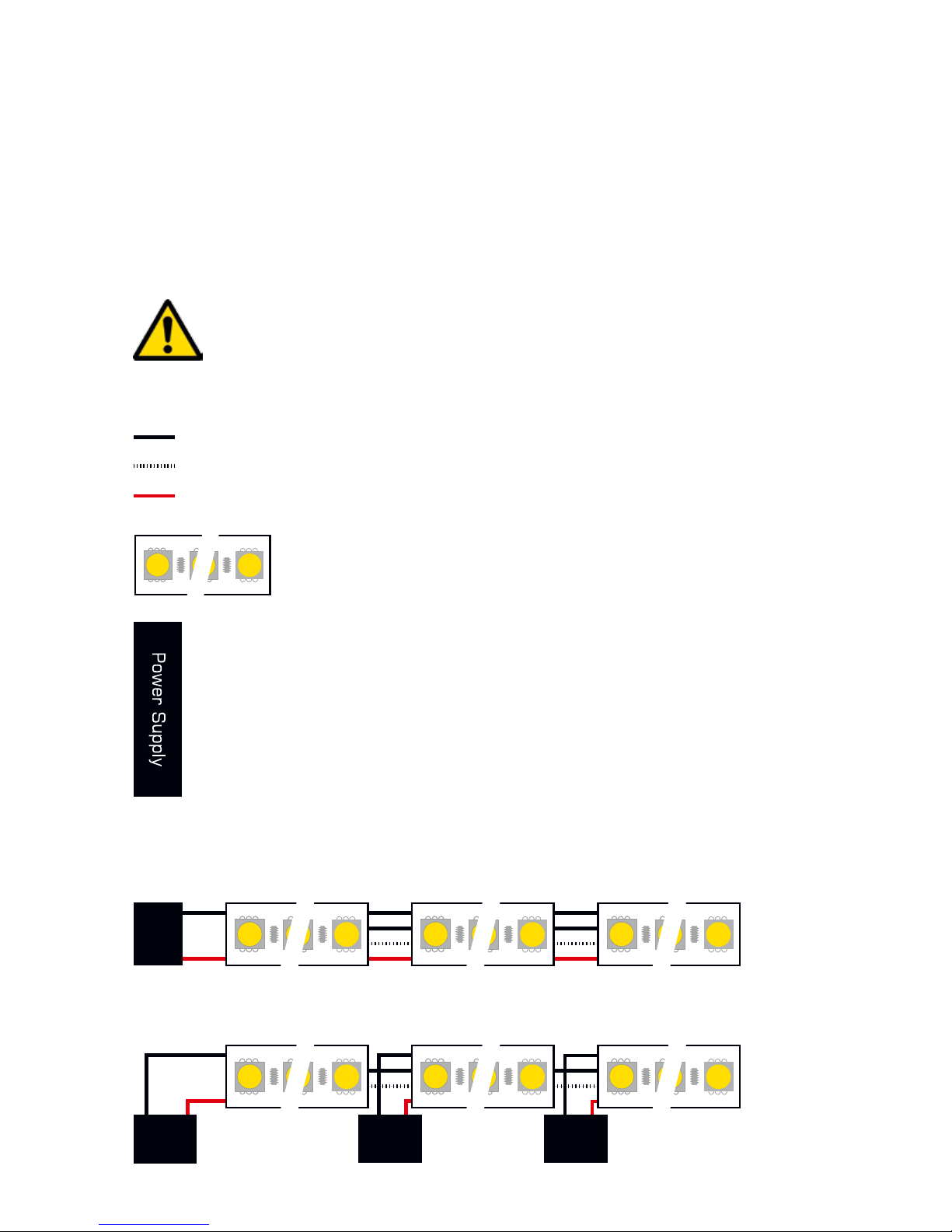
Legend
Connection required for GROUND / DATA.
Connection possible for CLOCK if needed.
Connection required for V+.
Represents single LEDs or multiple LED stripes / LED strips
/ LED tape up to the maximum possible amount per port.
Represents as many power supplies as needed for the
amount of your LEDs. May represent a joint power supply
for several LED tapes or may represent several, seperate
power supplies for several LED tapes and ports. Please
mind the correct supply of power for your LEDs and their
correct direction as per their user manual!
How To Connect Multiple LEDs
When your power supply provides power for multiple LED stripes, for example:
When your power supply only provides power for 1 LED stripe, for example:
Power
Supply
Connection
To NEBULA
GROUND
V+
Power
Supply
Connection
To NEBULA
Power
Supply
Power
Supply
GROUND
V+
Page 11
EN 10
English
Variation A1 – Port 1 or 2
Description: Power is supplied only once. It is supplied to NEBULA with 12 A max. and routed
through to the LEDs, which are connected only to Port 1 or only to Port 2 via GROUND, DATA,
possibly CLOCK, and V+ with 6 A max. load for the port.
Variation B1 – Port 1 or 2
Description: Power is supplied to NEBULA and supplied separately to the LEDs (as required). The
LEDs are connected only to Port 1 or only to Port 2 via GROUND, DATA, and possibly CLOCK, but
not via V+!
Variation C1 – Port 1 or 2
Description: Power is supplied only once. It is supplied to the LEDs (as required). The LEDs are
connected only to Port 1 or only to Port 2 via GROUND, DATA, possibly CLOCK, and V+. This
variation is suitable for LEDs that use > 9 V, due to the expected voltage drop over the length.
Alternative: Position the power supply between LEDs and NEBULA for LEDs with 5 V power supply.
Art-Net
Page 12
11 EN
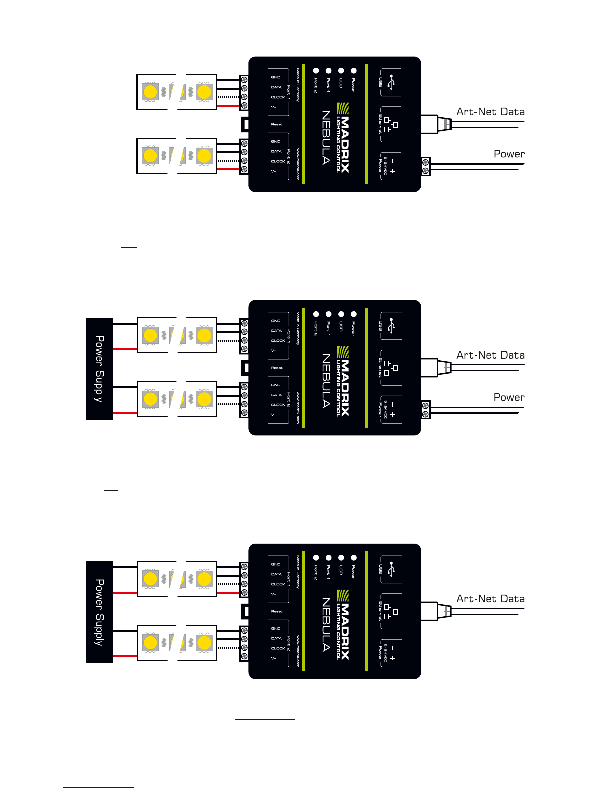
Variation A2
Description: Power is supplied only once. It is supplied to NEBULA with 12 A max. and routed
through to all LEDs, which are connected to Port 1 and to Port 2 via GROUND, DATA, possibly
CLOCK, and V+ with 6 A max. load for each port.
Variation C2
Description: Power is supplied to both LEDs (as required). LEDs are connected to both ports via
GROUND, DATA, possibly CLOCK, but only once via V+! This variation is suitable for LEDs that use
> 9 V, due to the expected voltage drop over the length.
Alternative: Position the power supply between LEDs and NEBULA for LEDs with 5 V power supply.
Variation B2
Description: Power is supplied to NEBULA and supplied separately to the LEDs (as
required). LEDs are connected to both ports via GROUND, DATA, and possibly CLOCK,
but not via V+!
Page 13
EN 12
English
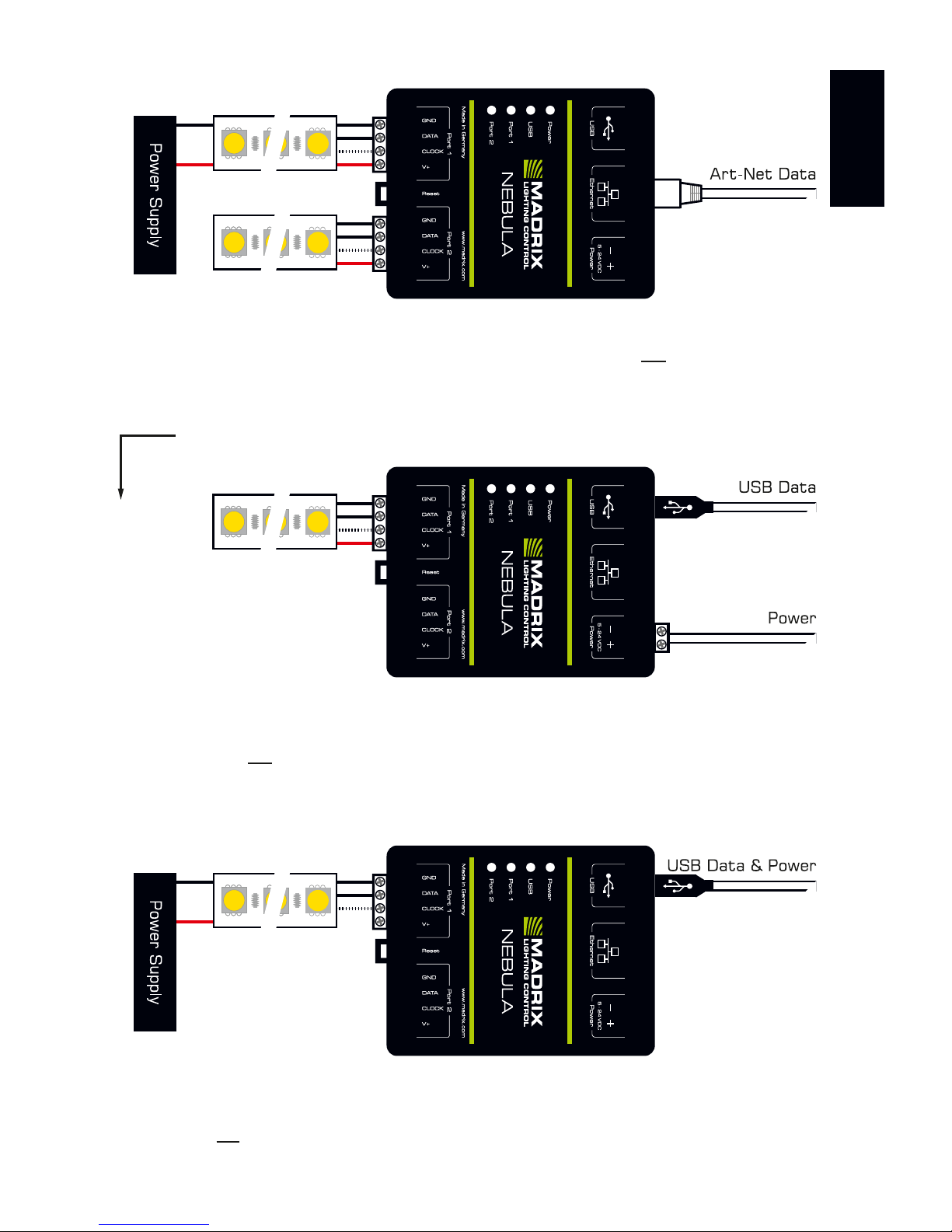
Variation D
Description: Power is supplied only once and it is only supplied to the first LEDs (as required)!
LEDs are connected to both ports via GROUND, DATA, possibly CLOCK, and V+ (6 A max.). This
variation is recommended for LEDs that use > 9 V, due to the expected voltage drop.
Alternative: Position the power supply between LEDs and NEBULA for LEDs with 5 V power supply.
Variation X1 – Port 1 or 2
Description: Power is supplied only once. It is supplied to NEBULA with 12 A max. and routed
through to the LEDs, which are connected only to Port 1 or only to Port 2 via GROUND, DATA,
possibly CLOCK, and V+ with 6 A max. load for the port.
Variation Y1 – Port 1 or 2
Description: Power is supplied to NEBULA over USB and supplied separately to the LEDs (as
required). The LEDs are connected only to Port 1 or only to Port 2 via GROUND, DATA, and possibly
CLOCK, but not via V+!
USB
Page 14
13 EN
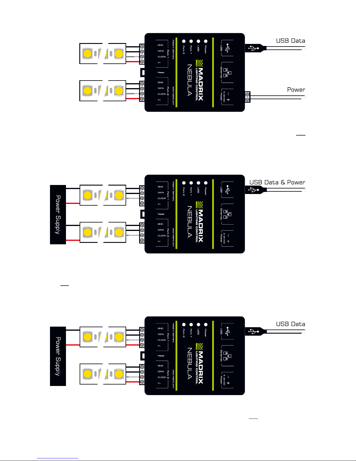
Variation Y2
Description: Power is supplied to NEBULA over USB and supplied separately to the LEDs
(as required). LEDs are connected to both ports via GROUND, DATA, and possibly CLOCK,
but not via V+!
Variation X2
Description: Power is supplied only once. It is supplied to NEBULA with 12 A max. and routed
through to all LEDs, which are connected to both ports via GROUND, DATA, possibly CLOCK, and
V+ with 6 A max. load for each port.
Variation Z
Description: Power is supplied only once and it is only supplied to the first LEDs (as required)!
LEDs are connected to both ports via GROUND, DATA, possibly CLOCK, and V+ (6 A max.).
This variation is recommended for LEDs that use > 9 V, due to the expected voltage drop.
Alternative: Position the power supply between LEDs and NEBULA for LEDs with 5 V power supply.
Page 15

EN 14
English
Web Configuration Through A Web Browser
Step 1) Connect MADRIX® NEBULA and your computer to the same network.
Step 2) Assign correct network settings in the Windows operating system.
(Recommended: IP address 10.0.0.1 / Subnet mask 255.0.0.0)
Step 3) Open your web browser and enter the IP address of MADRIX® NEBULA.
(You can find the default IP address on the side of the NEBULA device.)
Step 4) The built-in web configuration tool will be launched. Go to
‘Output Settings’ à ‘Output Protocol’ and choose the LEDs your are
using for ‘Port 1’ and ‘Port 2’. Apply changes with ‘Set’.
Step 5) Change any other settings as required. Apply changes with ‘Set’.
MADRIX Device Configuration In MADRIX
®
Step 1) Connect MADRIX® NEBULA to your computer via USB or via Ethernet.
Step 2a) For the USB connection, Microsoft® Windows® will install the
interface drivers automatically. When ready, the status LED for
USB will fade between red and green; as described on page 15. Start
the MADRIX® Software and enable USB drivers. Go to ‘Preferences’
à ‘Options…’ à tab ‘Devices USB’. Activate ‘MADRIX NEBULA’ and
click ‘OK’. (The driver is activated by default.)
Step 2b) For the Ethernet connection, enable network drivers in MADRIX®.
Go to ‘Preferences’ à ‘Options…’ à tab ‘Devices Network’.
Activate ‘Enable LUNA / NEBULA / PLEXUS / STELLA’ and click ‘OK’.
(The driver is activated by default.)
Step 3) In MADRIX®, go to ‘Tools...’ à ‘MADRIX Device Configuration...’. A
new window will open. Click on the search button (loupe
icon) and it will search for connected devices. Select your device in
the list and click on the configuration button (gear wheel icon).
Step 4) Go to ‘Port Output Settings’ and choose the LEDs your are using for
‘Port 1’ and ‘Port 2’. Apply changes with ‘Set’.
Step 5) Change any other settings as required. Apply changes with ‘Set’.
3) Configuration (Setting The Output Protocol)
You can access and change specific device settings, including the SPI protocol,
the IP address, and the number of channels sent per universe, in different ways.
Please note: In order to put MADRIX® NEBULA fully into operation, please
set the correct output protocol according to the LEDs you have connected.
Page 16
15 EN
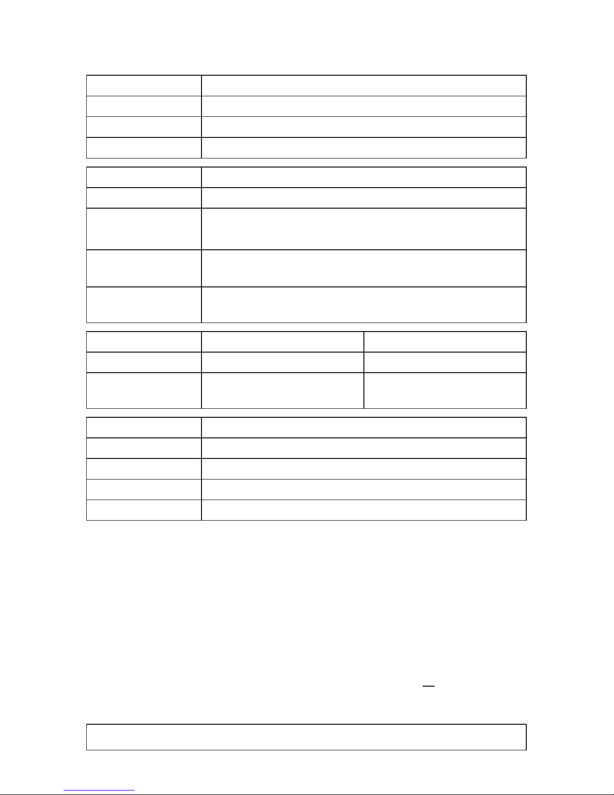
Description Of Status LED Codes
STATUS STATUS LED POWER
Powered off
Power not connected. The device has no power.
Permanently green
Connected to power. The power is on.
Blinking green
Bootloader activated. Reset the device (see below).
STATUS STATUS LED USB
Powered off
USB not connected.
Red +
blinking green
Communicating over USB.
Sending or receiving data over USB. The USB port works.
Fading between
red + green
Connected to USB; Drivers installed correctly.
No data is sent over USB.
Orange
Connected to USB; No drivers installed.
Reinstall software and drivers or try a different USB port.
STATUS STATUS LED PORT 1 STATUS LED PORT 2
Powered off
No data is sent. No data is sent.
Blinking green
Sending data to Port 1.
The output port works.
Sending data to Port 2.
The output port works.
STATUS STATUS LED ETHERNET
Green off 10 MBit/s connected.
Green on 100 MBit/s connected.
Orange on Network connected.
Orange blinking
Sending or receiving data. The Ethernet port works.
Reset To Factory Default Settings
In rare cases, you might need to do a reset to factory default settings:
Step 1) Disconnect all connections from the device (power, data, LEDs).
Step 2) Use a suitable tool to press the reset button (between Port 1 and 2).
Step 3) Continue to press the reset button and supply power again over
‘Power’ or USB.
Step 4) Continue to press the reset button and wait until all status LEDs
of the device flash repeatedly or wait 10 seconds.
Please note: Simply repeat these steps should the process fail.
Page 17
EN 16
English
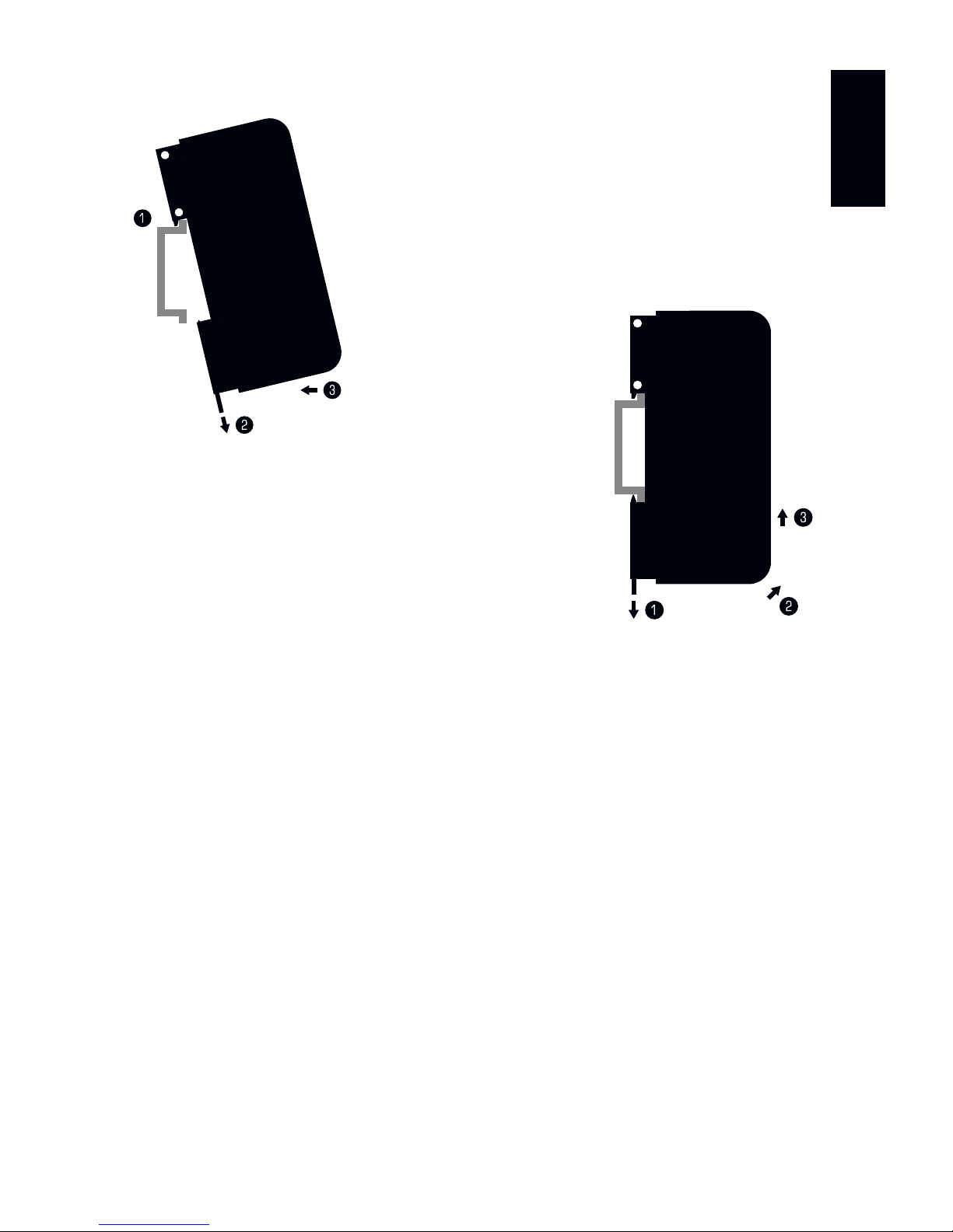
How To Install On DIN-Rails
Mounting (Pictured Left)
Step 1) Hook the device in an angle onto the upper
edge of the rail.
Step 2) Pull the unlocking clip.
Step 3) Press the lower part of the device against
the rail and let the clip snap into position.
Unmounting (Pictured Right)
Step 1) Pull the unlocking clip.
Step 2) Lift the lower part of the device from the
rail in an angle.
Step 3) Lift the device from the rail.
Using The MADRIX® Software And USB
You can connect MADRIX® NEBULA directly over USB to the computer that
runs the MADRIX® Software. Data is distributed to MADRIX® NEBULA via USB
cabling and sent to the output ports (Port 1 and Port 2):
Step 1) Put MADRIX® NEBULA into operation by connecting the LEDs,
supplying power, and setting the output protocol; as described above.
Step 2) Connect MADRIX® NEBULA to a free USB 2.0 port of your computer
using the provided USB cable.
Step 3) Enable USB drivers in MADRIX®. Go to ‘Preferences...’ à ‘Options…’
à tab ‘Devices USB’. Activate ‘MADRIX NEBULA’ and click ‘OK’.
Step 4) Configure the output. Go to ‘Preferences...’ à ‘Device Manager...’
à tab ‘DMX Devices’. Activate ‘Enable’ for each required output port.
Step 5) Configure your virtual LED matrix using ‘Preferences...’
à ‘Matrix Generator...’ or à ‘Patch Editor...’.
For more information, please read the MADRIX® user manual.
Page 18

17 EN
Using The MADRIX® Software And Art-Net
You can connect MADRIX® NEBULA over Ethernet network to the network card
of the computer that runs the MADRIX® Software. Data is distributed to the
device over network cabling and sent to the output ports (Port 1 and Port 2).
Follow these quick steps to configure Art-Net in the MADRIX® Software:
Step 1) Put MADRIX® NEBULA into operation by connecting the LEDs,
supplying power, and setting the output protocol; as described above.
Step 2) Connect NEBULA to your computer using Ethernet network cabling.
Step 3) Assign correct network settings for your PC in the Windows operating
system. (Recommended default settings:
IP address 10.0.0.1 / Subnet mask 255.0.0.0)
Step 4) Start the MADRIX® Software and go to ‘Preferences...’ à ‘Device
Manager...’ à tab ‘Art-Net’ and activate ‘Enable’. Click on the
search button (loupe icon) and the device appears in the list.
Step 5) Go to ‘Preferences...’ à ‘Device Manager...’ à tab ‘DMX Devices’
to configure the output. Activate ‘Enable’ for each required output
port in the section ‘Settings’.
Step 6) Configure your virtual LED matrix using ‘Preferences...’
à ‘Matrix Generator...’ or à ‘Patch Editor...’.
For more information, please read the MADRIX® user manual.
How To Update The Firmware
It is highly recommended to update the firmware of MADRIX® NEBULA should a
new firmware version become available. You can do so in different ways. Follow
these quick steps to update the firmware in the MADRIX® Software over USB:
Step 1) Connect MADRIX® NEBULA to your computer over USB.
Step 2) Start the MADRIX® Software.
Step 3) In the MADRIX® Software, go to ‘Tools...’ à ‘MADRIX Device
Configuration...’. A new window will open. Click on the search button
(loupe icon) and the software will search for connected devices.
Select your device in the list, click on the ‘Firmware’ button, and
follow any instructions.
For more information, please read the MADRIX® user manual.
Page 19
EN 18
English
Updates And Further Information
Digital documentation files are automatically installed with MADRIX®. More
information about the software and how to connect MADRIX® NEBULA is
provided in the MADRIX® Help And Manual. You can access this user manual
by pressing ‘F1’ on your keyboard while using the MADRIX® Software, by
navigating to the menu ‘Help’ à ‘User Manual…’, or online at help.madrix.com
The latest quick start guide and MADRIX® Software, including drivers, firmware
updates, and documentation, are available from www.madrix.com
Support
In case of further questions concerning handling of MADRIX® NEBULA or
technical problems, please read the MADRIX® Help And Manual first, contact
your dealer, or have a look at the website www.madrix.com
You can also directly contact [email protected]
CE And RoHS Declaration Of Conformity
The device complies with the requirements set forth in
the council Directive of the law of the Member States
relating to electromagnetic compatibility (2014/30/EU), the Low Voltage
Directive (2014/35/EU), and the Directive on the restriction of the use of
certain hazardous substances in electrical and electronic equipment (2011/65/
EU) (RoHS). Compliance with these has been evaluated in acc. with the following
standards: DIN EN 55011 (2009) + A1 (2010), DIN EN 55015 (2013), DIN
EN 55024 (2010), DIN EN 61000-4-2 (2009), DIN EN 61000-4-3 (2006) +
A1 (2008), DIN EN 61000-4-4 (2013), DIN EN 61000-4-6 (2014).
FCC Declaration Of Conformity
The device has passed the following tests of compliance:
FCC (2003) - Title 47, Part 15, class A, Radio frequency devices.
This device complies with part 15 of the FCC Rules. Operation is subject
to the following two conditions: (1) This device may not cause harmful
interference, and (2) this device must accept any interference received,
including interference that may cause undesired operation.
RoHS
compliant
Page 20

19 EN
Frequently Asked Questions (FAQs)
What do the blinking LEDs on the device mean?
Please read the chapter ‘Description Of Status LED Codes’ on page 15.
How can I change the IP address?
You can use the built-in web configuration tool as described on page 14.
The current IP address cannot be reached. What can I do?
You could perform a reset to factory default settings as described on page 15.
Does the device support RDM?
No. RDM is not supported by MADRIX® NEBULA at this time.
Is it possible to use more than one MADRIX® NEBULA?
Yes. Art-Net is recommended for large projects by connecting multiple devices
to a switch (1 GBit/s) via suitable components to create a network.
Where do I activate the Sync Mode?
You can activate it in the MADRIX® Software under ‘Preferences...’ à
‘Device Manager...’ à tab ‘Art-Net’.
Where can I find the latest firmware update?
The latest MADRIX® Software also includes the latest firmware (see p. 18).
Can I use other controllers apart from MADRIX® to control LEDs?
Yes. When using MADRIX® NEBULA as a standard Art-Net node, you can use
it in combination with other software applications, consoles, and controllers.
Do I need a MADRIX® NEBULA and a MADRIX® KEY?
If you want to use the MADRIX® Software, yes. The MADRIX® Software license
is necessary and sold separately.
Can I repair MADRIX® NEBULA myself?
No. Do not attempt any repairs. Any attempt will void your warranty (see p. 3)!
What can I do if my unit does not work anymore?
Please contact your dealer or supplier if the device seems to be defective.
Page 21

Deutsch
DE 1
MADRIX® NEBULA –
Kurzanleitung & Technisches Handbuch
3. Edition – September 2017
Vielen Dank, dass Sie sich für das MADRIX
®
NEBULA entschieden haben!
Bitte lesen Sie sich diese Kurzanleitung aufmerksam und sorgfältig vor der
Erstbenutzung durch. Vergewissern Sie sich, dass Sie alle Informationen
verstanden haben.
Diese Kurzanleitung wurde in englischer und deutscher Sprache verfasst.
(This MADRIX® NEBULA Quick Start Guide is written in English and German.)
Entwickelt und hergestellt in Deutschland.
Impressum
inoage GmbH
Wiener Straße 56
01219 Dresden
Deutschland
Geschäftsführer: Christian Hertel, Sebastian Pinzer, Sebastian Wissmann
Amtsgericht Dresden, HR B 29795
WEEE-Reg.-Nr. DE 26695213
USt-IdNr. DE276174128
Page 22

2 DE
Urheberrecht und Haftungsausschluss
© 2017 inoage GmbH. Alle Rechte vorbehalten. Änderungen und Irrtümer
vorbehalten. Reproduktion, Adaption oder Übersetzungen sind ohne vorherige,
schriftliche Erlaubnis nicht gestattet. Dieses Handbuch wurde mit größter
Sorgfalt verfasst. inoage GmbH gibt jedoch keine Gewähr hinsichtlich Richtigkeit,
Marktfähigkeit oder Eigenschaften des Produkts. Es gibt keinen rechtlichen
oder anderen Weg, Anspruch gegenüber inoage GmbH zu erheben. inoage
GmbH schließt jede Haftung für Schäden, Nachteile sowie Folgeschäden aus,
die durch Umsatzausfall sowie durch die Benutzung des Produktes, durch den
Verlust der Betriebsfähigkeit des Produktes, durch unsachgemäße Benutzung,
Ereignisse, Umstände oder Handlungen, auf die inoage GmbH keinen Einfluss
hat, ganz gleich, ob es sich um direkte oder indirekte Schäden, Folgeschäden
oder spezielle Schäden handelt und ob diese vom Besitzer oder einer dritten
Person verursacht wurden.
Eingetragene Marken
Microsoft®, Windows® sind eingetragene Marken der Microsoft Corporation.
Art-Net™: Entwicklung und Copyright Artistic Licence Holdings Ltd. Alle anderen
genannten Produkte können eingetragene Marken der jeweiligen Firmen sein.
MADRIX® ist eine eingetragene Marke der inoage GmbH.
Lieferumfang
1x MADRIX® NEBULA
1x Set an Schraubklemmen (2x 4-polig und 1x 2-polig)
1x USB 2.0-Kabel
(zertifiziert)
2x Wandhalterungen zur Wandmontage
1x Kurzanleitung
Hinweis: Überprüfen Sie den Verpackungsinhalt und das Gerät nach dem
Auspacken. Kontaktieren Sie bitte Ihren Händler, sollte der Inhalt unvollständig
oder beschädigt sein. Verwenden Sie das Produkt nicht bei Beschädigung!
Page 23
Deutsch
DE 3
Sicherheitshinweise und Garantie
Der Käufer dieses Produktes erhält zwei Jahre Herstellergarantie auf das
Produkt hinsichtlich Konstruktions- und Designfehler, Materialfehler oder
fehlerhafte Montage soweit diese durch den Hersteller verursacht wurden
oder er diese zu verantworten hat. Die Garantie erlischt sobald das Gerät
geöffnet, verändert, modifiziert oder durch unsachgemäße Handhabung, durch
Überspannung oder durch anderweitige Ursachen beschädigt wurde.
Bitte beachten Sie die nachstehenden Hinweise, um falsche Handhabung,
gesundheitliche Schäden und Geräteschäden zu vermeiden:
Betreiben Sie das Gerät nur in trockener Umgebung (Gebrauch in
geschlossenen Räumen). Die Schutzklasse des Gerätes ist IP20.
Vermeiden Sie hohe Luftfeuchtigkeit und Kontakt mit Wasser
und jeglichen anderen Flüssigkeiten. Trennen Sie das Gerät bei längerer
Nichtbenutzung von der Spannungsversorgung.
Entfernen Sie keine Teile vom Gerät oder andere Bauteile und verbinden Sie
es niemals mit einem ungeerdeten Stromkreis. Schließen Sie das Gerät nicht
an eingeschaltete LEDs an. Verbinden Sie nur LEDs und Steuergeräte, welche
zunächst ausgeschaltet sind.
Es gibt keine vom Benutzer zu wartenden Teile innerhalb des Gerätes. Eventuelle
Reparaturarbeiten obliegen dem Hersteller. Wenden Sie sich bei Defekt bitte an
Ihren Händler. Nach Ablauf der Garantie können kostenpflichtige Reparaturen
beim Händler bzw. Hersteller angefragt werden.
Verbinden Sie nur Geräte, Kabel, Anschlüsse, o.Ä., die dem Typ des jeweiligen
Anschlusses am Gerät entsprechen. Verbinden und benutzen Sie keine Geräte
mit falschen Anschlüssen.
Das Gerät sollte vom Fachmann installiert werden. Es ist für den professionellen
Gebrauch vorgesehen und nicht für Kinder bestimmt.
DAS GERÄT ARBEITET MIT KLEINSPANNUNG (5 V – 24 V
GLEICHSTROM). NUTZEN SIE NUR DIESE SPANNUNG!
▴
!
Page 24

4 DE
Altgeräte und Entsorgung
Das Gerät, sein Zubehör sowie Verpackungsmaterial müssen
ordnungsgemäß entsorgt werden. Geben Sie nichts in den Hausmüll.
inoage GmbH ist beim bundesweiten Rücknahmesystem für Elek tronische Geräte (EAR) registriert (WEEE-Reg.-Nr. DE 26695213).
Benutzung
Das Gerät empfängt Steuerdaten über Netzwerk (Art-Net) oder über USB und
wandelt diese in unterstützte SPI-Datenprotokolle für LEDs / Chips um. Es wird
an verschiedene, steuerbare Leuchtprodukte / Steuergeräte angeschlossen.
Verwenden Sie das Gerät nur zu seinem vorgesehenen Zweck. Das Gerät kann
während der Benutzung und ohne Neustarten des PCs von USB oder Netzwerk
getrennt und daran angeschlossen werden (sog. Hot Swapping und Plug &
Play). Mehrere Geräte können zur selben Zeit betrieben werden.
Technische Daten
Stromversorgung:
(Siehe Seiten 7 – 13)
Stromaufnahme:
Datenausgabe:
Anschlüsse:
Netzwerk (Art-Net):
USB-Anschluss:
Gehäuse:
Abmaße:
Gewicht:
Temperaturbereich:
Relative Luftfeuchte:
Datenprotokolle:
(Stand September 2017 –
Neueste Informationen auf
www.madrix.com)
5 V – 24 V Gleichstrom, über A) 2-polige Schraubklemme
(max. 12 A), B) 5 V USB oder C) Port 1 oder 2; max. 6 A
Last je Anschluss bei gleichzeitiger Speisung d. LEDs
< 1,5 W im Normalbetrieb (max. 300 mA)
8x 512 Kanäle “SPI” (max. Ausgabe pro Anschluss:
680 RGB-LEDs / 512 RGBW-LEDs / 2048 1-Kanal-LEDs)
2x Anschlüsse (über 2x 4-polige Schraubklemmen)
RJ45, 10/100 MBit/s (mit 1 GBit/s kompatibel)
USB 2.0, Stecker vom Typ B
Nicht leitend, Schutzklasse IP20, Brennbarkeit nach
UL94 V-0, für 35-mm Hutschienen oder Wandmontage
92 mm x 70 mm x 45 mm (Länge x Breite x Höhe)
111 g | 130 g inkl. Schraubklemmen und Wandhalterung
-10 °C bis 70 °C (Betrieb) | -20 °C bis 85 °C (Lagerung)
5 % bis 80 %, nicht kondensierend (Betrieb / Lagerung)
APA101, APA102, APA104, APA106, GW6201, GW6205, LPD1882S, LPD6803,
LPD8806, MBI6120, P9883, SJ1221, SK6812, SK6822, SM16703, SM16716,
TLS3001, TLS3008, TM1804, TM1809, TM1812, TM1814, TM1829, UCS1903,
UCS512B3, WS2801, WS2803, WS2811, WS2811S, WS2812, WS2812B,
WS2813, WS2815, WS2818, WS2822S, WS2822S Addressing
Page 25
Deutsch
DE 5
IP-Adresse und andere wichtige Informationen
Sie finden folgende, wichtige Informationen auf der Seite des Gerätes:
• Seriennummer (“Serial”)
• Hardwareversion (“Model”)
• Vorkonfiguration und Standardeinstellung der IP-Adresse (“Default IP”)
(Seite 15 beschreibt das Zurücksetzen des Gerätes, falls benötigt.)
Nutzung von anderen Zuspielern über Art-Net
MADRIX® NEBULA ist ein standardisiertes Art-Net-Gerät. Deshalb kann das
Gerät mit sämtlichen Zuspielern, die Art-Net unterstützen, betrieben werden.
Nutzung der MADRIX®-Software
Für den Zugang zu allen Funktionen des Gerätes (inkl. der USB-Verbindung,
Art-Net und Synchronisationsmodus) wird die MADRIX®-Software empfohlen.
Min. Systemanforderungen für MADRIX® und
unterstützte Betriebssysteme
Die aktuellsten Informationen stehen zur Verfügung auf www.madrix.com
Die MADRIX®-Software setzt die folgenden Anforderungen mindestens voraus.
Die optimalen Systemspezifikation sind oftmals höher.
• Zweikern-Prozessor mit 2,0 GHz, Grafikkarte mit OpenGL 2.1
(NVIDIA wird empfohlen), 2 GB RAM, 1 GB freier Festplattenspeicherplatz,
Monitorauflösung von 1280 x 768, Netzwerkkarte, Soundkarte, USB 2.0
Die MADRIX®-Software unterstützt die folgenden Betriebssysteme:
• Microsoft® Windows® 7 | 8 | 8.1 | 10
System, Treiber und Updates
bitte aktuell halten.
Hinweis: Zur Ausgabe von Daten über das MADRIX® NEBULA wird eine Lizenz
für die MADRIX®-Software benötigt (separat erhältlich)!
Page 26
6 DE
Installation MADRIX®-Software und Treiber
Installieren Sie die MADRIX®-Software auf Ihrem betriebsbereiten Computer
mit Hilfe von CD, USB-Stick oder heruntergeladener Installationsdatei. Folgen
Sie den Anweisungen auf dem Bildschirm, wie im Folgenden beschrieben.
INSTALLIEREN SIE BITTE DIE SOFTWARE UND TREIBER
BEVOR SIE DAS GERÄT AN DEN PC ANSCHLIESSEN.
Klicken Sie im zweiten Schritt auf “Weiter >”, um die Installation zu starten.
Im dritten Schritt erscheint das “Lizenzabkommen”. Es umfasst die
Vereinbarungen zur Nutzung der Software. Bitte klicken Sie auf “Annehmen”,
um zuzustimmen und fortzufahren.
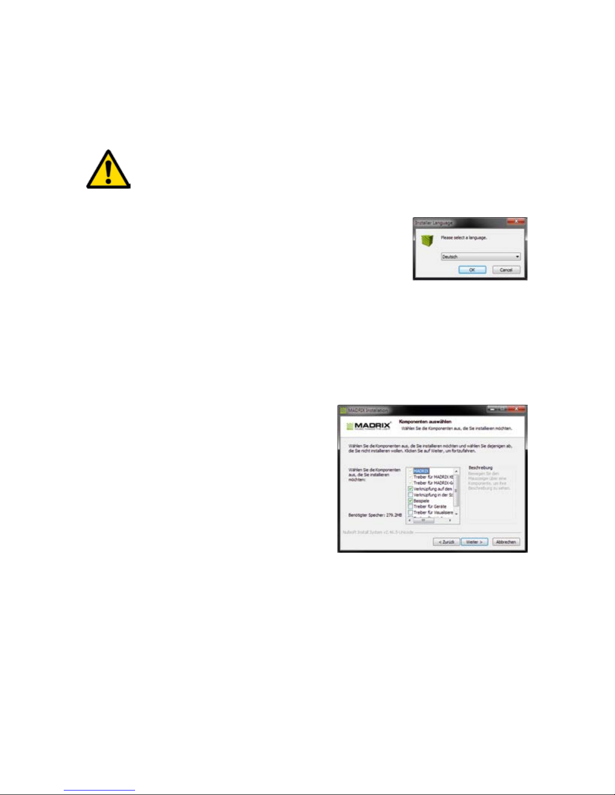
Wählen Sie im ersten Schritt Ihre bevorzugte Sprache
aus. Bestätigen Sie mit “OK”. Der Installationsvorgang
kann jeder Zeit mit “Cancel” (“Abbrechen”) beendet
werden.
Das vierte Fenster stellt die Komponenten
zur Auswahl. Eine Erklärung ist für jede
Komponente gegeben. Die Komponenten
“MADRIX”, “Treiber für MADRIX KEY”
und “Treiber für MADRIX-Geräte” müssen
ausgewählt sein (Häkchen gesetzt), da sie
für den Gebrauch des NEBULA nötig sind.
Bestätigen Sie mit “Weiter >”.
Im fünften Fenster “Zielverzeichnis auswählen” wird nach dem Installationsort
gefragt. Bitte wählen Sie einen Ort auf Ihrer Festplatte mit Hilfe von
“Durchsuchen...” aus und klicken Sie im Anschluss auf “Installieren”.
Die Installation kann einige Minuten Zeit in Anspruch nehmen.
Wenn im sechsten Schritt das Fenster “Die Installation ist vollständig” erscheint,
klicken Sie bitte auf “Weiter >”.
Im siebten Fenster klicken Sie bitte zum Abschluss auf “Fertig stellen”.
Page 27
Deutsch
DE 7
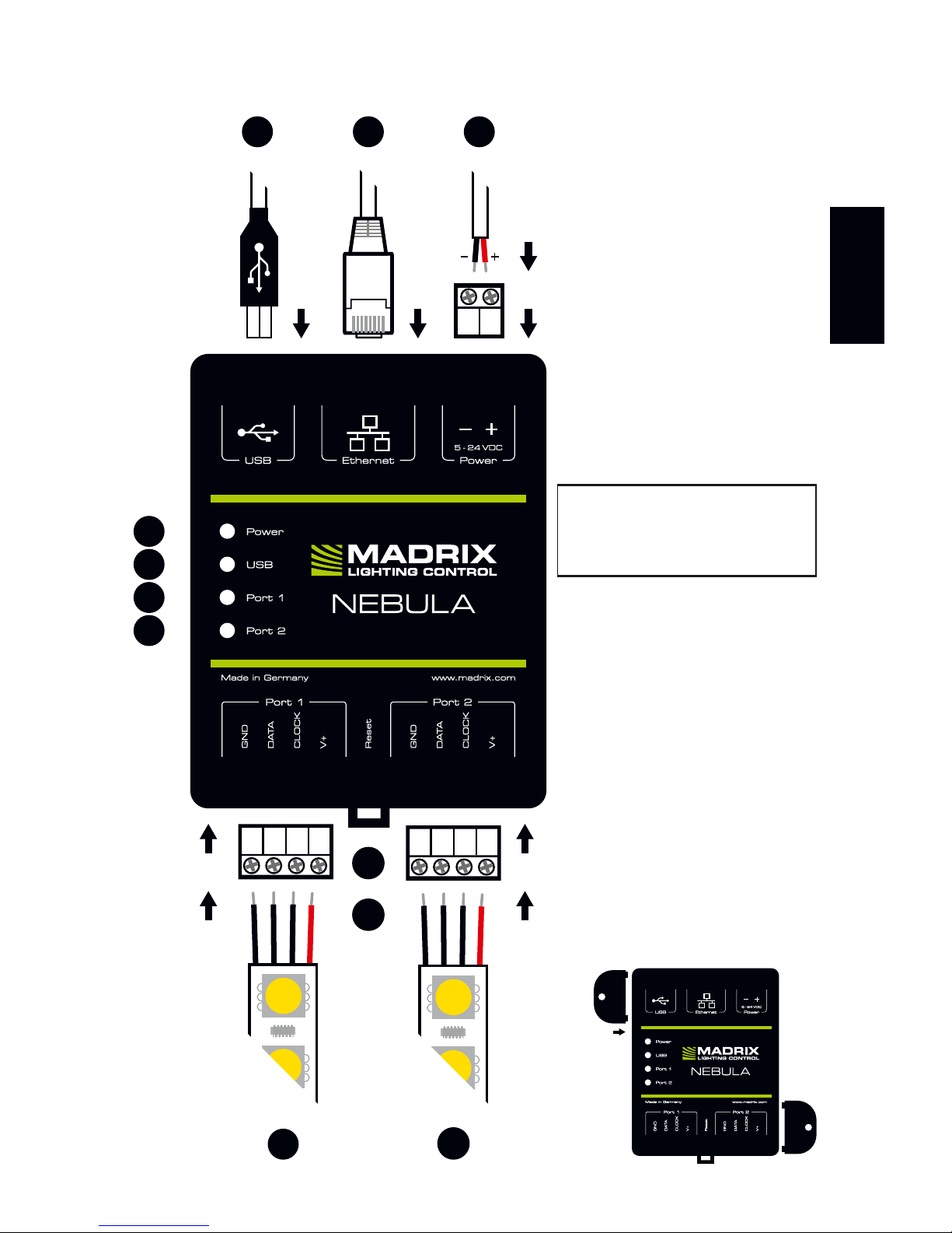
Anschlussmöglichkeiten
1) Spannungsversorgung
2) RJ45-Netzwerkanschluss,
inkl. 2 Status-LEDs
3) USB-Anschluss
4) Status-LED für Strom
5) Status-LED für USB
6) Status-LED für Anschluss 1
7) Status-LED für Anschluss 2
8) Anschluss 1 (Port 1)
9) “Reset”-Taste
10) Hutschienen-Entriegelung
11) Anschluss 2 (Port 2)
2x Wandhalterungen:
GROUND
DATA
CLOCK
V+
GROUND
DATA
CLOCK
V+
11
10
9
8
7
6
5
4
3
2
1
Hinweis: Netzwerkkabel,
Stromkabel oder LEDs sind
nicht im Paket enthalten.
Page 28
8 DE
1. Anschluss der LEDs
Alle möglichen Varianten finden Sie im Kapitel “Anschlussvarianten” ab Seite 9.
Schritt 1) Schalten Sie die Spannungsversorgung zunächst komplett aus!
Schritt 2) Anschluss der LEDs an die mitgelieferten 4-poligen Schraubklemmen:
Schritt 3) Die 4-poligen Schraubklemmen in das Gerät einstecken.
Die Schrauben der Klemme müssen dabei nach oben zeigen.
Schritt 4) Die LEDs pro Anschluss getrennt oder zusammen mit Spannung
versorgen, wie in deren Handbuch beschrieben.
Schritt 5) Weiter m. Kapitel “2. Anschluss Spannungsversorgung und Daten”.
2. Anschluss Spannungsversorgung und Daten
Alle möglichen Varianten finden Sie im Kapitel “Anschlussvarianten” ab Seite 9.
Schritt 1) Vorsicht beim Umgang mit Spannung! Schalten Sie die Spannungs-
versorgung zunächst komplett aus!
Schritt 2) Anschluss des Stromkabels an die 2-polige Schraubklemme:
Schritt 3) Die 2-polige Schraubklemme in das Gerät einstecken. Die Schrauben
der Klemme müssen dabei nach oben zeigen.
Schritt 4) Datenverbindung wie benötigt über USB oder Netzwerk herstellen.
Schritt 5) Die Spannungsversorgung erst herstellen, wenn alle Stromkabel
und LEDs an das MADRIX® NEBULA angeschlossen wurden.
Schritt 6) Bitte das richtige Ausgabeprotokoll einstellen, wie in Kapitel “3.
Konfiguration (Auswahl des Protokolls)“ auf Seite 14 beschrieben.
» Die max. empfohlene Länge zw. Gerät und LEDs sowie zw. LEDs hängt insb.
von Protokoll, Signalfrequenz, verwendetem Kabel und Kabelschirmung ab.
» Es kann Anschluss 1 oder 2 bzw. Anschluss 1 und 2 genutzt werden.
» GROUND (MASSE), DATA (DATEN), CLOCK (TAKT) und V+ müssen, wie
auf LEDs, dem Gerät und laut Diagramm dargestellt, verbunden werden.
» Es können auch 3-polige LEDs ohne CLOCK (TAKT) angeschlossen werden.
» Bitte jeden Draht einzeln und nacheinander verbinden und die entsprech ende Schraube mit einem passenden Schraubendreher festziehen.
» + und – müssen, wie auf dem Gerät dargestellt, verbunden werden.
» Bitte jeden Draht einzeln und nacheinander verbinden und die entsprech ende Schraube mit einem passenden Schraubendreher festziehen.
Page 29
Deutsch
DE 9
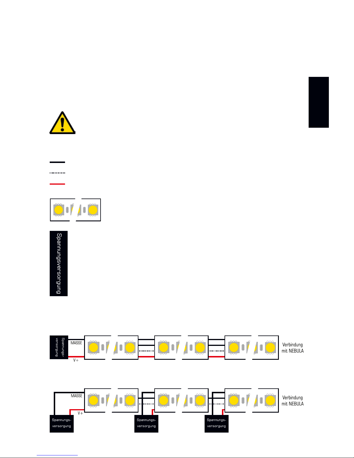
Ihre LEDs, MADRIX
®
NEBULA und die Datenkabel können auf verschiedene
Arten verbunden werden. Auf den folgenden Seiten sind die verschiedenen
Varianten als Verbindungsdiagramme dargestellt. Diese sind unabhängig von der
Ausrichtung, Platzierung oder Art der Montage. Varianten A1 bis D beziehen
sich auf die Datenverbindung über Art-Net. Varianten X1 bis Z beziehen sich auf
die Verbindung über USB. Weitere Informationen finden Sie auf Seite 7 und 8.
STELLEN SIE DIE SPANNUNGSVERSORGUNG FÜR NEBULA NUR
AUF EINEM WEG HER! SPEISEN SIE V+ NICHT MEHRFACH EIN.
Legende
Verbindung erforderlich für MASSE / DATEN.
Verbindung bei Bedarf möglich für TAKT.
Verbindung erforderlich für V+.
Repräsentiert einzelne oder mehrere LED-Ketten, bis zur
maximalen Anzahl an LEDs je Anschluss.
Repräsentiert die Anzahl an Spannungsversorgungen,
welche die verwendeten LEDs benötigen. Dabei kann eine
einzelne Versorgung für mehrere LED-Ketten, aber auch
mehrere Versorgungen je LEDs und Anschluss gemeint sein.
Bitte achten Sie auf die richtige Spannungsversorgung
sowie Richtung Ihrer LEDs laut deren Handbuch!
Verbinden von mehreren LED-Ketten
Wenn die Spannungsversorgung z.B. mehrere LED-Ketten versorgen kann:
Wenn die Spannungsversorgung z.B. nur eine LED-Kette versorgen kann:
Anschlussvarianten
Page 30
10 DE
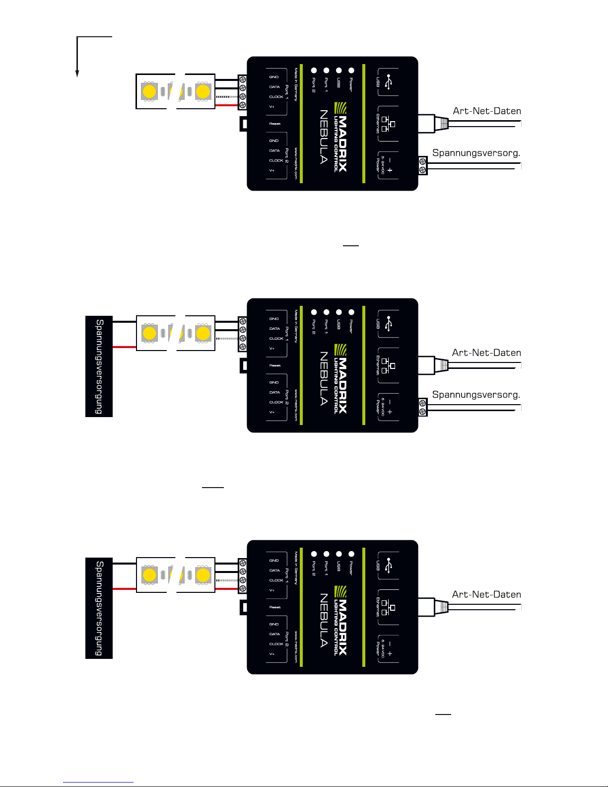
Variante A1 – Port 1 od. 2
Beschreibung: Die Spannungsversorgung wird einmal bereitgestellt und an NEBULA mit max.
12 A angeschlossen. Sie versorgt auch gleichzeitig die LEDs. Diese sind entweder an Anschluss 1
od. 2 angeschlossen über MASSE, DATEN, TAKT bei Bedarf und V+ mit max. 6 A Last am Anschluss.
Variante B1 – Port 1 od. 2
Beschreibung: Die Spannungsversorgung wird separat für NEBULA und die LEDs (wie benötigt)
bereitgestellt. Die LEDs sind entweder an Anschluss 1 oder 2 angeschlossen über MASSE, DATEN
und TAKT bei Bedarf, aber nicht über V+!
Variante C1 – Port 1 od. 2
Beschreibung: Die Spannungsversorgung wird einmal bereitgestellt und an die LEDs (wie benötigt)
angeschlossen. Die LEDs sind mit NEBULA über MASSE, DATEN, TAKT bei Bedarf und V+ verbunden.
Durch erwartbaren Spannungsabfall über die Länge der LED-Kette hinweg für LEDs mit > 9 V geeignet.
Alternative: Positionieren Sie die Spannungsversorgung zw. LEDs und NEBULA für LEDs mit 5 V.
Art-Net
Page 31
Deutsch
DE 11
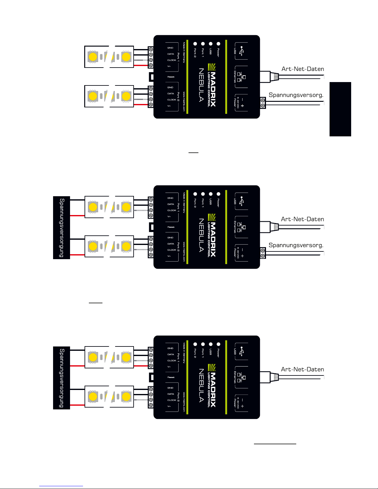
Variante A2
Beschreibung: Die Spannungsversorgung wird einmal bereitgestellt und an NEBULA mit max.
12 A angeschlossen. Sie versorgt auch gleichzeitig die LEDs. Diese sind an beiden Anschlüssen
verbunden über MASSE, DATEN, TAKT bei Bedarf und V+ mit max. 6 A Last je Anschluss.
Variante C2
Beschreibung: Die Spannungsvers. wird für alle LEDs (wie benötigt) bereitgestellt. LEDs sind an
beiden Anschlüssen verbunden über MASSE, DATEN und TAKT bei Bedarf, aber nur einmal über V+!
Durch erwartbaren Spannungsabfall über die Länge der LED-Kette hinweg für LEDs mit > 9 V geeignet.
Alternative: Positionieren Sie die Spannungsversorgung zw. LEDs und NEBULA für LEDs mit 5 V.
Variante B2
Beschreibung: Die Spannungsversorgung wird separat für NEBULA und die LEDs (wie benötigt)
bereitgestellt. LEDs sind an beiden Anschlüssen verbunden über MASSE, DATEN und TAKT bei
Bedarf, aber nicht über V+!
Page 32
12 DE
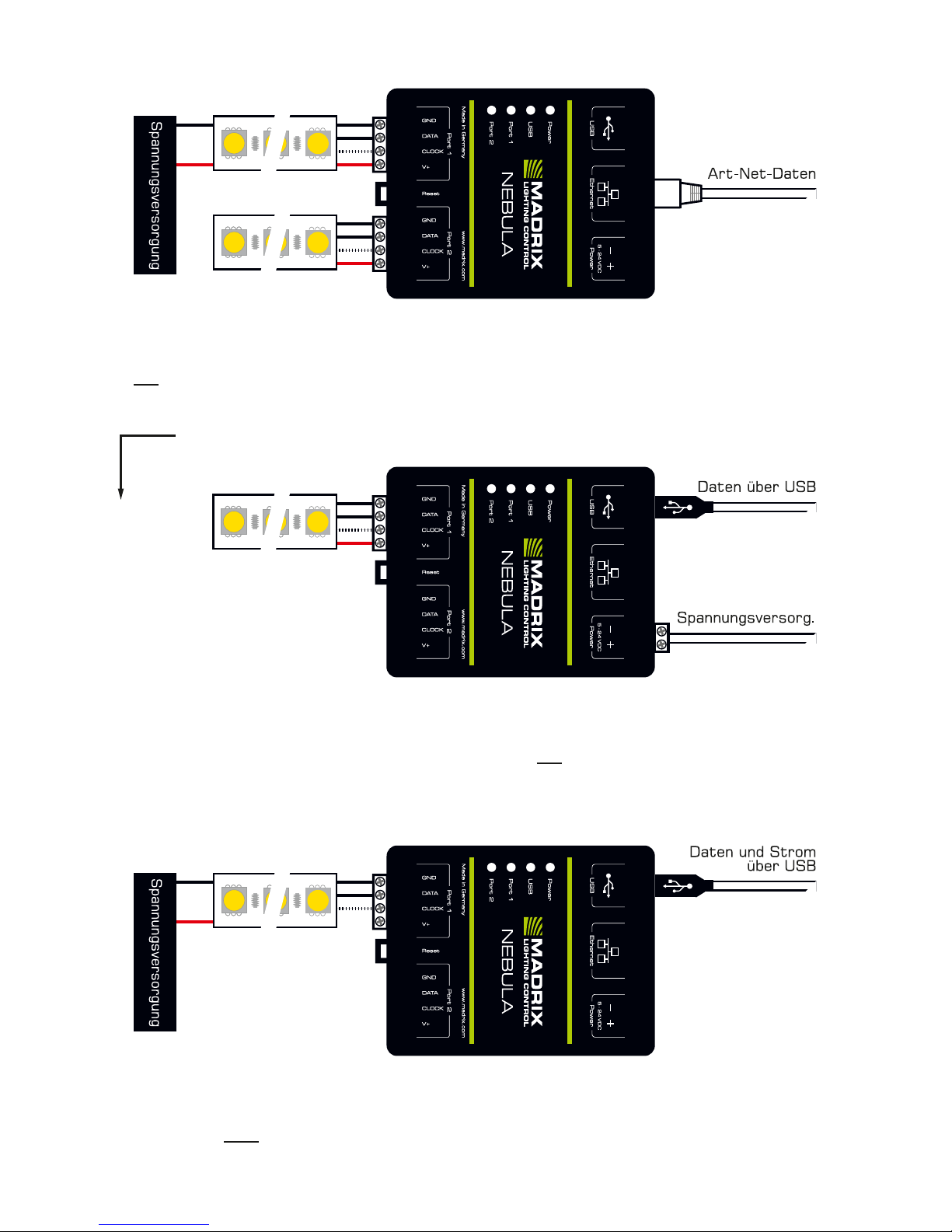
Variante Y1 – Port 1 od. 2
Variante X1 – Port 1 od. 2
Beschreibung: Die Spannungsversorgung wird einmal bereitgestellt und an NEBULA mit max.
12 A angeschlossen. Sie versorgt auch gleichzeitig die LEDs. Diese sind entweder an Anschluss 1
od. 2 angeschlossen über MASSE, DATEN, TAKT bei Bedarf und V+ mit max. 6 A Last am Anschluss.
Beschreibung: Die Spannungsversorgung wird separat für NEBULA (über USB) und die LEDs (wie
benötigt) bereitgestellt. Die LEDs sind mit NEBULA verbunden über MASSE, DATEN und TAKT bei
Bedarf, aber nicht über V+!
Variante D
Beschreibung: Die Spannungsvers. wird einmal bereitgestellt und nur an die ersten LEDs (wie
benötigt) angeschlossen! LEDs sind an beiden Anschlüssen über MASSE, DATEN, TAKT bei Bedarf
und V+ (max. 6 A) verbunden. Durch d. erw. Spannungsabfall ist d. Var. f. LEDs mit > 9 V geeignet.
Alternative: Positionieren Sie die Spannungsversorgung zw. LEDs und NEBULA für LEDs mit 5 V.
USB
Page 33
Deutsch
DE 13
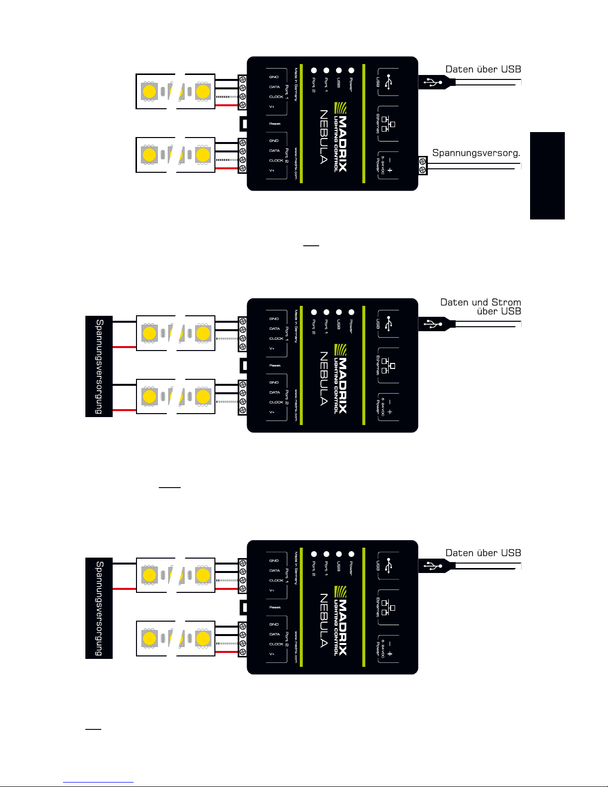
Variante Z
Beschreibung: Die Spannungsvers. wird einmal bereitgestellt und nur an die ersten LEDs (wie
benötigt) angeschlossen! LEDs sind an beiden Anschlüssen über MASSE, DATEN, TAKT bei Bedarf
und V+ (max. 6 A) verbunden. Durch d. erw. Spannungsabfall ist d. Var. f. LEDs mit > 9 V geeignet.
Alternative: Positionieren Sie die Spannungsversorgung zw. LEDs und NEBULA für LEDs mit 5 V.
Variante Y2
Beschreibung: Die Spannungsversorgung wird separat für NEBULA (über USB) und die LEDs (wie
benötigt) bereitgestellt. LEDs sind an beiden Anschlüssen verbunden über MASSE, DATEN und TAKT
bei Bedarf, aber nicht über V+!
Variante X2
Beschreibung: Die Spannungsversorgung wird einmal bereitgestellt und an NEBULA mit max.
12 A angeschlossen. Sie versorgt auch gleichzeitig die LEDs. Diese sind an beiden Anschlüssen
verbunden über MASSE, DATEN, TAKT bei Bedarf und V+ mit max. 6 A Last je Anschluss.
Page 34

14 DE
Konfiguration über einen Webbrowser
Schritt 1) Verbinden Sie NEBULA und den PC mit demselben Netzwerk.
Schritt 2) Stellen Sie die richtigen Netzwerkeinstellungen im Betriebssystem
ein. (Empfohlen: IP-Adresse 10.0.0.1 / Subnetzmaske 255.0.0.0)
Schritt 3) Öffnen Sie einen Webbrowser und geben Sie die IP-Adresse des
NEBULA ein. (Diese finden Sie auf der NEBULA-Geräteseite.)
Schritt 4) Wählen Sie in der erscheinenden Web-Konfiguration die
verwendeten LEDs für “Port 1” und “Port 2“ unter “Output
Settings” à “Output Protocol”. Bestätigen Sie mit “Set”.
Schritt 5) Ändern Sie weitere Einstellungen je nach Bedarf.
MADRIX-Gerätekonfiguration in MADRIX
®
Schritt 1) Verbinden Sie NEBULA mit dem Computer über USB oder Netzwerk.
Schritt 2a) Für die USB-Verbindung installiert Microsoft® Windows® die
Treiber automatisch. Bei Erfolg blendet die “Status-LED USB”
zwischen rot und grün über (siehe Seite 15). Danach in der MADRIX® Software die Treiber unter “Systemeinstellungen” à “Optionen…”
à Reiter “USB-Geräte” à “MADRIX NEBULA” aktivieren. Mit
“OK” bestätigen. (Der Treiber ist standardmäßig aktiviert.)
Schritt 2b) Für die Netzwerkverbindung in MADRIX® unter ”System einstellungen” à “Optionen…” à Reiter “Netzwerkgeräte”
à ”LUNA / NEBULA / PLEXUS / STELLA einschalten” aktivieren
und mit “OK” bestätigen. (Der Treiber ist standardmäßig aktiviert.)
Schritt 3) In MADRIX® “Werkzeuge...” à “MADRIX-Gerätekonfiguration...”
aufrufen und nach angeschlossenen Geräten mit Hilfe des Lupen Symbols suchen. Das Gerät anschließend in der Liste auswählen
und das Zahnrad-Symbol für die Konfiguration anklicken.
Schritt 4) Die verwendeten LEDs für “Anschluss 1” sowie “Anschluss 2” unter
“Einstellungen der Ausgabe-Anschlüsse” einstellen. Bestätigen Sie
Änderungen mit “Festlegen”.
Schritt 5) Ändern Sie weitere Einstellungen je nach Bedarf.
3. Konfiguration (Auswahl des Protokolls)
Einstellungen, wie Ausgabeprotokoll, IP-Adresse und Anzahl an gesendeten
Kanälen je Universum, können auf mehreren Wegen eingestellt werden.
Hinweis: Um MADRIX® NEBULA vollständig in Betrieb zu nehmen, muss das
richtige Ausgabeprotokoll je nach verbundenen LEDs eingestellt werden.
Page 35
Deutsch
DE 15
Zurücksetzen auf Werkseinstellungen
Führen Sie folgende Schritte für ein Zurücksetzen auf Werkseinstellungen aus:
Schritt 1) Trennen Sie alle Anschlüsse vom Gerät (Spannung, Daten, LEDs).
Schritt 2) Drücken Sie die “Reset”-Taste (zwischen Port 1 und Port 2).
Schritt 3) Halten Sie weiterhin die “Reset”-Taste gedrückt und stellen Sie die
Spannungsversorgung über “Power” oder USB wieder her.
Schritt 4) Halten Sie die “Reset”-Taste gedrückt und warten Sie bis alle Status LEDs des Gerätes schnell blinken oder warten Sie 10 Sekunden.
Hinweis: Wiederholen Sie die Schritte, sollte der Vorgang fehlschlagen.
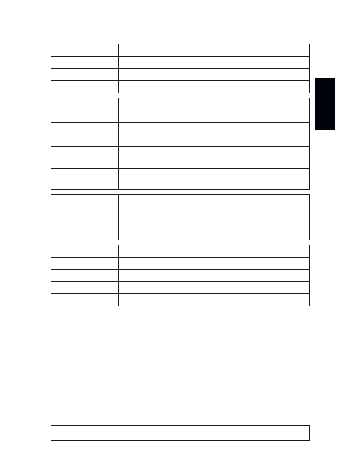
Anzeige der Status-LEDs
STATUS STATUS-LED POWER (SPANNUNGSVERSORGUNG)
Ausgeschaltet
Keine Spannungsversorgung. Das Gerät hat keinen Strom.
Permanent grün
Spannungsversorgung liegt an. Das Gerät hat Strom.
Grün blinkend
“Bootloader” aktiviert. Gerät zurücksetzen (siehe unten).
STATUS STATUS-LED USB
Ausgeschaltet
USB nicht angeschlossen.
Rot +
grün blinkend
Kommunikation über USB.
Daten werden gesendet. Der Anschluss arbeitet.
Überblenden zw.
rot + grün
Angeschlossen an USB; Treiber korrekt installiert.
Kein Datenverkehr über USB.
Orange
Angeschlossen an USB; Treiber nicht installiert.
Software/Treiber neu installieren; USB-Anschl. wechseln.
STATUS STATUS-LED PORT 1 STATUS-LED PORT 2
Ausgeschaltet
Kein Datenverkehr. Kein Datenverkehr.
Grün blinkend
Ausgabe von Daten.
Der Anschluss arbeitet.
Ausgabe von Daten.
Der Anschluss arbeitet.
STATUS STATUS-LED ETHERNET (NETZWERK)
Grün aus 10 MBit/s angeschlossen.
Grün an 100 MBit/s angeschlossen.
Orange an Netzwerk angeschlossen.
Orange blinkend
Datenverkehr über Netzwerk. Der Anschluss arbeitet.
Page 36
16 DE
Nutzung der Ausgabe über USB
MADRIX® NEBULA kann direkt über USB mit dem Computer verbunden werden,
auf dem die MADRIX®-Software genutzt wird. Daten werden über USB zum
Gerät und intern zu den beiden Anschlüssen gesendet (Port 1 und Port 2):
Schritt 1) Nehmen Sie MADRIX® NEBULA wie zuvor beschrieben in Betrieb.
Schritt 2) Verbinden Sie das Gerät mit Hilfe des mitgelieferten USB-Kabels
mit einem freien USB 2.0-Anschluss Ihres Computers.
Schritt 3) Starten Sie die MADRIX®-Software und aktivieren Sie die USB Treiber unter “Systemeinstellungen...” à “Optionen…” à Reiter
“USB-Geräte” à “MADRIX NEBULA” und bestätigen Sie mit “OK”.
Schritt 4) Konfigurieren Sie die Ausgabe unter “Systemeinstellungen...” à
“Geräteverwaltung...” à Reiter “DMX-Geräte” und aktivieren Sie
“Einschalten” für jeden benötigten Anschluss unter “Einstellungen”.
Schritt 5) Stellen Sie die virtuelle LED-Matrix unter “Systemeinstellungen...”
à “Matrixgenerator...” oder à “Beleuchtungsplaner...” ein.
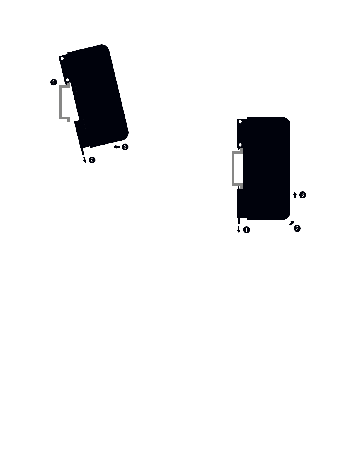
Montage auf Hutschienen
Montage (Links abgebildet)
Schritt 1) Hängen Sie das Gerät schräg auf die
obere Kante der Hutschiene ein.
Schritt 2) Lösen Sie die Entriegelung.
Schritt 3) Drücken Sie das Gerät auf die Schiene
und lassen Sie die Entriegelung einrasten.
Demontage (Rechts abgebildet)
Schritt 1) Lösen Sie die Entriegelung.
Schritt 2) Ziehen Sie den unteren Teil des Gerätes
schräg von der Schiene.
Schritt 3) Heben Sie das Gerät von der Hutschiene.
Page 37

Deutsch
DE 17
Nutzung von Art-Net
Das MADRIX® NEBULA kann über Netzwerk mit der Netzwerkkarte des
Computers verbunden werden, auf dem die MADRIX®-Software genutzt wird.
Daten werden über Netzwerk zum Gerät und danach intern zu den beiden
Anschlüssen gesendet (Port 1 und Port 2).
Folgen Sie dieser Kurzanleitung, um Art-Net in MADRIX® zu konfigurieren:
Schritt 1) Nehmen Sie MADRIX® NEBULA wie zuvor beschrieben in Betrieb.
Schritt 2) Verbinden Sie das Gerät mit Ihrem Computer über Netzwerk.
Schritt 3) Stellen Sie die richtigen Netzwerkeinstellungen für den PC
im Betriebssystem ein. (Empfohlene Standardeinstellungen für
Windows: IP-Adresse 10.0.0.1 / Subnetzmaske 255.0.0.0)
Schritt 4) Starten Sie die MADRIX®-Software und gehen Sie in das Menü
“Systemeinstellungen...” à “Geräteverwaltung...” à Reiter
“Art-Net” auf. Aktivieren Sie “Einschalten” und betätigen Sie das
Lupen-Symbol. Das Gerät erscheint in der Liste.
Schritt 5) Konfigurieren Sie die Ausgabe unter “Systemeinstellungen...” à
“Geräteverwaltung...” à Reiter “DMX-Geräte” und aktivieren Sie
“Einschalten” für jeden benötigten Anschluss unter “Einstellungen”.
Schritt 6) Stellen Sie die virtuelle LED-Matrix unter “Systemeinstellungen...”
à “Matrixgenerator...” oder à “Beleuchtungsplaner...” ein.
Aktualisieren der Firmware
Es wird empfohlen, immer die neueste Firmware für das MADRIX® NEBULA
zu verwenden. Das Aktualisieren kann auf mehreren Wegen erfolgen. Folgen
Sie dieser Kurzanleitung für das Aktualisieren der Firmware in der MADRIX®Software über USB:
Schritt 1) Verbinden Sie MADRIX® NEBULA mit Ihrem Computer über USB.
Schritt 2) Starten Sie die MADRIX®-Software.
Schritt 3) Öffnen Sie in der MADRIX®-Software das Menü “Werkzeuge...”
à “MADRIX-Gerätekonfiguration...”. Betätigen Sie das Lupen Symbol, um nach Geräten zu suchen. Wählen Sie das Gerät in der
Liste aus, klicken Sie auf “Firmware” und folgen Sie den weiteren
Anweisungen.
Page 38
18 DE
Aktualisierungen und weitere Informationen
Weitere Handbücher werden automatisch mit der MADRIX®-Software installiert
und somit digital bereitgestellt. Mehr Informationen finden sich im MADRIX®
Help And Manual, dem Handbuch zur Software. Es kann während des Arbeitens
mit MADRIX® durch die Taste “F1” auf der Tastatur, über das Menü “Hilfe” à
“Benutzerhandbuch…” oder online unter help.madrix.com aufgerufen werden.
Die neueste Version dieser Kurzanleitung sowie Software-Updates für die
MADRIX®-Software, inkl. Treiber, aktueller Firmware und aktueller Versionen
der Handbücher, sind im Internet erhältlich unter www.madrix.com
Hilfe und Support
Sollten weitere Fragen zur Handhabung oder technische Probleme auftauchen,
konsultieren Sie bitte die weiteren Benutzerhandbücher, kontaktieren Sie Ihren
Händler oder besuchen Sie die Internetseite www.madrix.com
Anfragen können auch direkt per Telefon oder per E-Mail erfolgen.
Konformitätserklärung für CE und RoHS
Das Gerät entspricht den Anforderungen der Richtlinie
der Mitgliedsstaaten über die elektromagnetische
Verträglichkeit (2014/30/EU), der Niederspannungsrichtlinie (LVD) (2014/35/
EU) und der Richtlinie zur Beschränkung der Verwendung bestimmter
gefährlicher Stoffe in Elektro- und Elektronikgeräten (2011/65/EU) (RoHS). Die
Einhaltung mit diesen Richtlinien wurde auf Grundlage der folgenden Standards
evaluiert: DIN EN 55011 (2009) + A1 (2010), DIN EN 55015 (2013), DIN EN
55024 (2010), DIN EN 61000-4-2 (2009), DIN EN 61000-4-3 (2006) + A1
(2008), DIN EN 61000-4-4 (2013), DIN EN 61000-4-6 (2014).
RoHS
compliant
Page 39

Deutsch
DE 19
Häufig Gestellte Fragen
Was bedeuten die leuchtenden LEDs auf dem Gerät?
Lesen Sie dazu bitte den Abschnitt “Anzeige der Status-LEDs” auf Seite 15.
Wie kann ich die IP-Adresse des Gerätes ändern?
Nutzen Sie die eingebaute Konfiguration über einen Webbrowser (siehe S. 14).
Das Gerät kann über die aktuelle IP-Adresse nicht erreicht werden.
Setzen Sie das Gerät auf die Werkseinstellungen zurück (siehe S. 15).
Unterstützt das Gerät RDM?
Nein. RDM wird von MADRIX® NEBULA aktuell nicht unterstützt.
Ist es möglich, mehr als ein MADRIX® NEBULA zu verwenden?
Ja. Art-Net wird für große Projekte mit mehreren Geräte empfohlen. Diese über
geeignete Komponenten mit einem Switch (1 GBit/s) als Netzwerk verbinden.
Wo kann ich den Modus zur Synchronisation einstellen?
Dieser kann in der MADRIX®-Software im Menü “Systemeinstellungen...” à
“Geräteverwaltung...” à Reiter “Art-Net” aktiviert werden.
Wo finde ich die aktuellste Firmware für mein Gerät?
Die aktuellste MADRIX®-Software enthält die aktuellste Firmware (siehe S. 18).
Kann ich andere Zuspieler an Stelle von MADRIX® benutzen?
Ja. Wenn Sie das Gerät als reinen Art-Net-Node nutzen möchten, ist die
Verwendung mit anderen Zuspielern möglich.
Brauche ich den MADRIX® KEY zusätzlich zum MADRIX® NEBULA?
Ja, wenn Sie MADRIX® nutzen möchten. Die Softwarelizenz ist separat erhätlich.
Kann ich das MADRIX® NEBULA selber reparieren?
Nein. Versuchen Sie keine Reparaturarbeiten. Jeglicher Versuch führt zum
Erlöschen der Garantie (siehe S. 3).
Was mache ich, wenn mein Gerät ausfällt?
Kontaktieren Sie bitte Ihren Händler bei Gerätedefekt.
Page 40
www.madrix.com
 Loading...