

Madrigal Imaging MP-9, MP-8 User Manual

Owner’s Manual
MP-8
MP-9
Projectors
Before operating the projector for the first time, read section 4.1 Warnings and Guidelines.
NOTICE
The projector generates and may radiate radio frequency energy. If not installed and used in accordance with this
manual, it may cause interference with radio communications.
The projector is tested to and complies with the limits for a Class A computing device pursuant to subpart J of
part 15 of FCC rules, which are designed to provide reasonable protection against interference in a commercial
environment. When the projector is operated in a residential area it may cause radio interference. In such a case
the user will be required, at his/her expense, to take measures required to correct the interference.
The projector is tested to and complies with the limits for a Class A digital apparatus pursuant to the Canadian
Department of Communications radio interference regulations. The regulations are designed to provide reasonable
protection against such interference from devices operated in a commercial environment.
Cet appareil à affichage numerique a été contrôlé. Il est conforme aux limites des reglements de la Classe A
d’appareils a affichage numérique établis par le Ministére des Communications du Canada en ce qui concerne
les interférences radio. Ces réglements ont été mis en place pour assurer une protection raisonnable contre les
interferences produits par des appareils utilisés dans un environnement commercial.
CAUTION
Only use attachments or accessories recommended by Madrigal Imaging. Use of others may result in the risk of
fire, shock or personal injury.
Typographical Conventions
Please note the following typographical conventions used throughout this manual.
❑ Warnings that relate to user safety are highlighted in BOLD print.
❑ First and second level subsection titles are located in the left margin of each page. Third level titles are located
within the body text and are in
bold italic print.
❑ The pointing hand symbol emphasizes important information within a subsection or paragraph.
❑ Key symbols ( , , , etc.), when located in the left margin, indicate initial keystrokes required for
the function being described in the adjoining text.
❑ Special notes and comments appear in italics. Important terms within a paragraph appear in italics.
❑ The ACON symbol indicates that the associated subsection applies only to projectors which include the
ACON automatic convergence feature. ACON is a registered trademark of Electrohome Limited.
CON
5
SOURCE
POWER
CAUTION
©
Copyright Madrigal Imaging – 2000. All rights reserved.
RISK OF ELECTRIC SHOCK
DO NOT OPEN
CAUTION:
COVER (OR BACK). NO USER-SERVICEABLE PARTS INSIDE. REFER
presence of uninsulated “dangerous voltage”
within the product’s enclosure that may be of
sufficient magnitude to constitute a risk of
electric shock to persons.
WARNING:
DO NOT EXPOSE THE PROJECTOR TO RAIN OR MOISTURE. OBSERVE AND
FOLLOW ALL WARNINGS AND INSTRUCTIONS MARKED ON THE PROJECTOR.
TO REDUCE THE RISK OF ELECTRIC SHOCK, DO NOT REMOVE
SERVICING TO QUALIFIED SERVICE PERSONNEL.
The lightning flash with arrowhead
symbol, within an equilateral triangle, is
intended to alert the user to the
important operating and maintenance
(servicing) instructions in the literature
accompanying the appliance.
TO REDUCE THE RISK OF FIRE OR ELECTRICAL SHOCK,
The exclamation point within an
equilateral triangle is intended to
alert the user to the presence of
®

User's Manual
Table of Contents
Section Contents Page
1
Introduction 1.1 The Projector ________________________________________ 1.1
1.2 Purchaser's Record and Servicing _________________________ 1.2
2
Installation & 2.1 Quick Setup _________________________________________ 2.1
Setup 2.2 Installation Considerations ______________________________ 2.2
2.3 Hardware Setup ______________________________________ 2.8
2.4 Mounting __________________________________________ 2.12
2.5 Power Connection ___________________________________ 2.15
2.6 Source Connections __________________________________ 2.15
2.7 Serial Port Connections _______________________________ 2.16
2.8 Optical Alignment ___________________________________ 2.17
2.9 Source Setup ________________________________________ 2.26
2.10 Memory Setup ______________________________________ 2.29
2.11 ACON Setup _______________________________________ 2.35
3
Operation 3.1 Overview ___________________________________________ 3.1
3.2 Projector Basics_______________________________________ 3.1
3.3 Source Selection _____________________________________ 3.10
3.4 Setup Memories _____________________________________ 3.14
3.5 Display Adjustments__________________________________ 3.16
3.6 Convergence Registration ______________________________ 3.27
3.7 Utility Features ______________________________________ 3.34
3.8 Multi-projector Functions______________________________ 3.51
4
Maintenance 4.1 Warnings and Guidelines _______________________________ 4.1
4.2 Cleaning ____________________________________________ 4.3
4.3 Troubleshooting ______________________________________ 4.3
5
Specifications 5.1 Specifications ________________________________________ 5.1
6
Appendices A Glossary ____________________________________________ A.1
B Menu Tree __________________________________________ B.1
C ASR/ASI Logic Diagrams_______________________________ C.1
D Communication Cables________________________________ D.1
E Keypad Reference _____________________________________ E.1
F Throw Distance Tables _________________________________ F.1
G Lenses _____________________________________________ G.1
H Interfaces ___________________________________________ H.1
NOTE: Due to constant research, the information in this manual is subject to change without notice.
Part Number: P630130 (04/00) — Software Version 4.3
iii


Section 1
Introduction
1.1 The Projector The Madrigal Imaging MP-8 and MP-9 projectors are ultra high resolution
graphics projectors compatible with virtually all input sources. Their
superior performance and high quality projected images place them well
above other projection systems in their class. Features include:
❑ color-corrected lens systems to conform to HDTV standards
❑ automatic lock to inputs between 14 kHz and 152 kHz
❑ liquid coupled (MP-9) or air coupled (MP-8) lens design
❑ high video bandwidth — 120 Mhz (-3dB)
❑ multi-use touchscreen remote
❑ intuitive menu driven, multi-language interface with on-line help
❑ external computer control capability
❑ PHAST home automation system compatibility
❑ superior geometry control, contrast, astigmatism and color performance
❑ Contrast Modulation
❑ ASR and ASI to reduce the need for manual display adjustments
❑ ACON II automatic convergence feature
Functional ➤
Description
The projector accepts data/graphics and video input signals from a variety of
sources for projection onto flat, curved, or rear projection screens. System
inputs are processed to provide separate red, green, and blue image components for projection through the projector’s three front lenses. The three
primary color components converge on the projection screen to provide a
high quality display output.
Sophisticated processor-based logic and control circuitry provide many of
the automatic features available on the MP-8 and MP-9. This circuitry
interfaces with the keypad and remote control to provide projector control
by the user, such as:
❑ turning the projector on or off
❑ switching input sources
❑ adjusting all display settings such as contrast, brightness, and size
❑ correcting for display effects and input noise
❑ displaying projector operating status screens and on-line help
❑ controlling projector operating settings
1.1
Should projector servicing be required, service personnel can use the keypad
to make service adjustments and alignments. In some cases the projector
may be serviced without accessing the projector’s internal circuitry. Projector
settings, usually different for different sources, are stored in memory for
each individual source. These settings are retained until changed by the user,
even if power is removed from the projector.
Construction ➤ The projector body is comprised of a sturdy metal chassis, metal top covers,
and durable plastic side covers. The front top cover can be temporarily
removed to access the keypad and align the lenses. The rear top cover and
rear panel are removable for servicing and projector upgrading.
Expandability ➤ Madrigal Imaging projectors can be expanded or upgraded to include addi-
tional features, accessories, and input options; these include a variety of
quick plug-in interface modules to suit the input devices you are using, a
signal switcher, a video decoder, a ceiling mount, and floor mount accessories. For more information or if you need assistance for upgrading your
projector, contact your dealer or Madrigal Imaging.
1.2 Purchaser’s
Record and
Servicing
Whether the projector is under warranty or the warranty has expired,
Madrigal Imaging’s extensive factory and dealer service network is always
available. Madrigal Imaging service technicians are fully trained to quickly
diagnose and correct projector malfunctions. Complete service manuals and
updates are available to service technicians for all new projector models
manufactured by Madrigal Imaging.
If you have a problem with your projector or require assistance, contact
the authorized Madrigal Imaging dealer from which the projector was
purchased. Fill out the information below for your records.
Purchaser’s Record
Dealer:
Dealer Phone Number:
Projector Serial Number:
Purchase Date:
Note: Display projector serial# by pressing at presentation level.
Madrigal Imaging Service Location
Madrigal Audio Laboratories, Inc.
2081 South Main Street
P.O. Box 781
Middletown, CT 06457
Telephone: (860) 346-0896
Fax: (860) 346-1540
INTRODUCTION
1.2

Section 2
Installation & Setup
This section explains how to install and set up the projector. If you are familiar with the projector and want
to quickly set it up for temporary use, follow the Quick Setup instructions in section 2.1. For a complete
setup, skip section 2.1 and follow the instructions and guides covered in the remaining subsections.
2.1 Quick Setup Follow these 7 steps for quick set up of the projector:
Step 1 ➤
Position the Projector
To perform a quick setup, the projector must be positioned so that the throw
distance is the same as that used during the most recent optical alignment;
otherwise a detailed setup is required. The throw distance is the distance
between the center lens on the projector and the center of the projection
screen. See Appendix F and Appendix G for more information. Note: If an
optical lens alignment is required, refer to section 2.8, Optical Alignment.
Step 2 ➤
Connect the Power Cord
Plug the AC line cord into the line input unit on the lower front panel of
the projector. Plug the three prong end of the line cord in a grounded AC
outlet. Notes: 1) Input voltage must be between 90 VAC and 264 VAC.
2) Ensure the line cord is the proper type for the AC receptacle.
Step 3 ➤
Connect a Source
Connect a source to the projector’s RGB input. Ensure the source is on and
properly connected.
Step 4 ➤
Access the Keypad
Remove the projector’s front top cover to access the keypad. See page 3-2.
Step 5 ➤
Turn the Projector On
Press on the keypad to turn the projector on. Hold down the power
key for about one second. Note: If the keypad has been configured for IR
remote operation, point it towards the screen or the front of the projector.
POWER
2.1
Step 6 ➤
Select the Input
Press to select the source connected to the built-in RGB input.
Step 7 ➤
Adjust the Display
Press to select the Guided Source Setup tutorial.
2.2 Installation
Considerations
Careful consideration should be given as to how and where the projection
system is installed. Although the projector offers high performance, the final
display quality will be compromised if the projector is not installed properly.
This subsection discusses the considerations you should make before proceeding with a final installation. These considerations include the installation type
(floor, ceiling, rear), screen size and type, room lighting, and ventilation.
Installation Type ➤ Choose the installation type which suits your needs: front or rear screen,
floor mount or ceiling mount.
Front Screen, Floor Mount Installation
Front Screen, Ceiling Mount Installation
Rear Screen, Floor Mount Installation
ADVANTAGES CONSIDERATIONS
• Projector is completely hidden from the audience. • Requires separate room.
• Easy to access projector.
• Usually good ambient light rejection.
ADVANTAGES CONSIDERATIONS
• Does not take up audience space. • Installation is more permanent.
• The projector is less noticeable. • It is more difficult to physically access the
• The projector cannot be accidentally moved. projector.
ADVANTAGES CONSIDERATIONS
• Easy to set up. • Shares floor space with audience.
• Can be moved or changed quickly. • May be accidentally moved, necessitating
• Easy to access projector. alignment.
0
HELP
1
0
SOURCE
INSTALLATION & SETUP
2.2
Rear Screen, Ceiling Mount Installation
Rear Screen, Floor Mount With Mirror
Screen Type ➤ Screen type is a very important factor when designing a projection system.
Inexperienced users or installers should always consult their dealer when
deciding on screen type. The following guidelines may be helpful to
understand the differences between screen types.
Front Screen Installations
There are two basic screen types: flat and curved. The choice between a flat
screen versus a curved screen is dependent on audience viewing angle and
screen gain. There is always a trade-off between viewing angle and gain.
Viewing angles for both screen types are illustrated in Figures 2-1 and 2-2.
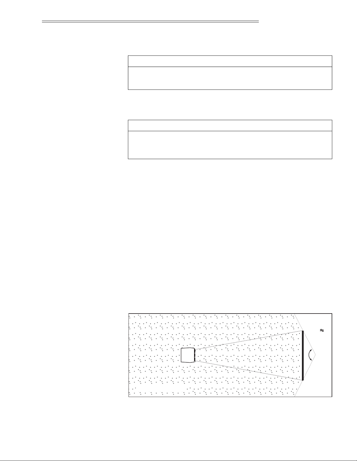
Flat screens offer a gain of about 1 with a viewing angle just less than 180°.
Incident light reflects equally in all directions so the audience can see the
display from various angles. Because of the lower gain, flat screens are more
effective when ambient lighting is reduced.
Figure 2-1. Audience Coverage with Flat Screen
.
Flat
Screen
(gain 1)
Viewing
Angle
Audience Coverage
ADVANTAGES CONSIDERATIONS
• Projector is completely hidden. • Requires separate room.
• Usually good ambient light rejection. • Installation cost is usually higher.
• Less space is required behind the screen
than other rear screen installations.
ADVANTAGES CONSIDERATIONS
• Projector is completely hidden from the audience. • Requires separate room.
• Usually good ambient light rejection. • Installation cost is usually higher.
INSTALLATION & SETUP
2.3
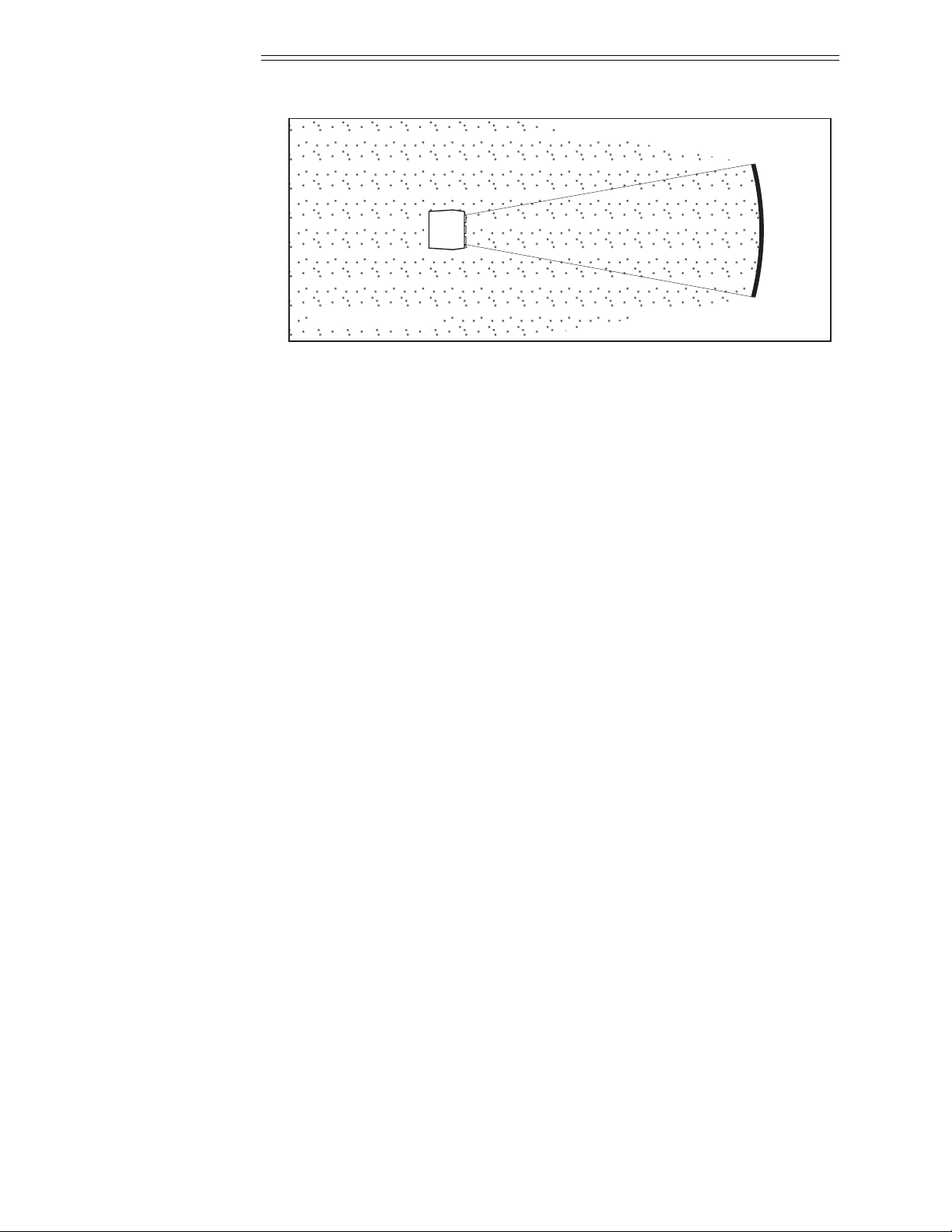
Figure 2-2. Audience Coverage with Curved Screen
Curved screens have gains larger than 1 and viewing angles much less than
180°. Most curved screens have different horizontal and vertical viewing
angles. Incident light does not reflect equally in all directions. The reflected
light concentrates in a conical volume or “viewing cone”. Audiences within
the viewing cone see a brighter image than that from an equal area on a flat
screen. Audiences outside the viewing cone see a dimmer image.
To summarize, curved screens are better suited for brightly lit rooms where
the audience is situated within the viewing cone. Flat screens are best suited
when a wide viewing angle is required and ambient room lighting (near the
screen) is low.
Note: Screen Gain is defined in Appendix A, Glossary.
Rear Screen Installations
There are two basic types of rear screens: diffused and optical. A diffused
screen has a surface which spreads the light striking it. Purely diffused
screens have a gain of less than 1. The main advantage of the diffused
screen is its wide viewing angle, similar to that of a flat screen for front
screen projection.
Optical screens take light from the projector and redirect it to increase the
light intensity at the front of the screen. This reduces it in other areas. A
viewing cone, similar to that of a curved front screen installation, is created.
To summarize, optical screens are better suited for brightly lit rooms where
the audience is situated within the viewing cone. Diffused screens are best
suited when a wide viewing angle is required but there is low ambient
room lighting.
Curved
Screen
(gain >1)
Audience Coverage
INSTALLATION & SETUP
2.4

Screen Size and ➤
Throw Distance
Screen size and throw distance are interrelated. (See Appendices F and G.)
As screen size increases, the distance between the projector and the screen
also increases. During projection room design, make sure that the room
can accommodate the required position of the projector for the screen size
you need.
Screen Size
Screen sizes vary according to model and lens type. (See Appendices F
and G.) Choose a screen size which is appropriate for your application. If
the projector will be used to display text information it is important that
the image size allows the audience to clearly resolve all text. The eye usually
sees a letter clearly if eye-to-text distance is less than 150 times the height of
the letter. Small text, located too far from the eye, may not be legible at a
distance even though it is projected sharply and clearly on the screen.
To fill a screen with an image, the aspect ratio of the screen must be equal
to the aspect ratio of the image. The aspect ratio of an image is the ratio of
its width to its height. Standard video from a VCR has a 4:3 or 1.33:1
aspect ratio. For example, to display a VCR output with a 4:3 aspect ratio
onto a 10 foot (3m) high screen, the width of the screen must be at least
13.3 feet (4m).
Note: Screen size is often specified as diagonal size. Screens specified by diagonal
size have aspect ratios of 4:3. Screens with other aspect ratios are not typically
specified by diagonal size.
Throw Distance
The throw distance (projector-to-screen distance) must be determined for
every new installation. Throw distance, the distance between the projector’s
center lens and the center of the screen, is based on screen size. As screen
size increases, the distance between the projector and the screen increases.
Make sure that the room can accommodate the required position of the
projector for the chosen screen size.
Once your screen size is known you can determine the required throw distance for your projector model and lens by using the formulas in Appendix
G and tables in Appendix F.
Notes: 1) Calculated values are for reference only. It is good practice to simulate
the setup to determine the necessary throw distance. 2) Display size is affected by
input signal characteristics. Once the projector is set, use the Size function to fine
tune display size.
Throw distance and projection angle: Keep in mind that the ability to
properly focus all areas of the image is limited if a significantly tilted
projector is too close to the screen.
INSTALLATION & SETUP
2.5
Lighting ➤ Proper lighting is another important factor when designing a projection
room. Visiting a movie theatre can give you an idea of what makes a good
projection environment. All walls, floors and furnishings are dull colored
and non-reflectively finished. Every effort should be made to create the best
environment for your system.
When designing a projection room, try to avoid white, reflective ceilings
and non-directional lighting such as fluorescent lights. The white ceiling
spreads the light which makes the room appear brighter. You want to keep
the lighting and reflections to a minimum. Spot lighting is a better way to
obtain illumination. Installing light dimmers allows you to control your
lighting environment.
Outside windows are undesirable in any projection environment. A small
crack between curtains on a sunny day can severely wash-out an image.
Make sure that curtains are opaque and fit snugly. Some curtains can provide up to 100 percent blockage of outside light. Pay close attention to the
curtain material facing inside the room. It should have a matte finish.
Even with no external light at all, reflections from room surfaces can
degrade the image. Light from the screen should be absorbed by surfaces so
that it will not be reflected back to the screen. Keep reflective surfaces to a
minimum.
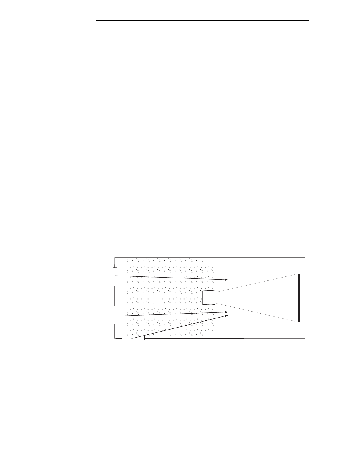
To minimize the effects caused by unwanted light from door and aisle ways,
carefully choose the position of your projector and screen. Figure 2-3 shows
an installation where poor screen placement has allowed too much unwanted
light to enter the screen. In Figure 2-4, the screen and the projector are
positioned so that unwanted light is minimized.
Figure 2-3. Poor Screen Placement
Prime Audience
Area
unwanted light
unwanted light
unwanted light
window
doordoor
INSTALLATION & SETUP
2.6
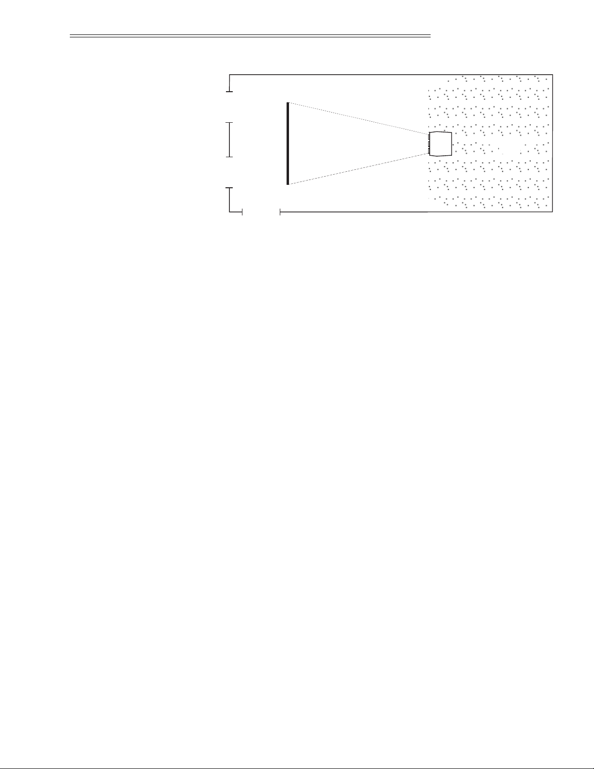
Figure 2-4. Good Screen Placement
Other ➤
Considerations
Here are some other considerations and tips which can help you improve
the design of your projection system.
❑ Proper ventilation is important. The ambient temperature should be kept
constant and below 35° C (95° F). Keep the projector away from heating
and/or air conditioning vents. Changes in temperature can cause drifts in
the projector circuitry which may affect performance.
❑ Keep the projector away from devices which radiate electromagnetic
energy such as motors and transformers. Common sources of these
are slide projectors, speakers, power amplifiers, elevators, etc. Keep 35
mm slide projectors at least 2 feet away from the projector. Even if both
are not used at the same time, the magnetic fields created by the slide
projector can cause permanent magnetization of the projector.
❑ For rear screen applications, less space is required if a mirror is used to
fold the optical path.
❑ Choose the right screen size for your application:
• As screen size increases, magnification increases which reduces brightness. This reduces the contrast ratio which affects legibility. Sharp
defined edges become soft and fuzzy. Consider whether screen size is
more important than these other vital picture characteristics.
• Installing a large screen in a small room is similar to watching television close up; too large a screen can overpower a room. A good rule
of thumb is to be no closer than two times the height of the screen.
• Larger screens require greater attention to lighting conditions.
❑ When laying out your projection room, consider positioning the projector
and screen in a manner which will achieve maximum audience coverage
and space efficiency. For example, placing the screen along the larger wall
in a rectangular room will reduce audience coverage. Figure 2-5 shows two
examples of how audience coverage is maximized.
window
doordoor
Prime Audience
Area
INSTALLATION & SETUP
2.7
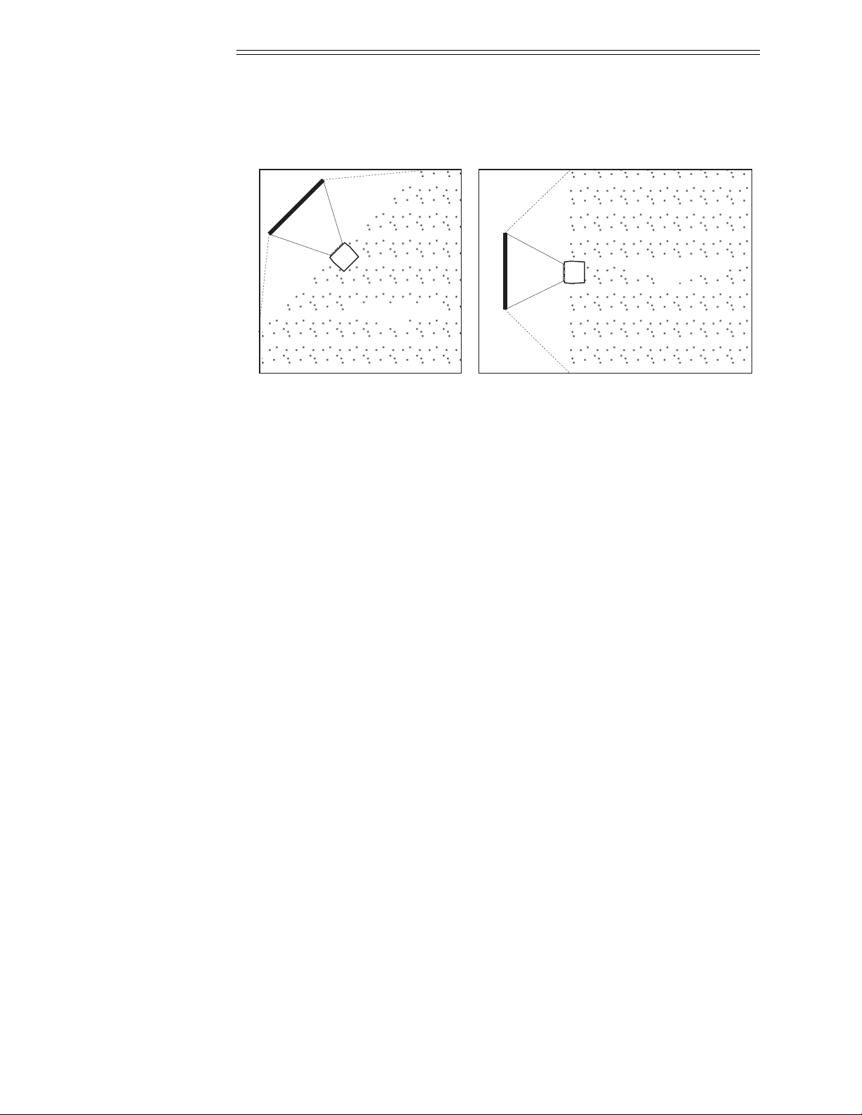
Figure 2-5. Screen Locations for Maximum Audience Coverage
2.3 Hardware
Setup
This section explains: how to convert the keypad from a built-in keypad to
a remote keypad, how to change keypad protocol and backlit settings, and
how to determine if reverse scan setup is required.
Keypad ➤
Conversion
The projector includes a multi-use full-function keypad which may be
configured for use as a built-in, IR remote, or wired remote keypad. The
keypad is configured at the factory for built-in use. It is located below the
front top cover. You can use the keypad as it is or re-configure it for
remote operation. You can also “hard wire” the keypad to be a protocol A
or protocol B keypad (see section 3.7, Utility Features for information
about keypad protocols).
Prime Audience
Area
Corner placement of screen
yields best audience coverage.
SQUARE ROOMS
Screen placement along short
wall yields best audience coverage.
RECTANGULAR ROOMS
Prime Audience
Area
INSTALLATION & SETUP
2.8
Follow the steps below to convert the keypad to a remote keypad and
change its protocol setting.
Step 1
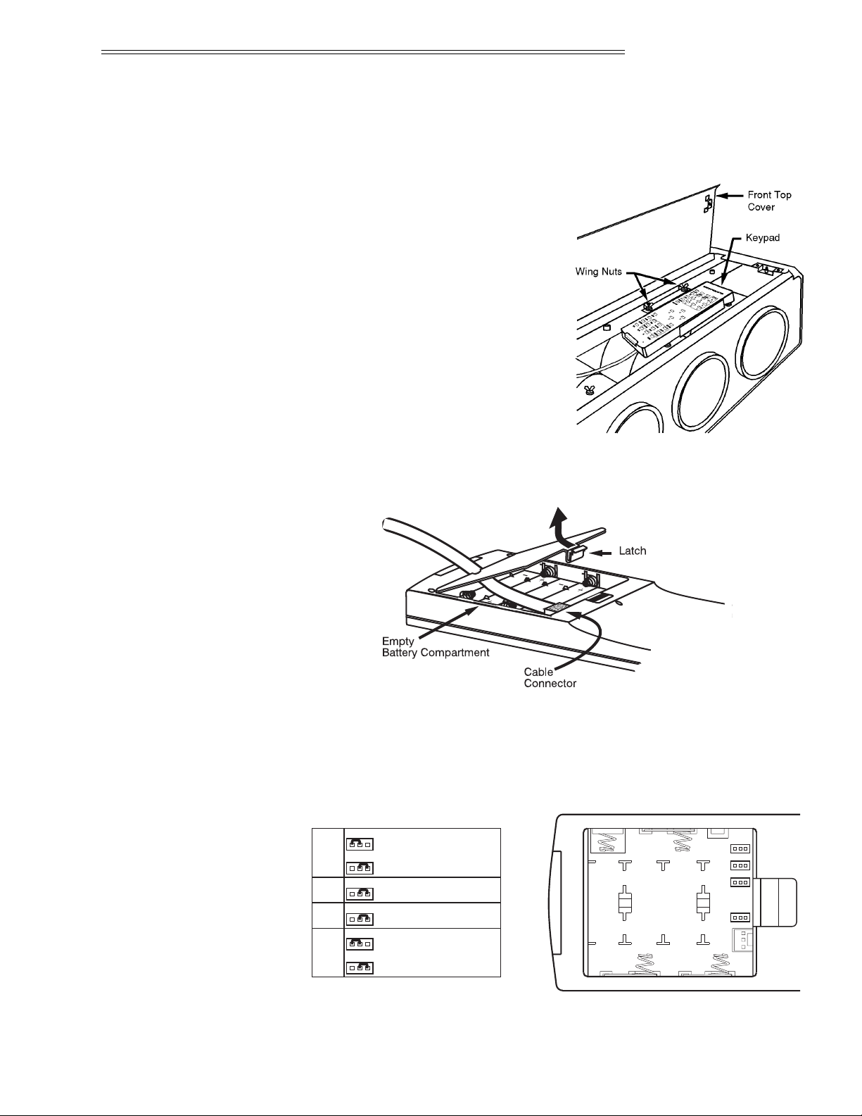
Unplug the projector then lift the
front top cover to access the built-in
keypad. To lift the cover, grasp it
above the red and blue lenses then lift
it until the keypad is exposed. The
keypad is mounted to a securing
bracket located above the lens assemblies. Loosen the two bracket wing
nuts then move the keypad away
from the bracket. See Figure 2-6.
Step 2
Locate the battery compartment at
the back side of the keypad. Squeeze
the latch to open the door. See
Figure 2-7.
Figure 2-6. Built-in Keypad Access
Figure 2-7. Battery Compartment
If converting the keypad to an IR remote, unplug the cable connector.
Locate the jumper wires next to the cable connector location. See Figure
2-8. The jumper wires control the keypad’s operating settings.
Figure 2-8. Jumper Settings
JP1
321
321
321
321
JP2
JP3
JP4
JP1
PROTOCOL A
PROTOCOL B
321
321
JP2
(ALWAYS)
321
JP3
(ALWAYS)
321
JP4
BUILT-IN OR
WIRED KEYPAD
IR REMOTE KEYPAD
321
321
INSTALLATION & SETUP
2.9

JP1
This jumper setting is important if the keypad is configured for remote
operation. There are two keypad protocols: A and B. These protocols are
available to allow two projectors in the same room to be independently controlled by separate remote keypads. The protocol setting of the keypad must
match that set in the projector’s Keypad Options menu ( ). For
more information about keypad protocols, refer to the Remote Control
Options entry in section 3.7, Utility Features.
JP2
This jumper must always be set between pins 1 and 2 as shown; otherwise,
the projector will not respond correctly to keypad commands.
JP3
This jumper must always be set between pins 1 and 2 as shown; otherwise,
the backlit feature will be disabled and the projector will not respond
correctly to keypad commands.
JP4
The JP4 jumper setting sets the keypad type. If you are converting the keypad to an IR remote, move the JP4 jumper from between pins 2 and 3 to
between pins 1 and 2.
Step 3
For an IR remote keypad, place four AA size, 1.5V alkaline batteries in the
compartment ensuring that the +/– orientation of each battery is correct.
Position the compartment door into place.
For a wired remote keypad, an optional accessory cable (#03-001106-02P)
is required. Plug the cable into the cable connector then position the door
into place. Plug the cable jack into the remote jack input on the projector.
WARNING: DO NOT INSTALL BATTERIES IN THE KEYPAD IF A
BUILT-IN OR WIRED REMOTE CABLE IS ATTACHED TO IT. THIS MAY
CAUSE THE BATTERIES TO EXPLODE.
Keypad Operating ➤
Settings
The keypad includes its own memory to store keypad operating settings. With
a few simple keystrokes you can over-ride the “hard wire” protocol setting
(explained earlier) and enable or disable the backlit feature. Keypad battery life
is increased if the backlit feature is disabled. The new operating settings are
stored in the keypad until the batteries are replaced (IR remote keypad) or the
keypad connection cable is unplugged (wired or built-in keypad).
7
6
UTIL
INSTALLATION & SETUP
2.10
If the keypad is configured for IR remote operation, make sure the batteries
are installed. If it is configured for built-in or wired remote operation, make
sure its extension cable is properly connected to the projector. Perform the
following keystroke sequences to change its operating settings:
• To toggle the keypad’s protocol setting (A or B),
press .
• To toggle the backlit feature (enable or disable),
press .
• To return all configuration settings to the jumper settings,
press .
Note: The projector will not respond to keypad commands if you press
. If pressed accidentally, press to clear
all keystroke settings.
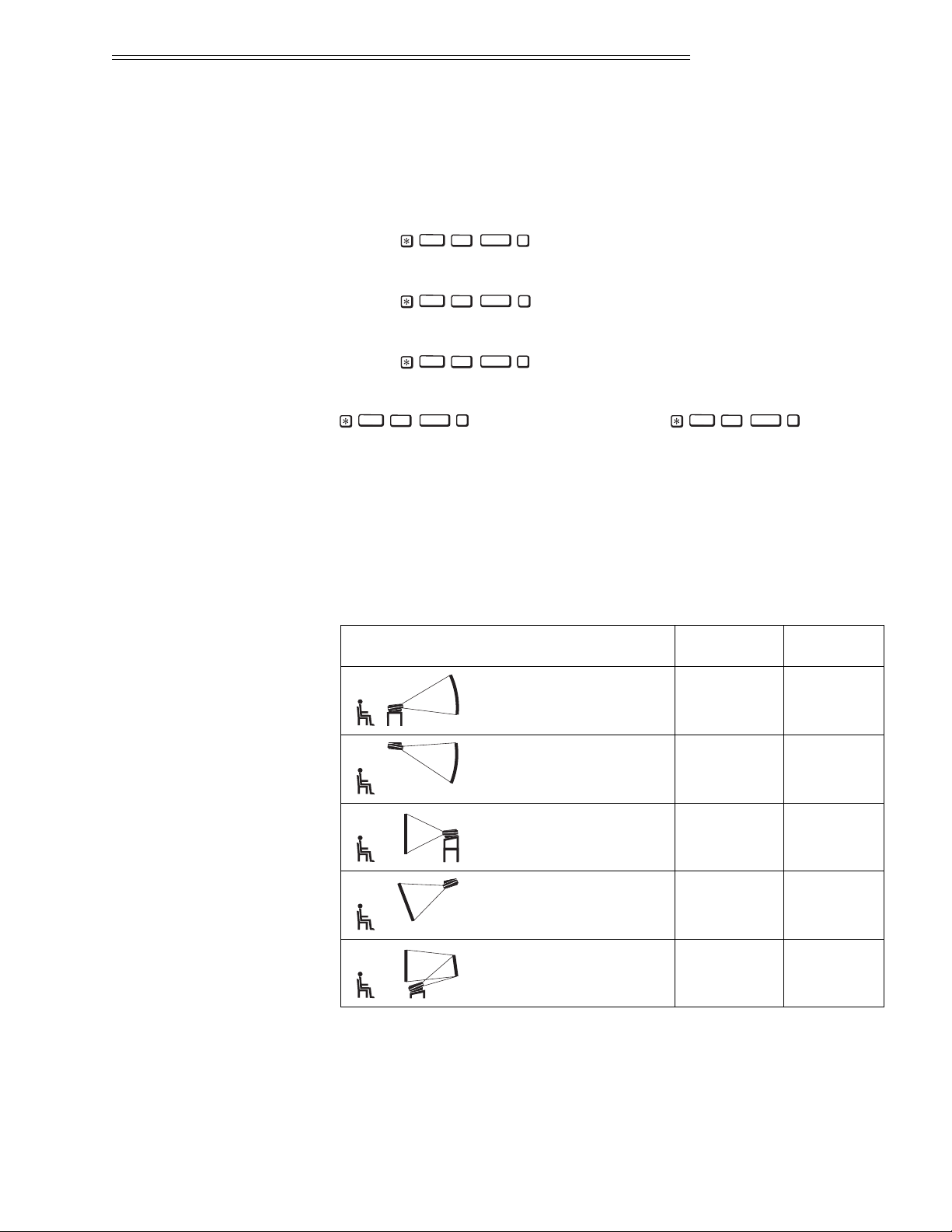
Reverse Scan ➤ If the projector is not installed in a front screen, floor mount configuration,
reverse scan setup may be required. Reverse scan setup must be performed by a
qualified Madrigal Imaging service technician. Refer to Table 2-2 to determine
if reverse scan setup is required. Contact your dealer for assistance.
Table 2-2. Operating Configurations
Rear Screen,
Floor Mount,
With Mirror
OPERATING CONFIGURATION
HORIZONTAL
SCAN
VERTICAL
SCAN
Front Screen,
Floor Mount
(default configuration)
Front Screen,
Ceiling Mount
Rear Screen,
Floor Mount
Rear Screen,
Ceiling Mount
NORMAL NORMAL
REVERSED REVERSED
REVERSED NORMAL
NORMAL REVERSED
NORMAL NORMAL
0
DETAIL
TINT
BRITE2DETAIL
TINT
BRITE0DETAIL
TINT
BRITE3DETAIL
TINT
BRITE1DETAIL
TINT
BRITE
INSTALLATION & SETUP
2.11
2.4 Mounting
The projector should be mounted after the system design has been
established and reverse scan setup (if required) is complete.
Front Screen ➤
Installations
Floor Mount
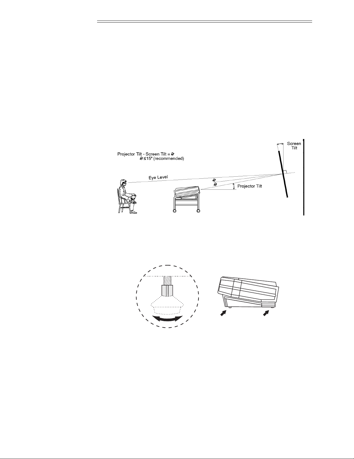
Mount the projector on a secured table or cart. Position the projector at the
chosen room location with the projector pointing towards the center of the
projection screen. The angle of projection, combined with the tilt angle of
the screen should direct the reflected image towards the center of the audience. It is recommended that the difference between the projection angle
and the screen tilt angle (within a common reference) be less than 15°.
Refer to Figure 2-9.
Figure 2-9. Floor Mount Installation
You can adjust projection angle and level by adjusting the height of the
projector legs. See Figure 2-10.
Figure 2-10. Leg Adjustment
Ceiling Mount
Mounting the projector to the ceiling requires the use of a projector ceiling
mount fixture. The fixture is shipped from the factory in kit form (with
assembly instructions) for assembly and installation by the dealer/installer.
For more information, contact your dealer or Madrigal.
INSTALLATION & SETUP
2.12
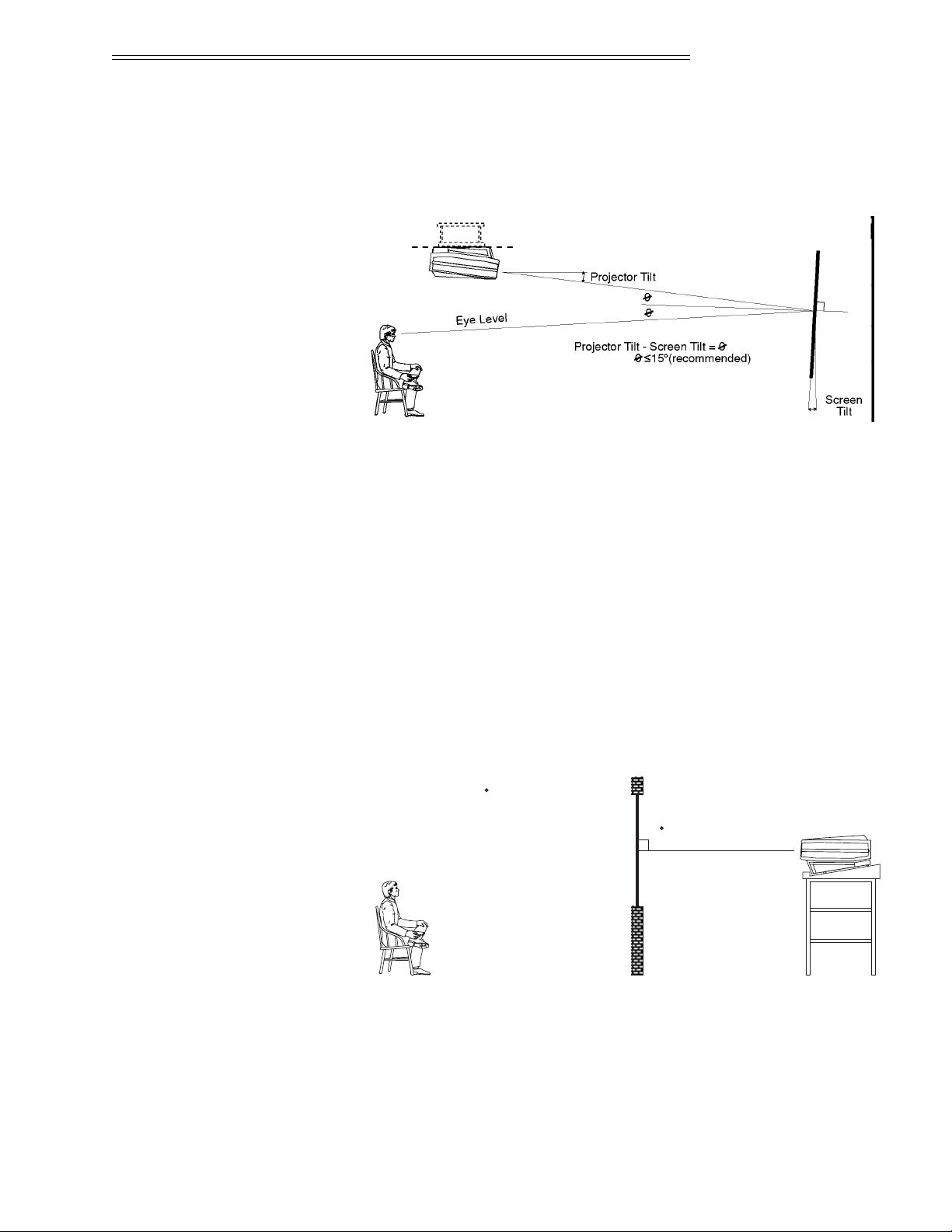
Position the projector so that it is pointing toward the center of the projection
screen. The angle of projection combined with the tilt angle of the screen
should direct the reflected image towards the center of the audience. It is recommended that the difference between the projection angle and the screen tilt
angle (within a common reference) be less than 15°. See to Figure 2-11.
Figure 2-11. Ceiling Mount Installation
Instructions for adjusting projection angle are provided with the fixture kit.
For more information, contact your dealer or Madrigal.
Rear Screen ➤
Installations
When installing a rear screen system, the vertical positioning of the projector is dependent on the type of rear screen being used. There are two basic
types of rear screens: optical and diffused.
Optical Rear Screen Systems
If the system includes an optical rear screen, mount the projector along the
center axis of the screen as shown in Figure 2-12.
Figure 2-12. Optical Rear Screen Installation
90
Projection Angle = 0
INSTALLATION & SETUP
2.13
Diffused Rear Screen Systems
If the system includes a diffused rear screen, floor mount or ceiling mount
the projector so that the image is directed to the center of the audience.
Projection tilt should be less than 15°. See Figure 2-13.
Figure 2-13. Diffused Rear Screen Installation
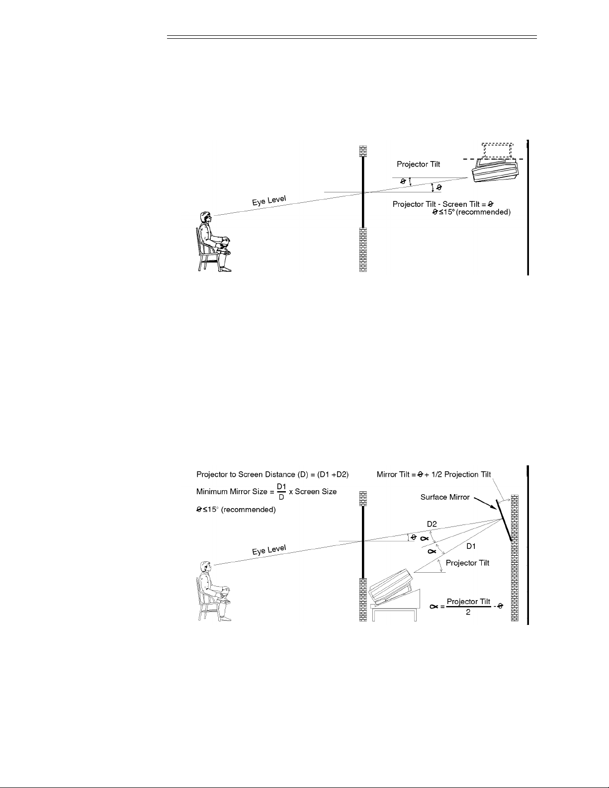
In situations where the space behind the projector is limited, a mirror may
be used to fold the optical path as illustrated in Figure 2-14. If a diffused
screen is used, the projection angle Ø should be less than 15°. If an optical
screen is used, the optical path between the mirror and the screen should be
perpendicular to the screen. Much attention must be given to the positioning of the projector and the mirror. This can be quite difficult for installers
unfamiliar with this type of installation. It is recommended that your dealer
or an experienced installer perform the installation.
Note: When using a mirror as shown in Figure 2-14, the calculated throw
distance (D) is the summation of D1 and D2.
Figure 2-14. Folded Optics
INSTALLATION & SETUP
2.14
2.5 Power
Connection
To apply power to the projector, plug
the AC line cord into the line input
socket located at the front panel of
the projector. Plug the three prong
end of the line cord in a grounded
AC outlet. Input voltage to the projector must be between 90 and 264
VAC, 50 or 60 Hz. The power source
must supply 650 watts of power to
the projector.
Figure 2-15. Power Connection
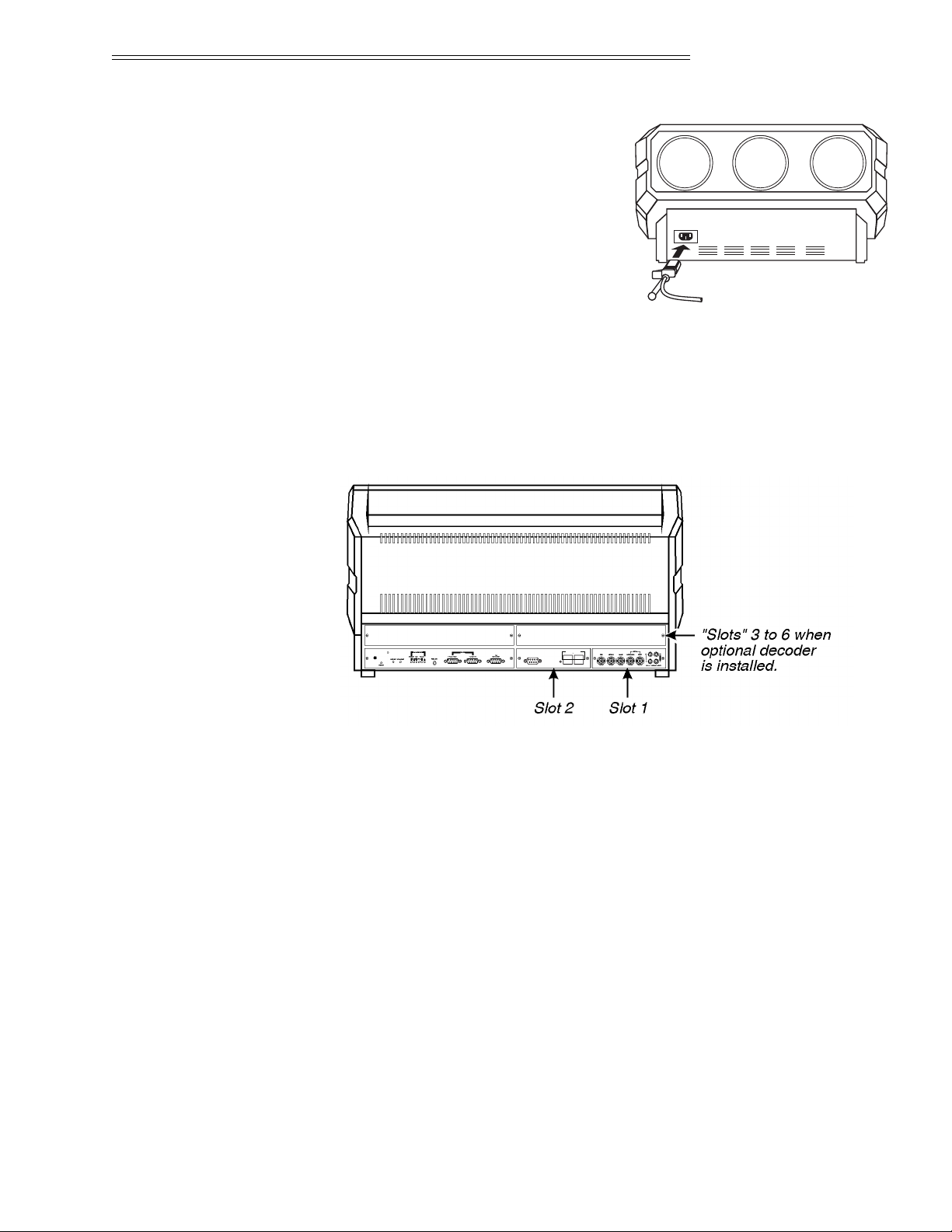
2.6 Source
Connections
The projector includes a built-in RGB input interface for connection of
external RGB sources and audio equipment. This input interface is shown
in Figure 2-16. The built-in interface is not removable.
Figure 2-16. Projector Input Slots
Optional interface modules are available to accommodate other signal
types. These include a Composite/S-Video Module, an HDTV Input
Module, and a PC Analog Input Module. Any one of these can be installed
in slot 2. A Multi-Standard Decoder may be installed to add four additional
inputs to the system (“slots” 3 to 6). To further increase the number of
inputs, a signal switcher may be connected to the RGB interface in slot 1
to add 8 more sources to the system (9 switcher inputs replace one RGB
input). Other switchers may be connected to the first switcher for more
inputs. Brief descriptions of the above mentioned optional modules are
given in Appendix H, Interfaces. For additional details, contact your dealer
or Madrigal.
to projector's
RS-232 in port
control ports
PHASTLink compatible
90 - 264 VAC
50 - 60 Hz
INSTALLATION & SETUP
2.15
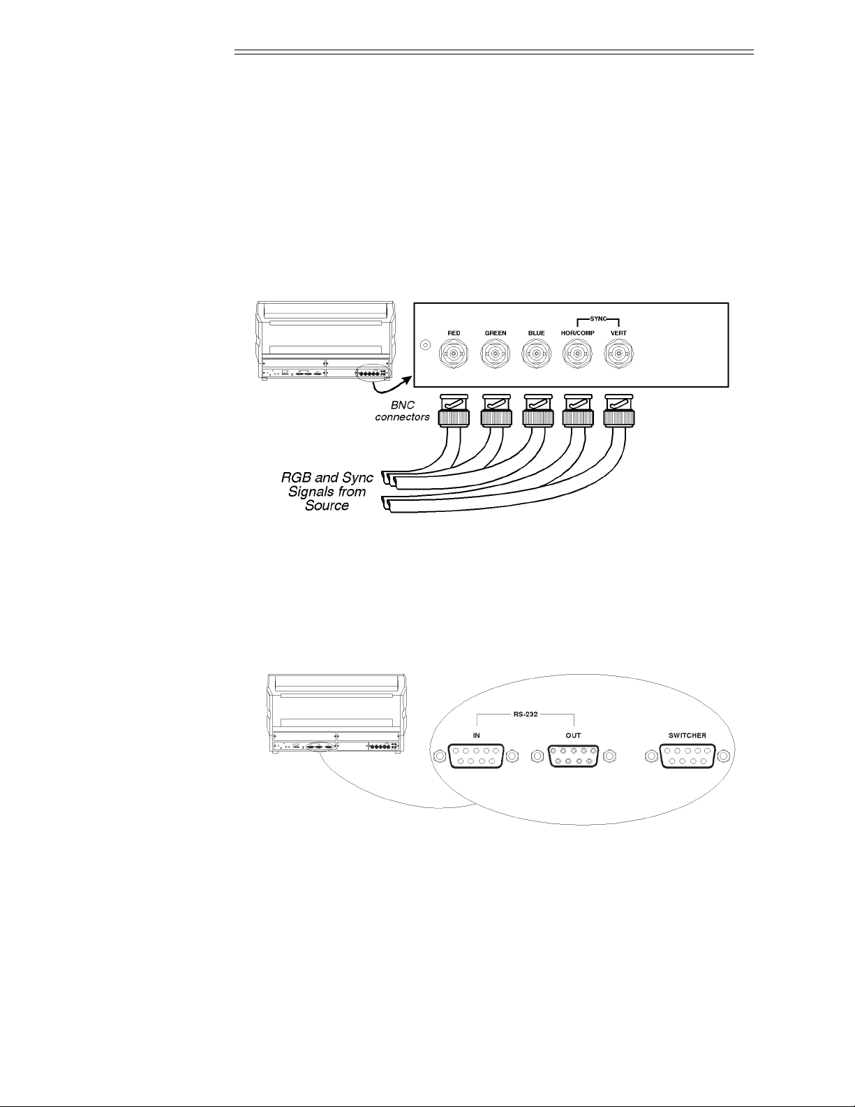
The RGB interface allows connection of an RGB source having one of the
following sync types: sync on green, composite sync, or separate H & V sync.
To connect a source, connect the red, green, and blue outputs to the RED,
GREEN, and BLUE inputs on the interface. If the source uses sync on green,
no additional cables are required. If the source provides a composite sync output, connect it to the HOR/COMP input. If the source provides separate
horizontal and vertical sync outputs, connect the horizontal sync signal to the
HOR/COMP input, and connect the vertical sync input to the VERT input.
Interconnection cables must be terminated with BNC connectors. Figure 2-17
show source connections for the built-in interface.
Figure 2-17. Built-in RGB Interface Connections
2.7 Serial Port
Connections
Serial port connections are required when the projector is to be controlled
by a computer/controller other than PHAST.
The projector’s serial ports are located on the back panel. See Figure 2-18.
Figure 2-18. Serial Port Connections
If the projector is to be controlled by a computer or controller which has an
RS-232 serial port, connect an RS-232 serial cable between the computer
and the projector serial port labeled “IN”. After the connection is made, set
the serial port baud rate as described in the Projector Setup entry in section
3.7, Utilities.
INSTALLATION & SETUP
2.16
Notes: 1) All serial connections require a 9 pin D connector at the projector end.
Refer to Appendix D for cable wiring requirements. 2) For computer/controller
control, PC software is required. 3) The RS-232 serial port labeled “OUT” is
provided for projector networking applications.
2.8 Optical
Alignment
Optical alignment is required when the throw distance changes or the projector cannot be focused using the focus controls. The projector is optically
aligned at the factory at a fixed screen size and a fixed projector-to-screen
distance. See Appendices F and G for the specific details needed for your
projector model and lens. If the throw distance has changed since the last
setup, proceed as follows:
Notes: 1) The projector must be warmed up for at least 45 minutes prior to
performing optical alignment. 2) Optical alignment is both a mechanical and
electrical adjustment. Electrical adjustments are stored in the current setup
memory. After alignment is complete, setup memories which were previously set
up (if any) must be set up again. Memory setup is explained in section 2.10. 3)
Factory alignment is performed using the internal crosshatch with a 61.8 kHz
signal applied.
It is recommended that optical alignment be performed using the projector’s
Guided Mechanical Setup tutorial. This tutorial displays step-by-step
instructions during the alignment. The instructions in this section require
use of the Guided Mechanical Setup tutorial.
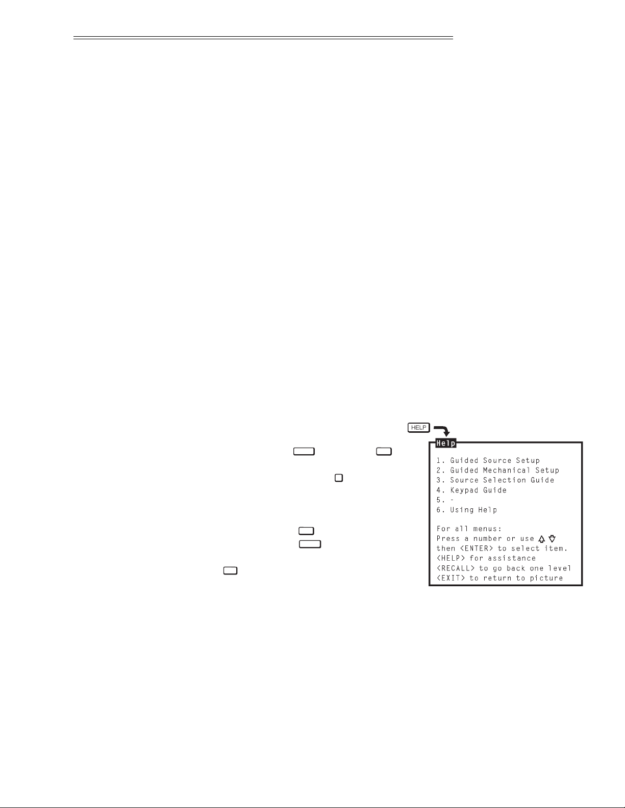
To access and use the Guided
Mechanical Setup tutorial, turn on
the projector ( ) then press
at operation level. The Help menu
is displayed. Next press to select
Guided Mechanical Setup. The first
page of the guide will be displayed on
the projection screen. When using
the guide, press to display the
next page, press to display the
previous page. When complete, press
to end Help.
Step 1
➤
If you have not already done so, calculate the throw distance and set the
projector position as explained in section 2.4, Mounting. Turn power off
before moving the projector.
EXIT
RECALL
HELP2HELP
POWER
INSTALLATION & SETUP
2.17
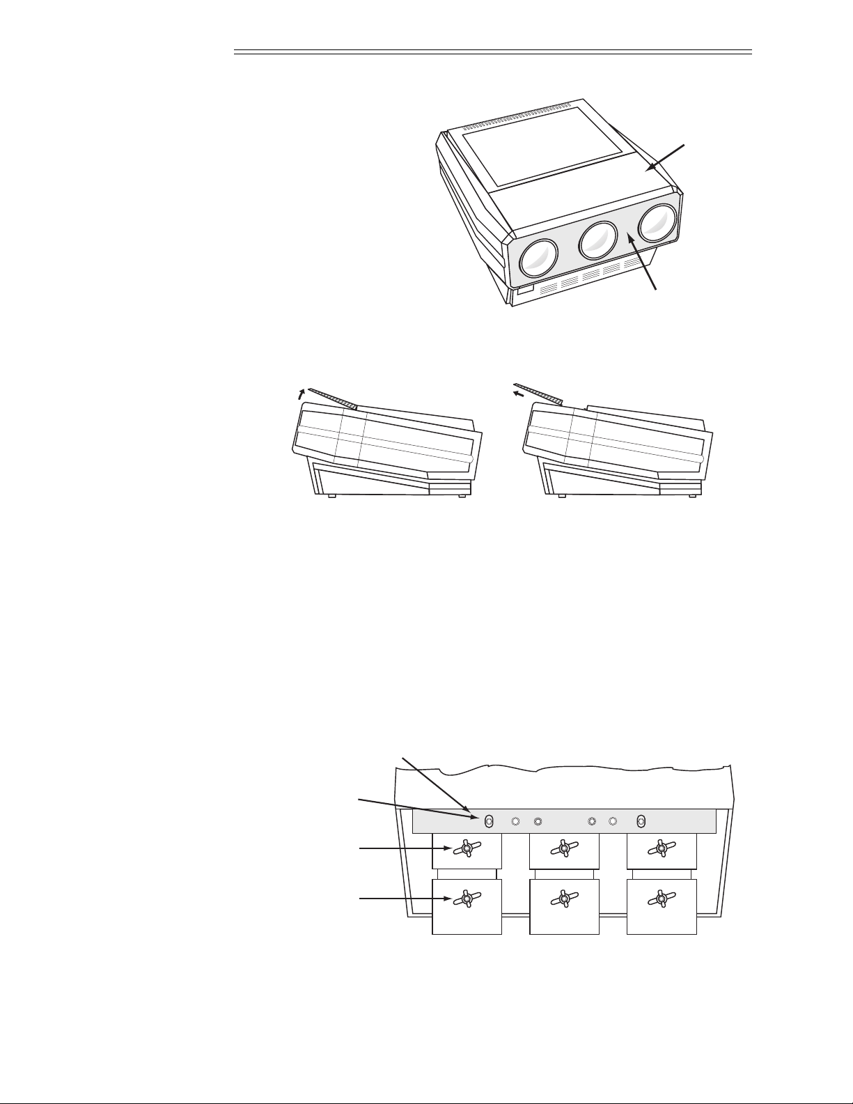
Step 2 ➤ Locate the front top
cover of the projector.
See Figure 2-19. Next,
position your hands above
the red and blue lenses
then grasp the cover.
Gently lift it until it is
released from its securing
latch. Slide the cover away
from the projector as shown
in Figure 2-20 below.
Figure 2-19. Front Top Cover
Figure 2-20. Front Top Cover Removal
Also remove the black decorative foam piece at the front of the lenses
(removal is optional). Remove the large allen head driver from the tool kit
provided with the projector. The driver is used for lens alignment.
Examine the lenses and hardware as shown in Figure 2-21a (or, for the
MP-8 model, see Figure 2-21b). Each lens consists of a rear section and a
front section. The rear section sets the optical focus at the center of the
image and is secured to the lens body by a wing nut at the top rear of the
lens assembly. The front section sets the focus at the corners and is secured
to the rear section by a wing nut at the top front of the lens assembly.
Figure 2-21a. MP-9 Lens Assemblies - Top View
Center
Focus Adjust
Securing Bolts
Top Plate
Corner
Focus Adjust
Red
GreenBlue
C
C
D B
a) Lift front cover until
latch is released.
b) Slide cover forward.
Front Top
Cover
Foam Piece
INSTALLATION & SETUP
2.18
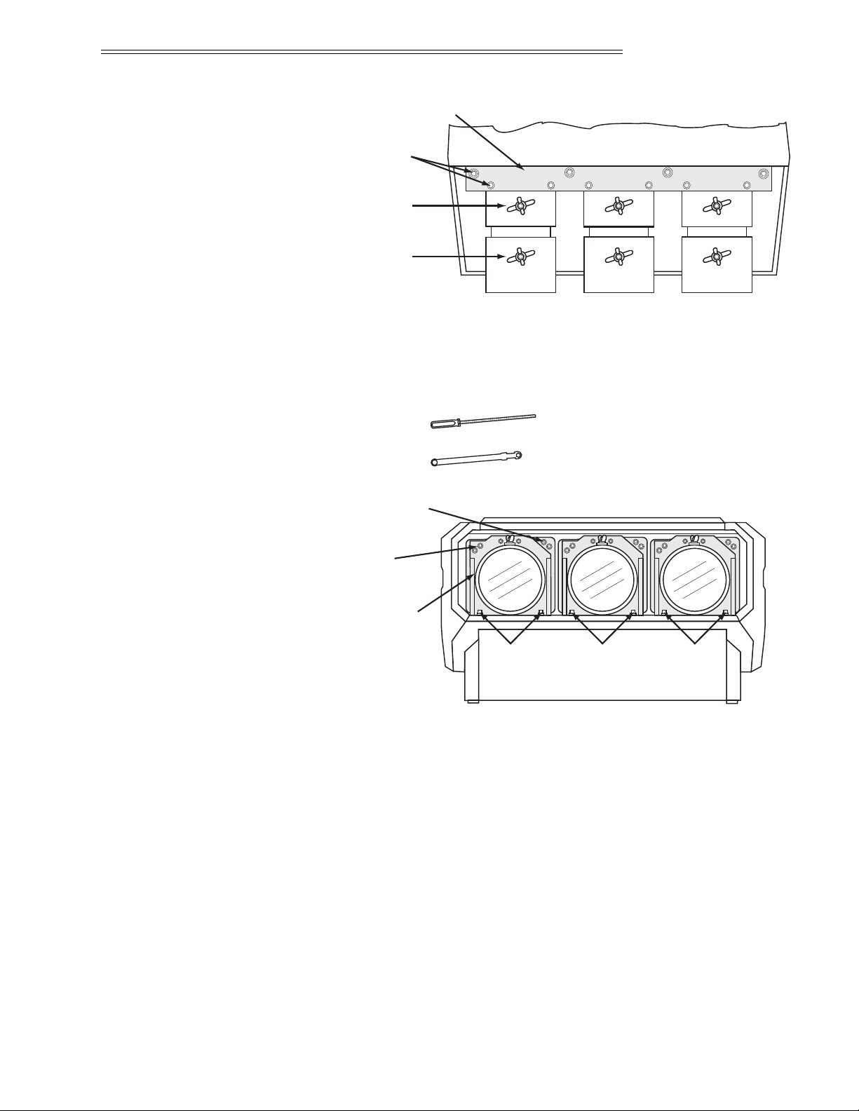
Figure 2-21b. MP-8 Lens Assemblies - Top View
For the MP-9: The lenses are secured to the projector frame by a top plate
and individual mounting plates as shown in Figures 2-21a and 2-22a.
During optical alignment, adjust the top plate securing bolts using the ball
nose screw driver ( ) supplied with the projector. Adjust the
mounting plate securing bolts using either the ball nose screwdriver or the
projector wrench ( ) supplied, as necessary. The securing bolts
are labeled B-C-D.
Figure 2-22a. MP-9 Lens Assemblies - Front View
For the MP-8: The lenses are secured to the projector frame by a top plate as
shown. During optical alignment, adjust the securing bolts as instructed —
refer to Figures 2-21b and 2-22b. The securing bolts are labeled A-B-C-D.
Lens
Mounting
Plate
Left/Right
Focus Adjust
Top/Bottom
Focus Adjust
Red
GreenBlue
DCB
Center
Focus Adjust
Lens/CRT
Securing Bolts
Top Plate
Corner
Focus Adjust
A
DCBDCB
AA
A
Red
GreenBlue
INSTALLATION & SETUP
2.19
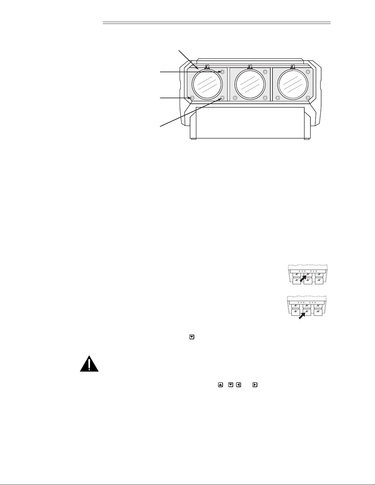
Figure 2-22b. MP-8 Lens Assemblies - Front View
For the MP-9, each CRT is attached to its lens by socket head allen screws
located at each lens mounting plate. For each lens, the upper left screws
(when facing the lens) adjust the focus between the left and right sides of
the picture, and the upper right screws adjust the focus between the top and
bottom of the picture. Use the supplied ball nose screw driver for these
adjustments.
For the MP-8, each CRT is attached to its lens by 3 socket head allen screws
located at each lens mounting plate. For each lens, the upper right screw
(when facing the lens) adjusts the focus between the top and bottom of the
picture, and the lower left screw adjusts the focus between the left and right
sides of the picture. See Figure 2-22b.
Step 3 ➤ Loosen the rear wing nut on the green lens. Rotate the lens
using the wing nut until the picture is focused in the center.
Tighten the rear wing nut.
Step 4 ➤ Loosen the front wing nut on the green lens. Rotate the
front lens barrel until the picture is focused in the corners.
Tighten the front wing nut.
Step 5 ➤ Steps 6 to 8 require that you look directly into the lenses for adjustment.
Before you continue, press to reduce contrast to a low level (less than
10%).
WARNING: DO NOT LOOK INTO THE LENSES IF CONTRAST IS SET
TO NORMAL VIEWING LEVEL.
Step 6 ➤ Look directly into the red lens. Press , , or to center the displayed
crosshatch on the face of the picture tube.
R
G
B
R
G
B
Lens Mounting Plate
Left/Right
Focus Adjust
Factory/Service
Adjust Only
Top/Bottom
Focus Adjust
Red
GreenBlue
INSTALLATION & SETUP
2.20
Step 7 ➤ Look directly into the green lens. Press , , or to center the
displayed crosshatch on the face of the picture tube.
Step 8 ➤ Look directly into the blue lens. Press , , or to center the
displayed crosshatch on the face of the picture tube.
Step 9 ➤ Press to increase contrast to a normal viewing level.
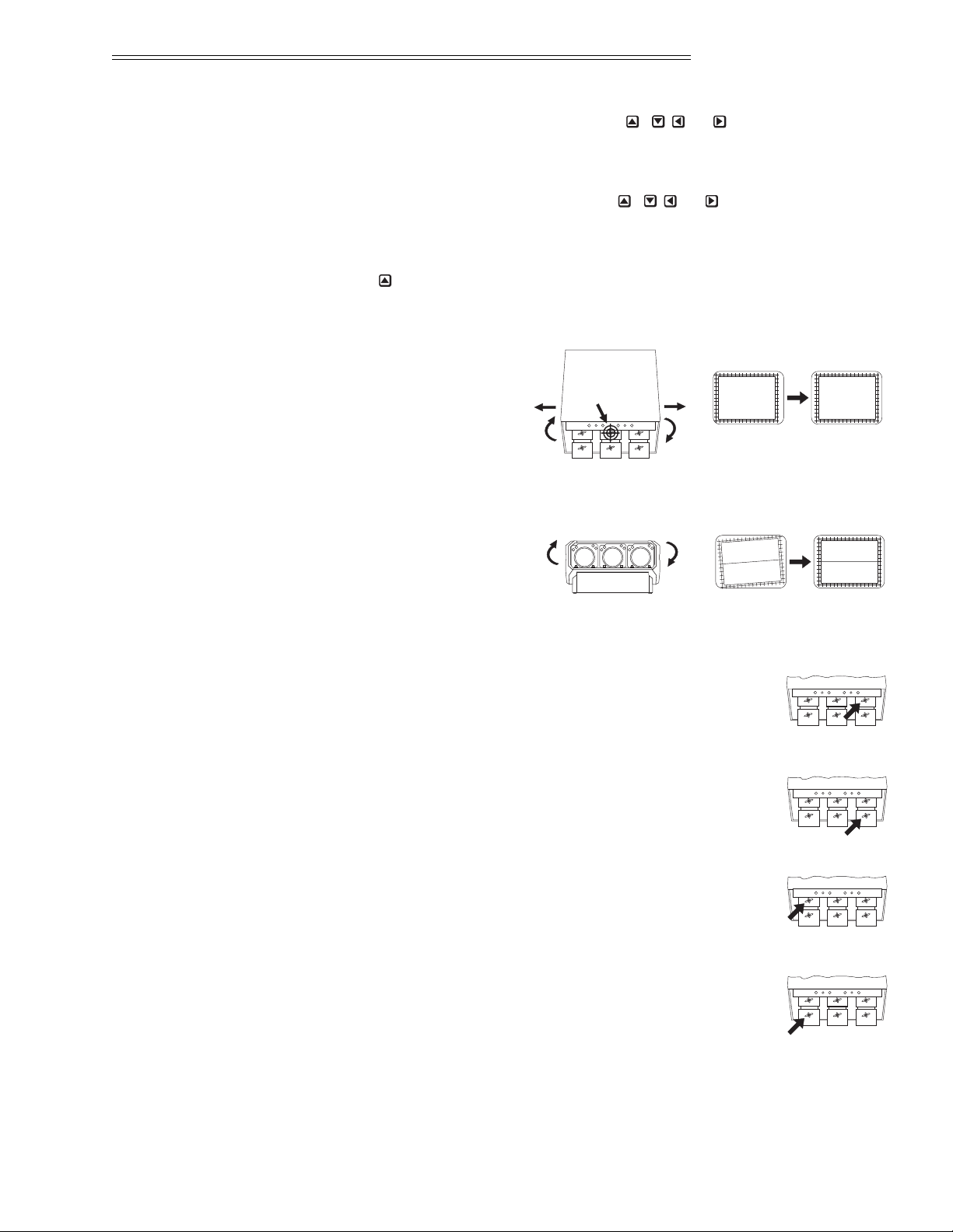
Step 10 ➤ Pivot the projector and
move it side to side as
necessary to display a
symmetrical crosshatch
centered left-to-right on
the screen. The pivot
point should be at the
rear wing nut of the green lens to avoid changing the throw distance.
Step 11 ➤ Tilt the projector until
the center horizontal line
is level and centered with
the screen. Adjust the feet
of the projector or ceiling mount as required.
Step 12 ➤ A red image is displayed. Loosen the rear wing nut on the
red lens. Rotate the lens using the wing nut until the picture
is focused in the center. Tighten the rear wing nut.
Step 13 ➤ Loosen the front wing nut on the red lens. Rotate the front
lens barrel until the picture is focused in the corners.
Tighten the front wing nut.
Step 14
➤
A blue image is displayed. Loosen the rear wing nut on
the blue lens. Rotate the lens using the wing nut until the
picture is focused in the center. Tighten the rear wing nut.
Step 15
➤
Loosen the front wing nut on the blue lens. Rotate the
front lens barrel until the picture is focused in the corners.
Tighten the front wing nut.
R
G
B
R
G
B
R
G
B
R
G
B
B RG
Before
After
pivot
point
Before
After
INSTALLATION & SETUP
2.21
Step 16
➤
Press or to adjust for best electrical focus at the center of the picture.
Step 17
➤
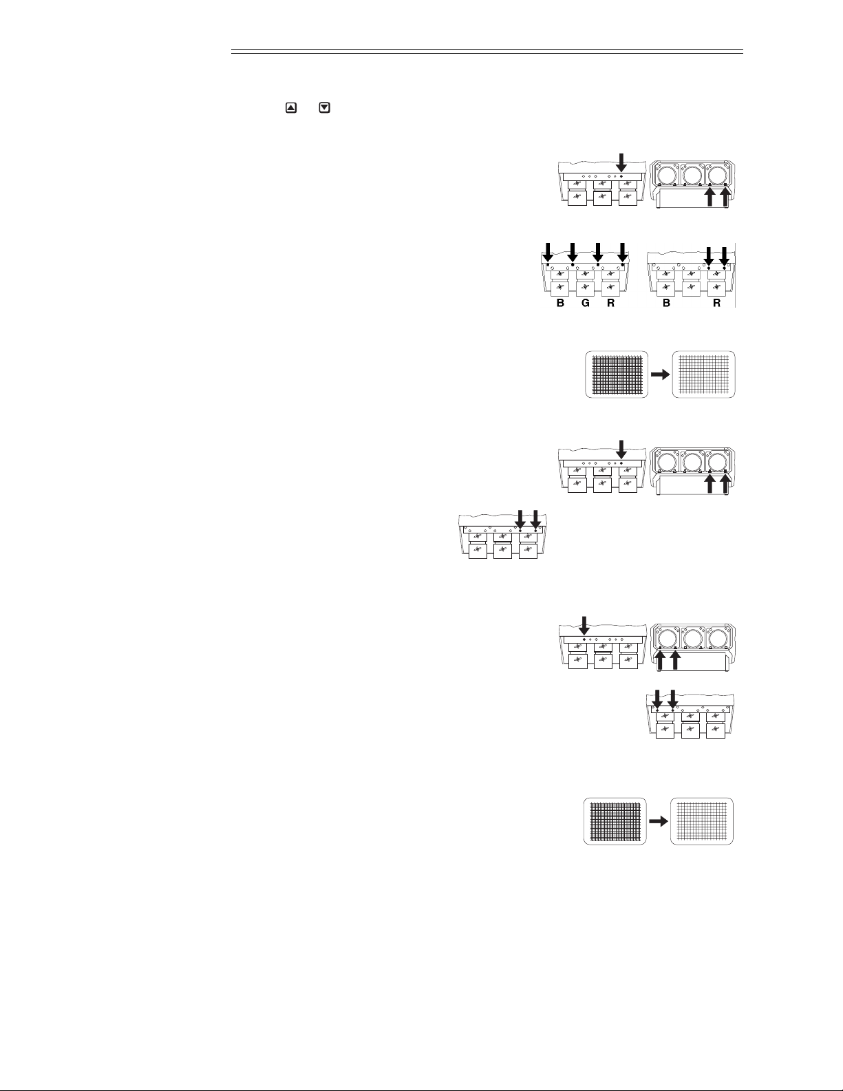
On the MP-9, loosen the three bolts labeled
“B”. One is located on the top plate. The
other two are below the red lens.
On the MP-8, loosen the four bolts
labeled “A”.
Loosen the two bolts labeled “B”.
Step 18 ➤ A red and green crosshatch is displayed. Move
the red lens so that the left and right edges of the
red crosshatch match the green.
Step 19 ➤ On the MP-9, tighten the three bolts
labeled “B”.
On the MP-8, tighten the two
bolts labeled “B”.
Step 20
➤
On the MP-9, loosen the three bolts
labeled “D”. One is located on the top plate.
The other two are below the blue lens.
On the MP-8, tighten the two bolts labeled “D”.
Step 21
➤
A blue and green crosshatch is displayed. Move the
blue lens so that the left and right edges of the blue
crosshatch match the green.
Before
After
R
G
B
B RG
R
G
B
R
G
B
B RG
R
G
B
Before
After
B RG
R
G
B
INSTALLATION & SETUP
2.22
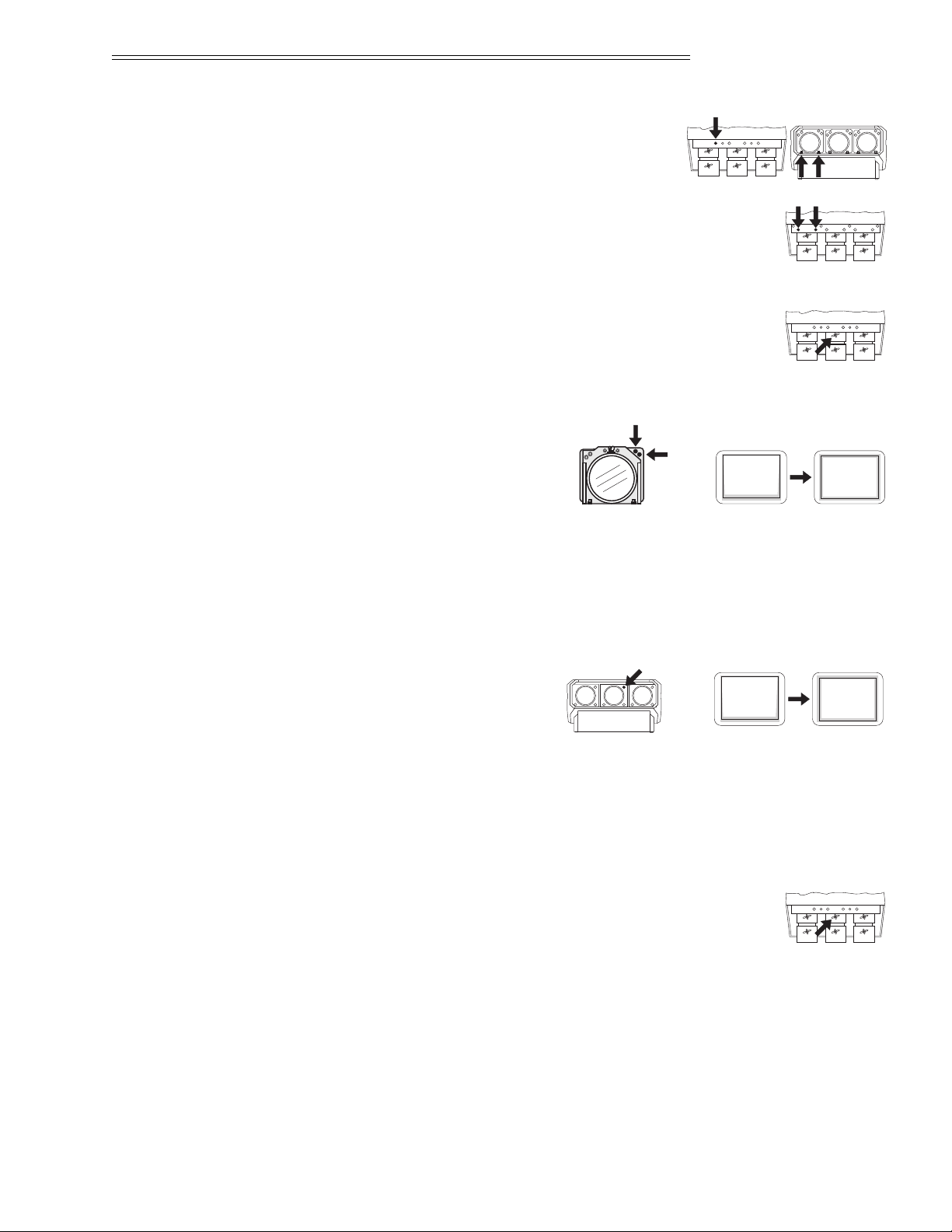
Step 22
➤
On the MP-9, tighten the three bolts
labeled “D”.
On the MP-8, tighten the two bolts labeled “D”.
Step 23
➤
A green image is displayed. Loosen the rear wing nut on the
green lens and slightly defocus the center of the picture.
Step 24 ➤ On the MP-9, locate the two
adjustment bolts at the upper
right corner of the green lens
mounting plate (viewed from
the front). Adjust the two bolts
until the top and bottom areas
of the picture are equally defocused. Use the following technique for the
adjustment: Turn the SIDE bolt
1
⁄
8 turn CCW. Turn the TOP bolt about
1
⁄
8
turn CW until it stops. If defocus at the top and bottom are equalizing,
repeat until equal. If the top and bottom are not becoming equally defocused, use the same technique but instead turn the TOP bolt CCW then
turn the SIDE bolt CW until it stops. Repeat until defocus is equal.
On the MP-8, adjust the
large allen head bolt located
at the upper right corner of
the green lens mounting plate.
Turn the bolt head until the top and bottom areas of the picture are
equally defocused.
NOTE: On all models, it may be necessary to readjust the lens’ rear wing nut to
keep the center defocused.
Step 25 ➤ Rotate the green lens using the rear wing nut until the
picture is focused in the center. Tighten the rear wing nut.
If necessary, loosen the front wing nut, rotate the front lens
barrel to readjust the focus in the corners, then re-tighten the wing nut.
R
G
B
R
G
B
Before
After
Before
After
SIDE
Bolt
TOP Bolt
G
R
G
B
R
G
B
B RG
R
G
B
INSTALLATION & SETUP
2.23
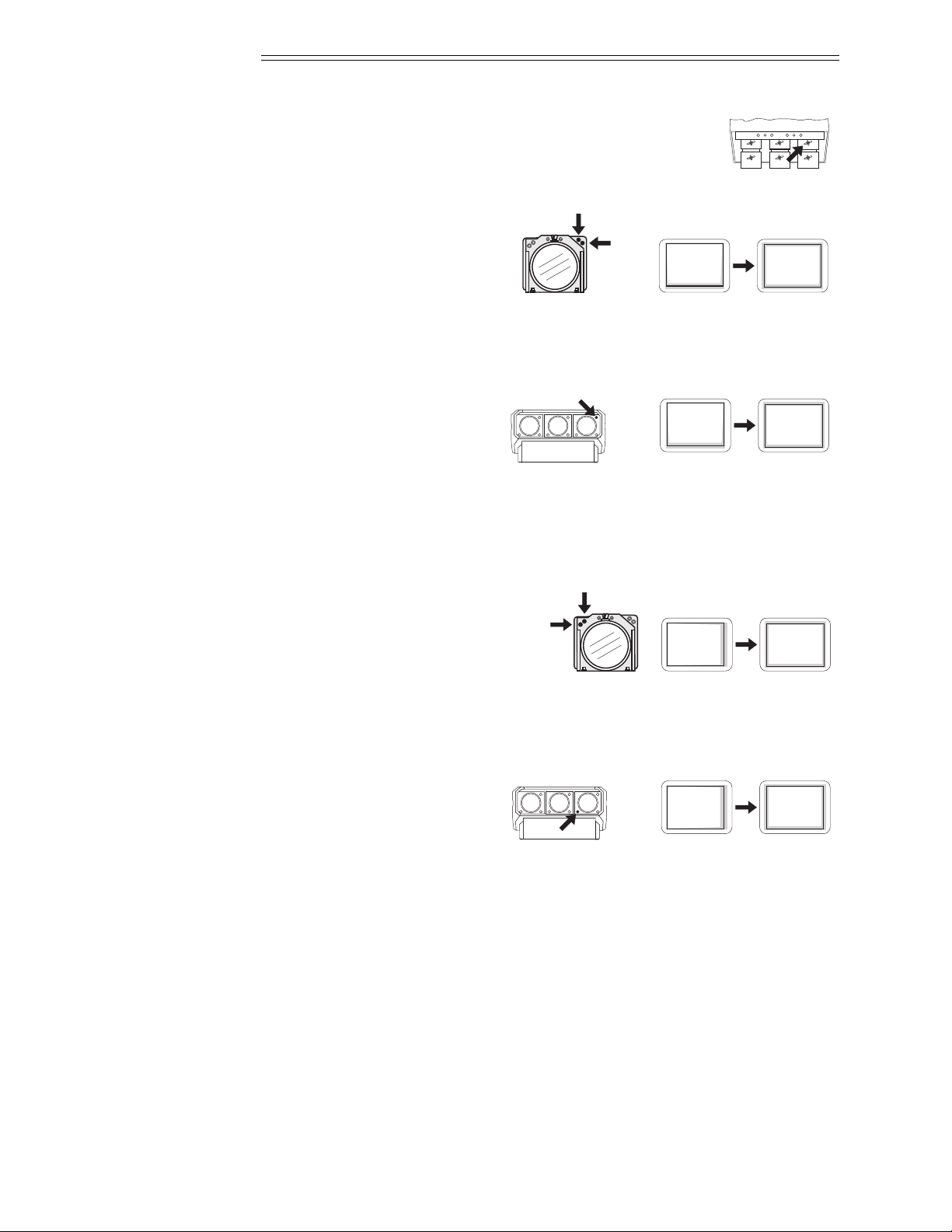
Step 26 ➤ A red image is displayed. Loosen the rear wing nut on the
red lens and slightly defocus the center of the picture.
Step 27 ➤ On the MP-9, locate the two
adjustment bolts at the upper
right corner of the red lens
mounting plate (viewed from
the front).
Adjust the two bolts until the top and bottom areas of the picture are
equally defocused. Use the same technique as that used for the green
adjustment (step 24).
On the MP-8, adjust the large
allen head bolt located at the
upper right corner of the red
lens mounting plate. Turn the
bolt head until the top and bottom areas of the picture are equally defocused.
Note: On all models, it may be necessary to readjust the lens’ rear wing nut to
keep the center defocused.
Step 28 ➤ On the MP-9, locate the two
adjustment bolts at the upper
left corner of the red lens mounting plate (viewed from the front).
Adjust the two bolts until the
left and right areas of the picture are equally defocused. Use the same
technique as that used for the previous adjustment (step 27).
On the MP-8, adjust the large
allen head bolt located at the
lower left corner of the red
lens mounting plate. Turn the
bolt head until the left and right sides of the picture are equally defocused.
Note: On all models, it may be necessary to readjust the lens’ rear wing nut to
keep the center defocused.
Step 29 ➤ Rotate the red lens using the rear wing nut until the picture is focused in
the center. Tighten the rear wing nut. If necessary, loosen the front wing nut,
rotate the front lens barrel to readjust the focus in the corners, then re-tighten
the wing nut.
R
G
B
Before
After
Before
After
SIDE
Bolt
TOP Bolt
R
R
G
B
Before
After
Before
After
SIDE
Bolt
TOP Bolt
R
R
G
B
INSTALLATION & SETUP
2.24
 Loading...