

MadgeTech VTMS-60, VTMS-72, VTMS w/ 30ml Glycol Bottle, VTMS w/ 250ml Glycol Bottle User manual
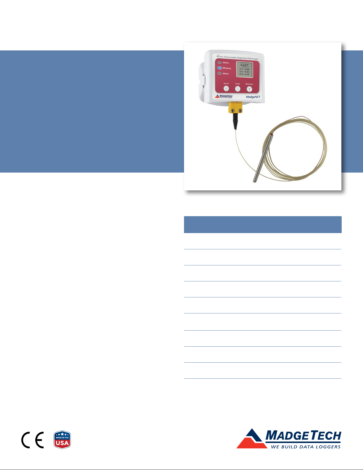
VTMS
Vaccine Temperature
Monitoring System
PRODUCT
USER GUIDE
TABLE OF CONTENTS
2 Quick Start Steps
3 Product Overview
4 Software Installation
5 Activating & Deploying the Data Logger
5 Channel Programming
6 Product Maintenance
7 Troubleshooting
8 Compliance Information
9 Need Help?
Find Quality Products Online at: sales@GlobalTestSupply.com
www.GlobalTestSupply.com
VTMS
QUICK START STEPS
Product Operation
(Wireless)
Install the MadgeTech 4 Software and USB Drivers
1
onto a Windows PC.
Connect the RFC1000 wireless transceiver (sold
2
separately) to the Windows PC with the provided
USB cable.
Push and hold the wireless button on the VTMS for
3
5 seconds to activate wireless communication. The
display will confirm “Wireless: ON” and the blue LED
will blink every 15 seconds.
Launch the MadgeTech 4 Software. All active
4
MadgeTech data loggers that are within range
will automatically appear in the Connected
Devices window.
Select the data logger within the Connected
5
Devices window and click the Claim icon.
Select the start method, reading interval and any
6
other parameters appropriate for the desired data
logging application. Once configured, deploy the
data logger by clicking Start.
Product Operation
(Plugged In)
Install the MadgeTech 4 Software and USB Drivers
1
onto a Windows PC.
Confirm the data logger is not in wireless mode. If
2
wireless mode is on, press and hold the Wireless
button on the device for 5 seconds.
Connect the data logger to the Windows PC with
3
the provided USB cable.
Launch the MadgeTech 4 Software. The VTMS will
4
appear in the Connected Devices window indicating
the device has been recognized.
Select the start method, reading rate and any
5
other parameters appropriate for the desired data
logging application. Once configured, deploy the
data logger by clicking the Start icon.
To download data, select the device in the list,
6
click the Stop icon, and then click the Download
icon. A graph will automatically display the data.
To download data, select the device in the list,
7
click the Stop icon, and then click the Download
icon. A graph will automatically display the data.
Find Quality Products Online at: sales@GlobalTestSupply.com
www.GlobalTestSupply.com
Product User Guide | 2
VTMS
PRODUCT OVERVIEW
The VTMS is a wireless vaccine temperature monitoring system, featuring a convenient LCD screen to display current
readings, minimum, maximum and average statistics, battery level and more. User programmable alarms can be
configured to activate an audible buzzer and LED alarm indicator, notifying the user when the temperature levels are
above or below the user set threshold. Email and text alarms can also be configured allowing users to be notified from
almost anywhere.
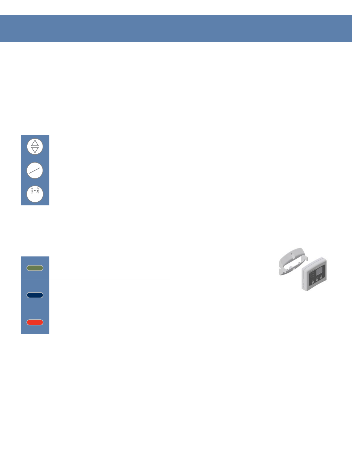
Selection Buttons
The VTMS is designed with three direct selection buttons:
Scroll: Allows user to scroll through current readings, average stats and device status information
displayed on the LCD Screen. Push and hold for 3 seconds to reset the device.
°C
°F
Users have the ability to manually reset the statistics within the device to zero without needing to use the MadgeTech 4
Software. Any data recorded up to that point is recorded and saved. To apply the manual reset, press and hold the scroll
key down for three seconds.
LED Indicators
Units: Allows users to change displayed units of measurement to either Celsius or Fahrenheit.
Wireless: Push and hold this button for 5 seconds to activate or deactivate wireless communication.
Mounting Instructions
Status: Green LED blinks every 5 seconds
to indicate the device is logging.
Wireless: Blue LED blinks every 15 seconds
to indicate the device is operating in
wireless mode.
Alarm: Red LED blinks every 1 second to
indicate an alarm condition is set.
The base securely snap to the
backside of the data logger for wall
mounting. There are two holes in
the base to allow for screws.
Find Quality Products Online at: sales@GlobalTestSupply.com
www.GlobalTestSupply.com
Product User Guide | 3
VTMS
SOFTWARE INSTALLATION
MadgeTech 4 Software
The MadgeTech 4 Software makes the process of downloading and reviewing data quick and easy,
and is free to download from the MadgeTech website.
MadgeTech 4 Software
1. Download the MadgeTech 4 Software on a Windows PC.
2. Locate and unzip the downloaded file (right click on the file and select Extract).
3. Open the MTInstaller.exe file.
4. Select a language, then follow the instructions provided in the MadgeTech 4 Setup Wizard to finish the MadgeTech 4
Software installation.
Installing the USB Interface Driver
USB Interface Drivers can easily be installed on a Windows PC, if they are not already
available and running.
1. Download the USB Interface Driver on a Windows PC by going to
2. Locate and unzip the downloaded file (right click on the file and select Extract).
3. Open the PreInstaller.exe file.
4. Select Install on the dialog box.
MadgeTech Cloud Services
MadgeTech Cloud Services allows users to remotely monitor
and manage groups of data loggers throughout a large facility or
multiple locations, from any internet enabled device. Transmit
real-time data to the MadgeTech Cloud Services platform via
the MadgeTech Data Logger Software running on a central PC or transmit directly to
the MadgeTech Cloud without a PC using the MadgeTech RFC1000 Cloud Relay (sold
separately). Sign up for a MadgeTech Cloud Services account.
For more detailed
information, download the
MadgeTech Software Manual
For more detailed
information, download the
MadgeTech Cloud Services
Find Quality Products Online at: sales@GlobalTestSupply.com
www.GlobalTestSupply.com
Product User Guide | 4
VTMS
ACTIVATING & DEPLOYING THE DATA LOGGER
1. Connect the RFC1000 wireless transceiver (sold separately)
to the Windows PC with the provided USB cable.
2. Additional RFC1000’s can be used as repeaters to
transmit over greater distances. If transmitting over
a distance greater than 500 feet indoors, 2,000 feet
outdoors or there are walls, obstacles or corners that
need to be maneuvered around, set up additional
RFC1000’s as needed. Plug each one into an electrical
outlet in the desired locations.
3. Verify that the data loggers are in wireless transmission
mode. Push and hold the Wireless button on the data
logger for 5 seconds to activate or deactivate wireless
communication.
CHANNEL PROGRAMMING
4. On the Windows PC, launch the MadgeTech 4 Software.
5. All active data loggers will be listed in the Device tab
within the Connected Devices panel.
6. To claim a data logger, select the desired data logger in
the list and click the Claim icon.
7. Once the data logger has been claimed, select a start
method in the Device tab.
For steps to claim the data logger and view data
using MadgeTech Cloud Services, refer to the
MadgeTech Cloud Services Software Manual at
Different wireless channels may be used to create multiple networks in one area, or to avoid wireless interference from
other devices. Any MadgeTech data logger or RFC1000 wireless transceiver that is on the same network is required to use
the same channel. If all of the devices are not on the same channel, the devices will not communicate with one another.
MadgeTech wireless data loggers and RFC1000 wireless transceivers are programmed by default on channel 25.
Changing the channel settings of the VTMS
1. Switch the wireless mode to OFF by holding down the
Wireless button on the data logger for 5 seconds.
2. Using the provided USB cable, plug the data logger into
the PC.
3. Open the MadgeTech 4 Software. Locate and select the
data logger in the Connected Devices panel.
4. In the Device tab, click the Properties icon.
5. Under the Wireless tab, select a desired channel
(11 - 25) that will match with the RFC1000.
6. Click Apply to save the settings to the device.
7. Disconnect the data logger.
8. Return the device to wireless mode by holding down
the Wireless button for 5 seconds.
CHANNEL NOTE: MadgeTech wireless data loggers and
wireless transceivers purchased prior to April 15, 2016
are programmed by default to channel 11. Please refer to
the Product User Guide provided with these devices for
instructions to change the channel selection if needed.
To configuring the channel settings of the
RFC1000 wireless transceiver (sold separately),
please refer to the RFC1000 Product User
Guide that shipped with the product or
download it from the MadgeTech website at
Find Quality Products Online at: sales@GlobalTestSupply.com
www.GlobalTestSupply.com
Product User Guide | 5

VTMS
PRODUCT MAINTENANCE
Battery
Replacement
Materials: U9VL-J Battery or any 9 V Battery
1. On the bottom of the data logger, open the battery
compartment by pulling in on the cover tab.
2. Remove the battery by pulling it from the
compartment.
3. Install the new battery, taking note of the polarity.
4. Push the cover closed until it clicks.
Recalibration
Recalibration is recommended annually for any data
logger; a reminder is automatically displayed in the
software when the device is due. To send devices back for
Find Quality Products Online at: sales@GlobalTestSupply.com
www.GlobalTestSupply.com
Product User Guide | 6
VTMS
TROUBLESHOOTING
Why is the wireless data logger not appearing in the software?
If the VTMS doesn’t appear in the Connected Devices panel, or an error message is received while using the VTMS,
try the following:
• Check that the RFC1000 is properly connected. For more information, see Troubleshooting wireless transceiver
problems (below).
• Ensure that the battery is not discharged. For best voltage accuracy, use a voltage meter connected to the battery of the
device. If possible, try switching the battery with a new 9V lithium.
• Ensure that the MadgeTech 4 Software is being used, and that no other MadgeTech Software (such as MadgeTech 2,
or MadgeNET) is open and running in the background. MadgeTech 2 and MadgeNET are not the compatible with the
VTMS.
• Ensure that the Connected Devices panel is large enough to display devices. This can be verified by positioning the
cursor on the edge of the Connected Devices panel until the resize cursor appears, then dragging the edge of the panel
to resize it.
• Ensure that the data logger and RFC1000 are on the same wireless channel. If the devices are not on the same channel,
the devices will not communicate with one another. Please refer to the Channel Programming section for information
on changing the device channel.
Troubleshooting wireless transceiver problems
Check that the software properly recognizes the connected RFC1000 wireless transceiver.
If the wireless data logger is not appearing in the Connected Devices list, it may be that the RFC1000 is not
properly connected.
1. In the MadgeTech 4 Software, click the File button, then click Options.
2. In the Options window, click Communications.
3. The Detected Interfaces box will list all of the available communication interfaces. If the RFC1000 is listed
here, this indicates it is recognized by the software.
Check that Windows recognizes the connected RFC1000 wireless transceiver.
If the software does not recognize the RFC1000, there may be a problem with Windows or the USB drivers.
1. In Windows, click Start, right-click Computer and choose Properties.
2. Select Device Manager in the left hand column.
3. Double-click on Universal Serial Bus Controllers.
4. Look for an entry for Data Logger Interface.
5. If the entry is present, and there are no warning messages or icons, then windows has correctly recognized
the connected RFC1000.
6. If the entry is not present, or has an exclamation point icon next to it, the USB drivers may need to be
installed. USB drivers can be downloaded from the MadgeTech website.
Ensure that the USB end of the RFC1000 is securely connected to the computer.
1. If the cable is connected to the PC, unplug it and wait ten seconds.
2. Reconnect the cable to the PC.
3. Check to make sure that the red LED is lit, indicating a successful connection.
Find Quality Products Online at: sales@GlobalTestSupply.com
www.GlobalTestSupply.com
Product User Guide | 7

VTMS
COMPLIANCE INFORMATION
This device complies with Part 15 of the FCC Rules. Operation is subject to the following two conditions: (1) this device may
not cause harmful interference, and (2) this device must accept any interference received, including interference that may
cause undesired operation.
To satisfy FCC RF Exposure requirements for mobile and base station transmission devices, a separation distance of 20 cm
or more should be maintained between the antenna of this device and persons during operation. To ensure compliance,
operation at closer than this distance is not recommended. The antenna(s) used for this transmitter must not be colocated or operating in conjunction with any other antenna or transmitter.
This device complies with Industry Canada license-exempt RSS standard(s). Operation is subject to the following two
conditions: (1) this device may not cause interference, and (2) this device must accept any interference, including
interference that may cause undesired operation of the device.
Le présent appareil est conforme aux CNR d’Industrie Canada applicables aux appareils radio exempts de licence.
L’exploitation est autorisée aux deux conditions suivantes: (1) l’appareil ne doit pas produire de brouillage, et (2)
l’utilisateur de l’appareil doit accepter tout brouillage radioélectrique subi, même si le brouillage est susceptible d’en
compromettre le fonctionnement.
Under Industry Canada regulations, this radio transmitter may only operate using an antenna of a type and maximum
(or lesser) gain approved for the transmitter by Industry Canada.
To reduce potential radio interference to other users, the antenna type and its gain should be so chosen that the
equivalent isotropically radiated power (e.i.r.p.) is not more than that necessary for successful communication.
Conformément à la réglementation d’Industrie Canada, le présent émetteur radio peut fonctionner avec une antenne
d’un type et d’un gain maximal (ou inférieur) approuvé pour l’émetteur par Industrie Canada. Dans le but de réduire les
risques de brouillage radioélectrique à l’intention des autres utilisateurs, il faut choisir le type d’antenne et son gain de
sorte que la puissance isotrope rayonnée équivalente (p.i.r.e.) ne dépasse pas l’intensité nécessaire à l’établissement d’une
communication satisfaisante.
Find Quality Products Online at: sales@GlobalTestSupply.com
www.GlobalTestSupply.com
Product User Guide | 8

VTMS
NEED HELP?
Product Support & Troubleshooting:
• Refer to the Troubleshooting section of this document.
• Visit our Knowledge Base online.
• Contact our friendly Customer Support Team.
MadgeTech 4 Software Support:
• Refer to the built-in help section of the MadgeTech 4 Software.
• Download the MadgeTech 4 Software Manual.
• Contact our friendly Customer Support Team.
MadgeTech Cloud Services Support:
• Download the MadgeTech Cloud Services Software Manual.
• Contact our friendly Customer Support Team.
Find Quality Products Online at: sales@GlobalTestSupply.com
www.GlobalTestSupply.com
DOC-1285036-00 | REV 10 2020.12.10
 Loading...