

Page 1
Red 485
Dark Blue Pantone 289
Light Blue 58% of Pantone 289
Red 485
Dark Blue Pantone 289
Light Blue 58% of Pantone 289
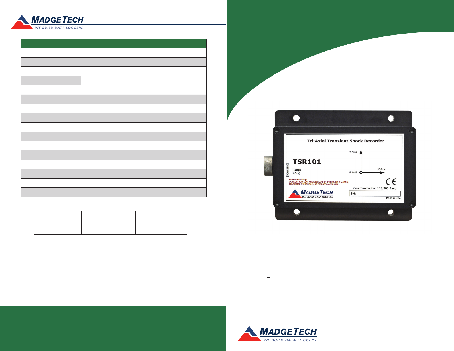
Description TSR101
Acceleration Sensor Shock (3 axes)
Accelerometer Type MEMS Semiconductor
Acceleration Range
*See Table for DetailsAcceleration Resolution
Calibrated Accuracy
Memory 349,471/channel
Reading Rate 1,024Hz to 1 second
Frequency Response 0Hz to approximately 400Hz (50, 100 g)
Typical Battery Life 7 days
Required Interface Package IFC200
Baud Rate 115,200
Operating Environment –20 °C to +60 °C, 0 to 95%RH (non-condensing)
Dimensions 3.5” x 4.4” x 1.0” (89 mm x 112 mm x 26 mm)
Materials Anodized aluminum
Weight 12 oz (340 g)
Approvals CE
Product Information Card
TSR101
*TSR101 Acceleration Range, Resolution and Accuracy
Range (g)
Resolution (g)
Accuracy (g)
+5 +50 +100 +250
0.01 0.05 0.1 0.2
+0.2 +1 +2 +4
Battery Warning
WARNING: FIRE, EXPLOSION, AND SEVERE BURN HAZARD. DO NOT SHORT CIRCUIT, CHARGE,
FORCE OVER DISCHARGE, DISASSEMBLE, CRUSH, PENETRATE OR INCINERATE. BATTERY MAY
LEAK OR EXPLODE IF HEATED ABOVE 60 °C (140 °F).
See MadgeTech’s terms and conditions at www.madgetech.com
Specifications subject to change.
MadgeTech, Inc.
6 Warner Road
Phone 603.456.2011
www.madgetech.com
l
Warner, NH 03278
l
Fax 603.456.2012
l
info@madgetech.com
DOC-1161035-00 REV 11 01.23.2018
TSR101-5
Tri-Axial +5g, Transient Shock Data Logger
TSR101-50
Tri-Axial +50g, Transient Shock Data Logger
TSR101-100
Tri-Axial +100g, Transient Shock Data Logger
TSR101-250
Tri-Axial +250g, Transient Shock Data Logger
To view the full MadgeTech product line,
visit our website at www.madgetech.com.
Page 2
TSR101
Product Information Card
Product Notes
How it Works
Once the logger is started samples are taken on each axis (X, Y and Z) every 1024Hz
(1 ms). These samples are compared with the trigger values and if it crosses the threshold
value then it records the timestamp and starts logging the triggered data.
If the samples are not above the threshold value then it is logged as the pre-trigger data.
Since only 50 pre-trigger values can be recorded the data gets overwritten if the logger is
not triggered within 50 pre-trigger values.
The sampling frequency is the same for all reading rates therefore the samples are skipped
based on the reading rate. For example: if the reading rate is 512Hz the samples are taken
every 1ms but every other sample gets logged instead of logging every sample.
Trigger Settings
Below is a table of default trigger values based on the range of the logger. All axis are
enabled to check for triggers at these g levels.
Range
Trigger Value
To edit trigger values, select Start Device from the Start Menu. Click Yes, then select
Trigger Settings. Click the Change button. Each axis can be set to trigger at a certain g
force level. Check the Enable Trigger box to enable the trigger for that axis. The values
can be typed in manually or configured by using the slider control. Click Save to save the
changes.
To initiate the TSR101 to constantly sample, set the high and low trigger settings to 0 g.
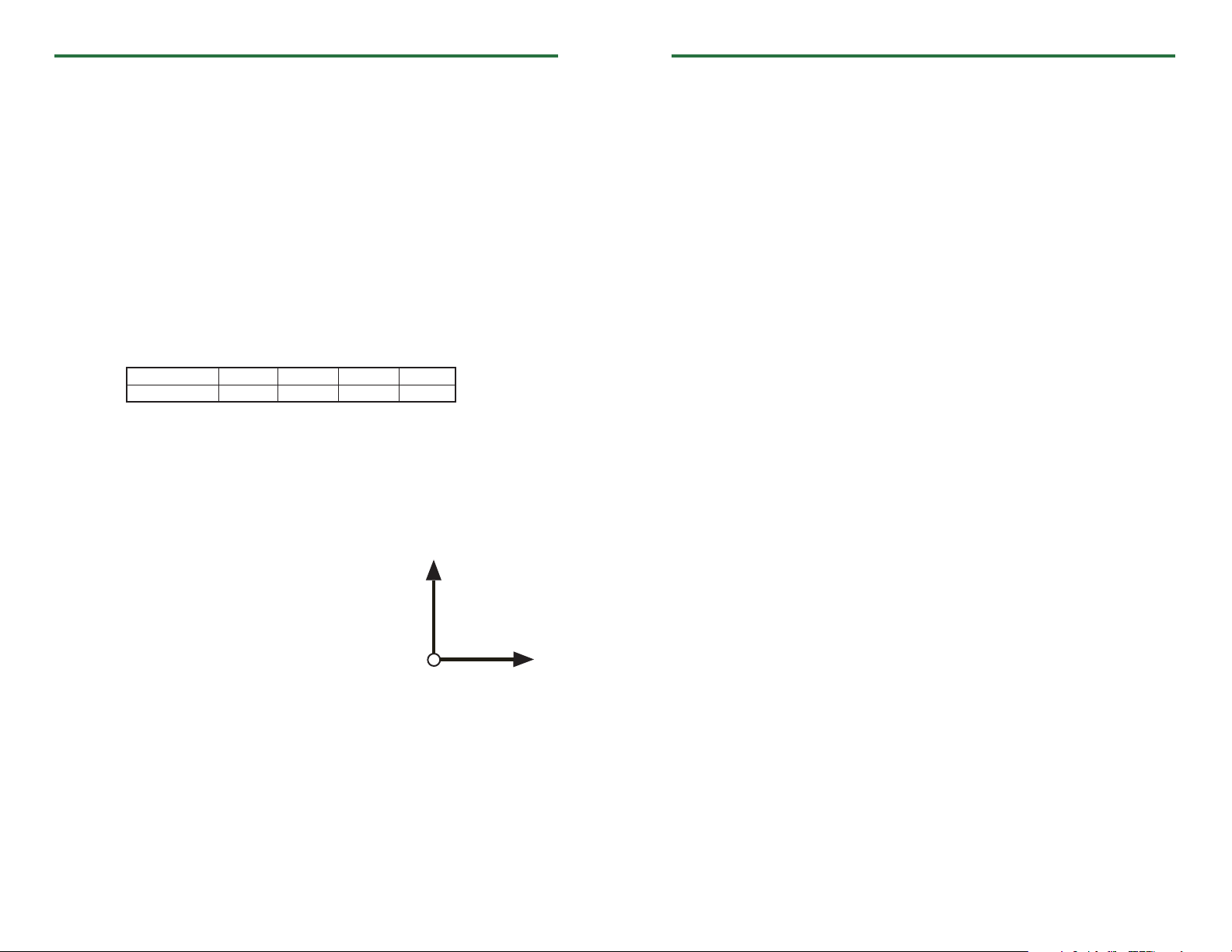
Axis Orientation
When the TSR101 is laying flat, with the label facing
up, the x-axis indicates left to right direction and will
read ~0 g when still. The y-axis reads in a top to bottom
direction and reads ~0 g when still. The z-axis reads
perpendicular to the other two axis, and will read ~1 g
when still.
5 g 50 g 100 g 250 g
2.5 g 25 g 52.5 g 120 g
Y-Axis
Z-Axis
X-Axis
Installation Guide
Installing the Interface cable
- IFC200
Insert the device into a USB port. The drivers will install automatically.
Installing the software
Insert the Software USB Stick in an open USB port. If the autorun does not appear, locate
the drive on the computer and double click on Autorun.exe. Follow the instructions
provided in the Wizard.
Device Operation
Connecting and Starting the data logger
- Once the software is installed and running, plug the interface cable into the data logger.
- Connect the USB end of the interface cable into an open USB port on the computer.
- The device will appear in the Connected Devices list, highlight the desired data logger.
- For most applications, select “Custom Start” from the menu bar and choose the desired
start method, reading rate and other parameters appropriate for the data logging
application and click “Start”. (“Quick Start” applies the most recent custom start options,
“Batch Start” is used for managing multiple loggers at once, “Real Time Start” stores the
dataset as it records while connected to the logger.)
- The status of the device will change to “Running”, “Waiting to Start” or “Waiting to
Manual Start”, depending upon your start method.
- Disconnect the data logger from the interface cable and place it in the environment to
measure.
Note: The device will stop recording data when the end of memory is reached or the device is stopped. At this point the device
cannot be restarted until it has been re-armed by the computer.
Downloading data from a data logger
- Highlight the data logger in the Connected Devices list. Click “Stop” on the menu bar.
- Once the data logger is stopped, with the logger highlighted, click “Download”. You will
be prompted to name your report.
- Downloading will offload and save all the recorded data to the PC.
Device Maintenance
Battery Replacement
Materials:
3/32” HEX Driver (Allen Key)
Replacement Battery (U9VL-J)
- Remove the cover from the device by unscrewing the four screws.
- Remove the battery from its compartment and unsnap it from the connector.
- Snap the new battery into the terminals and verify it is secure.
- Replace the cover taking care not to pinch the wires. Screw the enclosure back together
securely.
Note: Be sure not to over tighten the screws or strip the threads.
Recalibration
The TSR101 standard calibration is performed at 0 g for the X-axis, 0 g for the Y-axis and
1 g for the Z-axis.
To send the devices back, visit www.madgetech.com, select Services then RMA Process.
 Loading...