

Page 1
Red 485
Dark Blue Pantone 289
Light Blue 58% of Pantone 289
Red 485
Dark Blue Pantone 289
Light Blue 58% of Pantone 289
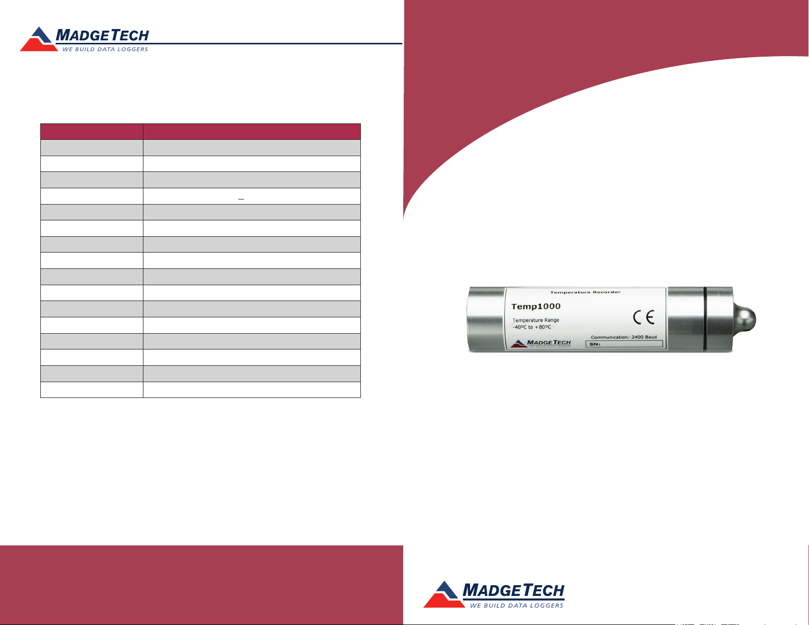
Description Temp1000
Temperature Sensor Internal semiconductor
Temperature Range –40 °C to +80 °C
Temperature Resolution 0.1 °C
Calibrated Accuracy +0.5 °C
Memory 32,767
Sample Rate 2 seconds up to 12 hours
Required Interface Package IFC110 or IFC200
Baud Rate 2,400
Typical Battery Life 1 year
Operating Environment -40 °C to +80 °C, 0 to 100 %RH
Material Available in anodized aluminum or 303 stainless steel
Dimensions 4.3 in x 1.0 in dia. (110mm x 26mm dia.)
Weight (Aluminum) 4 oz (110 g)
Weight (Stainless) 8 oz (230 g)
Approvals CE
Submergible Fully Submergible (IP68)
Product Information Card
Temp1000
Temp1000
Rugged Temperature Data Logger with Aluminum Enclosure
Temp1000-SS
Rugged Temperature Data Logger with Stainless Steel Enclosure
Battery Warning
WARNING: FIRE, EXPLOSION, AND SEVERE BURN HAZARD. DO NOT SHORT CIRCUIT, CHARGE,
FORCE OVER DISCHARGE, DISASSEMBLE, CRUSH, PENETRATE OR INCINERATE. BATTERY MAY
LEAK OR EXPLODE IF HEATED ABOVE 80 °C (176 °F).
See MadgeTech’s terms and conditions at www.madgetech.com
Specifications subject to change.
MadgeTech, Inc.
6 Warner Road
Phone 603.456.2011
www.madgetech.com
l
Warner, NH 03278
l
Fax 603.456.2012
l
info@madgetech.com
DOC-1012035-00 REV 10 2014.04.24
To view the full MadgeTech product line,
visit our website at www.madgetech.com.
Page 2

Temp1000
Product Notes
Getting Started
To access the COM Port for the interface cable, unscrew the key-ring end cap. Screw the
end cap onto the data logger until the o-ring cannot be seen, before deploying it.
Submergibility
The Temp1000 is fully submergible and is rated IP68. It can be placed in environments
with up to 150 feet (45 m) of water.
O-Rings
O-ring maintenance is a key factor when properly caring for the Temp1000. The o-rings
ensure a tight seal and prevent liquid from entering the inside of the device.
Please refer to the application note “O-Rings 101: Protecting Your Data”, found on the
MadgeTech website, for information on how to prevent O-ring failure.
Installation Guide
Installing the Interface cable
- IFC200
Insert the device into a USB port. The drivers will install automatically.
- IFC110
Plug the serial cable into the port and verify it is secure.
Installing the software
Insert the Software USB Stick in an open USB port. If the autorun does not appear, locate
the drive on the computer and double click on Autorun.exe. Follow the instructions
provided in the Wizard.
Device Operation
Connecting and Starting the data logger
- Once the software is installed and running, plug the interface cable into the data logger.
- Connect the USB end of the interface cable into an open USB port on the computer.
- The device will appear in the Connected Devices list, highlight the desired data logger.
- For most applications, select “Custom Start” from the menu bar and choose the desired
start method, reading rate and other parameters appropriate for the data logging
application and click “Start”. (“Quick Start” applies the most recent custom start options,
“Batch Start” is used for managing multiple loggers at once, “Real Time Start” stores the
dataset as it records while connected to the logger.)
- The status of the device will change to “Running”, “Waiting to Start” or “Waiting to
Manual Start”, depending upon your start method.
- Disconnect the data logger from the interface cable and place it in the environment to
measure.
Note: The device will stop recording data when the end of memory is reached or the device is stopped. At this point the
device cannot be restarted until it has been re-armed by the computer.
Product Information Card
Downloading data from a data logger
- Highlight the data logger in the Connected Devices list. Click “Stop” on the menu bar.
- Once the data logger is stopped, with the logger highlighted, click “Download”. You will
be prompted to name your report.
- Downloading will offload and save all the recorded data to the PC.
Device Maintenance
Battery Replacement
Materials:
Small Needle Nose Pliers
Replacement Battery (TLH-5902)
- Carefully unscrew the communications end cap.
- Using a small pair of needle nose pliers, remove the snap-ring by carefully pinching the
gold retaining ring together.
- Press gently on the white disk to force one end up and pull the electronics out.
- The battery is the purple cylinder on the circuit board. Gently remove the old battery.
- Insert the new battery one lead at a time, using pliers to fully push the leads into the
sockets. Note: The battery should be flat against the circuit board, and the positive lead
should be closest to the communications jack.
- Ensure the circuit board is inserted into the white plastic bushing. The sensor cable
should not be twisted, or kinked. From the connection to the circuit board, it should run
up towards the battery, then down to the sensor.
- Insert the electronics back into the tube, gently push the board back into the tube and
push the white disk back around the communication jack. and screw the cap back on.
Recalibration
The Temp1000 standard calibration is one point at 25 °C.
Pricing:
Recalibration traceable to NIST $70.00
Recalibration $40.00
Additional Services:
Verification Point $15.00 per point
Prices and specifications subject to change. See MadgeTech’s terms and conditions at www.madgetech.com.
To send the devices back, visit www.madgetech.com, select Services then RMA Process.
 Loading...