

Page 1

Red 485
Dark Blue Pantone 289
Light Blue 58% of Pantone 289
Red 485
Dark Blue Pantone 289
Light Blue 58% of Pantone 289
Description SVR101
Acceleration Sensor MEMS semiconductor
Acceleration Range +50 g
Acceleration Resolution 0.05 g
Calibrated Accuracy +1 g
Sample Rate 256Hz (decimated to 128Hz)
FFT Range
FFT Window Period 2 seconds
FFT Sampling Period 2 seconds to 4 hrs
Memory 16Mbit (3,971 samples)
Sample Rate 2 seconds up to 4 hours
Required Interface Package IFC200
Baud Rate 115,200
Typical Battery Life 60 hours (9V lithium)
Operating Environment –20 °C to +60 °C, 0 to 95%RH
Material Anodized aluminum
Dimensions 3.5” x 4.4” x 1.0” (89 mm x 112 mm x 26 mm)
Weight 12 oz (340 g)
Approvals CE
(signicant math errors occur at 0-1.5Hz)
0 to 128Hz in 1Hz bins
Product User Guide
SVR101
IMPORTANT: The SVR101 data logger requires MadgeTech 2 Data Logger
Software and is NOT compatible with MadgeTech 4 Data Logger Software.
Battery Warning
WARNING: FIRE, EXPLOSION, AND SEVERE BURN HAZARD. DO NOT SHORT CIRCUIT, CHARGE,
FORCE OVER DISCHARGE, DISASSEMBLE, CRUSH, PENETRATE OR INCINERATE. BATTERY MAY
LEAK OR EXPLODE IF HEATED ABOVE 60 °C (140 °F).
See MadgeTech’s terms and conditions at www.madgetech.com
Specifications subject to change.
MadgeTech, Inc.
6 Warner Road
Phone 603.456.2011
www.madgetech.com
l
Warner, NH 03278
l
Fax 603.456.2012
l
info@madgetech.com
DOC-1108035-00 REV 12 2015.05.15
SVR101
Spectral Vibration and Recorder
To view the full MadgeTech product line,
visit our website at www.madgetech.com.
Page 2
SVR101
Product User Guide
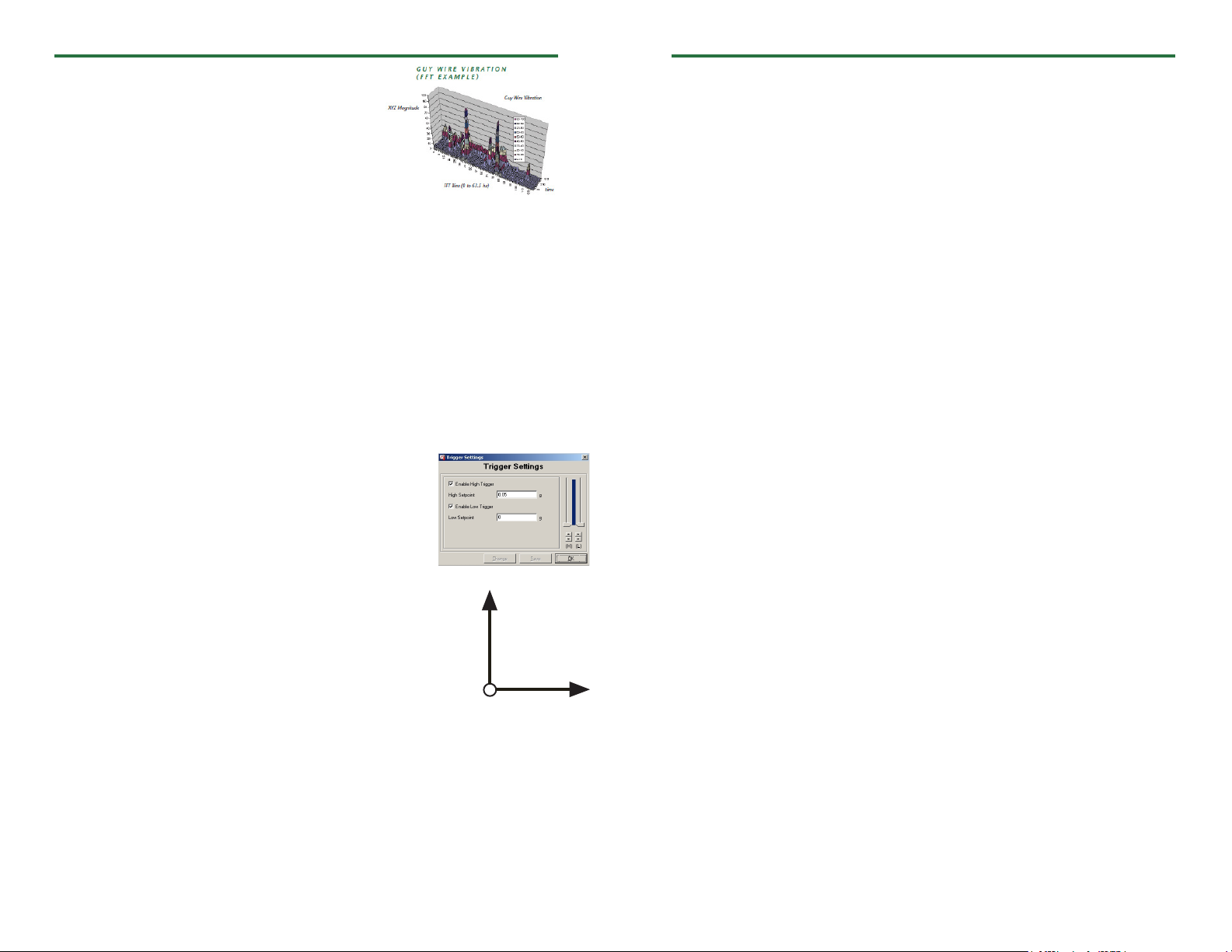
Product Notes
The SVR101 monitors frequencies from 0Hz to 63.5Hz,
up to a magnitude of 50 g’s. Using a Fast Fourier
Transform (FFT), the data output is presented in a
3-dimensional graph, when copied to Excel®. The
result is a spectrum of magnitudes broken down into
frequency bins of “energy” over time.
The SVR101 utilizes trigger settings when monitoring
vibration. Once a trigger setting is exceeded, the SVR101 samples at 128Hz and every 2
seconds, a “window”, places the samples into bins. The “bins” are categorized into 0.5Hz
intervals.
The selected reading rate defines how many 2 second bin samples will be averaged. With
a faster reading rate, more noise is shown in the FFT. By using a slower reading rate, the
noise is averaged out.
If the frequency being monitored is occurring less than once per second, the SVR101
would not sense the vibration. Math errors occur doing the computing of 0-1.0Hz bins,
therefore in the SVR101 the first 3 bins (0, 0.5, 1.0), represent 0Hz.
Once the data is downloaded to the software, use the Copy Data to Excel® function to
view the 3-D graph.
Trigger Settings
To edit trigger values, when the device is connected, click the
Device Menu, then Start Device. Click Yes , then select the
Trigger Settings box. Click the Change button. The trigger
values can be typed in manually, or changed by using the slide
control. An individual high or low trigger may be enabled, or
both. Click Save to save the changes.
Axis Orientation
When the Shock101 is laying flat with the label facing up, the
x-axis reads left to right on a horizontal plane, and will read ~0 g’s
when still. The y-axis reads top to bottom on a horizontal plane and
will read ~0 g’s when still. The z-axis reads perpendicular to the other
two axis’s, and will read around ~1 g’s_ when still.
Y-Axis
Z-Axis
Installation Guide
Installing the Interface cable
- IFC200:
Insert the device into a USB port. The drivers will install automatically.
Installing the software
Software can also be downloaded from the MadgeTech website at the following link: www.
madgetech.com/software-download. Double click the zipped download file and follow the
steps to finsh downloading
X-Axis
- After a moment, a box will appear stating a device has been found.
- Click OK. The Device Status box will appear. Click OK.
- At this point, communications have been configured for your logger. These settings can
be found under the Communication Menu.
Note: For additional installation instructions refer to your “Data Logger & Software Operating Manual”.
Device Operation
Starting the data logger
- Click Device Menu then Start Device.
- Choose the desired start method.
- Choose the start parameters by selecting a Reading Rate suitable for your application.
- Enter in any other desired parameters and click Start.
- A box will appear stating the data logger has been started. Click OK.
- Disconnect the data logger from the interface cable and place it in the environment to
measure.
Note: The device will stop recording data when the end of memory is reached or the device is stopped. At this point the
device cannot be restarted until it has been re-armed by the computer.
Downloading data from a data logger
- Connect the data logger to the interface cable.
- Click the Device Menu then Read Device Data. This will offload all recorded data onto
the PC.
Device Maintenance
Battery Replacement
Materials:
3/32” HEX Driver (Allen Key)
Replacement Battery (U9VL-J)
- Remove the cover from the device by unscrewing the four screws.
- Remove the battery from its compartment and unsnap it from the connector.
- Snap the new battery into the terminals and verify it is secure.
- Replace the cover taking care not to pinch the wires. Screw the enclosure back together
securely.
Note: Be sure not to over tighten the screws or strip the threads.
Recalibration
The SVR101 standard calibration is performed at 0 g on the x-axis, 0 g on the y-axis, and
1 g on the z-axis.
Prices and specifications subject to change. See MadgeTech’s terms and conditions at www.madgetech.com
To send the devices back, visit www.madgetech.com, select Services then RMA Process.
Connecting the data logger
- Once the software is installed and running, plug the interface cable into the data logger.
- Click the Communication Menu, then Auto Configure Port.
 Loading...