

Page 1
Red 485
Dark Blue Pantone 289
Light Blue 58% of Pantone 289
Red 485
Dark Blue Pantone 289
Light Blue 58% of Pantone 289
Product Quick Reference Card
Device Maintenance
Battery Replacement
Materials:
Small Phillips Head Screwdriver
Replacement Battery (U9VL-J)
- Puncture the center of the back label with the screw driver
and unscrew the enclosure.
- Remove the battery by pulling it perpendicular to the circuit
board.
- Insert the new battery into the terminals and verify it is secure.
- Screw the enclosure back together securely.
Note: Be sure not to over tighten the screws or strip the threads.
Battery Warning
WARNING: FIRE, EXPLOSION, AND SEVERE BURN HAZARD. DO NOT
SHORT CIRCUIT, CHARGE, FORCE OVER DISCHARGE, DISASSEMBLE,
CRUSH, PENETRATE OR INCINERATE. BATTERY MAY LEAK OR
EXPLODE IF HEATED ABOVE 60°C (140°F).
Recalibration
The RFpHTemp101A standard calibration is performed at 50
Ohms and 150 Ohms for the RTD channel and 0mV and 250mV
for the pH channel.
Note: MadgeTech does not offer calibration of pH inputs in
combination with a pH electrode or probe.
Pricing:
Recalibration traceable to NIST $90.00
Recalibration $70.00
Additional:
As Found Data $15.00 per parameter/channel
Verification Point $15.00 per point
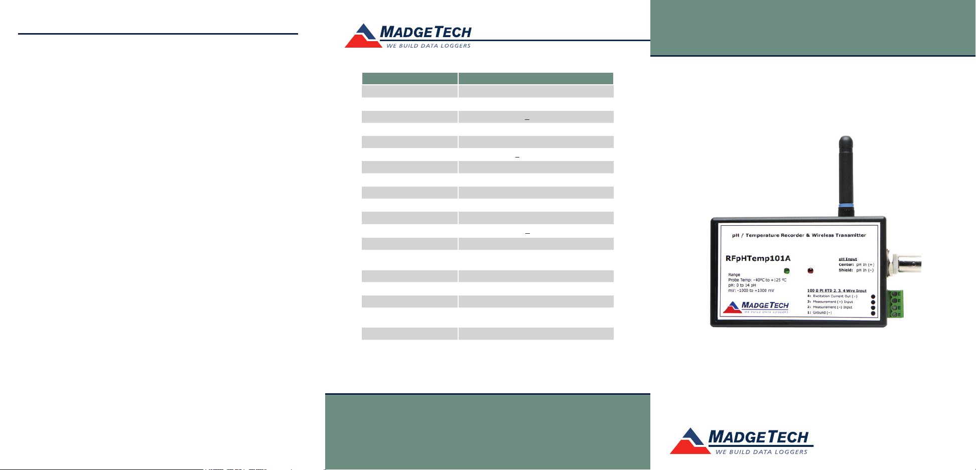
Part Number RFpHTemp101A
pH Measurement Range 0 to 14pH
pH Measurement Resolution 0.01 pH
pH Measurement Accuracy +0.1 pH
RTD Measurement Range -0 to +100°C
RTD Measurement Resolution 0.01°C
RTD Measurement Accuracy +0.1°C @ 25°C
Memory 13,107/channel
Sample Rate 30 seconds up to 12 hours
LED Red & Greem
Required Interface Package RFC101A
PC Baud Rate 57,600
RF Carrier Frequency 418 + 0.075MHz
RF Baud Rate 4,800
RF Range Typical Outdoors/Line of Sight: Up to 120’ (36m)
Typical Battery Life 1 Year
Material ABS Plastic
Operating Environment -5 to +50°C, 0 to 95%RH (Non-Condensing)
Dimensions 4.5” x 2.4” x 1.0” plus 2.0” Antenna
Approvals US (FCC), CA (IC)
Typical Indoors/Urban: Up to 40’ (12m)
(114mm x 61mm x 26mm plus 51mm Antenna)
Specifications subject to change.
See MadgeTech’s terms and conditions at www.madgetech.com
Product Information Card
RFpHTemp101A
RFpHTemp101A
Precision RTD Temperature Recorder and Wireless Transmitter
To send the devices back, visit www.madgetech.com, select
Services then RMA Process.
MadgeTech, Inc.
PO Box 50
Phone 603.456.2011
www.madgetech.com
l
Warner, NH 03278
l
Fax 603.456.2012
l
info@madgetech.com
To view the full MadgeTech product line,
visit our website at www.madgetech.com.
REV D 2009.06.11
Page 2
RFpHTemp101A
3-Red
4-Red or Short to 3
1-Black or Short to 2
2-Black
Connector for 100
Ohm PtRTD
IFC101 connector
BNC connector for
pH electrode
Product Notes
LEDs
Once started, the green LED will blink at the specified reading
rate. The red LED will blink each time a reading is sent to the
receiver. The LED on the RFC101A receiver will blink when a
reading is received.
Alarm Settings
The wireless series does have alarm features. Refer to the
“Operations Manual for RF Series Data Loggers” located on the
software CD for a full list of instructions.
Using the pHTEMP10
1. The pH electrode should have a BNC output connection, or an
appropriate adapter. Select a probe with an output impedance
less than 300 megaohms at the desired temperature. The
OMEGA PHE-4200 Series of probes satisfy this condition
above 0 ºC (32 ºF), and have a BNC output connection.
2. The temperature probe must be a 100 ohm platinum RTD, in
the standard 2-,3- or 4-wire configuration. The pHTEMP101
is designed to achieve exceptional accuracy with the 4-wire
probe, but will still yield measurements better than required
for a pH-measurement with the 2- or 3-wire probes.
3. Insure that the probe you select can be connected to the
Phtemp101 RTD input by selecting a probe with lead wires,
or by attaching an adapter that will allow you to connect
wire leads to the probe. OMEGA’s PR-10 and PR-11 series
of probes have the proper leads for direct connection to the
Phtemp101.
4. Connect the probes to the data logger.
5. Refer to the description of your pH probe
for a calibration procedure.
KEY
4- Excitation Current Out (+)
3-Measurement (+) Input
2- Measurement(-) Input
1- Ground (-)
Installation Guide
Installing the Interface cable
- IFC200, IFC202 or IFC300
Refer to the “Quick Start Guide” included in the package.
- IFC110, IFC102 or IFC103
Plug the serial cable into the port and verify it is secure.
- USB-1 or USB-101
Install the USB drivers from the CD provided in the kit, than
plug the USB cable into the computer and the serial cable into
the serial port.
Installing the software
Insert the Software CD in the CD-ROM Drive. If the autorun
does not appear, locate the drive on the computer and double
click on Autorun.exe. Follow the instructions provided in the
Wizard.
Connecting the data logger
- Once the software is installed and running, plug the interface
cable into the data logger.
- Click the Communication Menu, then Auto Configure Port.
- After a moment, a box similar to the following will appear;
- Click OK. The Device Status box will appear. Click OK.
- At this point, communications have been configured for your
logger. These settings can be found under the Communication
Menu.
Note: For additional installation instructions refer to your “Data
Logger & Software Operating Manual”.
Product Quick Reference Card
Device Operation
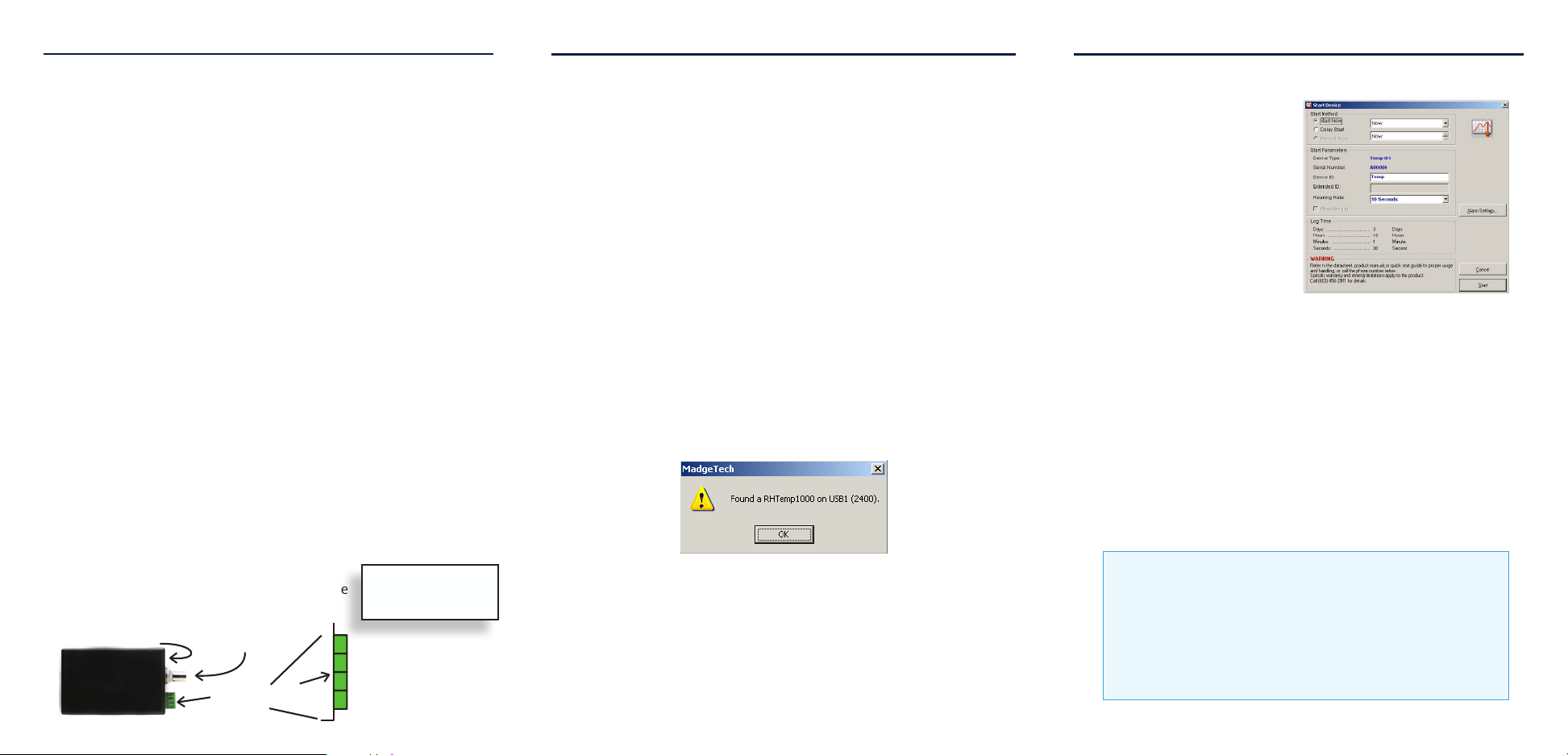
Starting the data logger
- Click Device Menu then
Start Device.
- Choose the desired start
method.
- Choose the start parameters
by selecting a Reading Rate
suitable for your application.
- Enter in any other desired
parameters and click Start.
- A box will appear stating the
data logger has been started.
Click OK.
- Disconnect the data logger from the interface cable and
place it in the environment to measure.
- Plug in the RFC101A receiver. Disconnectinf the IFC110 is
necessary.
- Click the Communication Menu, Select Baud Rate. Select 4800
baud. This is the baud rate for the receiver.
- Data will now transmit back to the PC from the data logger.
Note: The device will stop recording data when the end of memory
is reached or the device is stopped. At this point the device cannot
be restarted until it has been re-armed by the computer.
Downloading data from a data logger
- Connect the data logger to the interface cable.
- Click the Device Menu then Read Device Data. This will
offload all recorded data onto the PC.
Technical Support
Visit www.madgetech.com, or call (603) 456-2011.
Technical support is also available by e-mailing
support@madgetech.com
Additional product information is available by e-mailing
info@madgetech.com.
 Loading...