

Page 1
Product User Guide
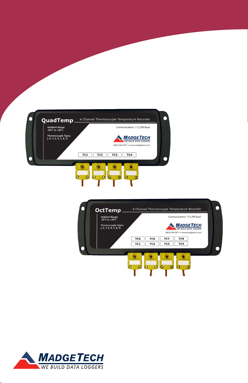
QuadTemp and OctTemp
QuadTemp
4-Channel Thermocouple Based Temperature Data Logger
OctTemp
8-Channel Thermocouple Based Temperature Data Logger
To view the full MadgeTech product line,
visit our website at www.madgetech.com.
Page 2

Product User Guide
Table of Contents
QuadTemp and OctTemp Data Loggers
Quick Start Steps ........................................... 1
Product Overview .......................................... 2
Additional Features & Operation ................. 3-4
Product Maintenance ..................................... 5
Recalibration .................................................. 5
RMA Instructions ............................................. 5
General Specifications .................................. 6-9
Support ...................................... Back Cover
To view the full MadgeTech product line,
visit our website at www.madgetech.com.
Page 3

QuadTemp and OctTemp
Quick Start Steps
Product Operation
1. Insert the Software USB Stick in an open USB port. If the autorun does not appear,
locate the drive on the computer and double click on Autorun.exe. Follow the instructions
provided in the Wizard. Install the MadgeTech 4 Software and USB Drivers onto a
Windows PC.
2. Launch the MadgeTech 4 Software.
3. The IFC200 interface comes with a USB cable. Plug one end of the cable into an avail-
able USB port on the PC and plug the opposite end of the cable into the communication
port on the IFC200. The drivers will install automatically.
4. The device will appear in the Connected Devices list, highlight the desired data logger.
For most applications, select “Custom Start” from the menu bar and choose the desired
start method, reading rate and other parameters appropriate for the data logging application and click “Start”. (“Quick Start” applies the most recent custom start options, “Batch
Start” is used for managing multiple loggers at once, “Real Time Start” stores the dataset as
it records while connected to the logger.) The status of the device will change to “Running”,
“Waiting to Start” or “Waiting to Manual Start”, depending upon your start method.
5. Disconnect the data logger from the interface cable and place it in the environment to
measure. Note: The device will stop recording data when the end of memory is reached or
the device is stopped. At this point the device cannot be restarted until it has been
re-armed by the computer.
6. To download data, connect the logger to the interface cable. Highlight the data log-
ger in the Connected Devices list. Click “Stop” on the menu bar. Once the data logger is
stopped, with the logger highlighted, click “Download”. You will be prompted to name
your report. Downloading will offload and save all the recorded data to the PC.
1
Page 4
Product User Guide
Product Overview
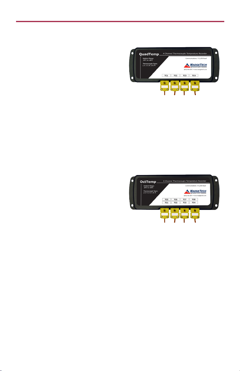
The QuadTemp is a four channel thermocouple
temperature data logger with a reading rate
of up to 4 Hz. It can measure and record data
for up to 500,000 readings per channel. To
maximize memory capacity, users can disable
unused channels to add additional memory
onto enabled channels. For easy identification,
each channel can be named with up to a ten
digit title. In addition, the QuadTemp features individual cold junction compensation for
each channel providing increased accuracy and response time, and if a probe is removed or
severed during logging, the software automatically annotates the data.
The QuadTemp is ideal for a variety of applications, whether it is remote temperature
monitoring, or multiple points in a central location. Data from all channels is simultaneously
logged. After the monitoring cycle is complete, data can be downloaded for analysis. The
QuadTemp comes with a wall mounted 120 VAC/9 VDC power adapter.
Note: European customers should choose the QuadTemp-EU model under the ordering information. This model includes a wall
mounted 230VAC@50Hz/9VDC power adapter.
The OctTemp is an eight channel thermocouple
data logger with a reading rate of up to 4 Hz. It
can measure and record data for up to 500,000
readings per channel. To maximize memory
capacity, users can disable unused channels to
add additional memory onto enabled channels.
For easy identification, each channel can be
named with up to a ten digit title. In addition,
the OctTemp features individual cold junction compensation for each channel providing
increased accuracy and response time, and if a probe is removed or severed during logging,
the software automatically annotates the data.
The OctTemp is ideal for a variety of applications, whether it is remote temperature
monitoring, or multiple points in a central location. The OctTemp comes with a wall mounted 120 VAC/9 VDC power adapter.
Note: European customers should choose the OctTemp-EU model under the ordering information. This model includes a wall
mounted 230 VAC@50 Hz/9 VDC power adapter.
2
Page 5

QuadTemp and OctTemp
Additional Features and Operation
Wiring the Data Logger
Wiring Options
The QuadTemp has four SMP connections and the
OctTemp has eight. These connections allow the user
to insert subminiature thermocouple plugs into the
connectors on the device. The diagram below shows
how to connect the individual thermocouples for each of the devices.
Warning: Note the polarity instructions. Do not attach wires to the wrong terminals.
Manual Start
Click the Custom Start button on the Device panel, or right-click on the device and hover
on the start selection, then chose custom start. Apply the options desired and select Start.
Once armed through the software, to activate the Manual Start, hold the recessed push
button, adjacent to the interface cable plug, down for 10 seconds. The green LED will begin
to blink rapidly for 10 seconds, which signifies the push-button start has been activated. The
green LED will continue to blink every 5 seconds. To see the change in the status, hit Refresh
Devices within the software.
Enable/Disable Channels
By default, all channels are enabled.
1. In the Connected Devices panel, click the device desired.
2. On the Device Tab, in the Information Group, click Properties. Or, right-click the device
and select Properties in the context menu.
3. Toggle the Enable Data Recording options for the thermocouple channels as desired.
4. Apply these changes, there will be a prompt to reset the device, select yes.
Note: When the checkmark is empty, the channel is disabled and will not record data or appear in the downloaded datasets.
When the checkmark is clearly checked, it will be visible and record data.
Thermocouple Type
To change the thermocouple type
1. In the Connected Devices panel, click the device desired.
2. On the Device Tab, in the Information Group, click Properties. Or, right-click the device
and select Properties in the context menu.
3. On the General Tab, change the Thermocouple type in the drop down menu.
4. Apply these changes, there will be a prompt to reset the device, select yes.
Please note that the same thermocouple type must be used on all of the channels.
LEDs
Once started, the green LED will flash at 5 second intervals to indicate that the device is running.
3
Page 6

Product User Guide
Additional Features and Operation Continued
Set Password
To password protect the device so that others cannot start, stop or reset the device;
1. In the Connected Devices panel, click the device desired.
2. On the Device Tab, in the Information Group, click Properties. Or, right-click the device
and select Properties in the context menu.
3. On the General Tab, click Set Password.
4. Enter and confirm the password in the box that appears, then select OK.
Channel Naming
Up to a 10-character channel name can be programmed into the data logger for each
channel. This ability helps to rename a channel in a report to distinguish it from other
similarly named channels.
1. In the Connected Devices panel, click the device desired.
2. On the Device Tab, in the Information Group, click Properties. Or, right-click the device
and select Properties in the context menu.
3. In the Channels panel, find the channel desired, then select “Use custom name.”
4. This will prompt a space to type in a name.
5. Select OK, then there will be a prompt to reset the device, select yes.
Still need help? For more troubleshooting tips and information, refer to the built in help
section of the MadgeTech 4 software, visit our Knowledge Base online at
www.madgetech.com/kbase or contact us for customer support at 603-456-2011.
4
Page 7

QuadTemp and OctTemp
Product Maintenance
Battery Replacement
Materials: 3/32” HEX Driver (Allen Key) and Replacement Battery (U9VL-J)
- Remove the cover from the device by unscrewing the two screws.
- Remove the battery from its compartment and unsnap it from the connector.
- Snap the new battery into the terminals and verify it is secure.
- Replace the cover taking care not to pinch the wires. Screw the enclosure back together
securely. Note: Be sure not to over tighten the screws or strip the threads.
Recalibration
The QuadTemp or OctTemp standard calibration is one point at 25 °C for the internal
temperature sensor and 0 mVs for the thermocouple channels.
Pricing:
Recalibration traceable to NIST $70.00
Recalibration $40.00
Additional Services:
Verification Point $15.00 per point
Channel (1st) $30.00 at 25 °C
$45.00 at custom point
Additional Channels $3.00 at 25 °C
$4.50 at custom point
Prices and specifications subject to change. See MadgeTech’s terms and conditions at www.madgetech.com To send the
devices back, visit www.madgetech.com, select Services then RMA Process.
RMA Instructions
To send a device back in to MadgeTech, follow the instructions below to create an RMA
(Return Merchandise Authorization) on the MadgeTech website:
1. Visit www.madgetech.com, under the Services tab select RMA Process.
2. When the web page opens, please sign in. If this is the first time, select Click here to
register an account and create one. Once signed in, click on the Make New RMA
button and fill in all the blank fields.
3. Complete the applicable fields on the form including customer Billing and Shipping
information, even if they are the same. Please see the field explanation below for a more
detailed description about questions asked in the Device Information section.
4. When all of the fields are complete, click Generate RMA.
5. Print out the confirmation page that follows containing the RMA number and
MadgeTech’s address for shipping. A Return Merchandise Authorization must be
accompanied by a copy of the RMA paperwork and shipping is prepaid by the
customer. The RMA number should be clearly marked on the outside of the package.
6. Please ship the package via UPS, FedEx, TNT, or DHL to the address listed on the
confirmation page. USPS will not ship MadgeTech data loggers.
7. A notification email will be automatically sent when MadgeTech has received the RMA.
5
Page 8

Product User Guide
QuadTemp General Specifications
4 Internal Channels
Temperature Range -20 ºC to +60 ºC
Temperature Resolution 0.05 ºC
Calibrated Accuracy ±0.5 ºC (0 to +50 ºC)
4 Remote Channels
Remote Channel
Thermocouple Types
Thermocouple Connection Female subminiature (SMP)
Cold Junction Compensation Automatic, based on internal channel
Maximum Thermocouple
Resistance
Thermocouple Range (ºC) Resolution Accuracy
Start Modes
Real Time Recording
Memory
Reading Rate 4 readings per second up to 1 every 24 hours
J, K, T, E, R, S, B, N
1000 Ω, <100 Ω recommended
J -210 to +760 0.1 ºC ±0.5 ºC
K -270 to +1370 0.1 ºC ±0.5 ºC
T -270 to +400 0.1 ºC ±0.5 ºC
E -270 to +980 0.1 ºC ±0.5 ºC
R -50 to +1760 0.5 ºC ±2.0 º C
S -50 to +1760 0.5 ºC ±2.0 º C
B +50 to +1820 0.5 ºC ±2.0 º C
N -270 to +1300 0.1 ºC ±0.5 ºC
Software programmable immediate start or delay start up
to six months in advance
May be used with PC to monitor and record data in real
time
500,000 readings per channel, channels can be disabled
to increase memory
Calibration Digital calibration through software
Calibration Date Automatically recorded within device
Battery Type
9 Volt lithium or alkaline battery included,
user replaceable
6
Page 9

QuadTemp and OctTemp
QuadTemp General Specifications Cont.
Battery Life 18 months typical
Data Format Date and time stamped ºC, ºF, K, ºR, mV, V
Time Accuracy ±1 minute/month
Computer Interface USB (Interface cable required); 115,200 baud
Software XP SP3/Vista/Windows 7/Windows 8 (MadgeTech 4 only)
Operating Environment -20 ºC to +60 ºC, 0 %RH to 95 %RH non-condensing
Dimensions 7.24 in x 2.7 in x 1.02 in (183 mm x 68 mm x 26 mm)
Material Black anodized aluminum
Weight 15.2 oz (430 g)
Approvals CE
Battery Warning
BATTERY WARNING: FIRE, EXPLOSION, AND SEVERE BURN HAZARD. DO NOT SHORT CIRCUIT, CHARGE, FORCE
OVER DISCHARGE, CRUSH, PENETRATE, OR INCINERATE. BATTERY MAY LEAK OR EXPLODE IF HEATED ABOVE
80 ºC (176 ºF).
Specifications subject to change.
See MadgeTech’s terms and conditions at www.madgetech.com
7
Page 10

Product User Guide
OctTemp General Specifications
8 Internal Channels
Temperature Range -20 ºC to +60 ºC
Temperature Resolution 0.05 ºC
Calibrated Accuracy ±0.5 ºC (0 to +50 ºC)
8 Remote Channels
Remote Channel
Thermocouple Types
Thermocouple Connection Female subminiature (SMP)
Cold Junction Compensation Automatic, based on internal channel
Maximum Thermocouple
Resistance
Thermocouple Range (ºC) Resolution Accuracy
Start Modes
Real Time Recording
Memory
Reading Rate 4 readings per second up to 1 every 24 hours
J, K, T, E, R, S, B, N
1000Ω, <100Ω recommended
J -210 to +760 0.1 ºC ±0.5 ºC
K -270 to +1370 0.1 ºC ±0.5 ºC
T -270 to +400 0.1 ºC ±0.5 ºC
E -270 to +980 0.1 ºC ±0.5 ºC
R -50 to +1760 0.5 ºC ±2.0 º C
S -50 to +1760 0.5 ºC ±2.0 º C
B +50 to +1820 0.5 ºC ±2.0 º C
N -270 to +1300 0.1 ºC ±0.5 ºC
Software programmable immediate start or delay start up
to six months in advance
May be used with PC to monitor and record data in real
time
500,000 readings per channel, channels can be disabled
to increase memory
Calibration Digital calibration through software
Calibration Date Automatically recorded within device
Battery Type
9 Volt lithium or alkaline battery included,
user replaceable
8
Page 11

QuadTemp and OctTemp
OctTemp General Specifications Cont.
Battery Life 18 months typical
Data Format Date and time stamped ºC, ºF, K, ºR, mV, V
Time Accuracy ±1 minute/month
Computer Interface USB (Interface cable required); 115,200 baud
Software XP SP3/Vista/Windows 7/Windows 8 (MadgeTech 4 only)
Operating Environment -20 ºC to +60 ºC, 0 %RH to 95%RH non-condensing
Dimensions 7.24 in x 2.7 in x 1.26 in (183 mm x 68 mm x 32 mm)
Material Black anodized aluminum
Weight 17.3 oz (490g)
Approvals CE
Battery Warning
BATTERY WARNING: FIRE, EXPLOSION, AND SEVERE BURN HAZARD. DO NOT SHORT CIRCUIT, CHARGE, FORCE
OVER DISCHARGE, CRUSH, PENETRATE, OR INCINERATE. BATTERY MAY LEAK OR EXPLODE IF HEATED ABOVE
80 ºC (176 ºF).
Specifications subject to change.
See MadgeTech’s terms and conditions at www.madgetech.com
9
Page 12

Troubleshooting Tips
Why is the data logger not appearing in the software?
If the QuadTemp or OctTemp doesn’t appear in the Connected Devices panel, or an error message
is received while using either device, try the following:
• Check that the IFC200 is properly connected. For more information, see Troubleshooting Interface
Cable problems (below).
• Ensure that the battery is not discharged. For best voltage accuracy, use a voltage meter connected to
the battery of the device. If possible, try switching the battery with a new 9V lithium.
• Ensure that no other MadgeTech software (such as MadgeTech 2) is running in the background.
• Ensure that the Connected Devices panel is large enough to display devices. This can be verified by
positioning the cursor on the edge of the Connected Devices panel until the resize cursor appears, then
dragging the edge of the panel to resize it. The screen layout may also be reset in the options menu by
selecting File, Options, and scrolling to the bottom.
Troubleshooting Interface Cable problems
Check that the software properly recognizes the connected IFC200 interface cable.
If either data logger is not appearing in the Connected Devices list, it may be that the IFC200 is not
properly connected.
1. In the software, click the File button, then click Options.
2. In the Options window, click Communications.
3. The Detected Interfaces box will list all of the available communication interfaces. If the IFC200 is
listed here, then the software has correctly recognized and is ready to use it.
Check that Windows recognizes the connected IFC200 interface cable.
If the software does not recognize the IFC200, there may be a problem with Windows or the USB drivers.
1. In Windows, click Start, right-click Computer and choose Properties or press Windows+Break as a
keyboard shortcut.
2. Click Device Manager in the left hand column.
3. Double click Universal Serial Bus Controllers.
4. Look for an entry for Data logger Interface.
5. If the entry is present, and there are no warning messages or icons, then windows has correctly
recognized the connected IFC200.
6. If the entry is not present, or has an exclamation point icon next to it, the USB drivers may need to
be installed. These are available on the software flash drive included with the IFC200, and on the
MadgeTech website.
Ensure that the USB end of the IFC200 is securely connected to the computer.
1. Locate the USB-A plug of the IFC200.
2. If the interface cable is connected to the PC, unplug it. Wait ten seconds.
3. Reconnect the cable to the PC.
4. Check to make sure that the red LED is lit, indicating a successful connection.
MadgeTech, Inc.
6 Warner Road
Phone 603.456.2011
www.madgetech.com
l
Warner, NH 03278
l
Fax 603.456.2012
l
info@madgetech.com
DOC-1002/1003036-00 REV 3 2014.08.05
 Loading...