

Page 1
Product User Guide
QuadTCTemp2000V2 and
OctTCTemp2000V2
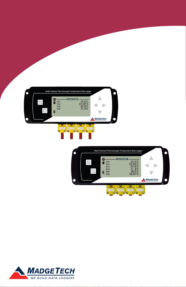
QuadTCTemp2000V2
4-Channel Thermocouple Based Temperature Data Logger with LCD Display
OctTCTemp2000V2
8-Channel Thermocouple Based Temperature Data Logger with LCD Display
*Thermocouple Plugs/Probes Sold Separately
To view the full MadgeTech product line,
visit our website at madgetech.com.
Page 2

QuadTCTemp2000V2 and OctTCTemp2000V2
Table of Contents
Quick Start Steps ........................................................ 3
Product Overview .................................................... 4-5
Computer Interface ...................................................... 6
Software Installation ................................................... 7
Activating & Deploying the Data Logger ...................... 6
Device Functions ....................................................... 7-8
Device Operation .......................................................... 9
Device Maintenance ............................................... 9-10
General Specifications ................................................ 11
To view the full MadgeTech product line, visit our website at www.madgetech.com.
2
Page 3

Product User Guide
Quick Start Steps
1. Install the MadgeTech 4 Software (version 4.2.12.0 or later) and USB Drivers onto a
Windows PC (Windows XP SP3 or later).
2. Wiring the data logger with the desired thermocouple probes.
3. Connect the data logger to the Windows PC with the IFC200 (sold separately).
4. Launch the MadgeTech 4 Software. The QuadTCTemp2000V2 / OctTCTemp2000V2 will
appear in the Connected Devices window indicating the device has been recognized.
5. Programming thermocouple type within the MadgeTech 4 Software.
6. Select the start method, reading rate and any other parameters appropriate for the
desired data logging application. Once configured, deploy the data logger by clicking
the Start icon.
7. To download data, select the device in the list, click the Stop icon, and then click the
Download icon. A graph will automatically display the data.
3
Page 4
QuadTCTemp2000V2 and OctTCTemp2000V2
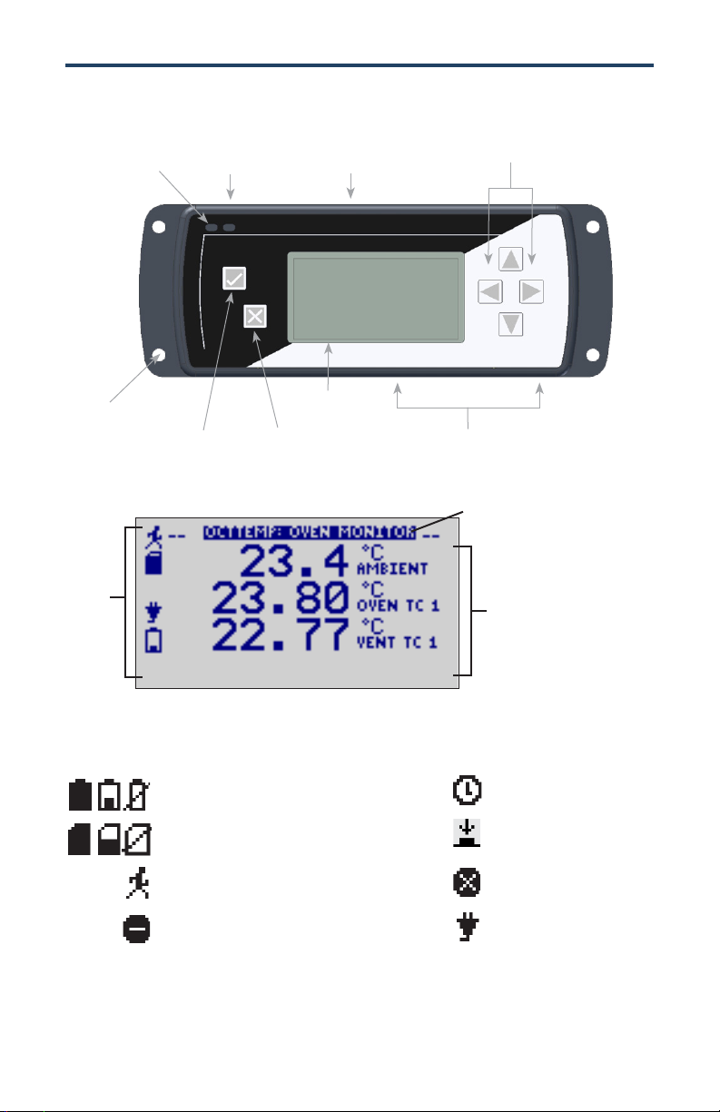
Display Overview
Directional
Status LEDs
9-12VDC
Input
Communications
Port
Key Pad
Mounting
Holes
OK Key
LCD Screen Overview
Status
Indicators
Status Indicators
Battery Power (Full, Half-full, Empty)
Memory Remaining (Empty, Half-full, Full)
Device is running
Device is stopped
Cancel Key
LCD
Channel Inputs
Screen
Title
Screen
Content
Delay Start
Push-button (Manual) Start
Device reset has occurred
External power present
4
Page 5

Product User Guide
LED Function
Green LED: Blinks to indicate that the device is armed and/or running. Blinks when
confirming or scrolling through keypad options.
Red LED: Blinks to indicate low battery or low memory.
Blue LED on Thermocouple channels: Blinks at the reading rate (but no more than once
every other second).
Wiring the Data Logger
Wiring Diagrams
The SMP connections allow the user to insert subminiature thermocouple plugs into
the connectors on the device. The diagram below shows how to connect the individual
thermocouples for each of the devices.
Warning: Note the polarity instructions. Do not attach wires to the wrong terminals.
Thermocouple Channel Numbers
TC5 TC6 TC7 TC8
TC1 TC2 TC3 TC4
Programming Thermocouple Type
To change the thermocouple type in the MadgeTech software:
1. In the Connected Devices panel, click the device desired.
2. On the Device Tab, in the Information Group, click Properties. Or, right-click the
device and select Properties in the context menu.
3. On the General Tab, change the Thermocouple type in the drop down menu.
4. Apply these changes, there will be a prompt to reset the device, select yes.
Please note that the same thermocouple type must be used on all of the channels.
5
Page 6

QuadTCTemp2000V2 and OctTCTemp2000V2
Computer Interface
Fully insert the male connector of the IFC200 interface cable into the female receptacle of
the data logger. Fully insert the female USB connector into the USB. (Please see the Data
Logger Software manual for further information.)
*WARNING: Install driver before connecting a device using a USB for the first time. See the
Software manual for further information.
Software Installation
Installing the MadgeTech 4 Software
The MadgeTech 4 Software makes the process of downloading and reviewing data quick
and easy, and is free to download from the MadgeTech website.
1. Download the MadgeTech 4 Software (version 4.2.12.0 or later) on a Windows PC
(Windows XP SP3 or later) by going to madgetech.com.
2. Locate and unzip the downloaded file (typically you can do this by right clicking on the
file and selecting Extract).
3. Open the MTInstaller.exe file.
4. You will be prompted to select a language, then follow the instructions provided in the
MadgeTech 4 Setup Wizard to finish the MadgeTech 4 Software installation.
6
Page 7

Device Functions
Channel Options
Each of the OctTCTemp2000V2’s channels have
several options that are configurable by the user through
the device’s display screen menus and th e software.
Show or Hide Channels on the Home Screen
The user may choose to either show or hide channels
on the home screen.
To change channel visibility from the Home Screen:
1. Press to view first channel screen
2. Use to view additional channels
3. On desired channel screen use to highlight Visible
4. Use to choose Show or Hide
5. Press to return to the Home Screen
—OR—
1. Use to highlight desired channel
2. Press to view channel screen
3. Use to highlight Visible
4. Use to choose Show or Hide
5. Press to return to the Home Screen
Product User Guide
Change Channel Display Size
Channels may be viewed in a number of different sizes. The smallest size allows for an overview
of several channels at once, while the largest gives at-a-glance access to one or two channels.
To change channel display size from the Home Screen:
1. Press to enter the Main Menu
2. Use to highlight Setup Menu
3. Press to enter the Setup Menu
4. Use to highlight Channel Size
5. Use to choose the desired channel size
6. Press once to return to the Main Menu
7. Press again to return to the Home Screen
7
Page 8

QuadTCTemp2000V2 and OctTCTemp2000V2
Change Channel Units
Channels can be customized to display readings in a variety of convenient units. Units available
for selection will vary according to channel type.
Note: Changing display units will not affect logged data.
To change channel display from the Home Screen:
1. Press to view first channel screen
2. Use to view additional channels
3. On desired channel screen use to highlight Units
4. Use to choose the desired unit option
5. Press to return to the Home Screen
—OR—
1. Use to highlight desired channel
2. Press to view channel screen
3. Use to highlight Units
4. Use to choose the desired unit option
5. Press to return to the Home Screen
Note: Hit X to update all channels.
8
Page 9

Product User Guide
Device Operation
Connecting and Starting the data logger
1. Once the software is installed and running, plug the interface cable into the data logger.
2. Connect the USB end of the interface cable into an open USB port on the computer.
3. The device will appear in the Connected Devices list, highlight the desired data logger.
4. For most applications, select “Custom Start” from the menu bar and choose the desired
start method, reading rate and other parameters appropriate for the data logging
application and click “Start”. (“Quick Start” applies the most recent custom start options,
“Batch Start” is used for managing multiple loggers at once, “Real Time Start” stores the
dataset as it records while connected to the logger.)
5. The status of the device will change to “Running”, “Waiting to Start” or “Waiting to
Manual Start”, depending upon your start method.
6. Disconnect the data logger from the interface cable and place it in the environment to
measure.
Note: The device will stop recording data when the end of memory is reached or the device is stopped. At this point the
device cannot be restarted until it has been re-armed by the computer.
Downloading data from a data logger
1. Connect the logger to the interface cable.
2. Highlight the data logger in the Connected Devices list. Click “Stop” on the menu bar.
3. Once the data logger is stopped, with the logger highlighted, click “Download”. You
will be prompted to name your report.
4. Downloading will offload and save all the recorded data to the PC.
Device Maintenance
Recalibration
Recalibration is recommended annually.
Additional:
Custom calibration and verification point options available, please call for pricing.
Call for custom calibration options to accommodate specific application needs.
Prices and specifications subject to change. See MadgeTech’s terms and conditions at madgetech.com.
To send devices to MadgeTech for calibration, service or repair, please use the MadgeTech RMA Process by visiting
madgetech.com, then under the services tab, select RMA Process.
9
Page 10

QuadTCTemp2000V2 and OctTCTemp2000V2
Battery Information
BATTERY WARNING
This data logger contains a lithium battery. Do not cut the battery open,
incinerate, or recharge. Do not heat lithium batteries above the specified operating
temperature.* Dispose of the battery in accordance with local regulations.
*See the individual specification sheets at madgetech.com.
Battery Replacement
This product does not have any user-serviceable parts except the battery which should be
replaced periodically. The battery life is affected by battery type, ambient temperature,
sample rate, sensor selection, off-loads and LCD usage. The device has a battery status indicator on the LCD. If the battery indication is low, or if the device seems to be inoperable, it
is recommended that the battery be replaced.
Materials: 3/32” HEX Driver (Allen Key) and a Replacement Battery (U9VL-J)
- Remove the back cover from the device by unscrewing the two screws.
- Remove the battery from its compartment and unsnap it from the connector.
- Snap the new battery into the terminals and verify it is secure.
- Replace the cover taking care not to pinch the wires. Screw the enclosure back together.
Note: Be sure not to over tighten the screws or strip the threads.
10
Page 11

General Specifications
Part Number QuadTCTemp2000V2 OctTCTemp2000V2
Product User Guide
Internal Channel
Temperature Sensor
Internal Channel
Temperature Resolution
Internal Channel Accuracy ±0.5 °C (0 °C to 50 °C)
Remote Channel Temperature
Sensor Range, Resolution & Accuracy
Cold Jct. Compensation Automatic
Channels 4 internal & 4 remote 8 internal & 8 remote
Memory (all channels enabled) 261,888 Readings per channel 130,944 Readings per Channel
Reading Rate 4 Hz up to 24 hours
Required Interface Package IFC200
Baud Rate 115,200
Typical Battery Life
Operating Environment
Material Anodized aluminum
Dimensions
Approvals CE
* Remote Channel Range, Resolution & Accuracy
18 month battery life with display off. 3 months typical with
0 %RH to 95 %RH (non–condensing)
7.24 in x 2.7 in x 1.14 in
(183 mm x 68 mm x 29 mm)
Semiconductor
0.01 °C (0.018 °F)
*See Table for Details
continuous display use.
-20 °C to +60 °C (-4 °F to +140 °F),
7.24 in x 2.7 in x 1.39 in
(183 mm x 68 mm x 36 mm)
Thermocouple Range (°C) Resolution Accuracy
J -210 to +760 0.1 °C +0.5 °C
K -270 to +1370 0.1 °C +0.5 °C
T -270 to +400 0.1 °C +0.5 °C
E -270 to +980 0.1 °C +0.5 °C
R -50 to +1760 0.5 °C +2.0 °C
S -50 to +1760 0.5 °C +2.0 °C
B +50 to +1820 0.5 °C +2.0 °C
N -270 to +1300 0.1 °C +0.5 °C
Specifications subject to change.
See MadgeTech’s terms and conditions at madgetech.com
11
Page 12

MadgeTech, Inc.
6 Warner Road
Phone (603) 456.2011
madgetech.com
l
Warner, NH 03278
l
info@madgetech.com
l
Fax (603) 456.2012
DOC-1364035-00 REV 1 2019.05.29
 Loading...