

Page 1

Red 485
Dark Blue Pantone 289
Light Blue 58% of Pantone 289
Red 485
Dark Blue Pantone 289
Light Blue 58% of Pantone 289
Description QuadProcess OctProcess
Current Range
Current Resolution
Calibrated Accuracy
Input Impedance
Channels 4 8
Memory 32,767/channel 16,383/channel
Reading Rate 1 reading every second up to 1 reading every 12 hours
LED Indicator None
Required Interface Package IFC200
Baud Rate 2,400
Typical Battery Life 1 year
Operating Environment -20 °C to +60 °C, 0 %RH to 95 %RH (non–condensing)
Material Anodized aluminum
Dimensions
Weight 13 oz (370 g) 17 oz (480 g)
Approvals -
3.5 in x 4.4 in x 1.0 in
(89 mm x 112 mm x 26
mm)
*See Table Below
3.5 in x 4.4 in x 1.5 in
(89 mm x 112 mm x 39
mm)
Product User Guide
OctProcess and QuadProcess
*Current Series Range, Resolution and Calibrated Accuracy
Nominal Range +1 mA +25 mA +100 mA
Measurement Range
Common Mode Input Range 0 to 2.5 V 0 to 2.5 V 0 to 2.5 V
Resolution 0.05 µA 1 µA 5 µA
Calibrated Accuracy @ 25 °C 50 Ω 10 Ω 2 Ω
+1.5 mA +30 mA +120 mA
Battery Warning
WARNING: FIRE, EXPLOSION, AND SEVERE BURN HAZARD. DO NOT SHORT CIRCUIT, CHARGE,
FORCE OVER DISCHARGE, DISASSEMBLE, CRUSH, PENETRATE OR INCINERATE. BATTERY MAY
LEAK OR EXPLODE IF HEATED ABOVE 60 °C (140 °F).
DOC-1057035-00 REV 12 2014.11.25
Find Quality Products Online at: sales@GlobalTestSupply.com
www.GlobalTestSupply.com
OctProcess-1mA
8-Channel Low Level DC Current
Data Logger
OctProcess-25mA
8-Channel Low Level DC Current
Data Logger
OctProcess-100mA
8-Channel Low Level DC Current
Data Logger
QuadProcess-1mA
4-Channel Low Level DC Current
Data Logger
QuadProcess-25mA
4-Channel Low Level DC Current
Data Logger
QuadProcess-100mA
4-Channel Low Level DC Current
Data Logger
Page 2
QuadProcess and OctProcess
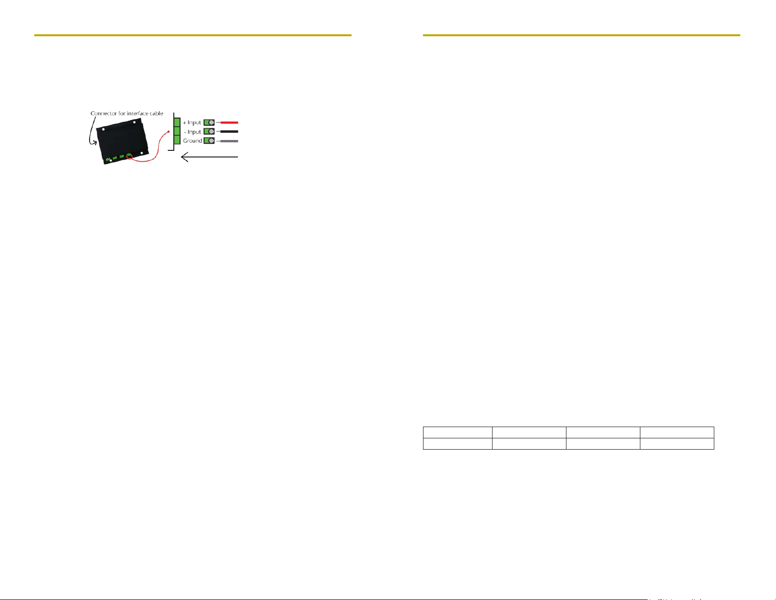
Wiring the Data Logger
Wiring Options
The QuadProcess and OctProcess both have two-position removable screw terminal
connections. The QuadProcess has 4 connections, the OctProcess has 8 connections. They
accept 3-wire configurations.
Warning: Note the polarity instructions. Do not attach wires to the wrong terminals.
Product Notes
Engineering Units
Engineering units are used to convert one measurement reading to another. The
MadgeTech software allows for software level Engineering Units (conversion applied to
data after download). Certain devices have device level Engineering Units, which upon
download automatically appear in the chosen unit of measure.
Please refer to the application note “Engineering Units”, found on the MadgeTech website,
for information on how to manage Engineering Units. Also view the Engineering Units
Video for step-by-step setup instructions.
Installation Guide
Installing the Interface cable
- IFC200
Insert the device into a USB port. The drivers will install automatically.
- IFC110
Plug the serial cable into the port and verify it is secure.
Installing the software
The Software can be downloaded from the MadgeTech website at the following link: www.
madgetech.com/software-download. Follow the instructions provided in the Installation
Wizard.
Device Operation
Connecting and Starting the data logger
- Once the software is installed and running, plug the interface cable into the data logger.
- Connect the USB end of the interface cable into an open USB port on the computer.
- The device will appear in the Connected Devices list, highlight the desired data logger.
- For most applications, select “Custom Start” from the menu bar and choose the desired
start method, reading rate and other parameters appropriate for the data logging
application and click “Start”. (“Quick Start” applies the most recent custom start options,
Product User Guide
“Batch Start” is used for managing multiple loggers at once, “Real Time Start” stores the
dataset as it records while connected to the logger.)
- The status of the device will change to “Running”, “Waiting to Start” or “Waiting to
Manual Start”, depending upon your start method.
- Disconnect the data logger from the interface cable and place it in the environment to
measure.
Note: The device will stop recording data when the end of memory is reached or the device is stopped. At this point the device
cannot be restarted until it has been re-armed by the computer.
Downloading data from a data logger
- Highlight the data logger in the Connected Devices list. Click “Stop” on the menu bar.
- Once the data logger is stopped, with the logger highlighted, click “Download”. You will
be prompted to name your report.
- Downloading will offload and save all the recorded data to the PC.
Device Maintenance
Battery Replacement
Materials:
- Remove the cover from the device by unscrewing the four screws.
- Remove the battery from its compartment and unsnap it from the connector.
- Snap the new battery into the terminals and verify it is secure.
- Replace the cover taking care not to pinch the wires. Screw the enclosure back together
securely. Note: Be sure not to over tighten the screws or strip the threads.
Recalibration
The QuadProcess or OctProcess standard calibration is at two points. The points are
dependent on the range of the data logger.
Additional Services:
Custom calibration and verification point options available, please call for pricing.
Calibration Points 0 mA and .9-1 mA 0 mA and 22.5-25 mA 0 mA and 90-100 mA
3/32” HEX Driver (Allen Key) and a Replacement Battery (U9VL-J)
Range 1 mA 25 mA 100 mA
Find Quality Products Online at: sales@GlobalTestSupply.com
www.GlobalTestSupply.com
 Loading...