

Page 1
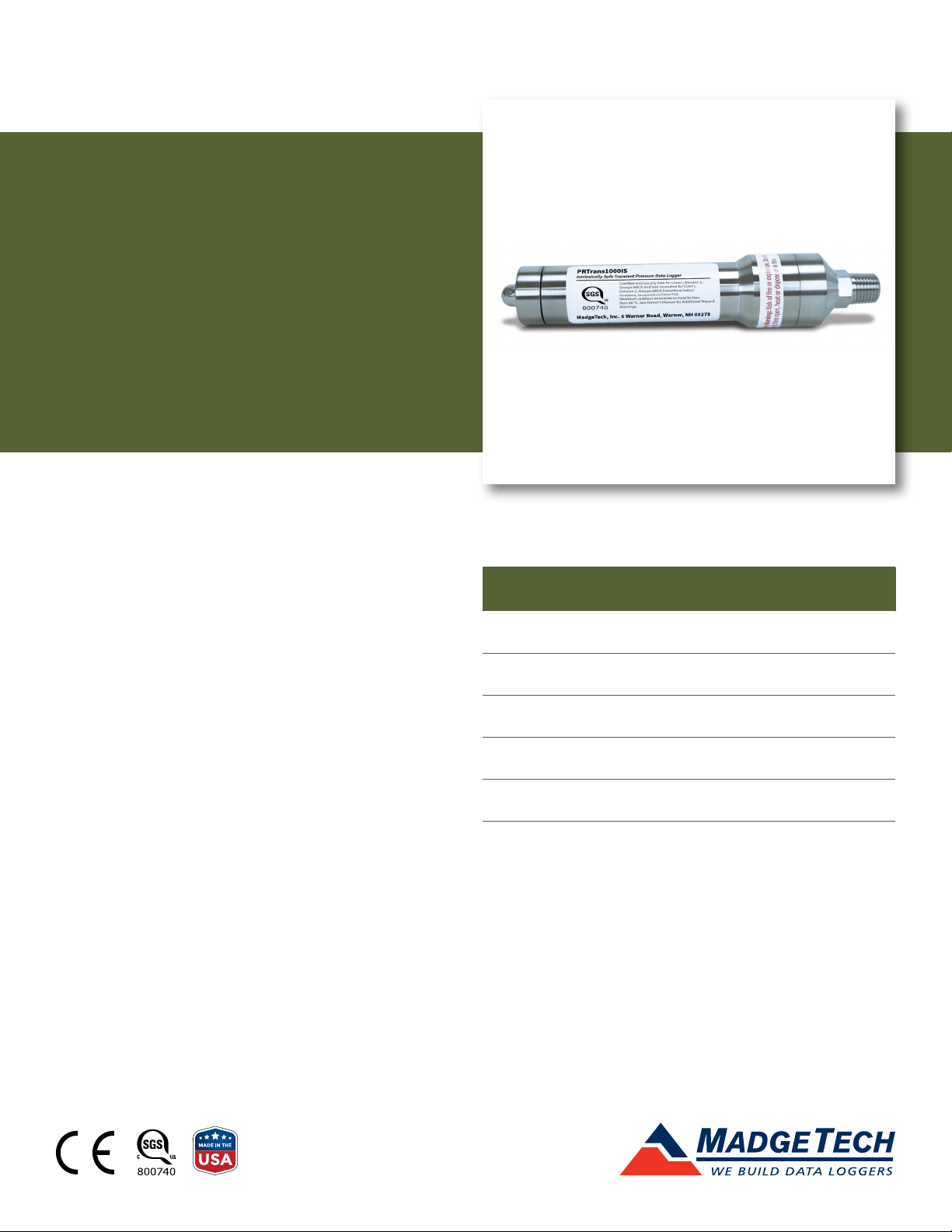
PRTrans1000IS
Intrinsically Safe Transient
Pressure Data Logger
PRODUCT
USER GUIDE
To view the full MadgeTech product line, visit
our website at madgetech.com.
TABLE OF CONTENTS
2 Product Overview
2 Installation Guide
3 Device Operation
4 Device Maintenance
4 Need Help?
Page 2

PRTrans1000IS
PRODUCT USER GUIDE
Product Overview
The PRTrans1000IS samples up to 100 Hz (10 ms) but
records data based on user-defined pressure thresholds.
The device can be set to start the trigger on high and/or
low thresholds and end the trigger after either a chosen
number of samples, or when the signal crosses over
the set stop threshold. The device can record up to 255
events and take as many as 262,143 pressure samples.
The PRTrans1000IS has been certified as intrinsically safe
certification in accordance with the latest issue of FM3600
and FM3610.
Certified Intrinsically Safe for:
• Class 1 Division 1 Group ABCD
• Class 1 Division 2 Group ABCD
• Temperature Class: T4A
Operational Warnings
• When used in hazardous locations, the PRTrans1000IS is
to be installed prior to the location becoming hazardous
and removed only after the area is no longer hazardous.
• The maximum allowed ambient temperature for the
PRTrans1000IS (under any circumstances) is 80 °C. The
minimum rated operating temperature is -40 °C.
• The PRTrans1000IS is approved for use only with the
Tadiran TL-2150/P battery. Replacement with any other
battery will void the safety rating.
• Batteries are user replaceable, but are to be removed or
replaced only in locations known to be non-hazardous.
• Tampering or replacement of non-factory components
may adversely affect the safe use of the product, and is
prohibited. Except for replacement of the battery, the
user may not service the PRTrans1000IS. MadgeTech,
Inc. or an authorized representative must perform all
other service to the product.
Installation Guide
Installing the Software
The Software can be downloaded from the MadgeTech
website at madgetech.com. Follow the instructions
provided in the Installation Wizard.
Installing the Interface Cable
To access the COM Port for the interface cable, unscrew the
key-ring end cap. Connect the device into a USB port with
the interface cable. The drivers will install automatically.
Screw the end cap back onto the data logger until the
O-ring cannot be seen, before deploying the data logger.
Pressure Sensor
To use the pressure sensor for gauge measurements,
screw the ¼ inch male NPT fitting into the pipe to be
measured with a ⁄ inch wrench.
Ordering Information
• 901271-00 — PRTrans1000IS-1000-PSIA
• 901275-00 — PRTrans1000IS-100-PSIA
• 901279-00 — PRTrans1000IS-100-PSIG
• 901283-00 — PRTrans1000IS-300-PSIA
• 901287-00 — PRTrans1000IS-300-PSIG
• 901291-00 — PRTrans1000IS-30-PSIA
• 901295-00 — PRTrans1000IS-30-PSIG
• 901299-00 — PRTrans1000IS-5000-PSIA
• 901303-00 — PRTrans1000IS-500-PSIA
• 901307-00 — PRTrans1000IS-500-PSIG
• 900298-00 — IFC200 USB Interface Cable
• 901744-00 — Tadiran TL-2150/P Replacement Battery
Product User Guide | 2
Page 3

PRTrans1000IS
PRODUCT USER GUIDE
Device Operation
Connecting and Starting the Data Logger
1. Once the software is installed and running, plug the
interface cable into the data logger (see Installing the
Interface Cable instructions).
2. Connect the USB end of the interface cable into an
open USB port on the computer.
3. The data logger will automatically appear under
Connected Devices within the software.
4. For most applications, select Custom Start from
the menu bar and choose the desired start method,
reading interval and other parameters appropriate for
the data logging application and click Start. (Quick
Start applies the most recent custom start options,
Batch Start is used for managing multiple loggers at
once, Real Time Start stores the dataset as it records
while connected to the logger.)
5. The status of the device will change to Running,
Waiting to Start or Waiting for Trigger, depending
upon your start method.
6. Disconnect the data logger from the interface cable
and place it in the environment to measure.
Note: The device will stop recording data when the end of memory
is reached or the device is stopped. At this point the device cannot be
restarted until it has been re-armed by the computer.
Downloading Data from a Data Logger
1. Connect the data logger to the interface cable.
2. Highlight the data logger in the Connected Devices
list. Click Stop on the menu bar.
3. Once the data logger is stopped, with the logger
highlighted, click Download.
4. Downloading will offload and save all the recorded
data to the PC.
Trigger Settings
The PRTrans1000IS records based off user configured
trigger settings.
1. Select Trigger Settings from the Device Menu: Start
Device or Identify Device and Read Status.
2. Trigger formats are available in Window or Two Point
Mode. Window mode allows a high and/or low trigger set
point, and a trigger sample count or “window” of time
recorded when set points are exceeded to be defined. Two
point allows for different Start and Stop setpoints to be
defined for both the high and low triggers.
Refer to the Trigger Settings video on the MadgeTech
YouTube Channel for instructions on how to configure
Trigger Settings.
WARNING – POTENTIAL ELECTROSTATIC CHARGING HAZARD. CONTROL OF ENVIRONMENTAL HUMIDITY TO MINIMIZE
THE GENERATION OF STATIC ELECTRICITY OR TOUCH WITH AN INSULATING OBJECT BEFORE USE.
Product User Guide | 3
Page 4

PRTrans1000IS
NEED HELP?
Device Maintenance
O-Rings
O-ring maintenance is a key factor when properly
caring for the PRTrans1000IS. The O-rings ensure a tight
seal and prevent liquid from entering the inside of the
device. Please refer to the application note O-Rings 101:
Protecting Your Data, found at madgetech.com, for
information on how to prevent O-ring failure.
Battery Replacement
Materials: Small needle nose pliers and a replacement
Battery (TL-2150/P)
1. Move the device to a non-hazardous location before
replacing battery.
2. Observe Operational Warnings when removing and
replacing the battery.
3. Carefully unscrew the sensor end cap and pull the
electronics out.
5. Insert the new battery one lead at a time, using pliers
to fully push the leads into the sockets. Note: The
battery should lay flat against the circuit board, and the
positive lead should be closest to the communications
jack. Device may require a “hard reset” when the battery
is changed. Contact support@madgetech.com for
assistance if the device does not start properly after
battery replacement.
6. Ensure the circuit board is inserted into the white
plastic bushing. The sensor cable should not be twisted
or kinked. From the connection to the circuit board,
it should run up towards the battery, then down to
the sensor.
7. Insert the electronics back into the tube and carefully
screw the cap on.
Recalibration
MadgeTech recommends annual recalibration. To send
devices back for calibration, visit madgetech.com.
4. The battery is the purple cylinder on the circuit board.
Note the orientation of the battery on the board. Gently
pull the old battery out of the circuit board battery
sockets.
Product Support & Troubleshooting:
• Visit our Resources online at madgetech.com/resources.
• Contact our friendly Customer Support Team at (603) 456-2011 or support@madgetech.com.
MadgeTech 4 Software Support:
• Refer to the built-in help section of the MadgeTech 4 Software.
• Download the MadgeTech 4 Software Manual at madgetech.com.
• Contact our friendly Customer Support Team at (603) 456-2011 or support@madgetech.com.
6 Warner Road, Warner, NH 03278
(603) 456-2011
info@madgetech.com
madgetech.com
DOC-1123036-00 | REV 2 2020.12.02
 Loading...