

Page 1

Software Manual
MadgeTech 4 Data Logger Software
Page 2

Introduction 7
About MadgeTech, Inc. ........................................................................................................................................................... 7
Software Overview 8
Getting Started ......................................................................................................................................................................8
System Requirements ..................................................................................................................................................................................................8
Soware Installation: Installing the MadgeTech 4 Standard Soware .................................................................................................................8
Installing the USB Interface Drivers ...........................................................................................................................................................................10
Starting the Soware .................................................................................................................................................................................................10
Shutting Down the Soware .....................................................................................................................................................................................11
Shut Down: File Menu ............................................................................................................................................................................................11
Shut Down: X Button .............................................................................................................................................................................................11
Shut Down: Keyboard Shortcut .............................................................................................................................................................................11
Uninstalling the Soware ..........................................................................................................................................................................................11
Soware Menus and Navigation ........................................................................................................................................... 12
The File Menu .............................................................................................................................................................................................................13
The Options Menu ..................................................................................................................................................................................................13
The Device Menu ........................................................................................................................................................................................................14
The Report Menu ........................................................................................................................................................................................................15
Screen Navigation ......................................................................................................................................................................................................16
File Database ..........................................................................................................................................................................................................16
Channels Panel .......................................................................................................................................................................................................16
Connected Devices .................................................................................................................................................................................................16
Files .........................................................................................................................................................................................................................16
Rearranging Panels ....................................................................................................................................................................................................17
Restoring Default Windows ...................................................................................................................................................................................18
The Help Menu ..................................................................................................................................................................... 18
Working With Devices 19
Connecting and Disconnecting a Device ............................................................................................................................... 19
Start a Device ....................................................................................................................................................................... 20
Custom Start...............................................................................................................................................................................................................20
Immediate Start .....................................................................................................................................................................................................20
Manual and Delay Start .........................................................................................................................................................................................20
Quick Start ..................................................................................................................................................................................................................21
Real Time Start ...........................................................................................................................................................................................................21
Batch Start ..................................................................................................................................................................................................................22
Stop a Device ....................................................................................................................................................................... 23
Manual Stop ...............................................................................................................................................................................................................23
Automatic Stop ..........................................................................................................................................................................................................23
Readings Stop Method ...............................................................................................................................................................................................23
Downloading Data ............................................................................................................................................................... 24
Download Data from a Device ...................................................................................................................................................................................24
Automatically Display Reports of Data that have just been Downloaded ..........................................................................................................24
Download While Recording .......................................................................................................................................................................................24
Reset a Device ...................................................................................................................................................................... 24
Workows ............................................................................................................................................................................ 25
Adding a Workow .................................................................................................................................................................................................25
Changing a Workow .............................................................................................................................................................................................25
MadgeTech 4 Standard Soware Manual | MadgeTech, Inc. | www.madgetech.com
2
Page 3

Disabling a Workow ............................................................................................................................................................................................ 25
Duplicating a Workow ......................................................................................................................................................................................... 25
Manually Running a Workow .............................................................................................................................................................................. 25
Deleting a Workow .............................................................................................................................................................................................. 25
Calibration ........................................................................................................................................................................... 26
Gain and Oset Values .............................................................................................................................................................................................. 26
High and Low Values ................................................................................................................................................................................................. 26
Calibrating a Device .................................................................................................................................................................................................. 27
Soware Alarm Rules ........................................................................................................................................................... 29
Alarm Rules ............................................................................................................................................................................................................... 29
Adding an Alarm Rule ........................................................................................................................................................................................... 29
Changing an Alarm Rule ....................................................................................................................................................................................... 29
Enable or Disable an Alarm Rule .......................................................................................................................................................................... 29
Removing an Alarm Rule ...................................................................................................................................................................................... 30
Dismissing an Alarm Rule Notication................................................................................................................................................................. 30
Alarm Acknowledgement ..................................................................................................................................................................................... 30
Stopping Repeated Notications for an Alarm Rule with a No Readings Condition ......................................................................................... 30
Adding a Comment Template for Soware Alarm Rules ..................................................................................................................................... 31
Device Properties ................................................................................................................................................................. 32
General Settings: Properties of a Specic Device .................................................................................................................................................... 32
Checking the Power Status of a Device ................................................................................................................................................................ 32
Changing the Thermocouple Type of a Device .................................................................................................................................................... 33
Add, Change, or Clear the Password of a Device ................................................................................................................................................. 33
Setting the Password of a Device ......................................................................................................................................................................... 33
Changing the Password of a Device ..................................................................................................................................................................... 34
Clearing the Password of a Device ....................................................................................................................................................................... 34
Saving a Device Template ..................................................................................................................................................................................... 34
Channel Settings ....................................................................................................................................................................................................... 35
Changing the Channel Name of a Device ............................................................................................................................................................. 35
Device Alarm Rules .................................................................................................................................................................................................... 36
Changing the Device Alarm Rules ........................................................................................................................................................................ 36
Clearing an Active Device Alarm or Alarm Warning on a Device ......................................................................................................................... 36
Trigger Settings ......................................................................................................................................................................................................... 37
Change the Trigger Settings of a Device .............................................................................................................................................................. 37
Engineering Units ...................................................................................................................................................................................................... 38
Adding an Engineering Unit .................................................................................................................................................................................. 38
Adding an Engineering Unit Using the Engineering Unit Wizard ........................................................................................................................ 38
Changing the Engineering Unit of a Device ......................................................................................................................................................... 39
Removing an Engineering Unit ............................................................................................................................................................................. 42
Display Settings ......................................................................................................................................................................................................... 42
Managing Wireless Devices ...................................................................................................................................................43
Claiming a Wireless Device to the Network ............................................................................................................................................................. 43
Removing a Wireless Device ..................................................................................................................................................................................... 43
Changing the Communication Channel of a Wireless Device ................................................................................................................................. 44
Physically Locate a Claimed Wireless Device .......................................................................................................................................................... 44
Managing Data, Folders and Reports 45
Data ..................................................................................................................................................................................... 45
CSV Files ..................................................................................................................................................................................................................... 45
MadgeTech 4 Standard Soware Manual | MadgeTech, Inc. | www.madgetech.com
3
Page 4

Data ..................................................................................................................................................................................... 46
CSV Files ..................................................................................................................................................................................................................... 46
Folders ................................................................................................................................................................................. 47
Create a New Folder .................................................................................................................................................................................................. 47
Rename a Folder ....................................................................................................................................................................................................... 47
Move a Folder ............................................................................................................................................................................................................ 47
Delete a Folder .......................................................................................................................................................................................................... 47
Managing Reports ................................................................................................................................................................ 48
Creating a New Blank Report ................................................................................................................................................................................... 48
Generating a Report from Another Report ..............................................................................................................................................................48
Opening a Report ...................................................................................................................................................................................................... 48
Saving a Report ......................................................................................................................................................................................................... 49
Closing a Report ........................................................................................................................................................................................................ 49
Changing How a Report Title is Generated .............................................................................................................................................................. 49
Renaming a Report ................................................................................................................................................................................................... 50
Exporting a Report to Microso Excel® ....................................................................................................................................................................50
Printing a Report ....................................................................................................................................................................................................... 51
Adding a Dataset to a Report .................................................................................................................................................................................... 51
Organizing Channels ............................................................................................................................................................ 52
Setting the Default Channel Grouping ..................................................................................................................................................................... 52
Math Channels ........................................................................................................................................................................................................... 52
Changing a Math Channel in a Report ................................................................................................................................................................. 53
Removing a Math Channel from a Report ............................................................................................................................................................ 53
Changing the Display Unit of a Channel in a Report ............................................................................................................................................... 53
Removing a Channel from a Report ......................................................................................................................................................................... 53
Selecting All Channels of the Same Type in a Report .............................................................................................................................................. 54
Renaming a Channel in a Report .............................................................................................................................................................................. 54
Viewing Device Properties of a Channel in a Report ............................................................................................................................................... 54
Viewing the Properties of a Report .......................................................................................................................................................................... 54
Optional Sterilization Data in Report Properties................................................................................................................................................. 55
Moving a Dataset or Report to another Folder ........................................................................................................................................................ 55
Deleting a Report ...................................................................................................................................................................................................... 55
Recovering a Dataset or Report from a Recycle Bin ................................................................................................................................................ 56
Permanently Delete a Dataset or Report from a Recycle Bin ................................................................................................................................. 56
Graph Reports ......................................................................................................................................................................57
Annotations ............................................................................................................................................................................................................... 57
Adding an Annotation to a Graph ......................................................................................................................................................................... 57
Adding an Annotation to a Reading in a Graph ................................................................................................................................................... 57
Creating a Timeslice with a Graph ............................................................................................................................................................................ 57
Cooling Flags ............................................................................................................................................................................................................. 58
Managing the Cooling Flags of a Graph ............................................................................................................................................................... 58
Setting the Default Cooling Flags ......................................................................................................................................................................... 58
Value Lines ................................................................................................................................................................................................................. 59
Time Markers ............................................................................................................................................................................................................. 60
Automatically Scroll a Graph during Real Time Recording ..................................................................................................................................... 60
Showing or Hiding the Time Zone on the Horizontal Axis of Graphs...................................................................................................................... 61
Locking the Vertical Scale of a Graph ....................................................................................................................................................................... 61
Setting the Vertical or Horizontal Scale of a Graph ................................................................................................................................................. 61
Moving a Vertical Axis of a Graph.............................................................................................................................................................................. 61
Independently Set the Scale Units of a Graph ......................................................................................................................................................... 62
Setting the Units and Colors Used to Display Readings .......................................................................................................................................... 62
MadgeTech 4 Standard Soware Manual | MadgeTech, Inc. | www.madgetech.com
4
Page 5

Clearing Unit Preferences ......................................................................................................................................................................................... 62
Graph Line Preferences and Background Color ...................................................................................................................................................... 62
Changing the Background Color of a Graph ........................................................................................................................................................ 62
Setting the Default Graph Background Color ...................................................................................................................................................... 63
Changing the Color of a Line in a Graph .............................................................................................................................................................. 63
Line Thickness ....................................................................................................................................................................................................... 63
Changing the Thickness of a Line in a Graph ....................................................................................................................................................... 63
Setting the Default Line Thickness ...................................................................................................................................................................... 63
Changing the Application Color Scheme ................................................................................................................................................................. 64
Setting the Default Language ................................................................................................................................................................................... 64
Data Table Reports ............................................................................................................................................................... 64
Statistics Reports ................................................................................................................................................................. 65
Adding a Statistic ...................................................................................................................................................................................................... 65
Setting Default Statistics ..........................................................................................................................................................................................65
Changing the Properties of a Statistic ..................................................................................................................................................................... 65
Removing a Statistic ................................................................................................................................................................................................. 65
Time to Threshold Statistic ...................................................................................................................................................................................... 66
Sterilization Data .......................................................................................................................................................................................................66
Using MadgeTech Cloud Services 67
Logging into a Cloud Services Account .................................................................................................................................................................... 67
Logging out of a Cloud Services Account ................................................................................................................................................................. 67
Enabling Cloud Monitoring for a Device .................................................................................................................................................................. 67
Disabling Cloud Monitoring for a Device .................................................................................................................................................................. 67
Viewing and Monitoring Cloud Data ........................................................................................................................................................................ 68
Downloading Cloud Data .......................................................................................................................................................................................... 68
Maintenance 69
Soware and Firmware Updates ..........................................................................................................................................69
Updating the MadgeTech Soware ...................................................................................................................................................................... 69
Firmware Upgrade for Data Loggers .................................................................................................................................................................... 70
Firmware Upgrade for Interface Cables and Transceivers .................................................................................................................................. 70
Troubleshooting 71
Why are my Devices not Appearing? .....................................................................................................................................71
Is this Device Supported? ..................................................................................................................................................... 71
Interface Cables ...................................................................................................................................................................72
Check that the Soware Recognizes the Interface Cable ....................................................................................................................................... 72
Check that Windows Recognizes the Interface Cable ............................................................................................................................................. 72
Ensure that the USB end of the Interface Cable is Securely Connected to the Computer .................................................................................... 73
Installing the Interface Cable Drivers ....................................................................................................................................................................... 73
FAQ ...................................................................................................................................................................................... 74
What is the Dierence between a Dataset and a Report? ....................................................................................................................................... 74
How can a Composite Graph be Generated? ........................................................................................................................................................... 74
How are Engineering Units Specied between Soware based and Portable Engineering Units? ...................................................................... 74
A CSV File Failed to Import ........................................................................................................................................................................................ 74
How is a Collection of Reports Saved? ..................................................................................................................................................................... 74
Resetting the Screen Layout ..................................................................................................................................................................................... 74
Retrieving the Version Number of the Soware and Other Components .............................................................................................................. 75
MadgeTech 4 Standard Soware Manual | MadgeTech, Inc. | www.madgetech.com
5
Page 6

Error Messages ..................................................................................................................................................................... 75
"Conguration Update Timed Out" ......................................................................................................................................................................... 75
Warranty 76
Terms and Conditions 77
Limited Warranty. ...................................................................................................................................................................................................... 77
Limitations................................................................................................................................................................................................................. 78
Soware Licensing Agreement. ................................................................................................................................................................................ 78
Contact Information 80
MadgeTech 4 Standard Soware Manual | MadgeTech, Inc. | www.madgetech.com
6
Page 7

Introduction
Compact, accurate and aordable; MadgeTech data loggers can measure and record data at many user-specied intervals. The
MadgeTech 4 Data Logging Soware requires no programming skills and enables the user to eortlessly select a reading interval,
specify the device’s ID and initiate the start of data collection. For immediate use of a data logger, customers can refer to the
specic data logger documentation such as the Product Information Card or Product User Guide that comes standard with any
data logger purchase.
In addition, all data can be saved in a format easily read by exporting the data to a Microso Excel® spreadsheet. MadgeTech
produces data loggers that are accurate, low-cost, easy-to-use products that integrate easily into the user’s working
environment. To better understand a customer’s needs and to accommodate any requests, MadgeTech welcomes and
appreciates any feedback.
Thank you for choosing MadgeTech for all of your data logging needs.
About MadgeTech, Inc.
MadgeTech, Inc. is a global company based in New England and founded on old-fashioned principles, customer service, quality
and trust. MadgeTech’s President, Norman Carlson, started the company in 1996 and charted the growth of the product lines and
services while maintaining those solid core principles.
Our can-do team of engineers and technical sta consistently incorporate new and innovative ideas into our data loggers. In
short, we push the envelope, raising the bar in innovation and quality. Our competitors have praised us by adopting many of our
ideas as their own. Over time, MadgeTech has become the industry standard in the data logger market.
MadgeTech continuously develops new, cutting-edge products, creating solutions for our customers around the world in
industries across the board. Our growing network of distributors has expanded our presence to markets far beyond our home
headquarters in New Hampshire; our products are now sold in over 70 countries around the world.
Our employees are committed to quality and customer satisfaction. Behind the full range of MadgeTech’s products and services
is the cumulative expertise of experienced engineers, manufacturing and electronic professionals and technicians. Our
knowledgeable sales team can oer technical advice to assist in selecting the right product for each application, as well as
providing aer-sales support.
MadgeTech is dedicated to providing customers with reliable, aordable products, hassle-free ordering and excellent service,
saving customers time and money. It is our goal to earn your trust in meeting your needs and providing innovative solutions. The
products and services that bear the MadgeTech name come with quality assurance and the best support in the industry today.
MadgeTech 4 Standard Soware Manual | MadgeTech, Inc. | www.madgetech.com
7
Page 8
Software Overview
Software Overview
Each class of logger has a unique device type and identies itself when queried by the host computer. Therefore, only one
soware package and manual are required for all MadgeTech data loggers. In certain instances where dierences occur, this
manual will answer potential questions and provide clarication.
The MadgeTech 4 Data Logger Soware is designed to streamline the process of downloading data and reviewing it. The
soware automatically congures itself specically to each class of logger by reading the device type with the ability to change
engineering units (dependent upon specic data logger models), conforming to the needs of its user.
Getting Started
System Requirements
MadgeTech 4 Data Logging Soware requires an IBM or compatible PC with the following:
• PC-compatible Pentium(R)-class system
• Windows XP SP3 or later
• Color SVGA monitor (1024 x 768 resolution)
• 2GB (or more) RAM
• At least 30MB free hard disk space (for installation)
• CD-ROM (for installation media)
• Available 9 pin male serial (COM) port (for serial logger interface cable)
• Available USB port (for USB logger interface cable)
MAKE SURE NO USB INTERFACE’S ARE PLUGGED IN UNTIL THE FULL SOFTWARE INSTALLATION IS COMPLETE
(Note: Although the soware is designed to work with the Windows Operating Systems listed above, MadgeTech
cannot guarantee operation on OS’s no longer supported by Microso Support Life Cycle Policy.)
Software Installation: Installing the MadgeTech 4 Standard Software
MadgeTech 4 Standard Soware can be downloaded from the MadgeTech website or
installed from the provided MadgeTech ash drive.
To install the MadgeTech soware from a ash drive:
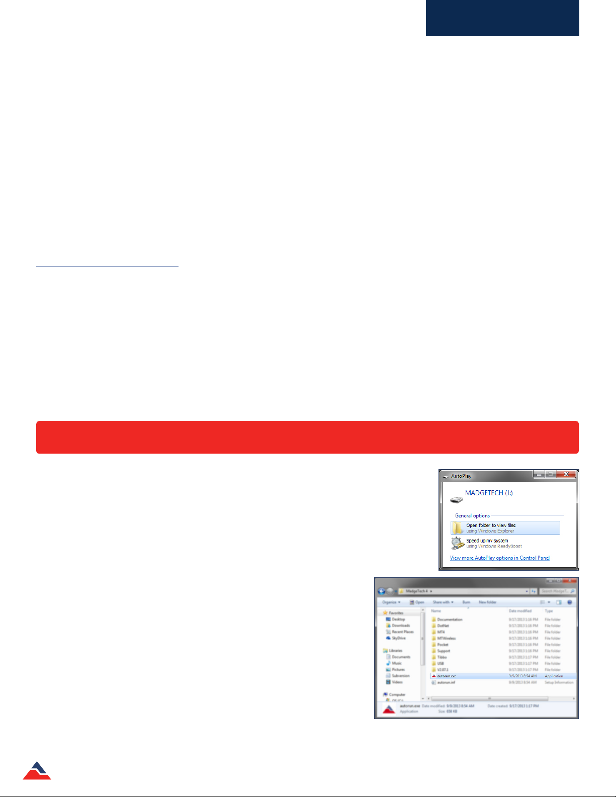
1. To begin installation, insert the ash drive labeled MadgeTech Data
Logger Soware Version 4.X.X into an available USB port. Aer a few
moments an AutoPlay box will open. (shown right)
2. In the AutoPlay box, click Open folder to view les to view the contents
of the
ash drive.
3. In the case that the AutoPlay is disabled, manually browse to the
MadgeTech ash drive by clicking on the Start button or Windows Icon,
navigate to Computer and double click the drive, MadgeTech, to see
the contents.
Double-click the autorun.exe (application) to launch the MadgeTech 4
Installer Options.
MadgeTech 4 Standard Soware Manual | MadgeTech, Inc. | www.madgetech.com
Autorun.exe le located on the MadgeTech USB drive
8
Page 9
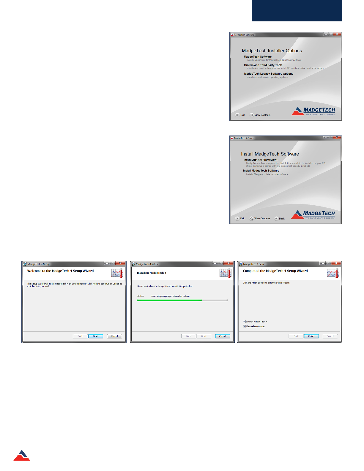
The MadgeTech installer options screen (shown right) will launch.
Choose the MadgeTech Soware option to install the MadgeTech 4 Standard
Data Logging Soware.
Choose the Drivers and Third Party Tools option to install drivers and soware
for use with USB interface cables and accessories.
The MadgeTech Legacy Soware Options oers installer options for older
operating systems.
Click MadgeTech Soware to open the Install MadgeTech Soware options
page. (shown right)
The MadgeTech 4 Soware requires the .Net 4.0 Framework to be installed on
the intended PC. The Windows 8 and Windows 10 operating system comes with
the 4.5 .Net Framework already installed. If the .Net 4.0 Framework has not
been installed on the PC, click the Install .Net 4.0 Framework option and walk
through the wizard installation steps.
Software Overview
(Note: If the .Net 4.0 Framework has already been installed and you attempt to run the Install .Net
4.0 Framework, a window asking to Repair or Remove the .Net 4.0 Framework will appear. It is
recommended to select the Cancel button when this page appears.)
Aer the .Net 4.0 Framework installation has been conrmed, click the Install
MadgeTech Soware option. Select English when prompted for a language
selection, then the Installation Wizard will walk through the installation steps to
install the soware.
The following are examples of the installation windows:
When the Installation Complete screen appears, click Finish to exit the wizard and return to the autorun, then Exit at the bottom
to close the autorun. The MadgeTech 4 Standard Soware is now installed on your PC.
MadgeTech 4 Standard Soware Manual | MadgeTech, Inc. | www.madgetech.com
9
Page 10
Software Overview
Installing the USB Interface Drivers
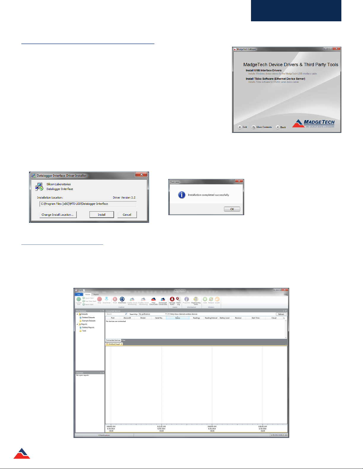
The USB interface drivers can easily be installed on the PC if they are not already
available and running.
From the MadgeTech Installer Options page, click Drivers and Third Party Tools
to open the MadgeTech Device Drivers and Third Party Tools page. (shown right)
The Install USB Interface Drivers options will install Windows device drivers for
the MadgeTech USB interface cable.
(Note: The Install Tibbo Soware (Ethernet Device Server) option will install Tibbo Soware for the DS202
serial device server. Installing the Tibbo soware would be required with the use of an IFC110 and the
MadgeTech 2 soware.)
Click Install USB Interface Drivers from the install screen.
The following dialog box will appear when the USB interface drivers have been successfully installed. (see below)
Starting the Software
To begin, launch the soware by simply double clicking the desktop icon, clicking the icon in the Quick Launch toolbar, or
clicking the icon in the MadgeTech folder within All Programs in the Start Menu. Once the soware is open, the user can make
any and all preference changes that are necessary.
MadgeTech 4 Standard Soware Manual | MadgeTech, Inc. | www.madgetech.com
10
Page 11

Software Overview
Shutting Down the Software
There are a few dierent ways to shut down the soware.
Shut Down: File Menu
If the current report has been saved, shutting down the soware by using the File menu will keep
the report settings set during that session. If the current report has unsaved report settings or
dataset, the soware will prompt the user to save before shutting down.
To shut down the soware using the le menu:
1. Click the File tab.
2. Click the Exit Application button in the bottom right corner of the menu.
Shut Down: X Button
If the current report has been saved, shutting down the soware by clicking the X button will keep the report settings set
during that session. If the current report has unsaved report settings or dataset, the soware will prompt the user to save
before shutting down.
To shut down the soware using the X button:
1. Click the X button in the top right hand corner of the soware screen.
Shut Down: Keyboard Shortcut
To shut down the soware using the keyboard shortcut:
1. Simultaneously press Alt+F4 on the keyboard.
2. If the current report has unsaved report settings or dataset, the soware will prompt
the user to save before shutting down.
Uninstalling the Software
Uninstalling the MadgeTech 4 Standard Soware is easy and can be
done through the operating system on the user's computer.
To uninstall the MadgeTech soware:
1. Click the Start menu.
2. Navigate to and select Control Panel.
3. Navigate to and select Programs and Features to display a list of
programs currently installed. (shown right)
Use the scroll bar to locate MadgeTech 4 in the list. Then right-click the
program within the list and select Uninstall. A message will appear.
(shown right)
Click Yes to uninstall the soware. Click No to keep the soware and
cancel the action.
Programs and Features screen
MadgeTech 4 Standard Soware Manual | MadgeTech, Inc. | www.madgetech.com
11
Page 12
Software Overview
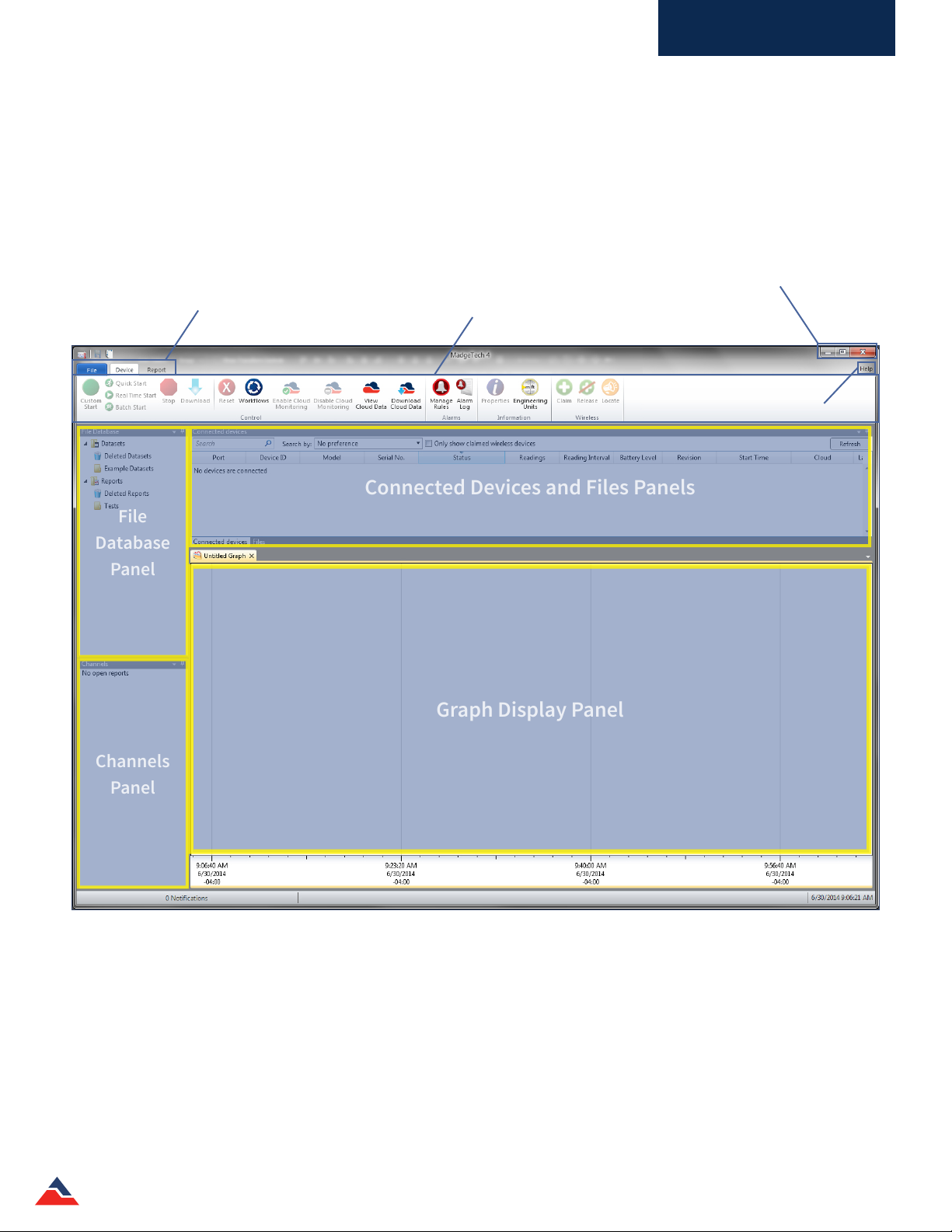
Graph Display Panel
Connected Devices and Files Panels
File
Database
Panel
Channels
Panel
Software Menus and Navigation
Each section of the soware will be explained briey in the following pages. Please refer to the soware help menu for more
information or troubleshooting.
Minimize, Full Screen and
Close option buttons
Help Button
Tab Options
Menu Bar
(Changes depending upon the
selected tab)
MadgeTech 4 Standard Soware Manual | MadgeTech, Inc. | www.madgetech.com
12
Page 13
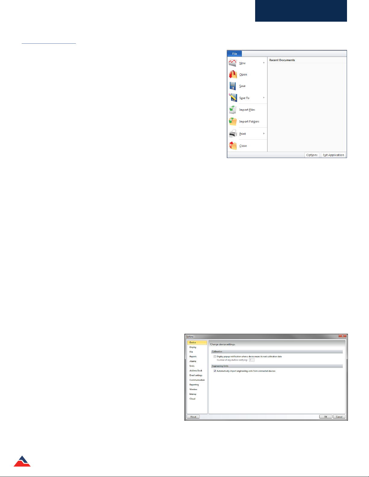
The File Menu
Within the rst upper le tab titled File, there are many dierent options
that appear. Below is a brief description of every item.
• New: Creates a new blank report.
• Open: Opens a report saved outside the soware.
• Save: Saves the le to the le database.
• Save To: Saves reports as an MTFF le.
• Import Files: Imports les from locations outside of the soware.
• Import Folder: Imports folders from locations outside of the soware.
• Print: Prints the selected open report.
• Close: Closes the selected open report.
• Recent Documents: The side bar will show any recent documents that have
been opened or saved.
• Options: Many soware settings and defaults can be managed and edited
here.
• Exit Application: Closes the soware.
Software Overview
File Tab
The Options Menu
The Options button, located at the bottom right section of the File tab, oers a variety of options that aect the appearance and
default settings of the soware.
• Device: Change device settings of a logger in regards to calibration notications and importing engineering units from the
currently connected devices.
• Display: Edit the default settings when the soware opens.
• Page display allows the user to choose what measurement the page display can be: Inches, Millimeters or Centimeters.
• Viewing data allows the user to edit the time format and channel grouping.
• Cooling ags allows the user to choose the default cooling ags that can be displayed.
• The Layout section allows the user to edit the ability to minimize to the system tray, the overall soware color scheme,
and resetting the screen layout.
• File: Change how les are imported and where the preferences and le database are located.
• Reports: Customize default report properties.
• Alarm: Congure pre-dened comments when acknowledging alarms.
• Units: Change the default colors for the various unit types.
• Address Book: Manage the contacts within the soware.
• Email Settings: Manage the server address, port and
email authentication settings.
• Communications: Congure and display detected
interfaces.
• Reporting: Change the soware problem and usage
reporting preferences.
• Wireless: Congure the timeouts of wireless timeouts.
• Interop: Soware built using the Windows
Communication Foundation (WCF) can retrieve real time
readings from data loggers connected to the MadgeTech
4 soware.
• Cloud: Login and manage MadgeTech Services Cloud account.
MadgeTech 4 Standard Soware Manual | MadgeTech, Inc. | www.madgetech.com
13
Page 14
Software Overview
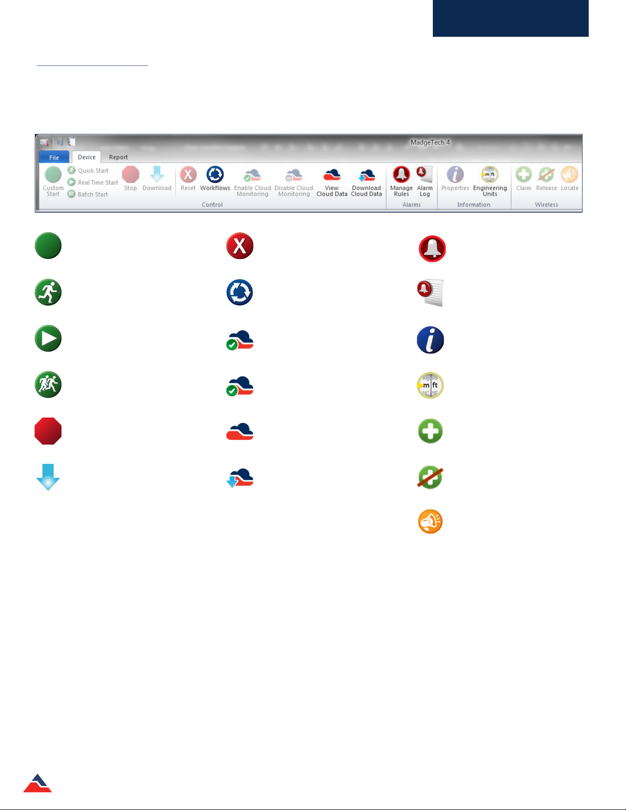
The Device Menu
The Device tab, located at the top of the menu bar, contains all of the features for managing devices. Within this tab are four
dierent sections: Control, Alarms, Information, and Wireless. Below is a list of commands and options found in the device
menu.
Custom Start - Start the selected
device(s) using custom settings.
Quick Start - Start the selected
device(s) using the current settings.
Real Time Start - Start the selected
device(s) in real time mode.
Batch Start - Automatically start
devices of the same type as they’re
connected.
Stop - Stop the selected device(s).
Download - Download recorded data
from the selected device(s).
Reset - Resets the selected device(s).
Workows - Manage device
automation workows.
Enable Cloud Monitoring - Enables the
data logger to be connected through
the Cloud Soware.
Disable Cloud Monitoring -
Disconnects the data logger from the
Cloud Soware.
View Cloud Data - View cloud data
through a web browser.
Download Cloud Data - Download
cloud data as a CSV le.
Manage Rules - Manage real time
alarm rules.
Alarm Log - Displays alarm notication
history.
Properties - View the properties and
settings of the selected device.
Engineering Units - Manage
engineering units.
Claim - Add the selected wireless
device(s) to the network.
Release - Remove the selected wireless
device(s) from the network.
Locate - Find or identify a wireless
device with an audible alarm.
MadgeTech 4 Standard Soware Manual | MadgeTech, Inc. | www.madgetech.com
14
Page 15
Software Overview
P
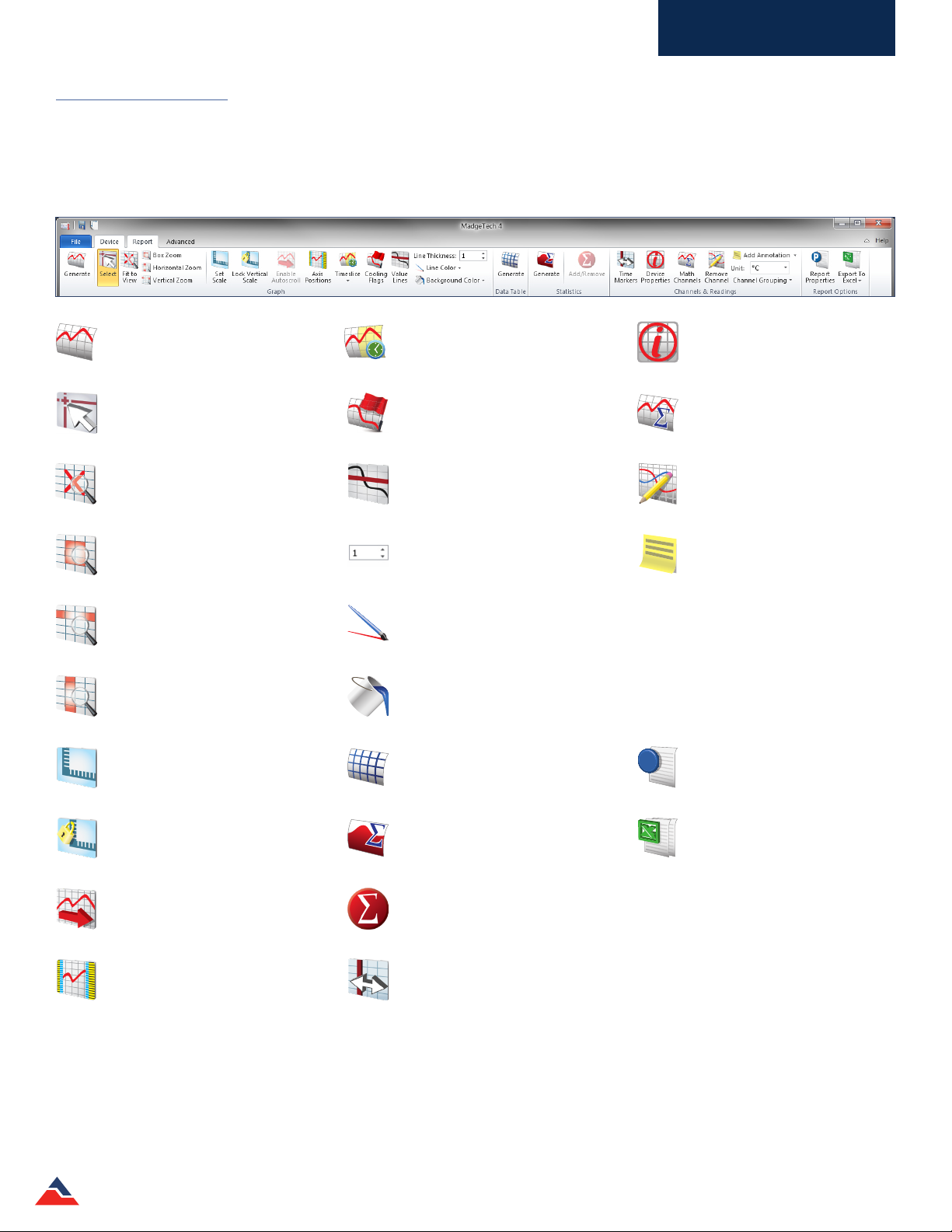
The Report Menu
The Report tab, located at the top of the menu bar, contains all of the features and options for managing reports. Within this tab
are ve dierent sections: Graph, Data Table, Statistics, Channels & Readings, and Report Options. Below is a list of commands
and options found in the report menu.
Generate - Generates a graph based on
the current report, or a blank graph if
no report is open.
Select - Change the cursor function to
select data points.
Fit to View - Zoom out to t all data
in view.
Box Zoom - Change the cursor function
to zoom in on a selected area.
Horizontal Zoom - Change the cursor
function to zoom in on a selected
length of time.
Vertical Zoom - Change the cursor
function to zoom in on a selected unit
range.
Set Scale - Set the scale of the graph.
Timeslice - Manage timeslice options.
Cooling Flags - Set annotations for
multiple temperature cooling points.
Value Lines - Horizontal lines that
are xed for Minimum, Maximum &
Average Line values.
Line Thickness - Changes the thickness
of the value lines in the graph.
Line Color - Changes the color of the
value lines in the graph.
Background Color - Changes the
background color of the graph.
Generate - Generate a new grid based
on the current report, or a blank grid if
no report is open.
Device Properties - View the properties
of the selected channel’s associated
device.
Math Channels - Manage channels that
generate values based on specied
calculations.
Remove Channels - Remove the
selected channel from the current
report.
Add Annotation - Add a comment to
the graph.
Unit - Change the unit for the selected
channel.
Channel Grouping - Change how the
channels are grouped; Serial Number,
Device ID and Device name.
Report Properties - View details about
the current report.
Lock Vertical Scale - Lock the vertical
scale of the graph.
Enable Autoscroll - Allow the graph to
automatically scroll along the time axis
as real time data points are added.
Axis Positions - Change which side of
the graph each axis is positioned.
MadgeTech 4 Standard Soware Manual | MadgeTech, Inc. | www.madgetech.com
Generate - Generate a new statistics
view based on the current report, or a
blank view if no report is open.
Add/Remove - Manage custom statistic
information.
Time Markers - Allows graphs to
be displayed with cycle duration
properties.
Export to Excel® - Copy the data of the
current report to Microso Excel®.
15
Page 16
Software Overview
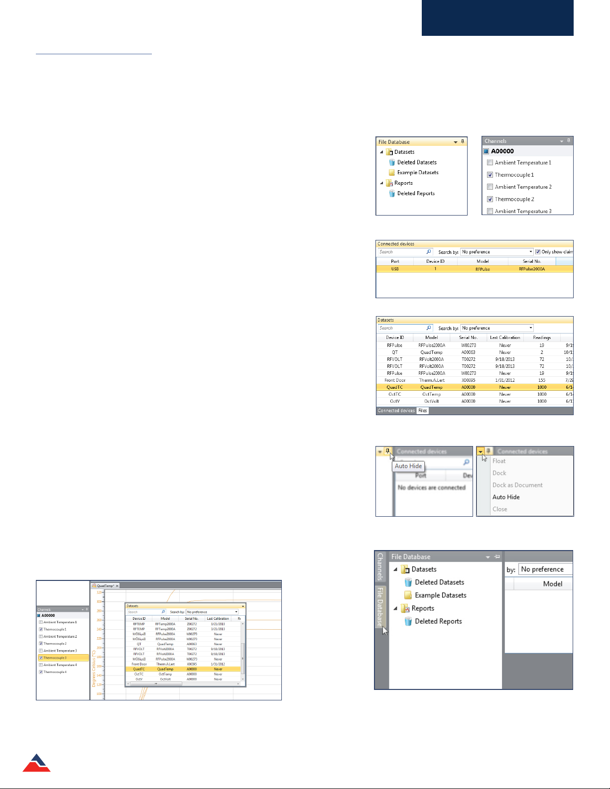
Screen Navigation
The MadgeTech 4 soware oers a display with nearly limitless report capabilities and customization features. Users now have
the opportunity to arrange the display screen to suit specic needs such as size, placement, and information accessibility.
File Database
• The File Database panel contains several dierent folders where reports
can be saved or deleted. Users can also create new folders to help organize
datasets and reports.
Channels Panel
• The Channels panel displays the dierent panels within the current open
report. If no report is open, the panel will be blank.
Connected Devices
• The Connected Devices panel displays a list of devices that are connected to
the PC or available through wireless transmission. A device in this panel must
be selected in order to enable any device specic features.
File Database Panel Channels Panel
Files
• The Files panel displays the contents of the folder selected in the File
Database panel.
Users can toggle between the Files panel and Connected Devices panel
depending on their intended use of the soware at that time.
On each of the panels header bar there is a downward pointing arrow icon and
a pin icon. Clicking on the pin icon will cause the panel to auto hide
and become a tab in the le margin. To view the contents when the panel is
hidden, hover the mouse over the hidden panel’s header. A context menu is
available with the following options:
• Float: This allows the selected panel to Float and can be moved anywhere
on the screen. A panel can also oat by clicking on its header, holding and
dragging it anywhere on the screen, then releasing it. (shown below)
• Dock: This option locks the selected panel in its original position.
• Dock As Document: This option adds a panel to the report tab group.
• Auto Hide: This option hides the panel so only the header is visible.
• Close: This option closes the panel.
Connected Devices Panel
Files Panel
Hovering over the pin icon will
allow the panel to be hidden
Hovering over the arrow icon will
show a variety of options
Floating Datasets Panel
MadgeTech 4 Standard Soware Manual | MadgeTech, Inc. | www.madgetech.com
Hovering over a hidden panel will display the contents of that panel.
Note: the pin icon now points to the le.
16
Page 17
Software Overview
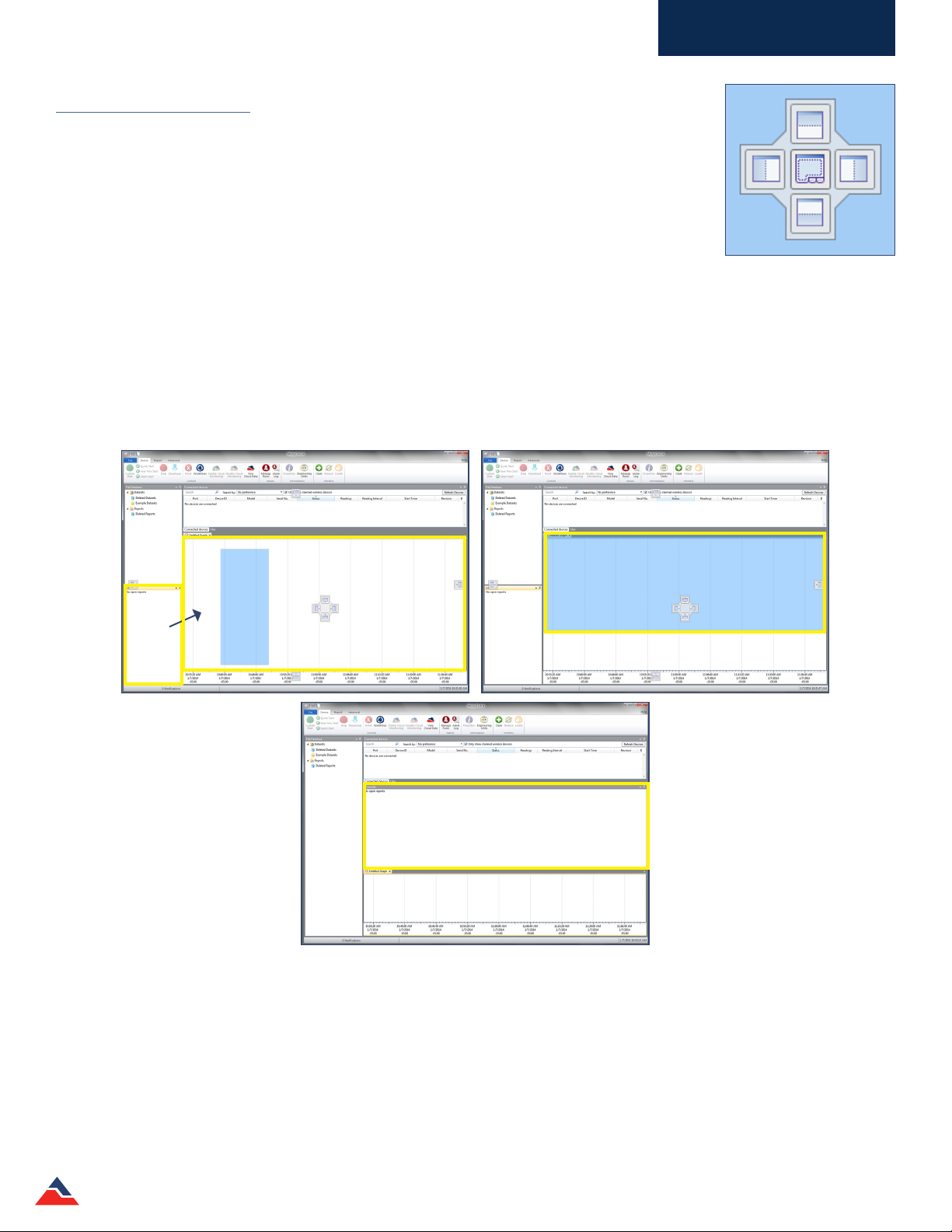
Rearranging Panels
In addition to the hiding and oating panel options, panels can also be manually rearranged to meet
user preferences.
To rearrange a panel:
1. Click and hold the header of the panel.
2. Move the mouse in the direction of where the panel’s new location will be. A highlighted blue
section will move with the mouse to act as a preview for the panel. Continue to move the mouse
until the following screen appears.
Move the mouse to the desired option, then release the mouse. The top option will place the selected panel above the panel in
which the image appeared in. The right option will place the selected panel to the right of that panel, the le option will place the
selected panel to the le of that panel, the bottom option will place the selected panel below that panel, and the center option
will place the selected panel on top of that panel. (Note: Not all panels support the center option.) Below are sample screens of the steps to
rearrange the Channels panel. Now the Channels panel is above the chart window instead of to the le as it was originally.
Optional Placement of the panels
MadgeTech 4 Standard Soware Manual | MadgeTech, Inc. | www.madgetech.com
17
Page 18
Software Overview
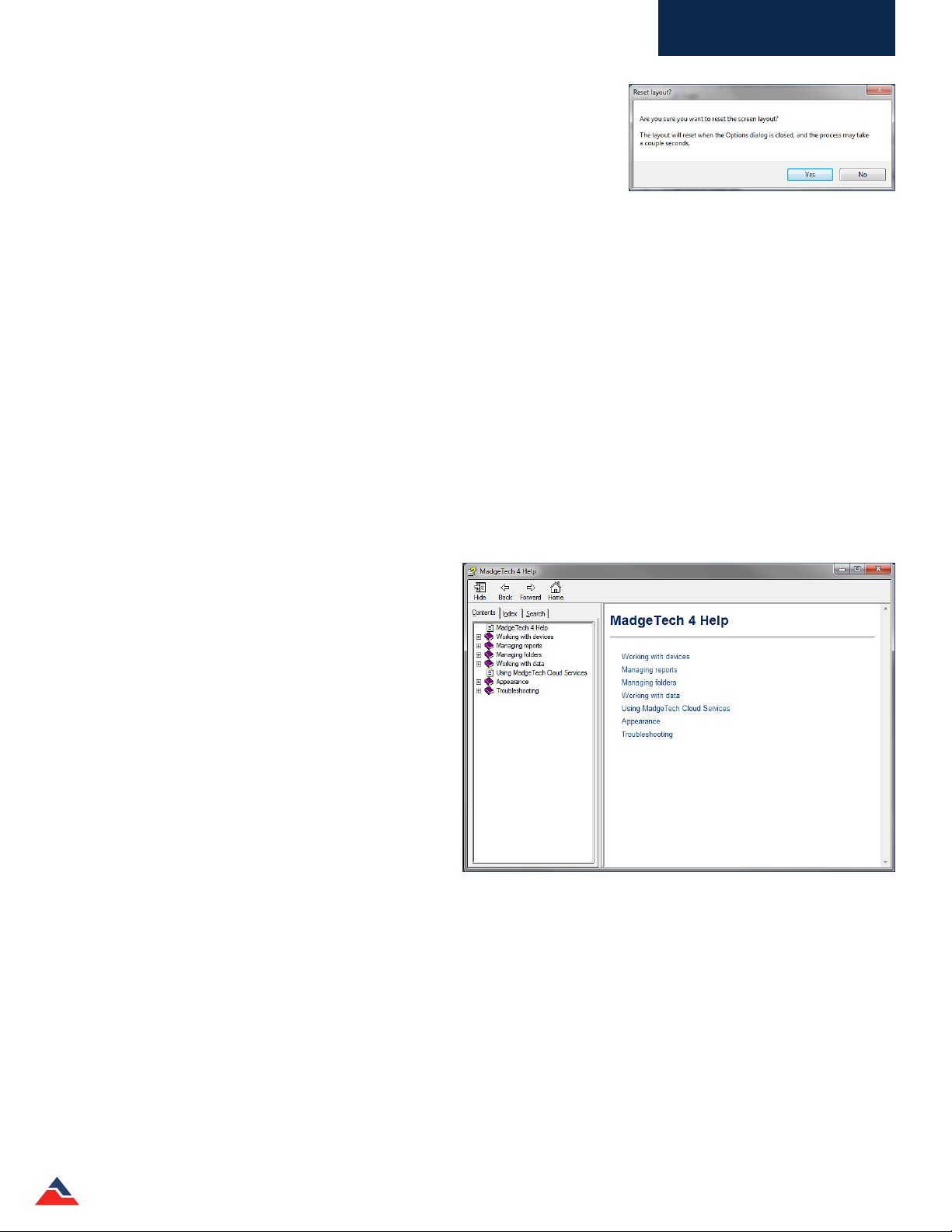
Restoring Default Windows
The soware has an easy way to restore the panels of the soware to the default
screen layout.
To restore default windows:
1. Click the File tab and then click Options.
2. Click the Display tab.
3. Scroll to the bottom and select Reset screen layout. The soware will display a prompt to conrm the request. Select Yes.
4. It will return to the options panel, select OK to apply the changes. Any unsaved data will also be prompted by the soware to
be saved.
5. If the report is open and has not been saved, the reset screen layout will not be applied.
The Help Menu
The MadgeTech 4 soware oers a comprehensive help menu to answer any questions encountered while using the MadgeTech
soware. Users have the ability to search directly using key words or utilize the pre-formulated categories to navigate and nd a
solution to the problem at hand.
• Using the contents portion of the help menu, there are
various sections that cover the most common topics.
• MadgeTech 4 Help
• Working with devices
• Managing reports
• Managing folders
• Working with data
• Using MadgeTech Cloud Services
• Appearance
• Troubleshooting
• The index portion of the help menu allows
searching for one word.
• The search option of the help menu allows the user to
insert a question or phrase.
For more details about the help section, refer to Managing Data, Folders and Reports, Maintenance, and Troubleshooting
sections of the manual.
MadgeTech 4 Standard Soware Manual | MadgeTech, Inc. | www.madgetech.com
18
Page 19

Working With Devices
Working With Devices
In the MadgeTech 4 Soware, data can be viewed in graphical or tabular formats as well as summary and statistics views, which
are available for further analysis. The soware features exporting to Microso Excel®, data annotation, digital
calibration and more. By transitioning information seamlessly from MadgeTech 2 to MadgeTech 4 (CSV les only), users can view
their data like never before.
Connecting and Disconnecting a Device
Each data logger must be connected to the PC to allow communication with the device. The MadgeTech wireless data logger
series can communicate wirelessly using a MadgeTech transceiver. (sold separately)
The following steps should be used for connecting and disconnecting data loggers using the appropriate interface cable for
that device.
To connect a device:
1. Plug the interface cable into an available COM or USB port on the computer.
2. Plug the stereo jack end of the interface cable into the device, or insert the data logger into the interface docking station.
(Note: The connection from the interface cable to the data logger varies depending on the interface cable and data logger being used.)
3. Once the data logger is connected to the PC, it will appear in the Connected devices panel.
To disconnect a device:
1. Unplug the stereo plug end of the interface cable from the data logger, or remove the data logger from the interface
docking station. (Note: Do not disconnect the data logger while device settings are being applied.)
MadgeTech 4 Standard Soware Manual | MadgeTech, Inc. | www.madgetech.com
19
Page 20
Working With Devices
Start a Device
When starting a device to record data, several options and start methods are available. Start settings can be specied before
deploying the device. Choose Custom Start to select or modify logging options or the devices can be started using the current
settings by selecting either Real Time Start or Batch Start. The Real Time Start option allows the devices to report readings back
to the central PC instantly. The Batch Start option allows devices of the same model to be programmed with the same custom
start settings.
Multiple devices can be selected by holding the Ctrl or Shi key, selecting additional devices, or pressing the arrow keys.
However, the devices selected must all be the same model in order for the start options to become available.
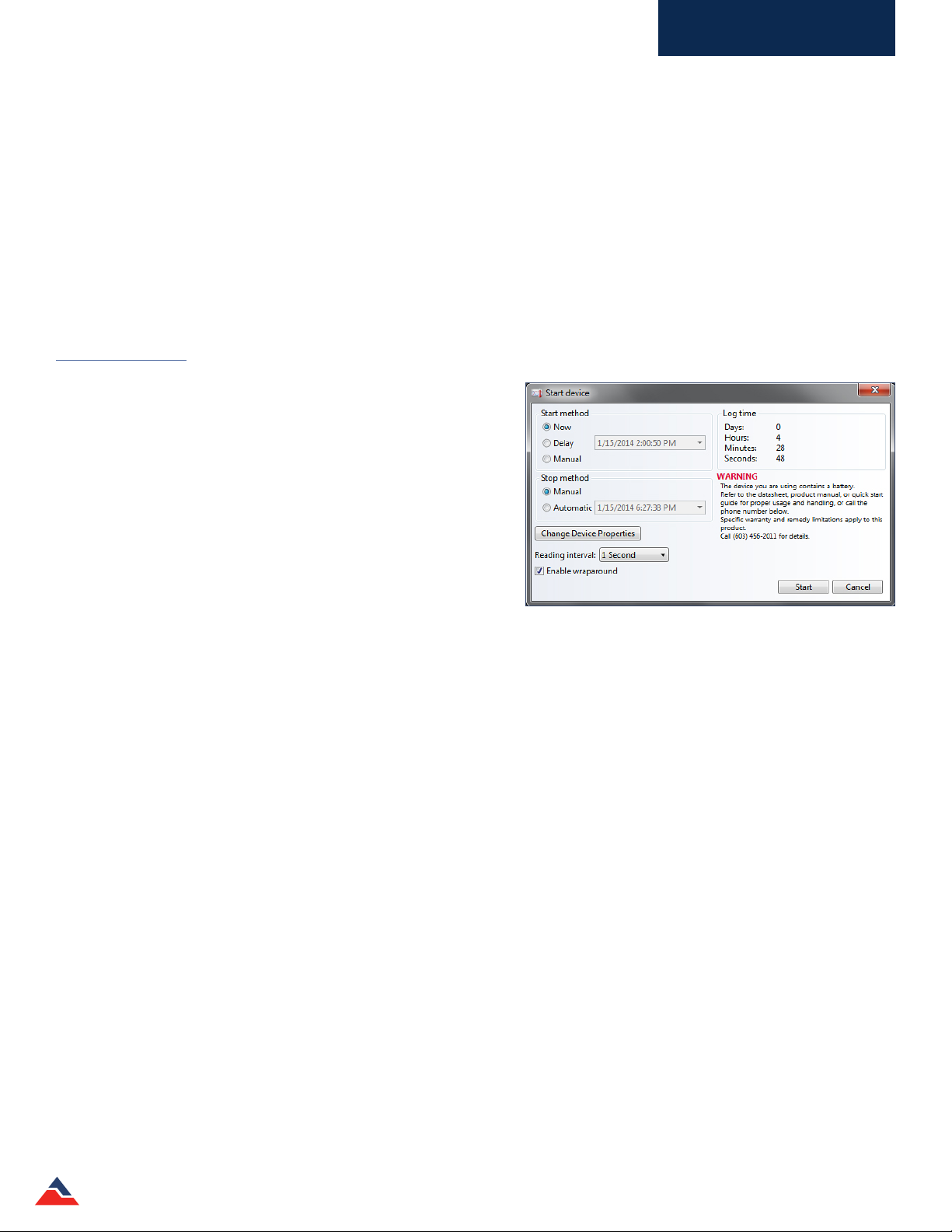
Custom Start
When starting a device using custom settings, the user can specify
when the device starts by choosing to start immediately or having a
delayed start and then a reading interval, which will vary depending
on the device and application. Additional options, such as the
stop method and enabling memory wraparound, (overwriting the
internal memory when the reading capacity is reached) are available
depending on the properties of the selected device. (shown right)
Immediate Start
To start a device using custom settings for an immediate start:
1. In the Connected devices panel, select the device to start. The
device should be highlighted.
2. On the Device tab, in the Control group, click Custom Start. Users can also right-click on the device and select Start, then
Custom Start in the context menu.
3. Specify all desired settings.
4. Click Start.
5. When the device has been started, the status in the Connected devices panel will read Running.
Manual and Delay Start
Depending on the device, the user can manually start a data logger or perform a delayed start using the Custom Start option.
Manual Start
A data logger with the manual start function needs to be programmed in order for a Manual Start to be performed.
To manually start a device:
1. In the Connected devices panel, select the device. Conrm that the intended device is highlighted.
2. On the Device tab, in the Control group, click Custom Start. Users can also right-click on the device and select Start, and then
Custom Start in the context menu.
3. Under the Start method section within the Start device screen, select the Manual radio button.
4. Choose any additional necessary start settings (such as reading interval, memory wraparound, stop method, etc.).
5. Click the Start button. The Start device box will close and the status column in the Connected devices panel will read,
Waiting for manual start.
6. To begin recording, please refer to the manual start method in the product information card provided with the device.
MadgeTech 4 Standard Soware Manual | MadgeTech, Inc. | www.madgetech.com
20
Page 21
Working With Devices
Delay Start
When using the Delay Start method, the user can decide when the data logger will begin recording by setting a time in the
Custom Start window. This method does not require the user to be present to start the device, as it will automatically start at
the selected time.
To Delay Start a device:
1. In the Connected devices panel, select the intended device. Conrm that the intended device is highlighted.
2. On the Device tab, in the Control group, click Custom Start. Users can also right-click on the device and select Start, and then
Custom Start in the context menu.
3. Under the Start method section within the Start device screen, select the Delay radio button.
4. Click the dropdown menu beside the Delay radio button and choose the intended start date and time.
5. Choose any other necessary start settings (such as reading interval, memory wraparound, stop method, etc.)
6. Click the Start button.
7. The status column in the Connected devices panel will read Waiting to start.
8. Once the selected start time has passed, click the Refresh Devices button if the device does not appear. (Note: A wireless device will
update on its own, otherwise the duration of the refresh will be long.)
9. The status column in the Connected devices panel will read Running.
Quick Start
When a device is started using the Quick Start option, it will start immediately using the most recent Custom Start settings. It is
important to make sure that the selected devices are properly congured before using Quick Start.
To Quick Start a device:
1. In the Connected Devices panel, select the intended device. Conrm that the intended device is highlighted.
2. On the Device tab, in the Control group, click Quick Start. Users can also right-click on the device and select Start, then Quick
Start in the context menu.
3. When the device has properly been started, its status in the Connected devices panel will read Running.
Real Time Start
When a device is started in Real Time, reading data is transferred directly to the soware in the form of a dataset and stored in the
soware's internal database. The data can be viewed as a report at any time and will automatically update as new readings are
received.
Wireless and non-wireless devices function dierently when started in Real Time.
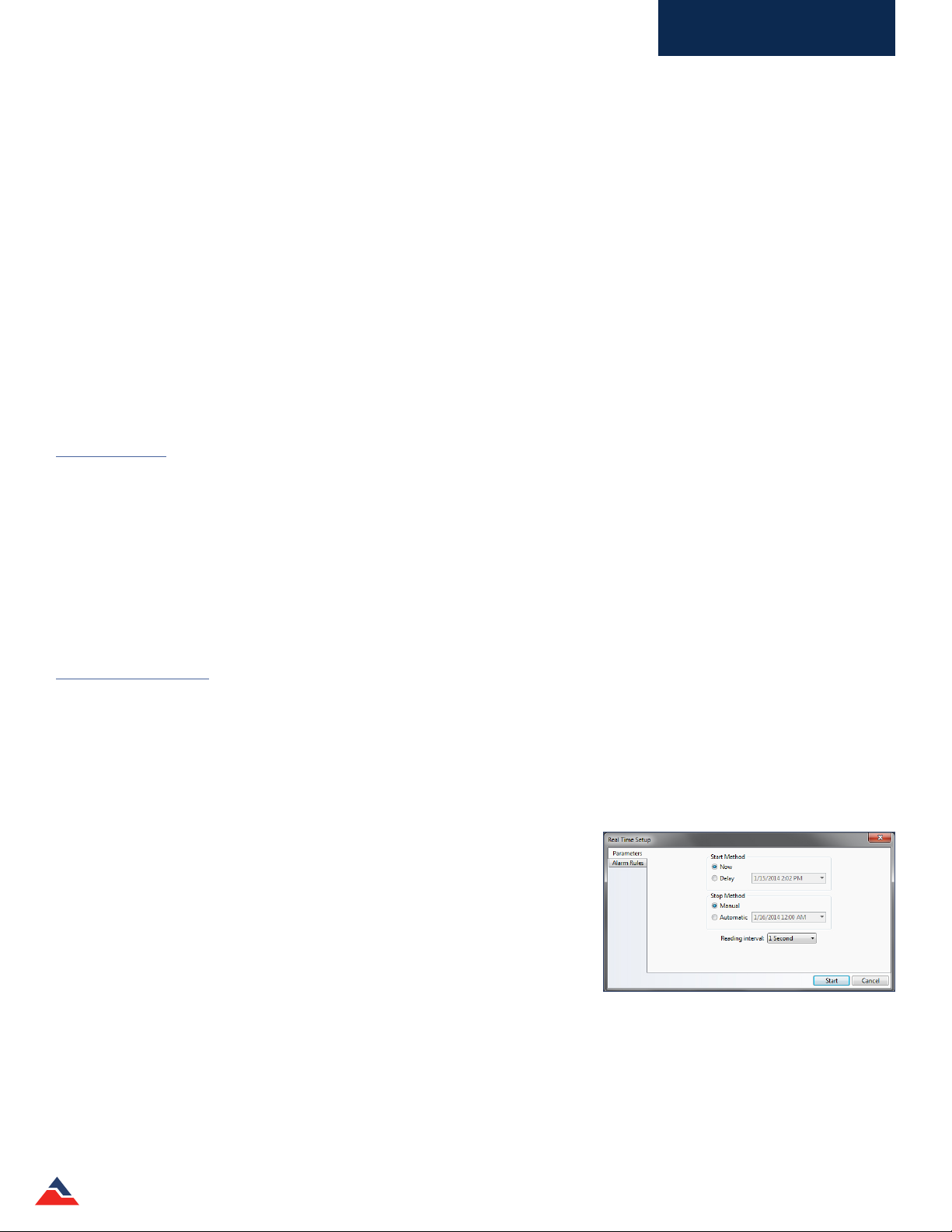
To start a device in Real Time:
1. In the Connected devices panel, select the intended device. Conrm that the
intended device is highlighted.
2. On the Device tab, in the Control group, click Real Time Start. Users can also
right-click on the device and select Start, and then Real Time Start in the
context menu.
3. Specify device start and stop preferences, as well as the reading interval in the
Parameters tab. Alarm rules can be
congured in the Alarm Rules tab. (shown right) (Note: For more information about
adding, changing or removing alarm rules, please refer to the Alarms section of this manual.)
4. Click Start button.
5. If Display a graph when Real Time logging begins is checked in the Display tab of the Options dialog, a graph will
automatically appear containing the real time data of the devices selected.
6. When the device has properly been started its status in the Connected devices panel will read Real Time.
MadgeTech 4 Standard Soware Manual | MadgeTech, Inc. | www.madgetech.com
21
Page 22
Working With Devices
A device can also be started in Real Time when it is already running:
Under certain conditions a device can be started in Real Time when it is already running, if it is not a wireless device. The device must be
physically plugged into the computer, wraparound must be disabled and the reading interval must be 2 seconds or slower.
1. In the Connected devices panel, select the Running device requiring a Real Time start option. Its status will read Running.
2. In the Device tab, in the Control group, click Real Time Start. (Note: The status will now read Real Time.)
3. In order to stop the device, Stop must be clicked twice.
Batch Start
When using the Batch Start option, one device is programmed and will specify the settings that other similar devices will use.
Selecting multiple devices before beginning a batch start is not required. (Note: Only devices of the same model and rmware can be Batch
Started together.)
A Batch Start is useful when a user has many duplicate or same model devices that need to be started with the same settings.
The Batch Start option allows the user to start all of the devices with the push of one button, instead of individually changing the
settings and starting each device individually, saving valuable time and eort.
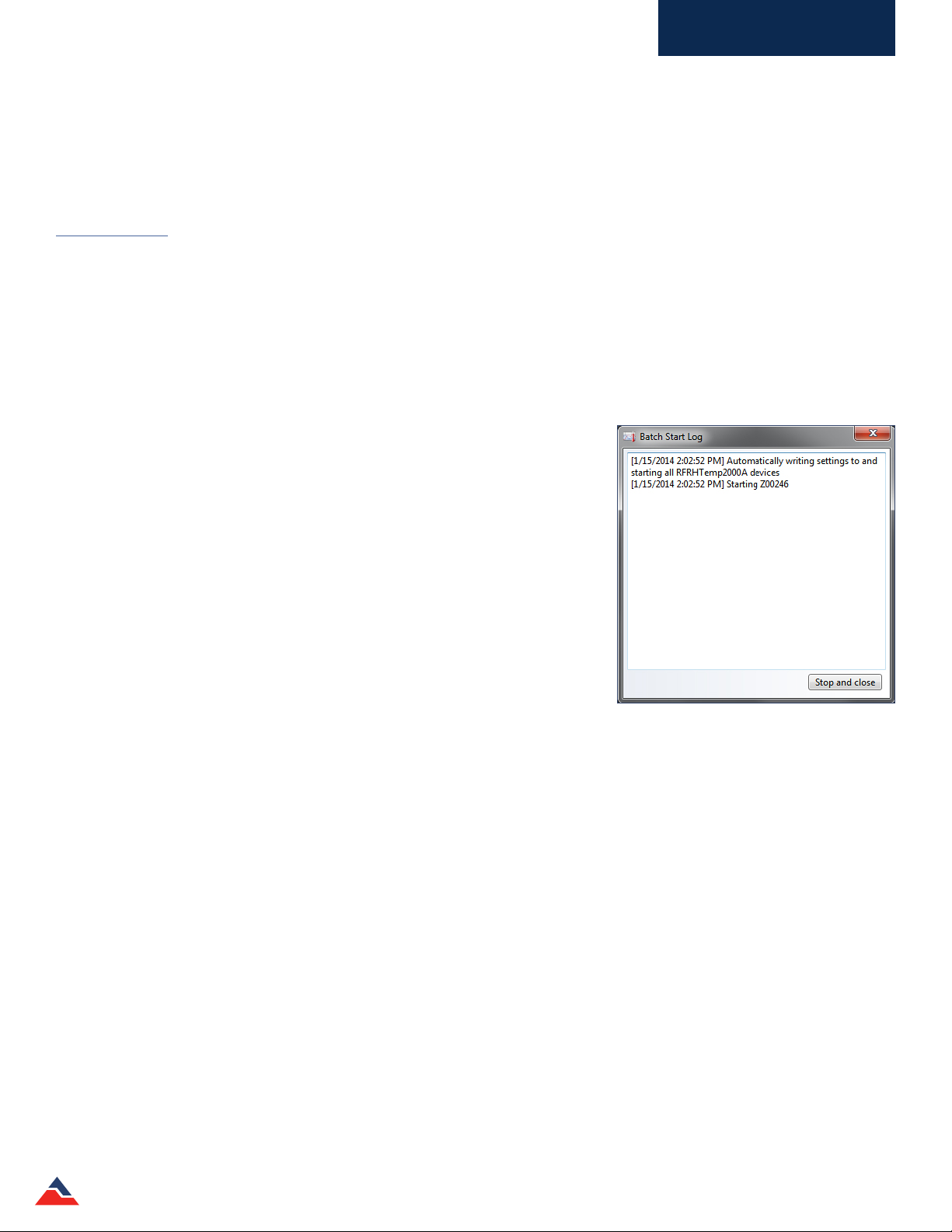
The Batch Start will have the same start device settings screen as the Custom
Start option. Additionally, aer the Start button is clicked, a Batch Start Log
dialog box will appear to inform the user when each device is starting and when it
actually has been started. (shown right)
To begin a Batch Start:
1. In the Connected devices panel, select the intended device to be used as a
basis for the Batch Start.
2. On the Device tab, in the Control group, click Batch Start. Users can also
right-click on the device and select Start, then Batch Start in the context
menu.
3. Congure settings and start the device that is plugged in by clicking Start.
4. Remove the rst data logger from the docking station, then place the next
data logger into the docking station. When the devices have properly been
started their status in the Connected devices panel will read Running.
Repeat this step until all of the intended devices have been started.
Any devices plugged into the PC that are the same model as the device used to congure the Batch Start will automatically start.
Each device shown as Started or Waiting to Start can then be unplugged.
The device will begin recording data once it has been started. Depending on the stop method selected, the device will continue to
collect data until manually stopped, it reaches memory capacity or it has reached the stop parameters chosen by the user. Once
the device has been stopped, the data collected can be downloaded into a dataset and used to generate any type of report.
MadgeTech 4 Standard Soware Manual | MadgeTech, Inc. | www.madgetech.com
22
Page 23

Working With Devices
Stop a Device
When devices are currently recording data, running in Real Time, or waiting to start, users can choose to stop recording. Devices
that are stopped will no longer record data until congured to start again. The stop methods available will vary by model, but can
include: Manual Stop, Automatic Stop, and Readings Stop. These stop methods are designated when the device is started.
Multiple devices can be selected to stop by holding the Ctrl or Shi key and either selecting additional devices or pressing the
arrow keys. All of the devices that have been selected will be highlighted in the Connected devices panel.
Manual Stop
The Manual stop option is convenient and easy to set up. There is no information that needs to be entered in comparison to the
Automatic or Readings Stop methods. Manual stop is always available even when other stop methods are selected at startup.
To congure Manual Stop during startup:
1. In the Custom Start box, select the Manual radio button under the Stop Method section.
To manually stop a device:
1. In the Connected devices panel, select the intended device to stop.
2. On the Device tab, in the Control group, click Stop. Users can also right-click on the device and select Stop in the context
menu. (Note: With 101A data loggers, the Manual Stop option can enable a pushbutton stop if the Manual Start option is also selected.)
If a device is both recording data and running in Real Time, Stop must be clicked twice in order to stop the device. Clicking Stop
once will only stop the Real Time recording, selecting Stop the second time will stop the data from recording.
Automatic Stop
The Automatic Stop method is time dependent. Users can set a future point in time, to stop a logger from recording. The user
does not need to manually stop the device, as it will stop automatically.
To congure the Automatic Stop method:
1. In the Custom Start box, select the Automatic radio button under the Stop Method section.
2. In the dropdown menu next to the Automatic radio button, select the time when the device should stop recording.
3. To conrm the device has stopped recording, click the Refresh Devices button in the Connected devices panel. Now the sta-
tus column in the Connected devices panel will read Stopped.
Readings Stop Method
The Readings Stop method is dependent on the number of readings the device records. For example, if the duration of 20 is
entered into the readings text box, the device will stop recording once it records 20 readings.
To congure the Readings Stop Method:
1. In the Custom devices box, select the Readings radio button under the Stop Method section.
2. In the text box next to the Readings radio button, enter the number of readings the data logger should record
before stopping.
3. To conrm the number of readings have been recorded, click the Refresh Devices button in the Connected devices panel.
4. Now the status column in the Connected devices panel will read Stopped and the number of readings listed in the
Readings column will match what was entered in the Start device box.
MadgeTech 4 Standard Soware Manual | MadgeTech, Inc. | www.madgetech.com
23
Page 24
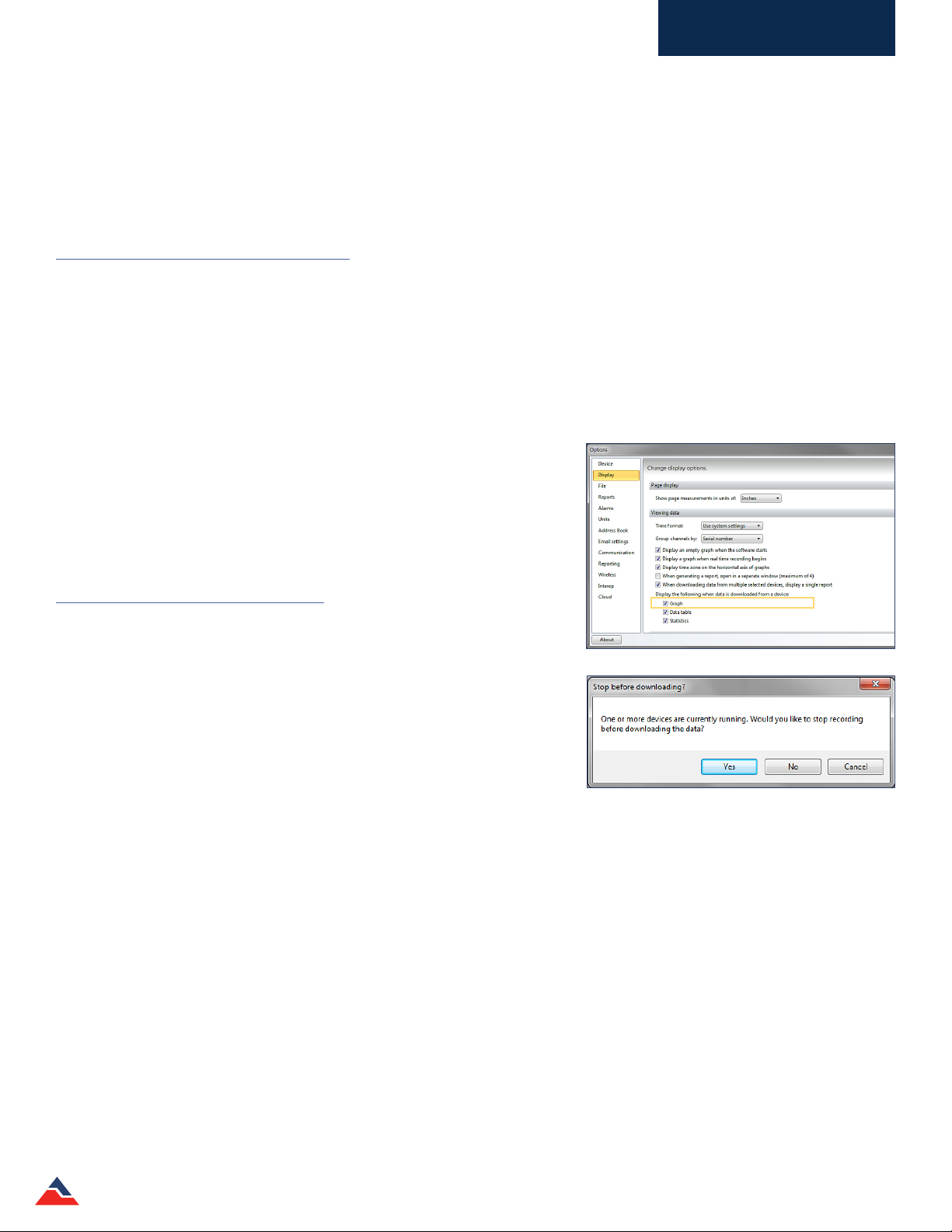
Working With Devices
Downloading Data
When the data logger is recording data, it stores the readings in its internal memory. To view the data, it must be downloaded
from the device and viewed as a graph, a data table, or statistics report in the MadgeTech soware. Downloaded data will remain
stored on the device until the device is reset or restarted. (Note: The MadgeTech Soware will not download the same data more than once.)
Download Data from a Device
To download data from a device:
1. In the Connected devices panel, select the intended device to download data from.
2. On the Device tab, in the Control group, click Download. Users can also right-click the device and select Download in the
context menu.
Automatically Display Reports of Data that have just been Downloaded
The user can also choose to have reports automatically appear to display data that have just been downloaded.
To congure the appearance of reports:
1. Click the File tab, then click Options.
2. From the Options screen, click Display.
3. In the Viewing Data section, select the check box next to each report type
the user wants to automatically open when data is downloaded from
a device.
Download While Recording
Certain devices have the ability to download data in the soware while
recording. The reading interval must be 2 seconds or slower, and the memory
wraparound must be disabled.
To download data while the device is still recording:
1. In the Connected devices panel, select the intended device to download
data from. Conrm the intended device has been selected by making sure
the device is highlighted.
2. On the Device tab, in the Control group, click Download. To the right is an
example of the following dialog box that will appear, asking to stop the device from recording.
3. Click Yes to stop the data logger and download the data. Click No to download the data and have the data logger continue to
record. Click Cancel to neither stop the device nor download any data.
Reset a Device
When the data stored in a device is no longer needed or resetting the status of alarms and triggers is required, the device can be
reset. If the device is currently recording, it will stop before resetting. Once a device is reset, the stored reading data cannot be
recovered, so always conrm that all data is downloaded and saved before resetting the device.
To reset a device:
1. In the Connected devices panel, select the intended device to reset.
2. On the Device tab, in the Control group, click Reset. Users can also right-click the device and select Reset in the context menu.
MadgeTech 4 Standard Soware Manual | MadgeTech, Inc. | www.madgetech.com
24
Page 25
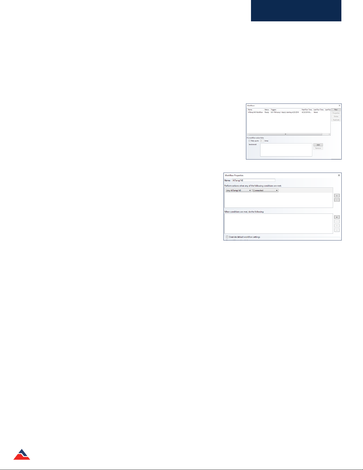
Working With Devices
Workflows
The Workows feature allows the user to automate tasks to eiciently download data, create reports and more. A Workow is a
saved set of instructions that tell the soware to perform tasks when specied conditions are met. Workows can be scheduled to
run at specic dates and times or when specic data loggers are connected to the PC. (Note: The MadgeTech Soware must be running for a
scheduled Workow to execute.)
Adding a Workflow
To add a workow to the soware:
1. On the Device tab, in the Control group, click the Workows icon.
2. Select New on the right hand side of the window, and do the following:
a. Enter a name in the Name box
b. Select the conditions that need to be met before the actions occur.
c. Select which actions will occur.
3. Click Ok.
Changing a Workflow
To change a workow in the soware:
1. On the Device tab, in the Control group, click the Workows icon.
2. Select the intended workow to change. (Note: A workow must be disabled before
it can be edited)
3. Click Properties and change the workow to t the desired preferences.
4. Click Ok.
Disabling a Workflow
To toggle whether a workow is enabled or disabled in the soware:
1. On the Device tab, in the Control group, click the Workows icon.
2. Select the intended workow to enable or disable.
3. Click Enable or Disable, depending on the current status of the workow.
Duplicating a Workflow
To duplicate a workow:
1. On the Device tab, in the Control group, click the Workows icon.
2. Select the intended workow to duplicate.
3. Click Duplicate. In the box that appears, change the workow settings to t desired preferences.
4. Click Ok.
Manually Running a Workflow
When a workow needs to be performed prior to meeting the condition requirements that were set, a workow can be run
manually.
To manually run a workow in the soware:
1. On the Device tab, in the Control group, click the Workows icon.
2. Select the intended workow to manually run. (Note: A workow must be enabled and not already running before it can be manually run.)
3. Click Run.
Deleting a Workflow
To delete a workow:
1. On the Device tab, in the Control group, click the Workows icon.
2. Select the intended workow to remove and select Delete.
MadgeTech 4 Standard Soware Manual | MadgeTech, Inc. | www.madgetech.com
25
Page 26

Working With Devices
Calibration
MadgeTech data loggers must be calibrated annually (at minimum). MadgeTech oers custom calibration services or the ability to
calibrate the device through the soware. Most data loggers can be calibrated through the soware, however depending on the
application, it is recommended that the devices be serviced by the MadgeTech Calibration Lab.
Calibration parameters, as well as the last calibration date, are stored within the device's non-volatile memory and can be
accessed through the soware. The soware also allows the device to maintain calibration while being used on any computer.
Most data loggers can be eectively calibrated using a single point to correct an oset. In some cases two points may be used
to correct for gain and oset errors. (Note: In most cases a very stable environment and accurate reference are required to perform an accurate
calibration. MadgeTech cannot guarantee the accuracy of any device calibrated outside of MadgeTech.)
There are two methods to input the calibration data into the device. First is the Gain and Oset option, which allows the user to enter
a gain and oset directly when calibrating. Second, the High and Low Values option. The calculation used for calibration is x=(y-b)/m.
The values these letters represent are seen below:
• x=calibrated value
• y=original device measurement
• b=oset
• m=gain
Another way of visualizing this calculation is:
• Calibrated value= (reading-oset)/gain
Gain and Offset Values
The default gain of 1 and oset of 0 do not aect the readings the device takes. The device should be set to the default gain of 1
and oset of 0 before taking measurements used for a calibration adjustment.
High and Low Values
The alternative to entering gain and oset values directly is letting the soware calculate them by entering device readings at
two reference points using the High and Low Values option. These reference points are called High and Low because devices are
generally tested at a low-range and a high-range value.
Example: A user wants to calibrate a HiTemp150. The low setting the user decides to use is 50 ˚C and the high setting the user
decides to use is 150 ˚C. These values are the reference values. At a stable environmental temperature of 50 ˚C, the device readings are 50.17 ˚C. At 150 ˚C the device is reporting 149.98 ˚C. The device readings for this example would be 50.17 and 149.98.
Using the above data, the user would ll in the following information on the calibration screen, assuming a unit of ˚C:
Low
• Reference value: 50
• Device reading: 50.17
High
• Reference value: 150
• Device readings: 149.98
Using these values, the soware calculates the gain and oset values and writes them to the device. The gain and oset values will
be subtracted or added to each reading downloaded from the device, and the data will be correct without any further manipulation.
MadgeTech 4 Standard Soware Manual | MadgeTech, Inc. | www.madgetech.com
26
Page 27
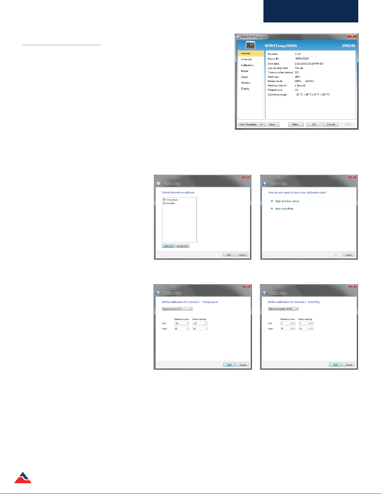
Working With Devices
Calibrating a Device
Devices need to be calibrated on a regular basis to ensure readings are
accurate. If device sensor information or other specications are provided with
the logger, the user can calibrate a device themselves. Devices can also
be sent back to the MadgeTech Calibration Lab for calibration as well for
custom and certied calibrations.
For a user to calibrate a device with the soware:
1. In the Connected devices panel, select the intended device to calibrate.
2. On the Device tab, in the Information group, click Properties. Users
can also right-click on the selected device and click Properties in the
context menu.
3. Click the Calibration tab. (shown right) (Note: If the Calibration tab is missing, the device does not need to be calibrated. Recording the current values
is recommended, so the original calibration values can be restored if desired.)
4. Click the Calibrate button.
A series of Calibrate a device windows will
appear. If the device has more than one
channel, select the intended channels to
calibrate. (shown right)
Next, decide how to input the calibration data.
Refer to the explanations previously outlined in
this section to choose the appropriate
option.
If the High and Low values option is selected,
the following screens will appear:
(Note: Depending on the device, the number of screens and
units shown will be dierent based on the dierent channels
the devices have.)
Select the intended channels to calibrate. If there is
more than one, select all that apply.
Select the input of the calibration data: High/Low
Values or Gain/Oset.
MadgeTech 4 Standard Soware Manual | MadgeTech, Inc. | www.madgetech.com
27
Page 28

Working With Devices
When the Conrm Calibration Settings screen appears, click Write and the following message will be displayed:
If the Gain and oset option is selected, the following screens will appear:
(Note: Depending on the device, the number of screens and units shown will be dierent because of the dierent channels each device has.)
When the Conrm calibration settings screen appears, click Write and the following message will appear:
MadgeTech 4 Standard Soware Manual | MadgeTech, Inc. | www.madgetech.com
28
Page 29

Working With Devices
Software Alarm Rules
There are two types of alarm settings: Soware Alarm Rules and Device Alarm Rules. To nd out more information on alarms
that can be modied through the device, please refer to the Device Alarm Rules section of this manual.
Alarm Rules
When a device is started in real time, Soware Alarm rules can be set to notify individuals when certain conditions are met. This
option is only available when a data logger is communicating with the soware and started in Real Time.
The Alarm Rules option allows the high and low thresholds to be set, and high and low warning thresholds can be set if the
device has this feature. A visual alarm notication will be triggered within the soware when the alarm parameters are exceeded.
Alarm rules can also be congured to send email notications (or text messages via email) if the email server settings have been
congured.
Adding an Alarm Rule
To add an Alarm Rule:
1. On the Device tab, in the Alarms group, click Manage Rules. The Real
Time Alarm Settings screen will appear.
2. Click the New button. The Alarm Rule box will appear, complete one of
the following steps:
a. Enter a name in the Rule name box.
b. Select whether notications will be sent when All conditions are met
or Any condition is met.
c. Select the conditions to meet before notications occur.
d. Select which notications will occur.
e. Select whether notications will only occur once or on a regular basis.
f. If notications need to be received by email or text message, click
Email settings and make sure the correct information has been
entered. (Note: If the email settings are incorrect, email and text message
notications will not be received.)
3. Click the OK button. The Ok button will be disabled if the Rule name box
is empty.
An example of a Real Time Alarm Settings box
Changing an Alarm Rule
To change an Alarm Rule:
1. On the Device tab, in the Alarms group, click Manage Rules.
2. Click the alarm rule to change.
3. Click the Edit button.
4. Change the alarm rule settings to t application preferences.
5. Click the OK button.
An example of an Alarm Rule box.
Enable or Disable an Alarm Rule
To enable or disable an Alarm Rule:
1. On the Device tab, in the Alarms group, click Manage Rules.
2. Click the icon in the Enabled column for the rule specied to toggle.
3. An Enabled rule will notify the user based on the conditions the user specied. A Disabled rule will not notify the user
when its conditions are met. The order of alarms can be rearranged by selecting an alarm and using the Move Up or Move
Down buttons.
MadgeTech 4 Standard Soware Manual | MadgeTech, Inc. | www.madgetech.com
29
Page 30

Working With Devices
Removing an Alarm Rule
To remove an Alarm Rule:
1. On the Device tab, in the Alarms group, click Manage Rules.
2. Click the alarm rule to change.
3. Click the Delete button. To delete all the alarm rules, click the Delete All button.
Dismissing an Alarm Rule Notification
If a notication is received that an alarm rule has triggered, users can choose to dismiss the alarm.
To dismiss an Alarm Rule notication:
1. On the Device tab, in the Alarms group, click Alarm Log.
2. Click the notication that needs to be dismissed.
3. Click the Dismiss button.
4. To dismiss all the notications, click the Dismiss All button. (shown right)
Alarm Acknowledgement
When logging data in real time and an alarm notication appears, users can
choose to acknowledge it. This will allow the user to specify an action in response to
the alarm and add comments. Pre-dened comment templates can also be
congured for consistency and workow eiciency.
An example of an Alarm Log box.
To acknowledge a soware alarm:
1. Start the data logger in real time and keep the report open. When an alarm is
triggered while recording data, in the Device tab, select the Alarm Log button.
2. In the Alarm Log dialog box, choose the alarm from the list displayed and select
Acknowledge. Enter a title for the action, add an additional comment or
select a comment template for re-occurring alarm triggers if desired.
3. Select Ok. An annotation will now appear on the graph report highlighting
where the alarm was triggered and display the added comment.
4. If there is more than one alarm, users can select multiple alarms by holding
down the CTRL key and then select Acknowledge all. Selecting Acknowledge
all will apply the same response to all selected alarms. To apply dierent
responses to multiple alarms, they must be selected individually.
Stopping Repeated Notifications for an Alarm Rule with a No Readings Condition
When setting up an alarm rule to continually notify when a device stops reporting readings, then the device becomes
disconnected, users can choose to ignore further notications until the device reconnects.
To stop repeated notications for an Alarm Rule with a no readings condition:
1. On the Device tab, in the Alarms group, click Manage Rules.
2. Select the checkbox next to Ignore dismissed no readings notications until the device reconnects.
3. Alternatively, the alarm rule that is sending the notications can be disabled. However, disabling the alarm rule also means
that the user will not receive notications if any other device meets its conditions.
MadgeTech 4 Standard Soware Manual | MadgeTech, Inc. | www.madgetech.com
30
Page 31

Working With Devices
Adding a Comment Template for Software Alarm Rules
Adding a standard comment template within the soware will decrease time spent typing the same comment repeatedly and
allow users to manage and track response options when an alarm is triggered.
Adding a comment template for soware alarm rules:
1. Click the File tab, then click Options.
2. From the Options screen, click Alarms.
3. To create a new template click New. The Template name and Comments
elds can now be edited. Insert the desired template name and enter the
comments you would like to appear, then select Ok.
4. The list of pre-dened templates will be available to the user and
displayed in the Alarm Log window when Acknowledge is selected.
MadgeTech 4 Standard Soware Manual | MadgeTech, Inc. | www.madgetech.com
31
Page 32

Working With Devices
Device Properties
The Device Properties box is where all of the device information and settings are located, and where changes to those settings
can be made. The following general information (varies by model and usage) can be found in the device properties:
• Revision
• Device ID
• Start date
• Last set stop date
• Time Zone last started
• Readings
• Battery level
• Reading interval
• Memory Wraparound status
• Thermocouple type
• Password
• Environmental Range
An example of the device properties box.
Other device specic settings such as Calibration, Channels, Power, Wireless
Information, and Alarm and Trigger settings can be viewed or changed by accessing the Device Properties. The Properties
feature can be found on the Device tab in the Information group. Device properties can be viewed but not changed for devices
that are currently recording or running in Real Time. (shown above)
General Settings: Properties of a Specific Device
To view the properties of a specic device:
1. In the Connected devices panel, select the intended device to view the properties.
2. On the Device tab, in the Information group, click Properties. Users can also right-click on the device and select Properties in
the context menu.
Many of the device properties require a reset before applying any of the changes made to the settings. Ensure that any data that
needs to be saved is downloaded and stored before resetting the device.
Checking the Power Status of a Device
Information about the power status of each device can be found in the
Device Properties box. The Power tab will provide
information such as the battery level, external power sources (varies by
model), and if or when the device was last reset.
To view the power status information of a device:
1. In the Connected devices panel, select the intended device to view its
power properties.
2. In the Device tab, Information group, click Properties.
3. Select the Power tab. In the Power tab, all of the power properties
available can be viewed for the selected device. (shown right)
An example of the power tab in the device properties box.
MadgeTech 4 Standard Soware Manual | MadgeTech, Inc. | www.madgetech.com
32
Page 33

Working With Devices
Changing the Thermocouple Type of a Device
A thermocouple is made of two dissimilar conductors that are connected. When heated, they produce a voltage that can be
correlated back to temperature. There are dierent thermocouple types that refer to the contrasting metal combinations. Each
thermocouple type has a specic environment in which it can operate. If a device has a thermocouple, the type of thermocouple
used for recording can be changed. The thermocouple type of the device must match the probe type or the recorded data will not
be accurate.
To change the thermocouple type of a device:
1. In the Connected devices panel, select the intended device that requires changing.
2. On the Device tab, in the Information group, click Properties. Users can also right-click on the device and select Properties
in the context menu.
3. On the General tab, change the Thermocouple type in the dropdown. If the Thermocouple type dropdown is missing, the
device does not have a thermocouple.
4. Click Apply.
Add, Change, or Clear the Password of a Device
A password of a device that supports password capabilities can be set to protect it from being altered by unauthorized users. If
the device does not have password capabilities, no password information will be displayed on the Device Properties screen.
Setting the Password of a Device
Setting the password of a device is easy and simple. To the right is an example of the Properties box with no password set.
To set the password of a device:
1. In the Connected devices panel, select the intended device to choose a
password.
2. On the Device tab, in the Information group, click Properties. Users can
also right-click on the device and select Properties in the context menu.
3. On the General tab, click the Set password button.
4. Enter and conrm the password in the box that appears, and then click OK.
Below is an example of the box.
5. The soware will display the message below when the password has been
successfully written.
An example box of creating a password.
MadgeTech 4 Standard Soware Manual | MadgeTech, Inc. | www.madgetech.com
33
Page 34

Working With Devices
Now that a password is set for the selected device, all users will be required
to enter the correct password before performing any tasks with the protected
data logger. (shown right)
Changing the Password of a Device
At any time, users are able to change the password of a device that has
currently has a password.
To change the password of a device:
1. In the Connected devices panel, select the intended device to change the
password.
2. On the Device tab, in the Information group, click Properties. Users can
also right-click on the device and click Properties in the context menu.
3. On the General tab, click the Change password button.
4. Enter the old password and conrm a new password in the box that appears, and then click OK.
5. The following message will appear when a new password has been successfully written.
Clearing the Password of a Device
The password that is set on a device can be cleared at any time.
To clear the password of a device:
1. In the Connected devices panel, select the intended device to clear the password.
2. On the Device tab, in the Information group, click Properties. Users can also right-click on the device and select Properties in
the context menu.
3. On the General tab, click the Clear password button. A Password box will appear.
4. Enter the correct password and click OK.
5. The following message will appear when the password has been successfully cleared:
Saving a Device Template
Users can save commonly used device property settings as templates that can be applied to other data loggers of the same model
for future, repeated use.
To save a device template:
1. In the Connected devices panel, select any device.
2. On the Device tab, in the Information group, click Properties. Users can also right-click on the
device and select Properties in the context menu.
3. Enter in all desired properties for the device. In the dropdown located at the bottom le of the
Properties box, choose New Template.
4. Select Save and a box will prompt to name the device template. Enter a name and select OK.
MadgeTech 4 Standard Soware Manual | MadgeTech, Inc. | www.madgetech.com
34
Page 35

Working With Devices
Channel Settings
Channel settings in the Device Properties box refer to the renaming of channels. This feature is only available with the QuadTemp, OctTemp, QuadTemp2000 and OctTemp2000 data loggers and the CTL2000. There are two channel types for the QuadTemp
and OctTemp data loggers, Thermocouple and Ambient. The setting to enable data recording is always inactive for the Ambient
channel and cannot be selected because it works in conjunction with the corresponding thermocouple channel. (Note: Disabling a
thermocouple channel will also disable the corresponding ambient channel.)
Changing the Channel Name of a Device
To change the channel name of a device:
1. In the Connected devices panel, select the intended device to change the name of the thermocouple channel.
2. On the Device tab, in the Information group, click Properties. Users can also right-click on the device and select Properties in
the context menu.
3. On the Channel tab, click the Use custom name checkbox to change the name of the thermocouple. Below are examples of
the Channels tab, with default settings and custom settings. (Note: Only the thermocouple channel name can be changed.) If there is no
option to use a custom name, the device does not have the option to rename a thermocouple channel.
An example of the default settings for the thermocouple channels.
An example of the Use custom name checkbox selected and a desired
thermocouple name applied.
MadgeTech 4 Standard Soware Manual | MadgeTech, Inc. | www.madgetech.com
35
Page 36

Working With Devices
Device Alarm Rules
There are two types of alarm settings: Soware Alarm Rules and Device Alarm Rules. To nd out more information on alarms
that can be modied in the soware, please refer to the Soware Alarm Rules section of this manual.
Changing the Device Alarm Rules
To change the Alarm Settings of a device:
1. In the Connected devices panel, select the intended device to change the alarm settings.
2. On the Device tab, in the Information group, click Properties. Users can also right-click on the device and select Properties in
the context menu.
3. Click the Alarm tab. If the Alarm tab is missing, the device does not have any alarm settings.
Congure the Alarm Settings:
1. The High and Low settings indicate reading thresholds at which the alarm
becomes active.
2. The Warn high and Warn low settings indicate reading thresholds at
which the alarm warning becomes active.
3. The Delay setting indicates how long to wait before the alarm becomes
active aer passing an alarm threshold.
4. The Use cumulative alarm delay checkbox indicates whether or not the
alarm delay should reset when reading values fall back within the alarm
threshold. (shown right) (Note: Available settings vary per model.)
5. Click the Apply button.
Clearing an Active Device Alarm or Alarm Warning on a Device
To clear an active device alarm or alarm warning on a device:
1. In the Connected devices panel, select the intended device’s alarm to change.
2. On the Device tab, in the Information group, click Properties. Users can also right-click on the device and select Properties in
the context menu.
3. Click the Alarm button. If the Alarm tab is missing, the device does not have any alarm settings.
4. In the Alarm tab, do any of the following:
a. Click the Clear alarm button to clear the alarm so it is no longer active.
b. Click the Clear warning to clear the alarm warning so it is no longer active.
MadgeTech 4 Standard Soware Manual | MadgeTech, Inc. | www.madgetech.com
36
Page 37

Working With Devices
Trigger Settings
Trigger settings can be congured to allow a device to automatically begin and stop recording data when certain reading
thresholds are reached. The trigger capabilities of a device may vary. To change the trigger settings of a device, please refer to
the steps below.
Change the Trigger Settings of a Device
To change the Trigger Settings:
1. In the Connected devices panel, select the intended device to change the settings.
2. On the Device tab, in the Information group, click Properties. Users can also right-click on the device and select Properties
in the context menu.
3. Click Trigger. If the Trigger tab is missing, the device does not have any trigger settings.
4. Congure the Trigger settings.
a. Window Mode
• Aer a device is started, recording begins when a reading is below the Low setpoint value or above the High
setpoint value. If either trigger is disabled, the respective setpoint value is ignored. Disabling both the high and
low triggers causes all readings to be recorded. This applies to devices that support the disabling of both triggers.
• The Trigger sample count indicates how many readings each trigger sample should contain. When the indicated
number of readings is recorded within the current sample, recording ends until a setpoint value is exceeded again.
If the Fill memory on rst trigger checkbox is checked, the sample count is set to the maximum number of
readings the device can record.
b. Two Point Mode
• The Start range indicates when recording begins. A reading must be above the Start high setpoint value or below
the Start low setpoint value to begin recording. The Stop range indicates when recording ends. A reading must
be above the Stop low setpoint value or below the Stop high setpoint value to end recording.
• When recording ends, any reading outside the Start range will cause recording to start again.
c. Tri-axial Recorders
• Recording begins when a reading from any axis exceeds the setpoint value of the axis in either the positive or
negative direction.
5. Click Apply. The following images are Trigger screen examples:
MadgeTech 4 Standard Soware Manual | MadgeTech, Inc. | www.madgetech.com
37
Page 38

Working With Devices
Engineering Units
Engineering units display readings in a user selected custom unit of measurement. Engineering units that are stored for use with
reports can be added, changed, or removed. There are two types of Engineering unit levels: Soware and Device. Users are able
to create or change the engineering units in both the soware level and device level. The user can manipulate the soware level
engineering units whenever the soware is running, but the device level editing is only available when the connected device
supports the desired engineering units.
The options that are available for creating or changing engineering units include Gain and Oset and High and Low values for
specied conversions. Specication sheets are oen available and provide conversions and/or gain and oset values for the
sensor being used.
Soware Level
This MadgeTech soware feature allows the customization of Engineering units. Soware level units (saved in the soware
specic to the user’s PC, not the device) and functions are the same as non-customized units. The soware level’s engineering units
are located on the Device tab in the Information group. When using the soware level engineering units feature with a supported
device, users can create a unit and apply it to a device.
Device Level
This feature is only available when the connected device supports engineering units. The device level engineering units feature is
located in the Engineering Unit tab in the Properties screen.
There are two methods available for adding an engineering unit: Manually, and using the Engineering Unit Wizard.
Adding an Engineering Unit
Adding an Engineering Unit manually:
1. On the Device tab, in the Information group, click Engineering Units.
2. Click the Add button.
3. Enter engineering unit information.
4. Click the Save changes button.
5. Now the new engineering unit will be saved. (shown right) (Note: Adding an
Engineering Unit will require a device reset, which erases all stored data.)
Adding an Engineering Unit Using the Engineering Unit Wizard
Adding an Engineering Unit using the Engineering Unit Wizard:
1. On the Device tab, in the Information group, click Engineering Units.
2. Click the Wizard button.
3. Complete the wizard steps. Below are examples of the Engineering Unit wizard.
An example of entering an engineering unit manually.
MadgeTech 4 Standard Soware Manual | MadgeTech, Inc. | www.madgetech.com
38
Page 39

Working With Devices
Changing the Engineering Unit of a Device
The engineering unit of a device can be changed to automatically display readings in a custom unit when downloading data. There
are two methods available for changing the engineering unit; the Properties screen, and using the Engineering Unit Wizard.
Changing Engineering Units: properties screen (Note: Only data loggers that support engineering units can perform this task)
1. In the Connected devices panel, select the intended device to change engineering units.
2. On the Device tab, in the Information group, click Properties. Users can also right-click on the device and select Properties
in the context menu.
3. Click the Engineering Unit tab. If the Engineering Unit tab is missing, the device cannot use an engineering unit.
4. Make sure the check box next to Enable engineering unit for this device is selected.
5. Select a Unit.
6. Click the Apply button. Now the selected device will display readings in the user selected unit.
Changing the Engineering Units: Engineering Unit Wizard
1. On the Device tab, in the Information group, click Engineering Units.
2. Click Wizard.
3. Click the Next button, and then Yes, apply to a device.
4. Select a unit from the list, or congure an alternative unit.
5. Complete the wizard. Below is an example of the engineering unit screen and engineering unit wizard screen.
6. At the Select unit screen, choose a dierent engineering unit that has already been created, it will be located in the Select
unit list box.
MadgeTech 4 Standard Soware Manual | MadgeTech, Inc. | www.madgetech.com
39
Page 40

Working With Devices
6. At the Conrm Unit Settings screen, click Write, and the following message will appear. (Note: Keep in mind that when a device is reset,
all of the stored data is lost.)
8. From the Select unit screen, new units can be created by clicking the Create a new unit option. The following wizard screens
will appear:
9. When the Select measurement screen appears, input the unit data. Refer to the explanations about the two options in the
calibration section to choose the appropriate option.
MadgeTech 4 Standard Soware Manual | MadgeTech, Inc. | www.madgetech.com
40
Page 41

Working With Devices
10. When the High and low option is selected, the following screens will appear:
11. At the Conrm unit settings screen, click Write, and the following message will appear. (Note: Keep in mind that when a device is reset,
all of the stored data is lost.)
12. When the Gain and oset option is selected from the screen below, the Conrm unit setting screen will appear.
13. Click Write, and the following message will appear to conrm a reset of the device. (Note: Keep in mind that when a device is reset, all of
the stored data is lost.)
MadgeTech 4 Standard Soware Manual | MadgeTech, Inc. | www.madgetech.com
41
Page 42

Working With Devices
Removing an Engineering Unit
Engineering units can be removed at any time.
To remove an Engineering Unit:
1. On the Device tab, in the Information group, click Engineering Units.
2. Select an engineering unit to remove.
3. Click the Delete button.
4. The following message will appear. (shown right)
5. Clicking Yes will delete the engineering unit, clicking No will keep the engineering unit.
Display Settings
MadgeTech oers a variety of data loggers that are equipped with an LCD screen. The Display settings refer to the physical display
on the device itself.
To change the display setting of a device:
1. In the Connected devices panel, select the intended device to change the display settings.
2. On the Device tab, in the Information group, click Properties. Users can also right-click on the device and select Properties in
the context menu.
3. Click the Display tab. If the Display tab is missing, the device does not have any display settings.
4. Congure the display settings. The number and type of settings displayed may vary depending on the device model. The
following are examples of settings that might be available:
• Display mode indicates when the device display should appear.
• Display auto o interval indicates when the device display should automatically shut o.
• Update mode indicates when the device display should update. If Custom is selected, the Display update interval
indicates how oen the display should update.
• Channel size indicates the text size of channel names on the device display.
• Backlight mode indicates when the backlight should be on.
• Pixel mode indicates whether the device display uses inverted colors.
• Enable LEDs setting indicates whether the device LEDs should activate.
• Enable buzzer setting indicates whether the device buzzer should be triggered.
5. Click Apply.
MadgeTech 4 Standard Soware Manual | MadgeTech, Inc. | www.madgetech.com
42
Page 43

Working With Devices
Managing Wireless Devices
Managing wireless devices is simple through the use of the MadgeTech soware. All MadgeTech wireless data loggers require the
use of an interface cable or wireless transceiver to transmit the data back to the soware.
Claiming a Wireless Device to the Network
The RFC1000 transceiver connects to the computer and provides the wireless network access for the data loggers. The RFC1000
may pick up signals from nearby wireless devices other than the target data logger. To avoid this problem, users can add wireless
devices to the specic network by claiming them. Multiple RFC1000s may be used to extend the range of the network.
To add a wireless device to the network:
1. In the Connected devices panel, ensure that the Only show claimed wireless devices checkbox is unchecked. All wireless
devices that the RFC1000 is picking signals up from will be displayed in the Connected devices panel.
2. Select the intended device to claim.
3. On the Device tab, in the Wireless group, click Claim.
4. Now the selected device will be a part of the connected devices panel and users are able to record data/change device settings.
Unless Only show claimed wireless devices is selected in the Connected devices panel, the list of wireless devices will remain
in the Connected devices panel and the claimed device will remain highlighted. Once the Only show claimed wireless devices
checkbox is checked, only the claimed wireless devices will be displayed in the Connected devices panel.
Removing a Wireless Device
When a user no longer needs access to a wireless device, the device may be released.
To release a wireless device:
1. In the Connected devices panel, select the intended device to release.
2. On the Device tab, in the Wireless group, click Release.
3. Now the wireless device will no longer be claimed.
MadgeTech 4 Standard Soware Manual | MadgeTech, Inc. | www.madgetech.com
43
Page 44

Working With Devices
Changing the Communication Channel of a Wireless Device
To change the frequency at which a wireless device communicates, the user can change the wireless channel.
(Note: Aer changing the wireless channel, communication with the device will be lost until all connected RFC1000s are congured to use the same channel.)
To change the channel of a wireless device:
1. In the Connected devices panel, select the intended device to change.
2. On the Device tab, in the Information group, click Properties. Users can also right-click the device and select Properties in
the context menu.
3. Click the Wireless tab. If the Wireless tab is missing, the device does not have any wireless settings.
4. Change the value in the Wireless Channel dropdown menu to the desired setting.
5. Click the Apply button. (Note: To change the selected wireless channel on the RFC1000 transceivers, please refer to the RFC1000 product documentation.
Physically Locate a Claimed Wireless Device
Certain wireless devices can produce a repeated tone to help locate them.
To locate a claimed wireless device in network:
1. In the Connected devices panel, select the intended device(s) to locate.
2. On the Device tab, in the Wireless group, click Locate. Users can also right-click on the device and
select Locate in the context menu.
3. The selected device will sound with the repeated tone for a few moments and then it will stop. This action can be repeated as
many times as necessary in order to locate the device(s). If the Locate button is disabled, one or more of the selected devices
do not have this f
MadgeTech 4 Standard Soware Manual | MadgeTech, Inc. | www.madgetech.com
44
Page 45

Managing Folders and Reports
Managing Data, Folders and Reports
When utilizing the MadgeTech 4 soware, users have the ability to manipulate the data, folders and reports to streamline analysis.
This chapter provides assistance in achieving optimum organization by outlining steps to create, move, delete or recover folders
and reports. This section will also highlight ways to manage reports and datasets.
Data
MadgeTech data loggers can collect a variety of information, and the goal is to make working with the recorded data as seamless
as possible. There are many ways within the soware to organize data to accommodate the user. All of those processes will be
outlined in this section.
CSV Files
The MadgeTech 4 soware has the ability to import a CSV le that was saved in MadgeTech 2. Not all CSV les can be imported.
For more information on A CSV File Failed to Import, please refer to the FAQ section of this manual.
To import a CSV le:
1. Click the File tab, then click Import Files.
2. In the screen that appears, select the intended les to be imported, then click Open.
To import a folder containing CVS les:
1. Click the File tab, then click Import Folders.
2. In the screen that appears, select the intended folders to be imported, and then click Select Folder.
To customize the CSV import settings:
1. Click the File tab, then click Options.
2. Click the File button.
3. Under the Importing header, complete one of the following steps:
a. Check Include subfolders to also import CSV les in all subfolders, when selecting a folder in the Import Folders option.
b. In the dropdown menu next to When importing folders, select the storage method to use when importing folders.
MadgeTech 4 Standard Soware Manual | MadgeTech, Inc. | www.madgetech.com
45
Page 46

Managing Folders and Reports
Data
MadgeTech data loggers can collect a variety of information, and the goal is to make working with the recorded data as seamless
as possible. There are many ways within the soware to organize data to accommodate the user. All of those processes will be
outlined in this section.
CSV Files
The MadgeTech 4 soware has the ability to import a CSV le that was saved in MadgeTech 2. Not all CSV les can be imported.
For more information see A CSV File Failed to Import in the FAQ section of this manual.
To import a CSV le:
1. Click the File tab, then click Import Files.
2. In the screen that appears, select the intended les to be imported, then click Open.
To import a folder containing CVS les:
1. Click the File tab, then click Import Folders.
2. In the screen that appears, select the intended folders to be imported, and then click Select Folder.
To customize the CSV import settings:
1. Click the File tab, then click Options.
2. Click the File button.
3. Under the Importing header, complete one of the following steps:
a. Check Include subfolders to also import CSV les in all subfolders, when selecting a folder in the Import Folders option.
b. In the dropdown menu next to When importing folders, select the storage method to use when importing folders.
MadgeTech 4 Standard Soware Manual | MadgeTech, Inc. | www.madgetech.com
46
Page 47

Managing Folders and Reports
Folders
All of the folders can be found in the File Database panel. The folders are available for organization of reports and datasets.
Folders can be created, renamed, moved to dierent locations, and deleted.
Create a New Folder
To create a new folder:
1. In the Files Database panel, select the location to contain the new folder.
2. Right-click in the location and select New Folder.
Rename a Folder
To rename a folder:
1. In the File Database select the intended folder to rename.
2. Complete one of the following steps:
a. Click on the name of the folder, enter a new name, and press Enter.
b. Right-click on the folder and select Rename Folder in the context menu. Enter a new name and press Enter.
Move a Folder
To move a folder:
1. In the File Database panel, select the intended folder to move.
2. Hold and drag the folder into a dierent folder.
Delete a Folder
To delete a folder:
1. In the File Database panel, select the intended folder to delete.
2. Complete one of the following steps:
a. Press the Delete key.
b. Right-click the folder and select Delete Folder.
c. Hold and drag the folder to the appropriate recycle bin.
MadgeTech 4 Standard Soware Manual | MadgeTech, Inc. | www.madgetech.com
47
Page 48

Managing Folders and Reports
Managing Reports
Reports can be generated in the form of a Graph, Data table, or Statistics view and will be displayed in the chart window. All
saved, example, and deleted reports (as long as they haven’t been permanently deleted) will be located in one of the folders in the
File Database panel. There are many ways to create and manipulate types of reports to t the user’s need, which will be detailed
in this section.
Creating a New Blank Report
Users can create a blank graph, data table, or statistics view when creating a new report.
To create a blank report:
1. Click the File tab, then hover or click the expander arrow next to New.
2. Select the type of report to create. Users can also click the Generate button located in the Graph, Data Table, and Statistics
groups of the Report tab. (Note: A report is automatically generated when double-clicking on a dataset in the Files panel.)
Generating a Report from Another Report
To view the data of a report in a dierent format, users can generate a new report using the same data. The reports are then
linked, which means that any changes applied to one report are also applied to other reports that are using the same data. To
create a new report using the same data as the selected report without linking them, users will need to create a blank report and
add the data manually.
To generate a report from another report:
1. Open the original report or select the tab or window that contains it.
2. On the Report tab, complete one of the following steps:
a. In the Graph group, click Generate to create a new graph report based on the data of the selected report.
b. In the Data Table group, click Generate to create new data table report based on the data of the selected report.
c. In the Statistics group, click Generate to create a new statistics view based on the data of the selected report.
Opening a Report
There are two locations available from which a report can be opened: the internal database or from a le on the user’s computer.
To open a report from the database:
1. On the File Database panel, click the folder that contains the report.
2. In the Files list, double-click the name of the report to open it. Users can
also right-click on the report and select Open report in the context menu.
To open a report from a le:
1. Click the File tab, and then click Open. This will display the Open dialog
box.
2. The keyboard shortcut to display the Open dialog box is Ctrl+O.
(shown right).
3. In the Navigation pane, browse to the Folder, Drive, Removable media
(such as ash drive, CD, or DVD), or Internet location that contains the le.
4. Select the le, and the click Open.
The Recent Documents list is available from the File tab and can be used to open recent reports. Reports can also be opened through
Windows Explorer by double clicking the icon. If the soware is not running, it will be started and the report will be displayed.
MadgeTech 4 Standard Soware Manual | MadgeTech, Inc. | www.madgetech.com
48
Page 49

Managing Folders and Reports
Saving a Report
A report can be saved to a le or to the internal database. By default, new reports are saved to the Reports folder of the internal
database. A report that has already been saved will be saved to its previous save location.
To save a report:
1. Click the tab or window containing the report to save.
2. Click the File tab, then click Save. The keyboard shortcut to save a report is Ctrl+S.
New unsaved reports will now be saved to the internal database.
To save a report to a le:
1. Click the tab or window containing the report to save.
2. Click the File tab, and then click Save To. (shown right)
3. Select Save To and click File. The keyboard shortcut to open the Save As dialog box
is ALT+F+A.
4. In the File name box, enter a name for the le.
5. Click Save. The report will now be saved to the selected destination.
To save a report to the internal database:
1. Click the tab or window containing the report to save.
2. Click the File tab, Save To and click File database. (shown right)
3. The report will now be saved and located in the Datasets folder within the File
Database panel.
Closing a Report
To close a window containing a report, use either the File menu or the report window.
To close a report:
1. To close a report from the le menu, with the report window selected, click the File tab, and then choose Close.
2. To close a report from the chart window, on the Report header, click the X.
Changing How a Report Title is Generated
By default, a new report uses a generic title until it is renamed. Users can change what appears in the title so reports can be
recognized.
To change how a report title is generated:
1. Click the File tab, and then click the Options button located at the bottom
of the menu.
2. Click the Reports tab.
3. Select a Title generation method:
a. None uses a generic title for new reports.
b. Prompt asks for a title for new reports.
c. Automatic creates a title for new reports based on the selectable
options under Include the following in automatic title generation.
Users can choose to check any and/or all of the following options in
this section: (shown below)
• Model (Device Type)
• Serial Number
• Device ID
• Download Time
MadgeTech 4 Standard Soware Manual | MadgeTech, Inc. | www.madgetech.com
49
Page 50

Managing Folders and Reports
Renaming a Report
Renaming a report changes the title of the report. There are two ways to rename a report. A report stored in the internal database
can be renamed without opening it. The report must be closed before it can be renamed in the database.
To rename a report in the database:
1. In the File Database panel, select the folder that contains the report to rename.
2. In the File list panel, select the report to rename.
3. Click on the name of the report in the Title column twice. The current title will now be highlighted and can be edited.
4. Be careful not to double-click on the report, which will open the selected report.
5. Enter a new name for the report.
6. Press the Enter key. The report will now have a new name and will retain that name until it is renamed again.
Renaming an Open Report
A report can also be renamed while it is opened. The report must be saved aer it has been renamed in order for the new name to
be applied once the report is closed.
To rename an open report:
1. Double-click the tab containing the report to rename. The current title will now be highlighted and can be edited.
2. If the report is in a oating window, right-click the title bar of the report window and select Rename in the context menu.
3. Enter a new name for the report.
4. Press the Enter key, or click OK if using the right-click method.
Exporting a Report to Microsoft Excel®
To see report data in a spreadsheet, users can export reports to Microso Excel®. (Note: Only Microso Excel® 2003 and later are supported.
Exported data cannot be re-imported.)
Export All Data to Microso Excel®
If multiple versions of Microso Excel® are installed, the version that was most recently installed will be used to display the data.
All of the data included in the report can be exported to Microso Excel®, or only a selected portion of the data if desired. If there
are more than 1 million readings to export, Microso Excel® will display the data spanning multiple sheets within a workbook as
necessary.
To export all data to Microso Excel®:
1. Select the tab or window containing the report to export data from.
2. On the Report tab, in the Report Options group, click Export to Excel®, then click
Export All Data To Excel®.
3. The Display Chart message will appear before Microso Excel® opens:
• Click Yes: A chart and spreadsheet will open and be located in the Chart and
Data tabs respectively.
• Click No: Only a spreadsheet will open, it will be located in the Data tab.
• Click Cancel: The command will be canceled and no data will be exported to Microso Excel®. (Note: The title of the graph does
not carry over to the Microso Excel® display chart.)
MadgeTech 4 Standard Soware Manual | MadgeTech, Inc. | www.madgetech.com
50
Page 51

Managing Folders and Reports
Exporting Graph Timeslice Data to Microso Excel®
Graph data can be selected using a timeslice in order to export only selected data.
To export graph Timeslice data to Microso Excel®:
1. Select the tab or window containing the report to export.
2. Select the data to export by creating a Timeslice. (Note: The Timeslice icon is located on the Report tab in the Graph group. For more
information on creating a timeslice, refer to Create a Timeslice with a Graph section of this manual.)
3. On the Report tab, in the Report Options group, click the expander button below Export to Excel®, and then click Export
Selected Data to Excel®.
4. The Display Chart message will appear before Microso Excel® opens
• Click Yes: A chart and spreadsheet will open and be located in the Chart and Data tabs respectively.
• Click No: Only a spreadsheet will open, located in the Data tab.
• Click Cancel: The command will be canceled and no data will be exported to Microso Excel®. (Note: The title of the graph
carries over to the Microso Excel® display chart.)
Printing a Report
There are a few dierent methods available to print reports that will be discussed in this section. There is also a print preview
option available in order to preview what is planned to print before performing the actual print command.
Viewing a Print Preview of a Report
The print preview option allows users to preview what the actual printed report will resemble.
To view a print preview of a report:
1. Open or click the tab or window containing the report.
2. Click the File tab, then choose Print and then click Print Preview. The keyboard shortcut to display the print preview dialog
box is Ctrl+F2.
In the print preview screen, under the Print Preview tab, Margins, Page orientation, Page size, and Zoom of the report can
all be adjusted. The user can also print directly from the print preview screen by clicking the Print icon in the Print group on
the Print Preview tab.
Printing a Report without Using the Print Screen
Using the Quick Print option allows users to print a report without using the print screen. The report will automatically print to
the PC's default printer and will print with the previously selected settings. When Quick Print has been selected there will not be
an opportunity to change any print settings in the print dialog box because it will not appear.
To print a report without using the print screen:
1. Open or click the tab or window containing the report to print.
2. Click the File tab and then hover or click the arrow button next to print, then select Quick Print.
Adding a Dataset to a Report
When a user wants to display additional data within the same view, a dataset can be added to a report.
To add a dataset to a report:
1. Open a report or select the tab or window containing the report.
2. In the Files Database panel, select the folder that contains the required dataset. The user can select multiple datasets by
holding the Ctrl or Shi key and either selecting additional datasets or using the arrow keys.
3. Right-click the dataset and click Add to current report. Datasets can also be dragged into the report window.
MadgeTech 4 Standard Soware Manual | MadgeTech, Inc. | www.madgetech.com
51
Page 52

Managing Folders and Reports
Organizing Channels
In the MadgeTech 4 soware, users can customize how channels are organized within the Channels panel.
To change how channels are organized in a report:
1. Select a report to customize.
2. On the Report tab, in the Channels & Readings group, click Channel Grouping and select one of
the following options:
• Serial Number
• Device ID
• Device Name
Setting the Default Channel Grouping
Setting a default channel grouping means that all new reports will use that channels organization setting.
To set the default channel grouping:
1. Click the File tab and then click Options.
2. Click the Display tab.
3. Click the Group channels by dropdown menu and select one of the
following options: (shown right)
• Serial Number
• Device ID
• Device Name
Math Channels
Math channels allow data to be displayed as a calculation of other channels, such
as an average or sum. Users are able to Add, Change, and Remove math channels.
To add a Math Channel to a report:
1. Click the tab or window containing the report to add a math channel to.
2. On the Report tab, in the Channels & Readings group, click Math
Channels. A Manage math channels box will open. (shown right). Users
can also right-click on a channel in the Channels panel and select Math
Channels in the context menu.
3. Click the Add button. A Manage math channels box will appear. A list of
available math channels will appear in the Math Channels box.
4. Select a channel from the list that appears and click the OK button. When
a channel is selected, its description is shown to the right of the channel
title under Channel Properties.
5. Click the Close button. The new math channel will now be displayed
under the Channels panel and in the open report to which it was added.
An example of the Options box and the Display tab.
An example of the Manage math channel box.
MadgeTech 4 Standard Soware Manual | MadgeTech, Inc. | www.madgetech.com
52
Page 53

Managing Folders and Reports
Changing a Math Channel in a Report
To change a Math Channel in a report:
1. Click the tab or window containing a report with a math channel.
2. On the Report tab, in the Channels & Readings group, click Math
Channels. Users can also right-click on a channel in the Channels panel
and click Math Channels in the context menu.
3. Click the math channel to be changed. Make the applicable property edits
to the selected math channel.
4. The user can make changes to the math channel properties in the right
side of the box. (shown right)
An example of the Manage math channels box properties.
Removing a Math Channel from a Report
To remove a Math Channel from a report:
1. Click the tab or window containing the report to remove a math channel.
2. On the Report tab, in the Channels & Readings group, click Math Channels. Users can also right-click on a channel in the
Channels panel and select Math Channels in the context menu.
3. Select the intended math channel to remove.
4. Click Remove. The selected math channel will no longer be listed under the Channels panel or shown on any reports.
5. Click Close.
Changing the Display Unit of a Channel in a Report
The display unit of a channel can be changed in order to modify how the readings are displayed.
To change the display unit of a channel in a report:
1. In the Channels panel, select the intended channel to change the display unit.
2. Multiple channels can be selected in the Channels panel by holding the Ctrl or Shi key and either selecting additional
channels or using the up and down arrow keys.
3. On the Report tab, in the Channels & Readings group, click the Unit dropdown menu. Select a specic unit from the available
list. The selected channel will now be displayed in the selected unit in any report.
Removing a Channel from a Report
When data is no longer needed from a channel, it can be removed from the report. However, if a report only contains one channel,
that channel cannot be removed.
To remove a channel from a report:
1. In the Channels panel, select the intended channel to remove.
2. Multiple channels can be selected by holding the Ctrl or Shi key and either selecting additional channels or using the up
and down arrow keys.
3. On the Report tab, in the Channels & Readings group, click Remove Channel. Users can also right-click on the intended
channel and select Remove Channel in the context menu.
4. To add the channel again, re-add the dataset containing the channel to the report.
MadgeTech 4 Standard Soware Manual | MadgeTech, Inc. | www.madgetech.com
53
Page 54

Managing Folders and Reports
Selecting All Channels of the Same Type in a Report
When a report contains multiple channels of the same type, the user can choose to automatically select them all.
To select all channels of the same type in a report:
1. In the Channels panel, select the intended channel with the desired type.
2. Right-click the selected channel and select Select Like Channels in the context menu.
3. This step can be applied to multiple channels by holding the Ctrl key and selecting a channel of another type before
right-clicking.
Renaming a Channel in a Report
A channel can be renamed in a report to help distinguish it from other similarly named channels. Naming channels is benecial to
keep things organized.
To rename a channel in a report:
1. In the Channels panel, select the intended channel to rename.
2. Click the channel name text. Users can also right-click the channel and select Rename in the context menu.
3. Enter a new name for the channel.
4. Press the Enter key.
Viewing Device Properties of a Channel in a Report
To see more information about the device associated with a channel, view the device properties. Device properties cannot be
viewed if the selected channels are associated with dierent devices.
To view the device properties of a channel in a report:
1. In the Channels panel, click a channel to select.
• If the report is a graph, users can also click the channel line.
2. On the Report tab, in the Channels & Readings group, click Device Properties.
Viewing the Properties of a Report
Viewing the properties of a report allows users to see more information about the report. Report properties can also be printed.
To view the properties of a report:
1. Click the tab or window containing the intended report.
2. On the Report tab, in the Report Options group, click Report Properties.
3. The Created by and Last modied by elds are based on the name of the
computer user account that was logged in at the time of report creation or
modication. (shown right)
MadgeTech 4 Standard Soware Manual | MadgeTech, Inc. | www.madgetech.com
An example of the Report Properties box
54
Page 55

Managing Folders and Reports
Optional Sterilization Data in Report Properties
To view F0 and A0 sterilization data in report Properties, it can be added through the Add/Remove icon in the Statistics group,
located in the Report tab.
To set sterilization properties of a report:
1. Open or click the tab or window containing the statistics report.
2. On the Report tab, in the Statistics group, click the Add/Remove icon. A Manage statistics box will appear.
3. Click the Add button. An Add statistic box will appear.
4. Add either A0 and/or F0. Scroll down to the bottom of the options box to the right of the Current Statistics choices. There will
be a check box to Display sterilization data in report properties, make sure this is selected and hit Close.
5. On the Report tab, in the Statistics group, select Report Properties. The sterilization data for the report will now be
displayed.
Moving a Dataset or Report to another Folder
For optimal organization, reports and datasets can be moved to any folder.
To move a dataset or report to another folder:
1. In the File Database panel, select the intended folder that contains the dataset or report to move.
2. Within the selected folder, choose the dataset or report to move. The user can select multiple datasets or reports by holding
the Ctrl or Shi key and either selecting additional datasets or using the arrow keys.
3. Complete one of the following steps:
a. Right-click on the dataset or report and select Move to folder in the context menu, then select the destination folder.
b. Hold and drag the dataset or report into a dierent folder.
Deleting a Report
Reports and datasets can be deleted at any time. Deleted datasets and reports are moved to the Deleted Reports folder and are
able to be recovered. Once a report or dataset is deleted from the Deleted Reports folder, it is permanently deleted and cannot
be recovered.
To delete a dataset or report:
1. In the File Database panel, select the intended folder containing the dataset or report to be deleted.
2. In the Files list, select the relevant report or dataset to delete. To select multiple reports, hold the Ctrl or Shi key and either
selecting additional datasets, or use arrow keys.
3. Complete one of the following steps:
a. Press the Delete key.
b. Right-click the dataset or report and select Delete.
c. Drag the dataset or report to the recycle bin.
MadgeTech 4 Standard Soware Manual | MadgeTech, Inc. | www.madgetech.com
55
Page 56

Managing Folders and Reports
Recovering a Dataset or Report from a Recycle Bin
Deleted datasets and reports are sent to the soware Recycle Bins within the File Database panel. This allows users to recover
them as long as they haven't been permanently deleted.
To recover a dataset or report from the soware recycle bin:
1. In the File Database panel, select the appropriate recycle bin, depending on whether a dataset or report is being recovered.
2. In the Files list, select the intended report or dataset to recover.
3. Select multiple datasets or reports by holding the Ctrl or Shi key and either selecting additional datasets or using the
arrow keys.
4. Complete one of the following steps:
a. Right-click on the dataset or report and select Restore in the context menu.
b. Drag the dataset or report into a dierent folder.
c. All of the contents of a recycle bin can be restored by right-clicking the recycle bin and clicking Restore Deleted Items in
the context menu.
Permanently Delete a Dataset or Report from a Recycle Bin
Users can permanently delete datasets and reports from the internal database one at a time or empty a recycle bin to delete all of
its contents at once.
To permanently delete a dataset or report from the soware recycle bin:
1. In the Files Database panel, select the appropriate recycle bin, depending on whether a dataset or report is being deleted.
2. In the Files list panel, select the intended report or dataset to permanently delete.
3. Select multiple reports by holding the Ctrl or Shi key and either selecting additional datasets, or using the arrow keys.
4. Complete one of the following steps:
a. Press the Delete key.
b. Right-click on the dataset or report and select Delete.
c. The entire contents of a recycle bin can be permanently deleted by right-clicking the recycle bin and selecting Empty
Deleted Items in the context menu.
MadgeTech 4 Standard Soware Manual | MadgeTech, Inc. | www.madgetech.com
56
Page 57

Managing Folders and Reports
Graph Reports
Annotations
An annotation provides additional information about a graph or reading. Annotations can contain general information about the
graph or information about a specic reading. An annotation can be titled by double clicking on its header and changing the text.
Annotations in locked graphs cannot be altered. (Note: Annotations are visible when a graph report is printed but not visible when the report is exported
to Microso Excel®).
Adding an Annotation to a Graph
A graph annotation is not associated with a reading. Users can add multiple annotations. (shown below)
To add an annotation to a graph report:
1. Select the graph report requiring the annotation.
2. On the Report tab, in the Channels & Readings group, click the Add
Annotation dropdown, and then select Add Annotation to Graph. Users can
also right-click on the graph report and select Add graph annotation in the
context menu.
3. Annotations added to a graph report can be toggled on and o for visibility
purposes by clicking the pin icon on the top right of the annotation.
Adding an Annotation to a Reading in a Graph
Users can annotate a specic graph point to provide reading-specic information.
Only one annotation can be added to each reading. (shown right)
To add an annotation to a reading in a graph:
1. Click the point on a graph to annotate.
2. On the Report tab, in the Channels & Reading group, click Add Annotation,
and then select Add Annotation to Selected Point. Users can also right-click
on the graph and select Annotate selected point in the context menu.
3. Annotations added to a reading in a graph report, can be toggled on and
o for visibility purposes by clicking the pin icon on the top right of the
annotation.
Creating a Timeslice with a Graph
To see data based on a portion of a graph, a Timeslice can be created. This will
allow data tables and statistic reports to be viewed with only the timeslice data
present.
To create a timeslice with a graph:
1. Open or click the tab or window containing the graph of which to create a timeslice.
2. On the Report tab, in the Graph group, click Timeslice.
3. Select the check box next to Enable Timeslice.
4. The size of the highlighted area can be adjusted by doing one of the following:
a. Drag an outer edge of the Timeslice.
b. Change the Start or End value.
c. Drag the timeslice to move the highlighted area.
d. Choose Select all to highlight all the data on a graph.
An example of a Graph annotation.
An example of a Reading-specic annotation.
MadgeTech 4 Standard Soware Manual | MadgeTech, Inc. | www.madgetech.com
57
Page 58

Cooling Flags
Cooling ags are automatic reading annotations that specify when certain
temperature thresholds are met. Users can set the default cooling ags, as
well as manage cooling ags that have already been created.
Managing the Cooling Flags of a Graph
Managing the cooling ags of a graph allows the user to freely adapt the
graph to meet requirements and simplify the search for changes in the data
regarding the variations of temperature.
To manage the cooling ags of a graph:
1. Select the intended graph to manage the cooling ags.
2. On the Report tab, in the Graph group, click the Cooling Flags icon.
3. Do any of the following:
a. Check or Uncheck the Display cooling ags checkbox to toggle when the cooling ags
are displayed.
b. Congure the names and thresholds of the cooling ags to display. The number of
ags to display can be adjusted with the Add and Remove buttons.
4. Set the cooling ags to be the default for all new graphs by clicking Set as default.
Managing Folders and Reports
Setting the Default Cooling Flags
Setting default cooling ags means that all new graphs will automatically use the cooling ags
chosen.
To set the default cooling ags:
1. Click the File tab, and then click Options.
2. Click the Display tab.
3. Click the Set Cooling Flags button and set the intended cooling ags, click OK. (shown right)
MadgeTech 4 Standard Soware Manual | MadgeTech, Inc. | www.madgetech.com
58
Page 59

Managing Folders and Reports
Value Lines
A Value Line is a visual horizontal line on a graph report representing a specic calculation or user selected value within
the recorded data. There are 5 options for Value Line types; Minimum, Maximum, Average, Mean Kinetic Temperature (MKT)
or Fixed Value.
A Fixed Value line represents a specic value on a graph report that is selected by the user and can be changed at any time.
Minimum, maximum, average or MKT values are calculations based on the recorded data for that parameter. Existing Value Lines
will automatically be converted when the graph unit changes. For example, the value line with an initial value of 0 °C will
automatically recalculate to +32 °F when the user changes the units from Celsius to Fahrenheit. When a unit conversion is not
possible, the line will not be displayed. Value Lines are saved along with a graph report and are available to the user when that
report is reopened. (Note: When recording data in real time, calculated value lines will automatically recalculate to reect the new data.)
To add a value line to a graph:
1. Open or click the tab or window containing the graph report of which to
add a value line.
2. On the Report tab, in the Graph group, click the Value Lines icon. Users
can also right-click on the graph report and hover over Value lines and
select Add value line in the context menu.
3. Select a line type in the dialog that appears and click OK.
To change a value line in a graph:
1. Open or click the tab or window of the graph report with Value Lines
to be edited.
2. On the Report tab, in the Graph group, click the Value Lines icon. Users can also right-click on the graph report and hover
over Value lines and select Manage value lines in the context menu.
3. Select the value line to be changed from the le pane, then make the applicable property modications and click Close. (Note:
Users can toggle the visibility of value lines by right-clicking on the graph report, clicking Value lines, then clicking a line in the list. Up to six value lines can
appear in the context menu.)
To remove a value line from a graph:
1. Open or click the tab or window of the graph report with Value Lines to be removed.
2. On the Report tab, in the Graph group, click the Value Lines icon. Users can also right-click on the graph report and hover
over Value lines and select Manage value lines in the context menu.
3. Select the value line to be deleted from the le pane and click Remove.
MadgeTech 4 Standard Soware Manual | MadgeTech, Inc. | www.madgetech.com
59
Page 60

Managing Folders and Reports
Time Markers
A Time Marker is a visual representation of a specic time within the recorded data. It appears as a vertical line on a graph report
or a colored row in a data table. Time markers are organized into collections. Modications to the properties of a collection will
apply settings to all Time Markers within that collection.
To add a time marker in a graph or data table:
1. Open or click the tab or window containing the report to add a time marker.
2. On the Report tab, in the Channels & Readings group, click the Time
Markers icon.
3. Click Add. Users can also right-click on a graph report and hover over
Time markers and select Add time marker in the context menu. (Note: To
add a time marker to a data table, right-clicking is not an option. Use the Time Markers icon in
the Channels & Readings group on the Report tab.)
4. Select the desired properties and click Close.
To change a time marker in a graph or data table:
1. Open or click the tab or window containing the report to change a time marker.
2. On the Report tab, in the Channels & Readings group, click the Time Markers icon. Users
can also right-click on a graph report and hover over Time markers and select Manage time
markers in the context menu. (shown right) (Note: To add a time marker to a data table, right-clicking is not
an option. Use the Time Markers icon in the Channels & Readings group on the Report tab.)
3. Click the time marker to change, then make the applicable property modications and click
Close. (Note: Users can toggle the visibility of time marker collections by right-clicking on the graph, clicking Time
markers, then clicking an item in the list. Up to six collections can appear in the context menu.)
To remove a time marker in a graph or data table:
4. Open or click the tab or window containing the report to remove a time marker.
5. On the Report tab, in the Channels & Readings group, click the Time Markers icon. Users can also right-click on the graph
report and hover over Time markers and select Manage time markers in the context menu. (shown right) (Note: To remove a time
marker in a data table, right-clicking is not an option. Use the Time Markers icon in the Channels & Readings group on the Report tab.)
6. Click the time marker collection to remove, or when in a time marker collection, click the time marker to delete then select
Remove.
Automatically Scroll a Graph during Real Time Recording
When a device is recording in real time, a graph displaying the data can be set to automatically scroll horizontally so the most
recent readings are always displayed.
To automatically scroll a graph during real time recording:
1. Select the intended graph report.
2. On the Report tab, in the Graph group, click Enable Autoscroll.
MadgeTech 4 Standard Soware Manual | MadgeTech, Inc. | www.madgetech.com
60
Page 61

Managing Folders and Reports
Showing or Hiding the Time Zone on the Horizontal Axis of Graphs
Users can choose to show or hide the time zone on the horizontal axis of graphs. This will display the time zone in which the
current graph report was downloaded.
To show or hide the time zone on the horizontal axis of graphs:
1. Click the File tab, and then click Options.
2. Click Display, then Check or Uncheck the Display time zone on the horizontal axis of graphs checkbox, click OK.
Locking the Vertical Scale of a Graph
The vertical scale of a graph can be locked to prevent any automatic adjusting from occurring when new data is added. Any values
that lie outside the displayed range will not resize the graph view.
To lock the vertical scale of a graph:
1. Select the intended graph report.
2. On the Report tab, in the Graph group, click Lock Vertical Scale.
3. The Vertical scale will be locked and unable to be scrolled.
Setting the Vertical or Horizontal Scale of a Graph
Users can set the value, unit, and time on the vertical or horizontal scale of a graph.
To set the vertical or horizontal scale of a graph:
1. Select the intended graph report to customize.
2. On the Report tab, in the Graph group, click Set Scale. The following Set graph scale box appears.
3. Complete one of the following steps:
a. Change the Time Scale values to determine how the horizontal axis should be displayed.
b. Change the Vertical Scale values to determine how the vertical axis should be displayed.
c. Change the Unit to convert the vertical axis and all associated channels to the selected unit.
4. Click OK.
Moving a Vertical Axis of a Graph
To move a vertical axis to the le or right side of a graph:
1. Open the intended graph report, or select it if it is already open.
2. On the Report tab, in the Graph group, click Axis Positions. An Axis
Alignment box will open. (shown right)
3. Complete one of the following steps:
a. To move an axis to the right side, select one or more axes in the list on
the le, and then click the Move right button.
b. To move an axis to the le side, select one or more axes in the list on the right, and then click the Move le button.
c. Drag one or more axis to or from either list for desired display location.
MadgeTech 4 Standard Soware Manual | MadgeTech, Inc. | www.madgetech.com
61
Page 62

Managing Folders and Reports
Independently Set the Scale Units of a Graph
This feature allows users to independently edit the scale and position of individual channels within a graph report to optimize
presentation. Scaling preferences are saved along with the graph and are applied when the report is reopened. (Note: Exporting the
graph to Microso Excel® will not retain the set scale modications due to how Microso Excel® translates the data.)
To independently set the scale units of a graph:
1. Open the intended graph report, or select it if it is already open.
2. Hover over the vertical axis of a graph report and hold the CTRL key. Click and drag up or down to set the scaling of each
channel separately.
Setting the Units and Colors Used to Display Readings
Reading data is normally displayed in the units and colors dened by each channel of a device. Setting unit preferences means
that any new data downloaded will initially display in the selected units. Existing data will remain unchanged, and users are also
able to clear any preferences previously set.
To set display units and colors:
1. Click the File tab, and then click Options.
2. Click the Units tab.
3. Select the unit options to use for new data by clicking the dropdown menus
under the Preferred Unit column.
4. Select a preferred color to use for new data by clicking the colored square
under the Color column. (shown right)
Clearing Unit Preferences
All unit preferences can be cleared so that the original default units and colors are used.
To clear unit preferences:
1. Click the File tab, and then click Options.
2. Click the Units tab.
3. Click the Clear unit preferences button.
4. The units and colors will be returned to the default.
Graph Line Preferences and Background Color
Changing the Background Color of a Graph
A graph’s background color can be changed to customize how a graph is visually represented.
To change the background color of a graph:
1. Select the intended graph to customize.
2. On the Report tab, in the Graph group, click Background color and select a color.
(shown right) If the intended color is not present, click More Colors… and the following
box will appear to customize a hue. (shown below)
An example of the
Background color options.
MadgeTech 4 Standard Soware Manual | MadgeTech, Inc. | www.madgetech.com
An example of the Hue pallet to
select more colors.
62
Page 63

Managing Folders and Reports
Setting the Default Graph Background Color
Setting a default graph background color means that all new graphs will be visually represented in the selected color.
To set the default graph background color:
1. Click the File tab, and then click Options.
2. Click the Reports tab.
3. Click the color square next to Background color, a Choose a color box will appear.
4. Select the desired color, and then click OK.
5. The default graph background color will now be the new selection, and all new graphs will appear with this color background.
Changing the Color of a Line in a Graph
Along with changing the background color of a graph, users are also able to change the color of a specic line in a graph.
To change the color of a line in a graph:
1. In the Channels panel, select the intended channel to change the color.
2. Multiple channels can be selected in the Channels panel by holding the Ctrl or Shi key
and either selecting additional channels or using the up and down arrow keys.
3. On the Report tab, in the Graph group, click Line Color and select a color. The following
color options are available. Above is an example of the Background color options.
4. If the intended color is not present, click More Colors… and the following box will appear
to customize a hue. (shown right)
5. Now the selected channel will be displayed on the graph in the new selected color.
Line Thickness
In addition to changing the color of a line in a graph, the thickness of a line in a graph can be
changed in order to make it stand out more or less. This is helpful when there are many
channels displayed on one graph.
Changing the Thickness of a Line in a Graph
To change the thickness of a line:
1. In the Channels panel, select the intended channel, or click the line in the graph.
2. Multiple channels can be selected in the Channels panel by holding the Ctrl or Shi key and either selecting additional chan-
nels or using the up and down arrow keys.
3. On the Report tab, in the Graph group, type or select a number between 0.5-20 in the Line thickness box.
4. The thickness of the selected line will change according to the chosen setting.
Setting the Default Line Thickness
Setting a default line thickness means that all channels of a dataset added to a graph use the line thickness setting chosen.
To set the default line thickness:
1. Click the File tab, and then click Options.
2. Click the Reports tab.
3. Choose the line thickness using the selector on the line thickness scale. (shown right)
MadgeTech 4 Standard Soware Manual | MadgeTech, Inc. | www.madgetech.com
63
Page 64

Managing Folders and Reports
Changing the Application Color Scheme
Appearance of the soware can be changed by selecting a dierent color scheme.
To change the application color scheme:
1. Click the File tab, and then click Options.
2. Click the Display tab, and then select a theme from the dropdown menu
next to Color scheme in the Layout section. The image to the right is an
example screen of the Options, Display tab and Layout section.
Setting the Default Language
Users can set the default language for the MadgeTech 4 Soware.
To change the default language:
1. Click the File tab, and then click Options.
2. Click the Display tab, scroll down to the bottom where language is located. Select the default language from the dropdown
menu and select Ok. (Note: MadgeTech 4 currently supports English, Japanese, Finnish and Portuguese.)
Data Table Reports
Using a data table report allows the user to view the data and channels from the current graph or statistics report in a data table
format. In addition, data table reports can also be exported to Microso Excel®. Users are also able to generate a blank data report
if there is no current report open. For more information on how to generate a data table report, please refer to the Create a New
Blank Report and Generating a Report from Another Report sections of this manual.
Data table reports can also display Time Markers. Time Markers can be added while the data table report is open by clicking the
Time Markers icon in the Report tab under the Channels & Readings group.
An example of a Time Marker made in a Data Table Report to show
the beginning of a time frame.
MadgeTech 4 Standard Soware Manual | MadgeTech, Inc. | www.madgetech.com
An example of a Time Marker in a Data Table Report to show the end
of a time frame.
64
Page 65

Managing Folders and Reports
Statistics Reports
When using a statistics report, statistic calculations can be added, changed, or removed from the report. This will provide optimal
information about the report readings and the relationship between the readings.
Adding a Statistic
To add a statistic:
1. Open or click the tab or window containing the statistics report.
2. On the Report tab, in the Statistics group, click Add/Remove. A Manage
statistics box will appear. (shown right)
3. Click the Add button. An Add statistic box will appear.
4. Select the statistic to add, and then click the OK button. When a statistic
is selected, the description is show to the right of the statistic title.
5. Click the Close button.
6. A new statistic will now be displayed in the selected statistics report.
Setting Default Statistics
Setting the default statistics allows the user to select the statistics that appear by default when creating a report. Default statistic
are stored in the MadgeTech 4 Soware preferences on the local PC being used and can be modied or deleted by other users with
access to the soware.
To set default statistics:
1. Click the File tab, and then click Options.
2. Click the Reports tab, and then select Default Statistics.
3. From the Default Statistics box, select the desired statistics by either Adding or Removing. To change how they appear in
order of importance, highlight the statistic and use the up and down arrows.
Changing the Properties of a Statistic
To change the properties of a statistic:
1. Open or click the tab or window containing the statistics report to change.
2. On the Report tab, in the Statistics group, click Add/Remove.
3. Select the intended statistic to change the properties of from the Current Statistics list.
4. Enter the information into the appropriate section under the statistic title. If no parameters are listed, the selected statistic
does not require additional information.
5. Click the Close button.
Removing a Statistic
To remove a statistic:
1. Open or click the tab or window containing the statistics report.
2. On the Report tab, in the Statistics group, click Add/Remove.
3. Select the intended statistic to remove.
4. Click the Remove button.
5. Click the Close button.
6. The selected statistic will no longer be listed on the statistics report.
MadgeTech 4 Standard Soware Manual | MadgeTech, Inc. | www.madgetech.com
65
Page 66

Managing Folders and Reports
Time to Threshold Statistic
The Threshold statistic option allows users to add statistics regarding the duration of time it took to reach a specic
measurement, one value for ascending and one for descending. Multiple statistics can be added.
To add threshold statistics:
1. Open or click the tab or window containing the statistics report.
2. On the Report tab, in the Statistics group, click the Add/Remove icon. A Manage statistics box will appear.
3. Click the Add button at the bottom to display the Add statistic box.
4. Scroll down the list to Time to Threshold (ascending) or (descending), select and then click the Ok button to add either one.
5. Click the Close button. A new statistic will now be displayed in the selected statistics report.
Sterilization Data
Optional F0 and A0 sterilization data can be added to a statistics report.
To add sterilization data to a statistics report:
1. Open or click the tab or window containing the statistics report.
2. On the Report tab, in the Statistics group, click the Add/Remove icon. A Manage statistics box will appear.
3. Click the Add button. An Add statistic box will appear.
4. Add either A0 and/or F0. Scroll down to the bottom of the options box to the right of the Current Statistics choices. There will
be a check box to Display sterilization data in report properties, make sure this is selected and hit Close. Sterilization data
will now be visible in the statistics report.
MadgeTech 4 Standard Soware Manual | MadgeTech, Inc. | www.madgetech.com
66
Page 67

Using MadgeTech Cloud Services
Using MadgeTech Cloud Services
The MadgeTech Cloud Hosted data logging platform provides continuous logging and monitoring of temperature, pressure,
and humidity data and more, while giving users instant access from any location. With MadgeTech Cloud Services, a wireless data
logger system can securely transmit data in real time to be viewed on any internet or data enabled device such as a computer,
tablet, or cell phone.
Logging into a Cloud Services Account
To log into a cloud services account:
1. In the MadgeTech soware, click the File tab, and then click Options.
2. Click the Cloud tab.
3. Enter the username and password, then click Log in.
Logging out of a Cloud Services Account
To log out of a cloud services account:
1. In the MadgeTech soware, click the File tab, and then click Options.
2. Click the Cloud tab.
3. Under the username and password, click Log out.
Enabling Cloud Monitoring for a Device
To enable cloud monitoring for a device:
1. In the MadgeTech soware, select a device that is not currently cloud-enabled.
2. On the Device tab, in the Control group, click Enable Cloud Monitoring. Users can also right-click on the device and click
Enable Cloud Monitoring in the context menu.
3. Aer cloud monitoring is successfully enabled, a cloud icon will appear in the Cloud column of the device list. If the device is
running in real time, the icon will be colored, otherwise it will appear gray.
Disabling Cloud Monitoring for a Device
To disable cloud monitoring for a device:
1. In the MadgeTech soware, select a device that is currently cloud-enabled.
2. On the Device tab, in the Control group, click Disable Cloud Monitoring. Users can also right-click on the device and click
Disable Cloud Monitoring in the context menu.
3. Aer cloud monitoring is successfully disabled, a cloud icon will disappear in the Cloud column of the device list.
MadgeTech 4 Standard Soware Manual | MadgeTech, Inc. | www.madgetech.com
67
Page 68

Using MadgeTech Cloud Services
Viewing and Monitoring Cloud Data
Options for viewing and monitoring cloud data:
1. From a mobile device or remote PC, navigate to http://cloud.madgetech.com. Type in
the username and password and click Login.
2. From a mobile device, scan the QR code in the Cloud Options menu within the
MadgeTech 4 Soware.
3. In the MadgeTech 4 Soware, on the Device tab, in the Control group, click View Cloud
Data. Users can also right-click on a cloud enabled device and select View Cloud Data
in the context menu.
Downloading Cloud Data
To download cloud from a device:
1. In the MadgeTech soware, on the Device tab, in the Control group, click Download Cloud Data .
2. Do any of the following:
• Click Select all to select all data from all loggers.
• Select a Start time and End time, then click Update to select data within the time range.
• Click a checkbox next to a logger to select or deselect it.
3. Click OK to download the selected data.
MadgeTech 4 Standard Soware Manual | MadgeTech, Inc. | www.madgetech.com
68
Page 69

Maintenance
Maintenance
MadgeTech data loggers do not require a great deal of maintenance. Like most high-tech devices, they do require services in order
to extend the life of the data logger. Information regarding Firmware updates will all be detailed in this section.
Software and Firmware Updates
Periodic updates to the latest, free standard soware and device rmware are available on the MadgeTech website.
Updating the MadgeTech Software
Updating the MadgeTech 4 Soware using the MadgeTech website:
1. Navigate to the MadgeTech website and hover over the Soware option on
the top menu row, and select Soware & Drivers from the list.
2. To install the latest MadgeTech 4 Standard soware, click the Download
button at the top of the page.
3. A pop-up screen will prompt to either open the .zip le or save it. It is
recommended to open the le using the default settings, otherwise, double
click on the le called MTInstaller.msi.
4. Follow the installer prompts on the screen to complete the soware
installation.
(Note: If the installer presents the following set of options: Repair the soware or
Remove the soware, this indicates that the latest version of MadgeTech 4 Soware has already
been installed. You can choose to cancel the installation, remove the
existing installation or repair the soware. Choosing Repair will ensure all les are
present and up to date.)
Screenshot of the MadgeTech Data Logger Soware download page.
(http://www.madgetech.com/soware-download)
MadgeTech 4 Standard Soware Manual | MadgeTech, Inc. | www.madgetech.com
69
Page 70

Maintenance
Firmware Upgrade for Data Loggers
Required before the upgrade:
› A good battery installed in the device
› Access to a computer with:
• MadgeTech 4 Data Logger Soware installed
• The interface cable necessary for that device (with necessary drivers installed)
• The appropriate rmware upgrade image le (xxxx_###.MTFirmwareImage)
for the device.
(found at madgetech.com/rmware)
Upgrading the rmware on the data logger:
1. Once the correct rmware le is downloaded and saved to the computer, launch
the MadgeTech soware.
2. Connect the data logger to the PC using the USB interface cable or docking
station for that device. For wireless data loggers, ensure that the wireless setting is set to OFF mode.
3. In the MadgeTech Soware choose File > Options (shown right).
4. With the Options screen open, hold down the Shi + Alt keys at the same time and click OK.
5. A password dialog box will appear. Type technicalsupport in the password eld then click OK.
6. Locate the device to be upgraded in the connected devices list, right-click the device and choose Update Firmware from the
context menu.
7. A prompt will appear, saying that the rmware will be updated on the device and to keep the device plugged in, select OK.
8. Browse to the le that was downloaded in step 1 and click Open.
9. When the process is complete, a brief message will be displayed and the logger will be removed from the list until the
soware is restarted.
10. Quit and restart the MadgeTech Soware.
Firmware Upgrade for Interface Cables and Transceivers
Required before the upgrade:
› Access to a computer with:
• Microso .NET Framework 4.0 (or higher) installed
• The Windows 8 and Windows 10 operating system comes with 4.5 .Net Framework already installed, however, if the .Net 4.0
Framework has not been installed on the PC, it can be downloaded at:
http://www.microso.com/en-us/download/details.aspx?id=17851
• The appropriate rmware upgrade .zip le for the device (found at madgetech.com/rmware)
Upgrading the rmware:
1. Download the correct rmware le and save it to the computer.
2. Launch the MadgeTech soware.
3. Connect the interface cable or transceiver to the PC.
4. In the MadgeTech Soware choose File > Options (shown right)
5. Navigate to the Communication tab on the le column.
6. In the Detected interfaces box, locate the interface cable or transceiver and select
Update.
7. A prompt will appear, saying that the rmware will be updated on the device and
to keep the device plugged in, select OK.
8. Browse to the le that was downloaded in step 1 and click Open.
9. Wait for the rmware upgrade process to complete.
10. Repeat these steps for each interface cable or transceiver that needs to be updated.
11. Once the process is complete, quit and restart the MadgeTech Soware.
MadgeTech 4 Standard Soware Manual | MadgeTech, Inc. | www.madgetech.com
70
Page 71

Troubleshooting
Troubleshooting
This section of the manual contains information that will help users answer questions to correct common connection
missteps or other errors while using the soware or devices.
Why are my Devices not Appearing?
Sometimes a device connected to the computer does not appear in the Connected devices panel. This is oen due to a minor
connectivity issue. If a data logger does not show up in the Connected devices panel, or an error message is received while using
a data logger, try the following:
1. Check that the interface cable is properly connected to the PC and the data logger.
2. Ensure that the battery in the data logger is not discharged. For best voltage accuracy, use a voltage meter or multi-meter
connected to the battery of the device. Alternatively, try swapping out the battery of a device that is connecting successfully,
if one is available.
3. Ensure that no other data logging soware is running.
4. Ensure that the Connected devices panel is large enough to display devices. This can be veried by positioning the cursor
on the edge of the Connected devices panel until the resize cursor appears, then dragging the edge of the panel to resize
as necessary.
Is this Device Supported?
While many of the MadgeTech data loggers are supported in the MadgeTech 4 Soware, there are a few that are not. The following
is a list of all the devices that are not supported in the soware:
• BTIF1000 (Discontinued)
• PRTemp101 (Discontinued)
• SVR101
MadgeTech 4 Standard Soware Manual | MadgeTech, Inc. | www.madgetech.com
71
Page 72

Troubleshooting
Interface Cables
Check that the soware recognizes the interface cable. If a device is not appearing in the Connected devices panel, it may be that
the interface cable is not properly connected.
Check that the Software Recognizes the Interface Cable
To check that the soware recognizes the interface cable:
1. In the soware, click the File button, and then click Options.
2. In the Options window, click the Communications tab. (shown right)
3. The Detected Interfaces box will list all of the available communication
interfaces. If an interface cable is listed, the soware has correctly
recognized it and is ready to be used.
Check that Windows Recognizes the Interface Cable
If the soware does not recognize the interface cable, there may be a problem
with Windows or the USB drivers.
To check that Windows recognizes the interface cable:
1. On the Windows desktop, click Start, right-click Computer and choose Properties. Windows+Break can be selected as a
keyboard shortcut.
2. Click Device Manager.
3. In the Options window, click Communications. Depending on the type of interface cable in use, choose one of the following
steps accordingly:
• Interface cables that use MadgeTech drivers:
(old IFC200, IFC300, IFC400, RFC1000)
1. Click Universal Serial Bus Controllers.
2. Look for an entry for Data Logger Interface.
• If the entry is present, and there are no warning messages or icons, then windows has correctly recognized
the interface cable.
• If the entry is not present, or has an exclamation point icon next to it, USB drivers may need to be installed.
• Interface cables that use Windows drivers:
(new IFC200/202)
1. Click Human Interface Devices.
2. Look for one or more entries listed as HID-compliant device. If there are no entries, Windows has not recognized the
interface cable.
3. Right click the entry and choose Properties.
4. In the Properties window click the Details tab.
5. From the Property combination box, choose the Hardware ID's item.
6. Verify that the Hardware ID string HID/VID_10C4&PID_8748 is present.
• If the entry is present, and there are no warning messages or icons, then windows has correctly recognized
the interface cable.
• If the entry is not present, or has an exclamation point icon next to it, USB drivers may need to be installed.
MadgeTech 4 Standard Soware Manual | MadgeTech, Inc. | www.madgetech.com
72
Page 73

Troubleshooting
Ensure that the USB end of the Interface Cable is Securely Connected to the Computer
To ensure that the USB end of the interface cable is securely connected to the computer:
1. Identify the type of interface cable being used.
2. Locate the USB-A plug of the interface cable.
3. If the interface cable is connected to the PC, unplug it.
4. Wait ten seconds, and then reinsert it.
5. Check to make sure that the blue LED is lit, indicating a successful connection.
Installing the Interface Cable Drivers
1. Identify the type of interface cable.
2. For assistance in identifying the interface cable type, see Interface Cable Types on the previous page.
3. If the interface cable is one of the following types, drivers must be installed for it:
• IFC200 (box style)
• IFC300
• IFC400
• IFC406
• RFC1000
4. Navigate to the download page of the MadgeTech website.
5. Click Download USB Drivers.
6. Save the zip le to the computer, open it and click the le preinstaller.exe and follow the steps of the installer.
MadgeTech 4 Standard Soware Manual | MadgeTech, Inc. | www.madgetech.com
73
Page 74

Troubleshooting
FAQ
What is the Difference between a Dataset and a Report?
• A Dataset is the data downloaded from a device. This data cannot be altered.
• A Report is what is displayed when a dataset is opened: a visual representation of the data that can be changed as necessary.
Any changes to the report, such as removing channels or using the timeslice feature, are not applied to the underlying
datasets. Available report types are graph, data table, and statistics view.
How can a Composite Graph be Generated?
A Composite graph can be created by adding multiple datasets to any open graph. For more information on composite graphs,
refer to the Adding a Dataset to a Report section of this manual.
How are Engineering Units Specified between Software based and Portable
Engineering Units?
Only portable engineering units are supported. This is to ensure that engineering units will be recognized from any location
without needing to transfer soware settings.
A CSV File Failed to Import
A CSV le might fail to import if it:
• Already exists in the soware’s le database
• Was saved in Microso Excel®
• Has been edited aer being saved in MadgeTech 2
• Was exported
• Is empty
• Has no readings
• Was saved in a version of MadgeTech soware earlier than 2.02
How is a Collection of Reports Saved?
Report collections are currently not supported but will be installed in a future release.
Resetting the Screen Layout
To restore all windows to their original positions, reset the screen layout.
To reset the screen layout:
1. Click the File button, and then click Options.
2. Click Display.
3. Click the Reset screen layout button.
MadgeTech 4 Standard Soware Manual | MadgeTech, Inc. | www.madgetech.com
74
Page 75

Troubleshooting
Retrieving the Version Number of the Software and Other Components
Users can check which version of the soware is installed and obtain information about other soware components.
To get the version number of the soware as well as other components:
1. Click the File button, and then click Options.
2. Click the About button.
3. The following information is available in the About window:
• Version is the soware version.
• DLL version is the version of the soware component that allows
device communication.
• USB driver version is the version of the driver that detects USB-
based device communication cables.
• USB le version is the version of the soware component that
allows communication between the soware and USB-based device
communication cables.
• The contact information of the company
• Registered user
• There is a button available to view the legal notice. (shown right)
Error Messages
Error messages could potentially appear when using the MadgeTech soware. To resolve any error message that is not listed here,
please contact a member of the MadgetTech Customer Support team.
"Configuration Update Timed Out"
The Conguration update timed out message means that the soware sent a request to the data logger but did not receive a
response.
The following suggestions may help solve the problem:
1. First, attempt to retry the operation. Due to the ultra-low power nature of the data logger, some communications may be
missed and will need to be retried.
2. Check that the device is properly connected to the interface cable. For more information, please refer to the Why are my
Devices not Appearing? section of this manual.
3. Restart the soware.
MadgeTech 4 Standard Soware Manual | MadgeTech, Inc. | www.madgetech.com
75
Page 76

Warranty
Warranty
Products manufactured by MadgeTech, Inc., are warranted against defective material and workmanship for a period of one year,
starting from the date of shipment. In the event that a MadgeTech product is found to be defective, MadgeTech will repair or replace the product at its sole discretion. Such repair or replacement shall be the sole remedy of this warranty.
This warranty extends only to the original purchasing customer and does not apply to any unit, which in our sole judgement, has
been subjected to:
Operating or environmental conditions in excess of our written specications or recommendations:
Damage, misuse or neglect; Improper installation, repair or alteration.
This warranty excludes batteries.
Except as to title, this is our only warranty for the products. MadgeTech, Inc. expressly disclaims all other warranties,
guarantees or remedies whether expressed or implied or statutory including any implied warranty of merchantability or
tness for a particular purpose. We also disclaim any implied warranty arising out of trade usage or out of a course dealing or
course of performance. We do not guarantee the integrity of data or warranty that the products will operate uninterrupted or
error-free. MadgeTech data loggers and their associated soware have been thoroughly tested and the documentation reviewed.
However, MadgeTech does not warrant the performance of its products, or that the products or their associated soware will
operate as described in this manual.
MadgeTech 4 Standard Soware Manual | MadgeTech, Inc. | www.madgetech.com
76
Page 77

Terms and Conditions
Terms and Conditions
All products furnished by MadgeTech, Inc. (“Seller”) shall be in accordance with the following terms and conditions unless otherwise stated in writing:
These Terms and Conditions (“Terms and Conditions”) govern (a) all sales quotations and sales of components, equipment,
parts, and other products (“Product”) from, and (b) all service proposals and provisions of services by Seller to the buyer of the
Products (“Buyer”). These Terms and Conditions shall take precedence over any terms and conditions which appear on Buyer’s
order or other form or any other writing or electronic transmission from Buyer. Any terms or conditions on any of Buyer’s forms,
recordings, electronic transmissions, or orders that are dierent from or in addition to these Terms and Conditions are specically
rejected. Any modication to these Terms and Conditions must be agreed to and executed in writing by Seller. Seller’s failure to
object to provisions contained in any communication from Buyer shall not be construed as a waiver of these Terms and Conditions or as an acceptance of any such provision. Trade custom, trade usage and past performance are superseded by these terms
and conditions and shall not be used to interpret these terms and conditions. In the event that Product includes soware, the
soware is licensed to Buyer in object code form only in accordance with Seller’s standard Soware License Terms that are included below.
Limited Warranty.
A. Seller Manufactured Products and Seller Provided Services. Seller warrants to Buyer that (i) Seller manufactured
Soware (as dened in Section 23 below) shall execute the programming instructions provided by Seller, and (ii) Seller
manufactured Product and consumables and Seller provided services shall be free from material defects in material and workmanship under normal uses and care, in each case until the expiration of the applicable warranty period specied below. Seller
manufactured Product is warranted for the shorter of twelve (12) months from the date of initial installation or een (15) months
from the date of shipment by Seller. Seller manufactured consumables and Soware, and Seller provided
services are warranted for a period of ninety (90) days from the date of shipment or completion, as applicable. If Buyer
discovers any warranty defect and noties Seller thereof in writing during the applicable warranty period, Seller shall, at its option, promptly correct any defects that are found by Seller, or repair or replace F.O.B. point of manufacture that
portion of the Seller manufactured Products, consumables or Soware found by Seller to be defective, or refund the price of the
defective portion of the Seller manufactured Products, consumables or Soware, or of the defective portion of the Seller provided
services. All replacements or repairs necessitated by inadequate maintenance, normal wear and usage, unsuitable power sources,
unsuitable environmental conditions, accident, misuse, improper installation, modication, repair, storage or handling, or any
other cause not the fault of Seller are not covered by this limited warranty, and shall be at Buyer’s expense. Seller shall not be
obligated to pay any costs or charges incurred by Buyer or any other party except as may be agreed upon in writing in advance by
an authorized representative of Seller. All costs of dismantling, re-installation and freight, and the time and expenses of Seller’s
personnel for site travel and diagnosis under this limited warranty shall be borne by Buyer
unless accepted in writing by Seller. Seller manufactured Products, consumables and Soware, and Seller provided services,
repaired, replaced or corrected during the applicable warranty period shall be in warranty for the greater of the remainder of
the applicable original warranty period or ninety (90) days. THE FOREGOING STATES THE SOLE AND EXCLUSIVE WARRANTY AND
LIABILITY OF SELLER. FOR BREACH OF WARRANTY AND IS IN LIEU OF ALL OTHER REPRESENTATIONS, WARRANTIES AND COVENANTS, EXPRESSED OR IMPLIED, IN REGARD THERETO. EXCEPT FOR THE EXPRESS LIMITED WARRANTY SET FORTH IN THIS SECTION, SELLER DOES NOT MAKE AND HEREBY DISCLAIMS ANY AND ALL OTHER REPRESENTATIONS AND WARRANTIES OF ANY KIND
WHATSOEVER, WHETHER EXPRESSED, IMPLIED OR STATUTORY, INCLUDING, WITHOUT LIMITATION, ANY IMPLIED WARRANTIES OF
MERCHANTABILITY, FITNESS FOR A PARTICULAR PURPOSE, NONINFRINGEMENT OR ACCURACY, ADEQUACY OR COMPLETENESS
OF DATA MEASUREMENT, WITH RESPECT TO ANY OF THE SELLER MANUFACTURED PRODUCTS, CONSUMABLES OR SOFTWARE, OR
ANY OF THE SELLER PROVIDED SERVICES. Any drawings submitted with the Products are only to show the general style, arrangement, and approximate dimensions of the Products.
MadgeTech 4 Standard Soware Manual | MadgeTech, Inc. | www.madgetech.com
77
Page 78

Terms and Conditions
B. Equipment, Consumables, Soware and Services Manufactured or Provided by Others. SELLER DOES NOT MAKE,
AND HEREBY DISCLAIMS, ANY AND ALL REPRESENTATIONS AND WARRANTIES OF ANY KIND WHATSOEVER, WHETHER EXPRESSED,
IMPLIED OR STATUTORY, INCLUDING, WITHOUT LIMITATION, ANY IMPLIED WARRANTIES OF MERCHANTABILITY PARTICULAR
PURPOSE, NONINFRINGEMENT OR ACCURACY, ADEQUACY OR COMPLETENESS OF DATA MEASUREMENT, WITH RESPECT TO
ANY EQUIPMENT, COMPONENTS, PARTS, CONSUMABLES, SOFTWARE OR SERVICES SOLD TO BUYER BY SELLER THAT ARE NOT
MANUFACTURED OR PROVIDED BY SELLER. Seller shall assign the manufacturer’s or service provider’s warranty applicable to such
equipment, components, parts, consumables, Soware and services to the extent permitted, to Buyer. Seller will provide Buyer
with available warranty information.
Limitations.
IN NO EVENT, REGARDLESS OF THE FORM OF THE CLAIM OR CAUSE OF ACTION (WHETHER BASED IN CONTRACT, INFRINGEMENT,
NEGLIGENCE, STRICT LIABILITY, OTHER TORT OR OTHERWISE), SHALL SELLER’s LIABILITY EXCEED THE PRICE ACTUALLY PAID BY BUY-
ER TO SELLER FOR THE SPECIFIC PRODUCTS, CONSUMABLES AND/OR SOFTWARE MANUFACTURED, AND/OR SERVICES
PROVIDED, BY SELLER GIVING RISE TO THE CLAIM OR CAUSE OF ACTION. SELLER SHALL NOT, UNDER ANY CIRCUMSTANCES, BE
LIABLE FOR ANY LOSS OF REVENUE, LOSS OF PROFITS OR ANY INCIDENTAL, INDIRECT, SPECIAL, EXEMPLARY OR CONSEQUENTIAL
DAMAGES, WHETHER OR NOT FORESEEABLE. NO ACTION, REGARDLESS OF FORM, ARISING OUT OF ANY TRANSACTION GOVERNED BY THESE TERMS AND CONDITIONS, MAY BE BROUGHT BY EITHER PARTY MORE THAN TWO (2) YEARS AFTER THE CAUSE OF
ACTION HAS ACCRUED. The foregoing allocation of risk and limitation of liability has been agreed to by the parties and forms the
basis of their willingness to enter into any accepted order.
Software Licensing Agreement.
SOFTWARE
MadgeTech Data Logger Soware
LICENSE
MadgeTech, Inc. ("MadgeTech") grants you a non-exclusive license to use the soware listed in the section above ("soware") if
you follow all restrictions in all sections of this agreement.
TITLE
Title, ownership rights, and intellectual property rights in the soware shall remain with MadgeTech. This soware is protected by
copyright laws and treaties.
SCOPE OF GRANT
You may:
1. Install and use the soware on any number of computers;
2. Allow any number of users to make use of the soware (each user must run an individual instance of the soware);
3. Use the soware over a network;
4. Make a copy of the soware for archival purposes, if required.
You may not:
5. Copy the printed documentation which accompanies the soware;
6. Sublicense, rent or lease any portion of the soware covered by this
7. license; reverse engineer, decompile, disassemble, modify, translate, make any attempt to discover the source code of the
soware, or create derivative works from the soware or documentation;
8. Remove or alter any trademark, logo, copyright or other proprietary notices, legends, symbols or labels in the soware;
9. Use the soware in any manner not authorized by this license.
MadgeTech 4 Standard Soware Manual | MadgeTech, Inc. | www.madgetech.com
78
Page 79

Terms and Conditions
MISCELLANEOUS
MadgeTech reserves the right to change the terms of this agreement at any time without making those changes retroactive to past
releases. MadgeTech provides free upgrades to the latest version of this soware through our web site.
ERROR REPORTING
MadgeTech soware contains error reporting facilities to help identify causes of soware problems. Error reports are
automatically transmitted securely to MadgeTech's servers. Transmission is anonymous and no personally identiable
information is transmitted. The MadgeTech error reporting program can be disabled through the soware options menu.
USAGE REPORTING
MadgeTech soware contains usage information reporting facilities to help improve the features and quality of the soware.
Transmission is anonymous and no personally identiable information is transmitted. Usage reporting can be disabled through
the soware options menu.
SOFTWARE WARRANTY AND LIMITATION OF LIABILITY
THIS SOFTWARE IS PROVIDED "AS IS" AND WITHOUT WARRANTY OF ANY KIND, EXPRESSED OR IMPLIED. THE ENTIRE RISK AS TO
THE QUALITY AND PERFORMANCE OF THE SOFTWARE IS BORNE BY YOU. IN NO EVENT SHALL MADGETECH, INC. BE HELD LIABLE
FOR ANY DIRECT, INDIRECT, INCIDENTAL, SPECIAL, EXEMPLARY, OR CONSEQUENTIAL DAMAGES ARISING IN ANY WAY OUT OF THE
USE OF THIS SOFTWARE, EVEN IF ADVISED OF THE POSSIBILITY OF SUCH DAMAGE.
MANUFACTURER
MadgeTech, Inc.
6 Warner Road,
Warner, NH 03278
For questions, write to the above address, email info@madgetech.com, or call 1 (603) 456-2011.
(Note: For full details on Terms and Conditions go online to www.madgetech.com.)
MadgeTech 4 Standard Soware Manual | MadgeTech, Inc. | www.madgetech.com
79
Page 80

Contact Information
For further information described in this manual, please contact the Sales Department at MadgeTech by phone, email or mail:
Mailing Address
MadgeTech, Inc.
6 Warner Road
Warner NH 03278
USA
Phone and Fax
Sales & General Inquiries: 1.603.456.2011
Toll Free: 1.877.671.2885
Fax: 1.603.456.2012
Email
General Information: info@madgetech.com
Sales: sales@madgetech.com
Customer Support: support@madgetech.com
Website
Web: http://www.madgetech.com/
MadgeTech 4 Standard Soware Manual | MadgeTech, Inc. | www.madgetech.com
80
Page 81

6 Warner Road, Warner, NH 03278
T: (603) 456-2011 F: (603) 456-2012
MadgeTech, Inc
info@madgetech.com
www.madgetech.com
Rev 9 - 04.23.2018
 Loading...