

Page 1

Product User Guide
CTL2000
CTL2000
Carcass Temperature Data Logger with 8 Remote Thermocouple Channels
To view the full MadgeTech product line,
visit our website at www.madgetech.com.
Page 2

Product User Guide
Table of Contents
CTL2000 Data Logger
Complete System .......................................... 1
Quick Start Steps ........................................... 1
Product Overview .......................................... 2
Additional Features & Operation ................. 3-4
Installation Guide ........................................... 5
Product Maintenance ..................................... 6
Recalibration .................................................. 6
RMA Instructions ............................................. 7
General Specifications .................................. 8-9
Troubleshooting Tips ............ Back Cover
To view the full MadgeTech product line,
visit our website at www.madgetech.com.
Page 3
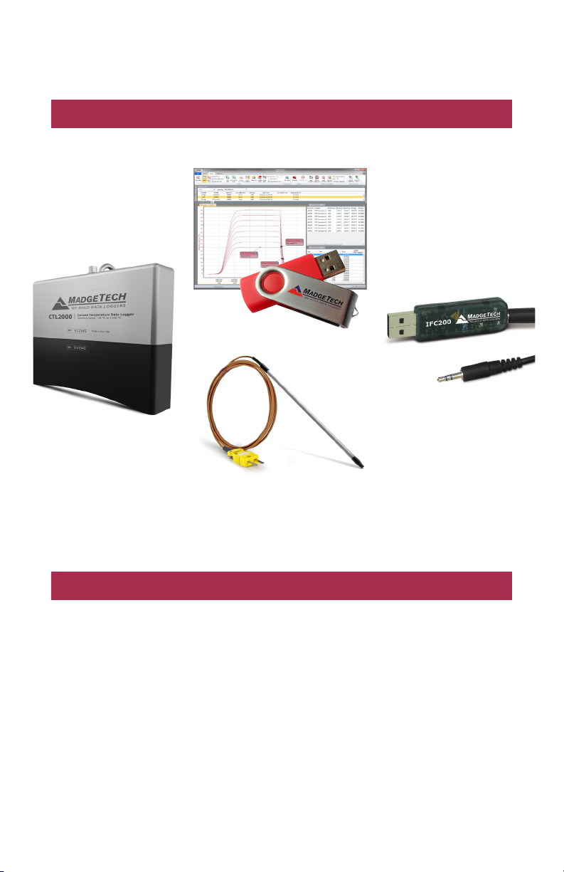
Complete System
CTL2000 Data Logger
MadgeTech 4 Software
Data Logger
Interface Device
& USB Cable
CTL2000
Type K Thermocouple
IFC200
Interface Cable
Quick Start Steps
Product Operation (Plugged In)
1. Install the MadgeTech 4 Software and USB Drivers onto a Windows PC.
2. The IFC200 interface device is a USB style interface; plug the USB portion of the
interface into an available USB port on the PC and plug the opposite end of the
cable into the communication port on the CTL2000.
3. Launch the MadgeTech 4 Software. The CTL2000 will appear in the connected devices
window indicating the device has been recognized.
4. Select the start method, reading rate and any other parameters appropriate for the
desired data logging application. Once configured, deploy the data logger by clicking
the Start icon.
5. To download data, select the device in the list, click the Stop icon, and then click the
Download icon. A graph will automatically display the data.
1
Page 4
Product User Guide
Product Overview
MadgeTech’s redesigned CTL2000 Carcass Temperature data logger is a rugged, one of a
kind solution for temperature monitoring during carcass pasteurization cycles. Equipped
with eight thermocouple ports, the CTL2000 monitors and records the temperatures
of various sections of the carcass during pasteurization, providing a continuous and
accurate temperature profile to verify and validate that harmful microorganisms are
effectively depleted.
The durable enclosure is drop tested and designed to survive the elements of the
slaughter environment. The top of the enclosure is made of food grade stainless steel
with an industrial quality custom machined base that skirts the thermocouple ports to
guard against debris infiltration and harsh wash down cycles. The quality materials and
form factor options were chosen using sanitary standards and guidelines, and made
with materials certified for direct food contact as described by NSF-51.
Measuring only eight inches in length and weighing only three pounds, the CTL2000 is
easy to handle and hangs securely from the carcass by a single stainless steel hook. This
device is capable of withstanding temperatures from -20 °C to 100 °C (-4 °F to +212 °F),
allowing it to monitor the entire pasteurization process.
Each channel of the CTL2000 can store up to 129,024 readings which aids in the
logging of multiples cycles. Reading rate capabilities range from as fast as four readings
per second or as infrequently as one reading every 24 hours. The CTL2000 operates on
user replaceable batteries and features a pushbutton start option directly on the device.
Delayed start is user programmable from within the MadgeTech Software for up to six
months in advance.
External Features
• Dimensions: 8.1 in x 6.5 in x 3.1 in (205 mm x 165 mm x 80 mm)
• Weight: 3.1 lb (49 oz)
• Enclosure & Hooks: 316 Stainless Steel
• Gasket Seal: EPDM rubber (NSF-51)
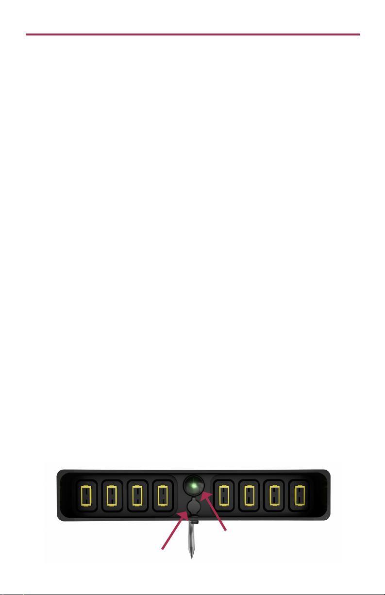
• Pushbutton Start: Located on the bottom of the data logger. (see below)
• 8 Thermocouple Ports (Compatible with type K only)
LED’s
Green LED:
• Blinks every 2 seconds to indicate unit is logging
• Blinks every 5 seconds to indicate unit is in delay start mode
Pushbutton Start
Interface Cable
Connection Port
2
Page 5

CTL2000
Additional Features and Operation
Password Settings
A password of a device that supports password capabilities can be set to protect it from
being altered by unauthorized users. If the device does not have password capabilities, no
password information will be displayed on the Device Properties screen.
To set the password of a device:
1. In the Connected devices panel, select the intended device to choose a password.
2. On the Device tab, in the Information group, click Properties. Users can also right-click
on the device and select Properties in the context menu.
3. On the General tab, click the Set password button.
4. Enter and confirm the password in the box that appears, and then click OK.
5. The software will display the message below when the password has been successfully
written.
3
Page 6

Product User Guide
Additional Features and Operation
Enable/Disable Channels
By default, all channels are enabled. To disable one or more channels follow the steps below.
To enable or disable a channel of a device:
1. In the Connected devices panel, select the intended device to enable/disable a channel.
2. On the Device tab, in the Information group, click Properties. Users can also right-click
on the device and select Properties in the context menu.
3. On the Channels tab, toggle Enable data recording on and off to enable or disable the
channel for the device.
4. Click Ok. Disabling channels increases the memory capacity of the enabled channels.
Changing the Channel Name of a Device
To change the channel name of a device:
1. In the Connected devices panel, select the intended device to change the name of the
thermocouple channel.
2. On the Device tab, in the Information group, click Properties. Users can also right-click
on the device and select Properties in the context menu.
3. On the Channel tab, click the Use custom name checkbox to change the name of
the thermocouple. (Note: Only the thermocouple channel name can be changed.) If there
is no option to use a custom name, the device does not have the option to rename a
thermocouple channel.
Profiling with Thermocouples
Eight thermocouples can be inserted into different sections of the carcass to provide an
overall temperature profile.
Photographs courtesy of JBS USA, LLC
Still need help?
For more troubleshooting tips and information, refer to the built in help section of the MadgeTech 4 software, visit
our Knowledge Base online at www.madgetech.com/kbase or contact us for customer support at 603-456-2011.
4
Page 7

CTL2000
Installation Guide
Installing the Interface Cable
Insert the IFC200 into a USB port. The drivers will install automatically. A blue light will
illuminate on the IFC200 indicating successful installation.
Installing the Software
Software can also be downloaded from the MadgeTech website at the following link: www.
madgetech.com/software-download. Follow the instructions provided in the Installation
Wizard.
Connecting and Starting the Data Logger
- Once the software is installed and running, plug the interface cable into the data logger.
- Connect the USB end of the interface cable into an open USB port on the computer.
- The device will appear in the Connected Devices list, highlight the desired data logger.
- For most applications*, select “Custom Start” from the menu bar and choose the desired
start method, reading rate and other parameters appropriate for the data logging
application and click “Start”. (“Quick Start” applies the most recent custom start options,
“Batch Start” is used for managing multiple loggers at once, “Real Time Start” stores the
dataset as it records while connected to the logger.)
- The status of the device will change to “Running”, “Waiting to Start” or “Waiting to
Manual Start”, depending upon your start method.
- Disconnect the data logger from the interface cable and place it in the environment to
measure. Note: The device will stop recording data when the end of memory is reached or the device is stopped. At this
point the device cannot be restarted until it has been re-armed by the computer.
*The CTL2000 also features a Pushbutton Start located at the base of the device which immediately activates the data logger
while in the field. The pushbutton does not stop the data logger from logging.
*Pushbutton Start
Manual Start
1. In the Connected devices panel, select the device. Confirm
that the intended device is highlighted.
2. On the Device tab, in the Control group, click Custom
Start. Users can also right-click on the device and select
Start, and then Custom Start in the context menu.
3. Under the Start method section within the Start device
screen, select the Manual radio button.
4. Choose any additional necessary start settings (such as reading interval, memory
wraparound, stop method, etc.).
5. Click the Start button. The Start device box will close and the status column in the
Connected devices panel will read, Waiting for manual start.
Downloading data from a Data Logger
- Connect the logger to the interface cable.
- Highlight the data logger in the Connected Devices list. Click “Stop” on the menu bar.
- Once the data logger is stopped, with the logger highlighted, click “Download”. You will
be prompted to name your report.
- Downloading will offload and save all the recorded data to the PC.
5
Page 8

Product User Guide
Product Maintenance
Recalibration
The CTL2000 standard calibration for the ambient channel are two points at 25 °C and
60 °C. The standard calibration for the thermocouple channel is one point at 0 mV.
MadgeTech recommends annual factory calibration, a reminder is automatically displayed
in the software when the device is due. Digital calibration within the software is also
available.
Call for custom calibration options to accommodate specific application needs.
Prices and specifications subject to change. See MadgeTech’s terms and conditions at www.madgetech.com
To send devices to MadgeTech for calibration, service or repair, please use the MadgeTech RMA Process (next section).
6
Page 9

CTL2000
RMA Instructions
To send a device back in to MadgeTech, follow the instructions below to create an RMA
(Return Merchandise Authorization) on the MadgeTech website:
1. Visit www.madgetech.com, under the Services tab select RMA Process.
2. When the web page opens, please sign in. If this is the first time, select Click here to
register an account and create one. Once signed in, click on the Make New RMA
button and fill in all the blank fields.
3. Complete the applicable fields on the form including customer Billing and Shipping
information, even if they are the same. Please see the field explanation below for a more
detailed description about questions asked in the Device Information section.
4. When all of the fields are complete, click Generate RMA.
5. Print out the confirmation page that follows containing the RMA number and
MadgeTech’s address for shipping. A Return Merchandise Authorization must be
accompanied by a copy of the RMA paperwork and shipping is prepaid by the
customer. The RMA number should be clearly marked on the outside of the package.
6. Please ship the package via UPS, FedEx, TNT, or DHL to the address listed on the
confirmation page. USPS will not ship MadgeTech data loggers.
7. A notification email will be automatically sent when MadgeTech has received the RMA.
7
Page 10

CTL2000 General Specifications
Reading Rate 4 readings per second up to 1 reading every 24 hours
Memory 129,024 readings per channel
LED Functionality:
Start Modes
Green LED:
• Blinks every 2 seconds to indicate unit is logging
• Blinks every 5 seconds to indicate unit is in delay start mode
Software programmable immediate start, pushbutton or delay start up
to six months in advance.
CTL2000
Password Protection
Memory Wrap
Around
Battery Type (2) 3.6V lithium battery included; user replaceable
Battery Life 4 years typical at a 5 minute reading rate
Calibration
Calibration Date Automatically recorded within the device
Data Format Date and time stamped ºC, ºF, K, ºR, mV, V
Time Accuracy ±1 minute/month
Computer Interface IFC200 USB (Interface cable required)
Operating System
Compatibility
MadgeTech Software
Compatibility
Operating
Environment
IP Rating IP67
An optional password may be programmed into the device to
restrict access to configuration options. Data may be read without
the password.
Yes
MadgeTech recommends annual factory calibration.
Digital calibration within the software is also available.
XP SP3/Vista/Windows 7/Windows 8
• Standard Software version 4.2.5.0 or later
• Secure Software version 4.2.4.0 or later
Continuous use: -20 °C to +100 °C (-4 °F to +212 °F)
0 %RH to 100 %RH
Dimensions 8.1 in x 6.5 in x 3.1 in (205 mm x 165 mm x 80 mm)
Weight 3.1 lb (49 oz)
Materials
• Enclosure & Hook: 316 Stainless Steel
• Gasket Seal: EPDM rubber (NSF-51)
8
Page 11

Temperature
8 Internal Channels
CTL2000
Internal Channel
Temperature Sensor
Temperature Range -20 °C to +100 °C (-4 °F to +212 °F)
Temperature Resolution 0.01 °C (0.018 °F)
Calibrated Accuracy ±0.5 °C (+10 °C to +80 °C)
Semiconductor
8 Remote Channels
Remote Channel
Temperature Sensor
Thermocouple
Connection Type
Cold Junction
Compensation
Thermocouple
Temperature Range
Temperature Resolution 0.1 °C (0.18 °F)
Calibrated Accuracy ±0.5 °C (±0.9 °F)
Compatible with Type K Only (Thermocouples sold separately)
Female Subminiature (SMP)
Automatic, based on internal channel
-270 °C to +1370 °C (-454 °F to +2498 °F)
Battery Warning
WARNING: FIRE, EXPLOSION AND SEVERE BURN HAZARD. DO NOT RECHARGE, DISASSEMBLE, HEAT ABOVE
100 °C (212 °F), INCINERATE, CRUSH, OR EXPOSE CONTENTS TO WATER.
See MadgeTech’s terms and conditions at www.madgetech.com
Specifications subject to change.
9
Page 12

Troubleshooting Tips
Why is the data logger not appearing in the software?
If the CTL2000 doesn’t appear in the Connected Devices panel, or an error message is displayed
while using the CTL2000, try the following:
• Ensure the Only show claimed wireless devices checkbox is unchecked.
• Check that the IFC200 is properly connected. For more information, see Troubleshooting Interface Cable
problems (below).
• Ensure that the battery is not discharged. For best voltage accuracy, use a voltage meter connected to
the battery of the device. If possible, try switching the battery with a new 7.2V lithium battery.
• Ensure that no other MadgeTech software (such as MadgeTech 2, or MadgeNET) is running.
• Ensure that MadgeTech 4 is being used. MadgeTech 2 and MadgeNET are not the correct software for
connecting with the CTL2000.
• Ensure that the Connected Devices panel is large enough to display devices. This can be verified by
positioning the cursor on the edge of the Connected Devices panel until the resize cursor appears, then
dragging the edge of the panel to resize it. The screen layout may also be reset in the options menu by
selecting File, Options, and scrolling to the bottom.
Troubleshooting Interface Cable problems
Check that the software properly recognizes the connected IFC200.
If the data logger is not appearing in the Connected Devices list, it may be that the IFC200 is not properly
connected.
1. In the software, click the File button, then click Options.
2. In the Options window, click Communications.
3. The Detected Interfaces box will list all of the available communication interfaces. If the IFC200 is listed
here, then the software has correctly recognized and is ready to use it.
Check that Windows recognizes the connected IFC200.
If the software does not recognize the IFC200, there may be a problem with Windows or the USB drivers.
1. In Windows, click Start, right-click Computer and choose Properties or press Windows+Break as a
keyboard shortcut.
2. Click Device Manager in the left hand column.
3. Double click Universal Serial Bus Controllers. Look for an entry for Data logger Interface.
5. If the entry is present, and there are no warning messages or icons, then windows has correctly
recognized the connected IFC200.
6. If the entry is not present, or has an exclamation point icon next to it, the USB drivers may need to
be installed. These are available on the software flash drive included with the IFC200, and on the
MadgeTech website.
Ensure that the USB end of the IFC200 is securely connected to the computer.
1. Locate the USB-A plug of your IFC200.
2. If the interface cable is connected to your PC, unplug it.
3. Wait ten seconds, then reinsert it.
4. The older versions of the IFC200 will have a red LED illuminate to signify that it has been connected
correctly. (The LED may also become unlit after flashing red.)
5. Newer IFC200s have different working LEDs.
a. The blue LED signifies that it is on and it is plugged into the computer correctly.
b. The amber LED signifies that it is busy. (Searching for devices when a device is not plugged in, starting,
stopping, downloading ect.)
c. The green LED signifies that the device has been successfully found, started, stopped, downloaded
ect. (The LED may also become unlit after flashing green.)
d. The red LED means the device has not been successfully found.
MadgeTech, Inc.
6 Warner Road
Phone 603.456.2011
www.madgetech.com
l
Warner, NH 03278
l
Fax 603.456.2012
l
info@madgetech.com
DOC 1203036-00 REV 3 2015.05.06
 Loading...