


W ireless LAN Security
Smart Wireless
Access Point 802.11b (95-10)
User Guide
100-408-01 Copyright © 2002 Madge Networks. All rights reserved. 20 Jul 2002

Federal Communication Commission Interference Statement
This equipment has been tested and found to comply with the limits for a Class B digital device, pursuant
to Part 15 of the FCC Rules. These limits are designed to provide reasonable protection against harmful
interference in a residential installation. This equipment generates, uses and can radiated radio frequency
energy and, if not installed and used in accordance with the instructions, may cause harmful interference
to radio communications. However, there is no guarantee that interference will not occur in a particular
installation. If this equipment does cause harmful interference to radio or television reception, which can
be determined by turning the equipment off and on, the user is encouraged to try to correct the
interference by one of the following measures:
Reorient or relocate the receiving antenna.
Increase the separation between the equipment and receiver.
Connect the equipment into an outlet on a circuit different from that to which the receiver is
connected.
Consult the dealer or an experienced radio/TV technician for help.
FCC Caution: To assure continued compliance, (example – use only shielded interface cables when
connecting to computer or peripheral devices). Any changes or modifications not expressly approved by
the party responsible for compliance could void the user’s authority to operate this equipment.
This transmitter must not be co-located or operating in conjunction with any other antenna or transmitter.
FCC Radiation Exposure Statement
This equipment complies with FCC radiation exposure limits set forth for an uncontrolled environment.
This equipment should be installed and operated with minimum distance 20 cm between the radiator &
your body.
This device complies with Part 15 of the FCC Rules. Operation is subject to the following two conditions:
(1) This device may not cause harmful interference, and (2) this device must accept any interference
received, including interference that may cause undesired operation.
100-408-01 Copyright © 2002 Madge Networks. All rights reserved. Page i

R&TTE Compliance Statement
This equipment complies with all the requirements of DIRECTIVE 1999/5/CE OF THE EUROPEAN
PARLIAMENT AND THE COUNCIL OF 9 March 1999 on radio equipment and telecommunication
terminal equipment and the mutual recognition of their conformity (R&TTE).
The R&TTE Directive repeals and replaces in the directive 98/13/EEC (Telecommunications Terminal
Equipment and Satellite Earth Station Equipment) as of April 8,2000.
Safety
This equipment is designed with the utmost care for the safety of those who install and use it. However,
special attention must be paid to the dangers of electric shock and static electricity when working with
electrical equipment. All guidelines of this and of the computer manufacture must therefore be allowed at
all times to ensure the safe use of the equipment.
EU Countries Intended for Use
The ETSI version of this device is intended for home and office use in Austria, Belgium, Denmark,
Finland, France (with Frequency channel restrictions), Germany, Greece, Ireland, Italy, Luxembourg,
Spain (with Frequency channel restrictions), Sweden, The Netherlands, and United Kingdom.
The ETSI version of this device is also authorized for use in EFTA member states Norway and
Switzerland.
EU Countries Not Intended for Use
Portugal.
Potential Restrictive Use
France: only channels 10, 11, 12, and 13.
Spain: only channels 10 and 11.
100-408-01 Copyright © 2002 Madge Networks. All rights reserved. Page ii

Contents
1 Introduction............................................................................................................................................ 1
1.1 Overview ........................................................................................................................................ 1
1.2 Features .......................................................................................................................................... 1
2 First-Time Installation and Configuration ............................................................................................. 2
2.1 Powering up the AP........................................................................................................................ 2
2.2 Mounting the AP on a Wall............................................................................................................ 2
2.3 Preparing for Configuration ........................................................................................................... 3
2.3.1 Connecting the Managing Computer and the Advanced AP .................................................. 3
2.3.2 Changing the TCP/IP Settings of the Managing Computer .................................................... 3
2.4 Configuring the Advanced AP ....................................................................................................... 4
2.4.1 Entering the User Name and Password ................................................................................... 4
2.4.2 Step 1: Configure TCP/IP Settings .........................................................................................5
2.4.3 Step 2: Configure IEEE 802.11 Settings................................................................................. 6
2.4.4 Step 3: Review and Apply Settings.........................................................................................6
2.5 Deploying the Advanced AP .......................................................................................................... 7
2.6 Setting up Client Computers .......................................................................................................... 7
2.6.1 Configuring IEEE 802.11b-Related Settings .......................................................................... 7
2.6.2 Configuring TCP/IP-Related Settings..................................................................................... 7
2.7 Confirming the Settings of the AP and Client Computers ............................................................. 7
2.7.1 Checking if the IEEE 802.11b-Related Settings Work ........................................................... 7
2.7.2 Checking if the TCP/IP-Related Settings Work ..................................................................... 8
3 Using the Web-Based Network Manager .............................................................................................. 9
3.1 Overview ........................................................................................................................................ 9
3.2 General Operations ....................................................................................................................... 11
3.2.1 Changing Password ............................................................................................................... 11
3.2.2 Upgrading Firmware ............................................................................................................. 11
3.3 Configuring TCP/IP Related Settings .......................................................................................... 12
3.3.1 Addressing ............................................................................................................................ 12
3.4 Configuring IEEE 802.11b-Related Settings ............................................................................... 13
3.4.1 Communication ..................................................................................................................... 13
3.4.2 Security ................................................................................................................................. 13
3.4.3 IEEE 802.1x/RADIUS .......................................................................................................... 14
3.5 Configuring Advanced Settings ................................................................................................... 16
3.5.1 Management .......................................................................................................................... 16
4 The Wireless Network Manager .......................................................................................................... 16
4.1 Installing the Wireless Network Manager .................................................................................... 16
4.2 Using the Wireless Network Manager ......................................................................................... 18
Appendix A ................................................................................................................................................. 20
A-1: Default Settings ............................................................................................................................... 20
A-2: LED Definitions .............................................................................................................................. 20
Appendix B: Troubleshooting..................................................................................................................... 21
B-1: Wireless Settings Problems ............................................................................................................. 21
B-2: TCP/IP Settings Problems ............................................................................................................... 21
B-3: Other Problems................................................................................................................................ 23
100-408-01 Copyright © 2002 Madge Networks. All rights reserved. Page iii

1 Introduction
1.1 Overview
The Madge advanced Smart Wireless Access Point (advanced AP) enables IEEE 802.11b client
computers to access the resources on an Ethernet network. Because it supports IEEE 802.1x and RADIUS
(Remote Authentication Dial-In User Service) for user-based authentication and dynamic encryption key
distribution, it is suitable for enterprises that need strong data security and WISPs (Wireless Internet
Service Providers) that need accounting and billing support.
In Section 2, we describe the steps to install and configure a newly acquired advanced AP. Following the
steps, the advanced AP can be quickly set up to work. In Section 3, detailed explanations of each Web
management page are given for the user to understand how to fine-tune the settings of an advanced AP to
meet his or her specific needs. In addition to using Web-based Network Manager to configure an
advanced AP, the Windows-based Wireless Network Manager can also be used to configure and monitor
advanced APs. See the on-line help of Wireless Network Manager for more information.
1.2 Features
Configuration Reset. Resetting the configuration settings to factory-default values.
IEEE 802.11b:
Management:
Access point. Bridging packets between the wireless IEEE 802.11b network interface and
the wired Ethernet LAN interface.
64-bit and 128-bit WEP (Wired Equivalent Privacy). For authentication and data encryption.
Enabling/disabling SSID broadcasts. The user can enable or disable the SSID (Service
Set ID) broadcast functionality for security reasons. When the SSID broadcast functionality is
disabled, a wireless client computer cannot connect to the advanced AP with a network name
(SSID) of “any”; the correct SSID has to be specified on client computers.
MAC-address-based access control. Blocking unauthorized wireless client computers
based on MAC (Media Access Control) addresses.
IEEE 802.1x/RADIUS. User authentication and dynamic encryption key distribution is
achieved by IEEE 802.1x Port-Based Network Access Control and RADIUS (Remote
Authentication Dial-In User Service).
Replaceable antennas. The factory-supplied antennas can be replaced with high-gain
antennas for different purposes. NOTE: High gain antennas must be used in accordance with
local regulatory rules.
Windows-based Wireless Network Manager for configuring, monitoring, and
diagnosing the local computer and neighboring advanced APs. The management protocol is
MAC-based.
Web-based Network Manager for configuring and monitoring advanced APs. The
management protocol is HTTP (HyperText Transfer Protocol)-based.
SNMP. SNMP (Simple Network Management Protocol) MIB I, MIB II, IEEE 802.1d, IEEE
802.1x and Enterprise MIB are supported.
UPnP. The advanced AP responds to UPnP discovery messages so that a Windows XP user
can locate the AP in My Network Places (the network neighborhood) and use a Web browser
to configure it.
100-408-01 Copyright © 2002 Madge Networks. All rights reserved. Page 1
Hardware Watchdog Timer. If the AP firmware enters an invalid state, the hardware watchdog
timer will detect this situation and restart the advanced AP. Accordingly, the advanced AP can
recover from certain error situations.
2 First-Time Installation and Configuration
2.1 Powering up the AP
To power the AP with the supplied power adapter:
1. Plug the power adapter to an AC socket.
2. Plug the connector of the power adapter to the power jack of the AP.
NOTE: This product is intended to be powered by a Listed Power Unit, marked “Class 2” or “LPS” and
output rated “5V DC, 1 A minimum” or equivalent statement.
Some advanced APs support Power Over Ethernet (POE). Visit the Madge web-site at www.madge.com
for more details.
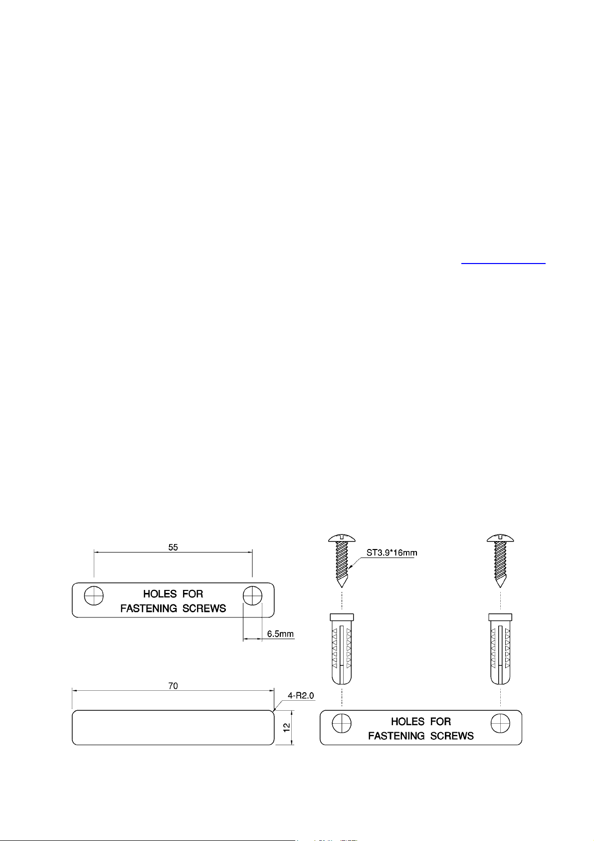
2.2 Mounting the AP on a Wall
If required the AP can be mounted on a wall.
CAUTION: Before drilling into any surface check for hidden services such as electricity cables or water
pipes. If in doubt please consult a qualified engineer.
NOTE: The fastenings supplied with this product are intended for use in solid walls only.
To fix the AP to a solid wall proceed as follows:
1. Use the supplied template to determine the correct distance between the fastening screws.
2. Use a 6.5mm diameter drill to make a 25mm deep hole at each of the cross marks.
3. Insert the supplied “wall-plugs” into each hole.
4. Insert the supplied screws into the wall-plugs leaving approximately 3mm of thread proud of the
wall surface to allow the AP to be hung on the screws.
5. Hang the wireless AP on the screws.
Fig. 1. Mounting the AP on a wall.
100-408-01 Copyright © 2002 Madge Networks. All rights reserved. Page 2
2.3 Preparing for Configuration
For the user (or administrator) to configure an advanced AP, a managing computer with a Web browser is
needed. For first-time configuration of an advanced AP, an Ethernet network interface card (NIC) should
have been installed in the managing computer. For maintenance-configuration of a deployed advanced
AP, either a wireless computer or a wired computer can be employed as the managing computer.
NOTE: If you are using the browser, Opera, to configure an advanced AP, click the menu item File, click
Preferences..., click File types, and edit the MIME type, text/html, to add a file extension ".sht" so that
Opera can work properly with the Web management pages of the advanced AP.
Since the configuration/management protocol is HTTP-based, we have to make sure that the IP address
of the managing computer and the IP address of the managed advanced AP are in the same IP
subnet (the default IP address of an AP is 192.168.0.1 and the default subnet mask is 255.255.255.0.)
NOTE: The AP’s factory default setting is to obtain its IP address automatically from a DHCP Server.
When the AP restarts it attempts to obtain an IP address repeatedly for approximately 75 seconds. If this
fails then it adopts the default IP address of 192.168.0.1.
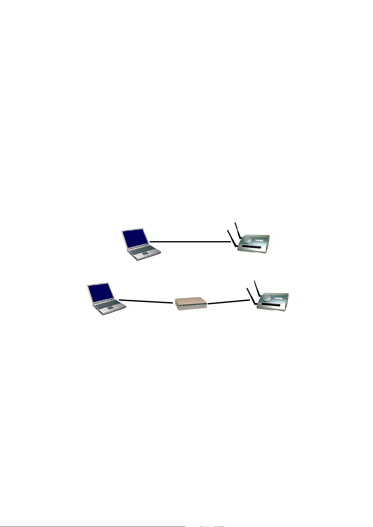
2.3.1 Connecting the Managing Computer and the Advanced AP
To connect the Ethernet managing computer and the managed AP for first-time configuration, the user
has two choices as illustrated in Fig. 2.
Cross-over
Ethernet
cable
Managing
Computer
Normal
Ethernet
cable
Ethernet
Hub/Switch
Normal
Ethernet
cable
Managed
AP
Fig. 2. Connecting a managing computer and an advanced AP via Ethernet.
The user can use either a cross-over Ethernet cable (we have included one in the package) or a switch/hub
with 2 normal Ethernet cables.
NOTE: One connector of the Ethernet cable must be plugged into the LAN/Config Ethernet socket of the
advanced AP for configuration.
2.3.2 Changing the TCP/IP Settings of the Managing Computer
Use the Windows Network Control Panel Applet to change the TCP/IP settings of the managing
computer, so that the IP address of the computer and the IP address of the advanced AP are in the same IP
subnet. Set the IP address of the computer to 192.168.0.xxx (the default IP address of an AP is
192.168.0.1) and the subnet mask to 255.255.255.0.
NOTE: For some versions of Windows, the computer needs to be restarted for the changes of TCP/IP
settings to take effect.
100-408-01 Copyright © 2002 Madge Networks. All rights reserved. Page 3
2.4 Configuring the Advanced AP
After the IP addressing issue is resolved, launch a Web browser on the managing computer. Then, go to
“http://192.168.0.1” to access the Web-based Network Manager start page.
TIP: For maintenance configuration of an advanced AP, the advanced AP can be reached by its host
name using a Web browser. For example, if the advanced AP is named “advanced AP”, you can use the
URL “http://advanced AP” to access the Web-based Network Manager of the advanced AP.
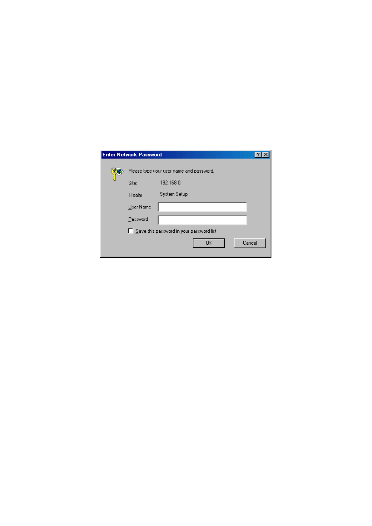
2.4.1 Entering the User Name and Password
Before the start page is shown, you will be prompted to enter the user name and password to gain the
right to access the Web-based Network Manager. For first-time configuration, use the default user name
“root” and default password “root”, respectively.
Fig. 3. Entering the user name and password.
NOTE: It is strongly recommended that the password be changed to other value for security reasons. On
the start page, click the General\Password link to change the value of the password (see Section 3.2.1 for
more information).
TIP: Since the start page shows the current settings and status of the advanced AP, it can be saved or
printed within the Web browser for future reference.
100-408-01 Copyright © 2002 Madge Networks. All rights reserved. Page 4
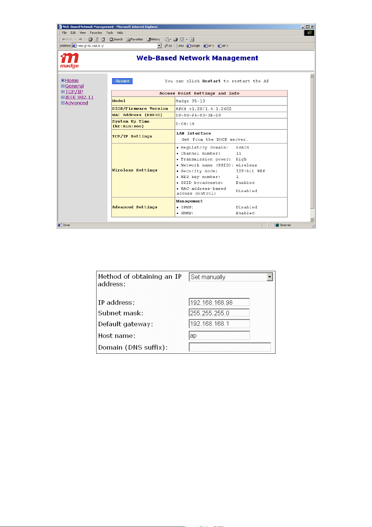
Fig. 4. The Start page.
2.4.2 Step 1: Configure TCP/IP Settings
Fig. 5. TCP/IP settings.
Go to the TCP/IP, Addressing section to configure IP address settings. The IP address can be manually
set or automatically assigned by a DHCP server on the LAN. If you are manually setting the IP Address,
Subnet Mask, and Default Gateway settings, set them appropriately, so that they comply with your LAN
environment. In addition, you can specify the Host Name and Domain (DNS suffix) of the advanced AP.
When you are finished, click Save at the bottom of this page, and then you are brought back to the start
page.
100-408-01 Copyright © 2002 Madge Networks. All rights reserved. Page 5

2.4.3 Step 2: Configure IEEE 802.11 Settings
Fig. 6. IEEE 802.11b communication settings.
Go to the IEEE 802.11, Communication section to configure IEEE 802.11b-related communication
settings, including Regulatory Domain, Channel Number, and Network Name (SSID).
The number of available RF channels depends on local regulations; therefore you have to choose an
appropriate regulatory domain to comply with local regulations. The SSID of a wireless client computer
and the SSID of the advanced AP must be identical for them to communicate with each other.
When you are finished, click Save at the bottom of this page, and then you are brought back to the start
page.
NOTE: The factory default setting for the Regulatory Domain is “Spain”. This is because in Spain only
channels 10 and 11 are authorised for use. Thus an AP “out of the box” will only transmit on channels 10
and 11 and this ensures compliance with international regulations. When the default Regulatory domain
is changed the AP will use an expanded set of channels.
2.4.4 Step 3: Review and Apply Settings
Fig. 7. Settings changes are highlighted in red.
100-408-01 Copyright © 2002 Madge Networks. All rights reserved. Page 6

On the start page, you can review all the settings you have made. Changes are highlighted in red. If they
are OK, click Restart to restart the advanced AP for the new settings to take effect.
NOTE: About 7 seconds are needed for the advanced AP to complete its restart process.
2.5 Deploying the Advanced AP
After the settings have been configured, deploy the advanced AP to the field application environment.
Connect Ethernet client computers to the Ethernet switch ports of the advanced AP.
2.6 Setting up Client Computers
The TCP/IP and IEEE 802.11b-related settings of wireless client computers must match those of the
advanced AP.
2.6.1 Configuring IEEE 802.11b-Related Settings
Before the TCP/IP networking system of a wireless client computer can communicate with other hosts,
the underlying wireless link must be established between this wireless computer and an advanced AP.
To establish a wireless link to an advanced AP:
1. Launch the configuration/monitoring utility provided by the vendor of the installed WLAN NIC.
2. Use the utility to make appropriate Operating Mode, SSID and WEP settings.
NOTE: A client must be in infrastructure mode, so that it can link to an AP.
NOTE: The SSID of the wireless client computer and the SSID of the advanced AP must be identical. Or,
in case the SSID broadcasts capability of the advanced AP is enabled (by default), the SSID of the
wireless client computer could be set to “any”.
NOTE: Both the wireless client computer and the advanced AP must have the same WEP settings for
them to communicate with each other.
2.6.2 Configuring TCP/IP-Related Settings
Use Windows Network Control Panel Applet to change the TCP/IP settings of the client computers, so
that the IP addresses of the client computers and the IP address of the advanced AP are in the same IP
subnet.
If a client computer is originally set a static IP address, the user can either change its IP address to match
the IP address of the AP, or select an automatically-obtain-an-IP-address option if there is a DHCP server
on the network.
NOTE: For some versions of Windows, the computer needs to be restarted for the changes of TCP/IP
settings to take effect..
2.7 Confirming the Settings of the AP and Client Computers
After you have completed deploying the advanced AP and setting up client computers, you have to make
sure the settings you have made are correct.
2.7.1 Checking if the IEEE 802.11b-Related Settings Work
To check if a wireless client computer can link to the advanced AP:
100-408-01 Copyright © 2002 Madge Networks. All rights reserved. Page 7

1. Launch the configuration/monitoring utility provided by the vendor of the installed WLAN NIC.
2. Check if the client computer is associated to an access point, and the access point is the advanced AP.
If the check fails, see Appendix B-1, “Wireless Settings Problems” for troubleshooting.
2.7.2 Checking if the TCP/IP-Related Settings Work
To check if a client computer can access the Internet:
1. Open a Windows Command Prompt window on the client computer.
2. Type “ping advap”, where advap is a placeholder for the IP address of the advanced AP. Replace it
with your real IP address—for example, 192.168.0.1. Then press Enter.
If the advanced AP responds, go to the next step; else, see Appendix B-2, “TCP/IP Settings
Problems” for troubleshooting.
3. Type “ping default_gateway”, where default_gateway is a placeholder for the IP address of the
default gateway of the wireless client computer. Then press Enter.
If the gateway responds, go to the next step; else, see Appendix B-2, “TCP/IP Settings Problems”
for troubleshooting.
4. Type “ping 1st_dns_server”, where 1st_dns_server is a placeholder for the IP address of the primary
DNS server of the wireless client computer. Then press Enter.
If this DNS server responds, go to the next step; else, see Appendix B-2, “TCP/IP Settings
Problems” for troubleshooting.
5. Type “ping 2nd_dns_server”, where 2nd_dns_server is a placeholder for the IP address of the
secondary DNS server of the wireless client computer. Then press Enter.
If this DNS server responds the client should have no problem with TCP/IP networking; else, see
Appendix B-2, “TCP/IP Settings Problems” for troubleshooting.
100-408-01 Copyright © 2002 Madge Networks. All rights reserved. Page 8

3 Using the Web-Based Network Manager
This section explains each management page of the Web-based Network Manager.
3.1 Overview
Fig. 8. The Start page.
The left side of the start page contains a menu for the user to carry out commands. Here is a brief
description of the hyperlinks in the menu:
Home. For going back to the start page.
General. Global operations.
Password. For gaining right to change the settings of the advanced AP.
Firmware Upgrade. For upgrading the firmware of the advanced AP.
TCP/IP. TCP/IP-related settings.
Addressing. IP addressing settings for the advanced AP to work in the TCP/IP networking
world.
IEEE 802.11. IEEE 802.11b-related settings.
Communications. Basic settings for the IEEE 802.11b interface of the advanced AP to
work properly with wireless clients.
Security. Security settings for authenticating wireless users and encrypting wireless data.
IEEE 802.1x/RADIUS (Advanced model). IEEE 802.1x Port-Based Network Access
Control and RADIUS (Remote Authentication Dial-In User Service) settings for better
wireless security.
100-408-01 Copyright © 2002 Madge Networks. All rights reserved. Page 9

Advanced. Advanced settings of the advanced AP.
Management. UPnP and SNMP settings.
Fig. 9. Save, Save & Restart, and Cancel.
At the bottom of each page, there are up to three buttons—Save, Save & Restart, and Cancel. Clicking
Save stores the settings changes to the memory of the advanced AP and brings the user back to the start
page. Clicking Save& Restart stores the settings changes to the memory of the advanced AP and restarts
the advanced AP immediately for the settings changes to take effect. Clicking Cancel discards any
settings changes and brings the user back to the start page.
If the user clicks Save, the start page will reflect the fact that the configuration settings have been
changed by showing two buttons—Restart and Cancel. In addition, changes are highlighted in red.
Clicking Cancel discards all the changes. Clicking Restart restarts the advanced AP for the settings
changes to take effect.
Fig. 10. Settings have been changed.
100-408-01 Copyright © 2002 Madge Networks. All rights reserved. Page 10

3.2 General Operations
3.2.1 Changing Password
Fig. 11. Password.
On this page, the user could change the password for the right to modify the configuration of the
advanced AP. The new password must be typed twice for confirmation.
3.2.2 Upgrading Firmware
Fig. 12. Firmware Upgrade.
The advanced AP can be triggered to download updated firmware from a specified TFTP server. On this
page, the user specifies the IP address of the intended TFTP server, and then triggers the advanced AP to
begin downloading.
Within the folder “AP\Utilities” on the companion CD-ROM disk, there is a TFTP server program
(TftpSrvr.exe) for firmware upgrade. Run this program on the computer that is to serve as a TFTP server.
To upgrade the firmware of advanced AP:
1. Get a computer that will be used both as a TFTP server and as a managing computer to trigger the
upgrade process.
2. Connect the computer and the AP’s LAN/Config Ethernet port with a crossover Ethernet cable.
3. Configure the computer with a static IP address that is compatible with the IP address of the AP.
4. On the computer, run the TFTP Server utility. And specify the folder in which the firmware files
reside.
5. On the computer, run a Web browser and connect to the AP. On the AP’s Home Page click the
General/Firmware Upgrade hyperlink.
6. Specify the IP address of the computer, which acts as a TFTP server. If you don't know the IP
address of the computer, open a Command Prompt, and type IpConfig, then press the Enter key.
7. Trigger the firmware upgrade process by clicking Upgrade.
100-408-01 Copyright © 2002 Madge Networks. All rights reserved. Page 11

Fig. 13. TFTP Server.
TIP: It's more convenient to use the Firmware Upgrade Wizard of Wireless Network Manager to upgrade
the firmware of an advanced AP. See section 4.
NOTE: After the dialog box of the TFTP server program appears, be sure to specify the working folder
within which the downloaded firmware files reside.
NOTE: The LAN IP address of the advanced AP and the IP address of the TFTP server must be in the
same IP subnet for TFTP to work.
NOTE: Due to the nature of wireless media, it’s highly recommended that the TFTP server and the to-be-
upgraded advanced AP be connected by Ethernet, and on the same LAN, so that the upgrade process will
be smooth.
NOTE: After the firmware is upgraded, be sure to delete the contents of the Web browser cache, so that
the Web management pages can be shown correctly.
NOTE: A failed upgrade may corrupt the firmware and make the advanced AP unstartable. When this
occurs, call technical support.
3.3 Configuring TCP/IP Related Settings
3.3.1 Addressing
Fig. 14. TCP/IP settings.
100-408-01 Copyright © 2002 Madge Networks. All rights reserved. Page 12

The IP address of the AP can be manually set or automatically assigned by a DHCP server on the LAN. If
you are manually setting the IP Address, Subnet Mask, and Default Gateway settings, set them
appropriately, so that they comply with your LAN environment. In addition, you can specify the Host
Name and Domain (DNS suffix) of the AP.
3.4 Configuring IEEE 802.11b-Related Settings
3.4.1 Communication
IEEE 802.11b-related communication settings include Regulatory Domain, Channel Number, and
Network Name (SSID).
Fig. 15. IEEE 802.11b communication settings.
The number of available RF channels depends on local regulations; therefore you have to choose an
appropriate regulatory domain to comply with local regulations. The SSID of a wireless client computer
and the SSID of the advanced AP must be identical for them to communicate with each other.
3.4.2 Security
Fig. 16. IEEE 802.11b communication settings.
IEEE 802.11b security settings include SSID Broadcasts, Security Mode, WEP Keys, MAC-Address-
Based Access Control.
For security reasons, it’s highly recommended that the security mode be set to options other than Open
System. When the security mode is set to Open System, no authentication and data encryption will be
performed. Additionally, you can disable the SSID broadcasts functionality so that a wireless client
computer with an “any” SSID cannot connect to the advanced AP.
There are 9 security modes:
Open System. No authentication, no data encryption.
64-bit WEP. Authentication and data encryption based on 64-bit WEP (Wired Equivalent Privacy).
128-bit WEP. Authentication and data encryption based on 128-bit WEP (Wired Equivalent
Privacy), and 128-bit keys are used.
100-408-01 Copyright © 2002 Madge Networks. All rights reserved. Page 13

802.1x EAP-MD5. The IEEE 802.1x functionality is enabled and the username/password-based
EAP-MD5 authentication is used. No data encryption.
802.1x EAP-MD5 + 64-bit WEP. The IEEE 802.1x functionality is enabled and the
username/password-based EAP-MD5 authentication is used. Data encryption is achieved by 64-bit
WEP.
802.1x EAP-MD5 + 128-bit WEP. The IEEE 802.1x functionality is enabled and the
username/password-based EAP-MD5 authentication is used. Data encryption is achieved by 128-bit
WEP.
802.1x EAP-TLS; no encryption. The IEEE 802.1x functionality is enabled and the digital
certificate-based EAP-TLS user authentication. No data encryption is used.
802.1x EAP-TLS 64-bit key. The IEEE 802.1x functionality is enabled and the digital certificate-
based EAP-TLS (Transport Layer Security) user authentication and data encryption is used. Session
keys are 64-bit.
802.1x EAP-TLS 128-bit key. The IEEE 802.1x functionality is enabled and the digital
certificate-based EAP-TLS user authentication and data encryption is used. Session keys are 128-bit.
See Section 3.4.3 for more information about IEEE 802.1x.
With MAC-Address-Based Access Control, you can specify the wireless client computers that are
permitted or not permitted to connect to the advanced AP. When the table type is set to inclusive, entries
in the table are permitted to connect to the advanced AP. When the table type is set to exclusive, entries
in the table are not permitted to connect to the advanced AP.
To deny wireless clients’ access to the wireless network:
1. Select Enabled from the Functionality drop-down list.
2. Set the Access control type to exclusive.
3. Specify the MAC address of a wireless client to be denied access, and then click Add.
4. Repeat Steps 3 for other wireless clients.
To grant wireless clients’ access to the wireless network:
1. Select Enabled from the Functionality drop-down list.
2. Set the Access control type to inclusive.
3. Specify the MAC address of a wireless client to be granted access, and then click Add.
4. Repeat Steps 3 for other wireless clients.
To delete an entry in access control table:
Click Delete next to the entry.
3.4.3 IEEE 802.1x/RADIUS
IEEE 802.1x Port-Based Network Access Control is a new standard for solving some security issues
associated with IEEE 802.11, such as lack of user-based authentication and dynamic encryption key
distribution. With IEEE 802.1x and the help of a RADIUS (Remote Authentication Dial-In User Service)
server and a user account database, an enterprise or ISP (Internet Service Provider) can manage its mobile
users' access to its wireless LANs. Before granted access to a wireless LAN supporting IEEE 802.1x, a
user has to issue his or her user name and password or digital certificate to the backend RADIUS server
by EAPOL (Extensible Authentication Protocol Over LAN). The RADIUS server can record accounting
information such as when a user logs on to the wireless LAN and logs off from the wireless LAN for
monitoring or billing purposes.
100-408-01 Copyright © 2002 Madge Networks. All rights reserved. Page 14

The IEEE 802.1x functionality of the advanced AP is controlled by the security mode (see Section 3.4.2).
The advanced AP supports two authentication mechanisms—EAP-MD5 (Message Digest version 5) and
EAP-TLS (Transport Layer Security). If EAP-MD5 is used, the user has to give his or her user name and
password for authentication. If EAP-TLS is used, the wireless client computer automatically gives the
user’s digital certificate that is stored in the computer hard disk or a smart card for authentication. And
after a successful EAP-TLS authentication, a session key is automatically generated for wireless packets
encryption between the wireless client computer and its associated advanced wireless access point. To
sum up, EAP-MD5 supports user authentication, while EAP-TLS supports user authentication as well as
dynamic encryption key distribution.
Fig. 17. IEEE 802.1x and RADIUS.
An advanced AP supporting IEEE 802.1x can be configured to communicate with two RADIUS servers.
When the primary RADIUS server fails to respond, the advanced wireless access point will try to
communicate with the secondary RADIUS server. The user can specify the length of timeout and the
number of retries before communicating with the secondary RADIUS server after failing to communicate
with the primary RADIUS server.
An IEEE 802.1x-capable advanced wireless access point and its RADIUS server(s) share a secret key so
that they can authenticate each other. In addition to its IP address, an advanced wireless access point can
identify itself by an NAS (Network Access Server) identifier. Each IEEE 802.1x-capable advanced
wireless access point must have a unique NAS identifier.
Fig. 18. IEEE 802.1x/RADIUS settings.
100-408-01 Copyright © 2002 Madge Networks. All rights reserved. Page 15

3.5 Configuring Advanced Settings
3.5.1 Management
3.5.1.1 SNMP
Fig. 19. SNMP settings.
The AP can be managed by SNMP (Simple Network Management Protocol), and the SNMP management
functionality can be disabled. The user can specify the name (used as a password) of the read-only and
read-write community. In addition, up to 5 SNMP trap targets can be set in the SNMP Trap table.
3.5.1.2 UPnP
Fig. 20. UPnP settings.
UPnP (Universal Plug and Play) enables a Windows XP user to automatically discover peripheral devices
by HTTP. When the UPnP functionality is enabled, the user can see the AP in My Network Places (the
Network Neighborhood) of Windows XP. The AP can be given a friendly name that will be shown in
My Network Places. Double-clicking the icon in My Network Places that stands for the AP will launch
the default Web browser for the user to configure the AP.
4 The Wireless Network Manager
The CD-ROM that accompanies the Advanced AP includes a program called the Wireless Network
Manager. This program is compatible with Windows 98/Me/2000/XP.
NOTE: Under Windows 2000 or XP the program must be run by an Administrator.
4.1 Installing the Wireless Network Manager
1. Insert the accompanying CD-ROM into your CD-ROM drive.
100-408-01 Copyright © 2002 Madge Networks. All rights reserved. Page 16

2. If AutoPlay is enabled then the “Accept Warranty Dialog” should appear (if not, it can be run from
D:\Setup.exe where D: is the drive letter of your CD-ROM). Read the agreement and click Accept if
you agree to the terms of the Warranty. The following dialog will appear:
Fig. 21. Setup top-level menu.
3. Click Install utilities and drivers, the following dialog will appear:
Fig. 22. Utilities and drivers menu.
4. Click on Install Wireless Network Manager for Access Point 802.11b (95-10) to install the utility.
5. Follow the instructions of the Installer Wizard to complete the installation of the Wireless Network
Manager.
6. Alternatively you can run “D:\AP\WNM\Setup.exe” (where D: is the drive letter of your CD-ROM;
replace it with a correct letter if necessary) to install the Wireless Network Manager.
100-408-01 Copyright © 2002 Madge Networks. All rights reserved. Page 17

4.2 Using the Wireless Network Manager
When the Installer Wizard is complete the Wireless Network Manager program will be available in the
Programs section of your Windows Start menu.
The first time the Wireless Network Manager runs it presents the Wireless Configuration Wizard that
will help you make the appropriate settings for the various elements of your wireless system.
Fig. 23. The Wireless Configuration Wizard.
Follow the instructions of the wizard.
NOTE: The Wireless Configuration Wizard can discover any locally attached Access Points. If you
select a discovered AP for re-configuration, and enter the AP’s valid password, it will be reset (even if
you do not actually make any changes to its configuration).
NOTE: The default password for an AP is “root”. See Appendix A-1 for other AP default settings.
NOTE: The Wireless Configuration Wizard will be redisplayed every time that the Wireless Network
Manager is run until it successfully completes the particular configuration that is requested.
Once the Wireless Configuration Wizard has finished the Wireless Network Manager program will
run. Initially the Wireless Network Manager is shown “minimised” as a yellow icon in the system tray
of the Windows task bar.
Fig. 24. The Wireless Network Manager in the system tray.
Double click the icon to open the program; the Wireless Network Manager will then show a window
similar to the following:
100-408-01 Copyright © 2002 Madge Networks. All rights reserved. Page 18

Fig. 25. Typical Wireless Network Manager dialog.
Use the On-line help to guide you through the features and functions of the Wireless Network Manager.
All the features of the Web-based Network Manager (see section 3) are available using the Wireless
Network Manager, and more.
100-408-01 Copyright © 2002 Madge Networks. All rights reserved. Page 19

Appendix A
A-1: Default Settings
TIP: Press the Default (SF-Reset, or Soft-Reset) switch on the housing of a powered-on advanced AP to
reset the configuration settings to factory-default values.
Global
User Name root
Password root
Host Name “M95-10xxxxxx” where xxxxxx = last 6 hex digits
IEEE 802.11b
Regulatory Domain Spain
Channel Number 11
SSID wireless
SSID Broadcasts Enabled
Transmission Rate 11Mbps
Transmission Power High
MAC Address See the label on the housing of the advanced AP.
Security Mode 128-bit WEP
Selected WEP Key Key #1
WEP Key #1 Generated by using Host Name as the passphrase
WEP Key #2 00-00-00-00-00-00-00-00-00-00-00-00-00
WEP Key #3 00-00-00-00-00-00-00-00-00-00-00-00-00
WEP Key #4 00-00-00-00-00-00-00-00-00-00-00-00-00
MAC-Address-Based Access
Access Control Table Type Inclusive
LAN Interface
Method of obtaining an IP
IP Address 192.168.0.1
Subnet Mask 255.255.255.0
Default Gateway 0.0.0.0
Management
SNMP Enabled
SNMP read community public
SNMP write community private
UPnP Disabled
Setting Name Default Value
of the AP's MAC address
Disabled
Control
Obtain automatically by DHCP.
Address
If the AP fails to obtain an IP address from a
DHCP server after 75 seconds, it assigns
192.168.0.1 as its IP address.
A-2: LED Definitions
There are several LED indicators on the housing of an advanced AP. They are defined as follows:
ALV: Alive. Blinks when the advanced AP is working normally.
RF: Activity on the IEEE 802.11b interface.
LAN: Activity on the Ethernet LAN interface.
PWR: Power is applied.
100-408-01 Copyright © 2002 Madge Networks. All rights reserved. Page 20

Appendix B: Troubleshooting
Check the following first:
Make sure that the power of the advanced AP is on and the Ethernet cables are connected firmly to
the RJ-45 jacks of the advanced AP.
Make sure that the LED ALV of the advanced AP is blinking to indicate the advanced AP is
working.
Make sure the types of the Ethernet cables are correct. Recall that there are two types—normal and
crossover.
B-1: Wireless Settings Problems
The wireless client computer cannot link to an access point.
Is the wireless client set in infrastructure mode?
Check the operating mode of the WLAN NIC.
Is the SSID of the WLAN NIC identical to that of the prospective access point or advanced
AP?
Check the SSID setting of the WLAN NIC and of the advanced AP.
Is the WEP functionality of the prospective access point or advanced AP enabled?
Make appropriate WEP settings of the client computer to match those of the access point
or advanced AP.
Is the prospective access point or advanced AP within range of wireless communication?
Check the signal strength and link quality sensed by the WLAN NIC.
B-2: TCP/IP Settings Problems
IEEE 802.11b
Ethernet LAN
Correspondent
Host
Internet
Client
Computer
Stage A State B
Advanced
AP
Default Gateway
of Client Computer
Stage D
DNS Server
of Client Computer
Fig. 26. Communication stages for a client to reach its correspondent host.
100-408-01 Copyright © 2002 Madge Networks. All rights reserved. Page 21

For a wireless client computer to communicate with a correspondent host on the Internet by the host’s
domain name (e.g. http://www.madge.com
), it first sends a DNS request to a DNS server on the Internet.
The DNS request travels first to the advanced AP, the advanced AP then relays this request to the default
gateway of the client computer. Finally, this request is forwarded by the gateway to the DNS server on
the Internet. The DNS reply issued by the DNS server is transmitted back to the client computer
following a reverse path. When the client computer receives the DNS reply, it knows the IP address of the
correspondent host and sends further packets to this IP address.
As illustrated in Fig. 26, the communication path could be broken at some of the stages. The OS-provided
network diagnostic tool, ping.exe, can be employed to find out TCP/IP-related communication problems.
NOTE: If two or more NICs are installed and operating on a client computer, TCP/IP may not work
properly due to incorrect entries in the routing table. Use the OS-provided command-line network tool,
route.exe, to add or delete entries from the routing table. Or, use Windows-provided Device Manager to
disable unnecessary NICs.
Solve the following problems in order:
The advanced AP does not respond to ping from the client computer.
Are two or more NICs installed on the client computer?
Use the OS-provided command-line network tool, route.exe, to modify the contents of
the routing table.
Use Windows-provided Device Manager to disable unnecessary NICs.
Is the underlying link (Ethernet or IEEE 802.11b) established?
Make sure the Ethernet link is OK.
Make sure the wireless settings of the wireless client computer and of the advanced AP
match.
Are the IP address of the client computer and the IP address of the advanced AP in the same
IP subnet?
Use WinIPCfg.exe or IPConfig.exe to see the current IP address of the client computer.
Make sure the IP address of the client computer and the IP address of the advanced AP
are in the same IP subnet.
TIP: If you forget the current IP address of the advanced AP, use Wireless Router/AP
Browser to get the information (see Appendix B-3).
The default gateway of the client computer does not respond to ping from the client computer.
Solve the preceding problem first.
Are the IP address of the advanced AP and the IP address of the client computer in the same
IP subnet?
If you cannot find any incorrect settings of the advanced AP, the default gateway may be
really down or there are other communication problems on the network backbone.
The DNS server(s) of the client computer do not respond to ping from the client computer.
Solve the preceding problems first.
If you cannot find any incorrect settings of the advanced AP, the default gateway of the
advanced AP may be really down or there are other communication problems on the network
backbone.
100-408-01 Copyright © 2002 Madge Networks. All rights reserved. Page 22

B-3: Other Problems
The AP has been set to obtain an IP address automatically by DHCP. How can I know its acquired
IP address so that I can manage it using a Web browser?
Use the utility, Wireless Router/AP Browser (WLBrwsr.exe), in the “AP\Utilities” folder on
the companion CD-ROM disc. This utility can discover nearby advanced APs and show their
MAC addresses and IP addresses. In addition, it can launch the default Web browser on your
computer.
Fig. 27. Wireless Router/AP Browser.
The advanced AP stops working and does not respond to Web management requests.
The firmware of the advanced AP may be stuck in an incorrect state.
Unplug the power connector from the power jack, and then re-plug the connector to
restart the advanced AP.
If the advanced AP still does not work after restarting, there may be hardware component
failures in the advanced AP.
Contact technical support for repair if the unit is in Warranty. Visit www.madge.com/support
details.
for more
100-408-01 Copyright © 2002 Madge Networks. All rights reserved. Page 23
 Loading...