

Made Gas Tracker 2 User Manual

M A D E
S.A. au capital de 270 130 €
167, Impasse de la garrigue
F 83210 LA FARLEDE
Tél. : +33 (0) 494 083 198 - Fax : +33 (0) 494 082 879
E-mail : contact@made-sa.com - Web : www.made-sa.com
Gas Tracker 2
User Guide
FQ_47_V_1.00 du 22.12.2015

gu_gas_tracker2_v_2_15_en
2 / 35
RÉPERT OIR E D E S M O D I F IC ATIONS
Rév. Objet des modifications
Date et Auteur
1.00
1.10
2.00
2.01
2.10 FR
2.10 EN
2.11 EN
2.12 EN
2.13 EN
2.13 EN
2.15 EN
CRÉATION
Corrections mineures
Refonte manuel et rajout cas pratiques
Ajout notes de sécurité électrique
Corrections mineures / terminologie
English translation
Added tech. Details §8
Added the use of tablet
Minor corrections
Added location and log information
Added location and log information
2011 Ph. Coste
2015 Ph. Picon
12/2016 Ph.Picon
01/2016 Ph Coste
01/2016 Ph. Picon
01/2016 Ph. Picon
09/2017 Ph.Picon
03/2018 L. Zomero
12/2018 Ph.Picon
12/2018 L. Zomero
02/2019 P.Picon

gu_gas_tracker2_v_2_15_en
3 / 35
SOMM AIRE
1. PRESENTATION 5
2. SAFETY INFORMATION 5
2.1. Safety instructions 5
2.2. Use od safety instructions 5
2.3. Warning labels 5
3. GENERAL PRESENTATION 6
3.1. Gas Tracker set 6
3.1.1. Composition of the transmitter case 7
3.1.2. Composition of the receiver case 7
4. GAS TRACKER TRANSMITTER 8
4.1. Description of the front panel of the transmitter 8
4.2. Operation of the Gas Tracker transmitter 9
4.2.1. Power supply 9
4.2.2. Connection to the transmitter network 9
4.2.3. Procedure for putting the transmitter into service : 10
4.2.4. Procedure for removing the transmitter : 11
5. GAS TRACKER RECEIVER 12
5.1. Using the receiver 14
5.1.1. Ground sensor 15
5.1.2. Running the GT2 application on the PDA : 15
5.1.3. Pairing the PDA with the sensor via bluetooth 16
5.1.4. Initial settings 17
5.1.5. Measurements 17
5.1.6. Bargraph 19
5.1.7. Histogram 19
5.1.8. Icons 20
5.1.9. Location 21
5.1.10. Log 21
5.1.11. Log files 21
5.1.12. Location files (Android tablet only) 22
5.1.13. Tips for good use 23
6. LIMITS AND CONDITIONS OF USE 24
7. PRACTISING ON THE FIELD 25
7.1. Using the acquisition sensor on different types of soil 25
7.2. Pre-locating 26

gu_gas_tracker2_v_2_15_en
4 / 35
7.3. Locating 27
8. TECHNICAL CHARACTERISTICS 31
9. MAINTENANCE 33
10. RECYCLING 33
11. GARANTEE 33
11.1. Limitations 33
11.2. Claims limitations 34
12. COPYRIGHT 34
13. ANNEX 35
13.1. CE conformity declaration 35
gu_gas_tracker2_v_2_15_en
5 / 35
Symbol referring to the operating instructions and / or safety instructions.
Class II - double insulation and reinforced insulation
Overvoltage or installation category
Cat. III
1. PRESENTATION
This document constitutes the user guide for the product Gas Tracker 2. It describes the
commissioning of the device and its various modes of operation.
2. SAFETY INFORMATION
2.1. Safety instructions
Please read this manual carefully before unpacking, configuring or using this equipment. Pay
attention to all statements of danger and warnings. Failure to follow these instructions could
result in serious injury to the operator or equipment damage. To ensure proper protection of this
equipment, do not use or install it other than as specified in this manual. Only accessories
conforming to the characteristics of the original ones must be used. Disconnection in case of
problems during recharging is done by the mains plug. The equipment must always be used in
accordance with the instructions given in this manual so that the protection it provides is not
compromised. Any maintenance or repair work must be carried out only by the manufacturer or
authorized personnel.
2.2. Use od safety instructions
DANGER : Indicates an eminently or potentially hazardous situation which, if not avoided, could
result in death or serious injury.
CAUTION : Indicates a potentially hazardous situation which could result in superficial or
moderate injury.
Note : Information that deserves to be highlighted
2.3. Warning labels
Read all labels and labels affixed to the instrument. Personal injury or damage to the instrument
may occur if instructions are not observed.
gu_gas_tracker2_v_2_15_en
6 / 35
3. GENERAL PRESENTATION
GAS TRACKER 2 is an equipment used for tracing, above ground, buried polyethylene gas
pipes.
The GAS TRACKER operates on gas pipes operating at low pressure (21 mbar) or medium
pressure (4 bars). Use with "air" pipe is possible.
The principle used is the transmission of an acoustic signal through the gas under pressure in
the network causing the pipe to vibrate. The localization, operated by an acquisition and
calculation ground sensor, makes it possible to locate the vertical of the tube, even in perturbed
zones with high sound levels.
Two connection modes are possible:
• On a customer connection after disconnecting the meter; It is the method that gives the best
results in terms of detection range. This is the recommended method for detecting a main pipe.
• Connection to the pressure valve (French network only), without disconnecting the customer; it
is more practical but with a lesser detection range (location of a service pipe for example).
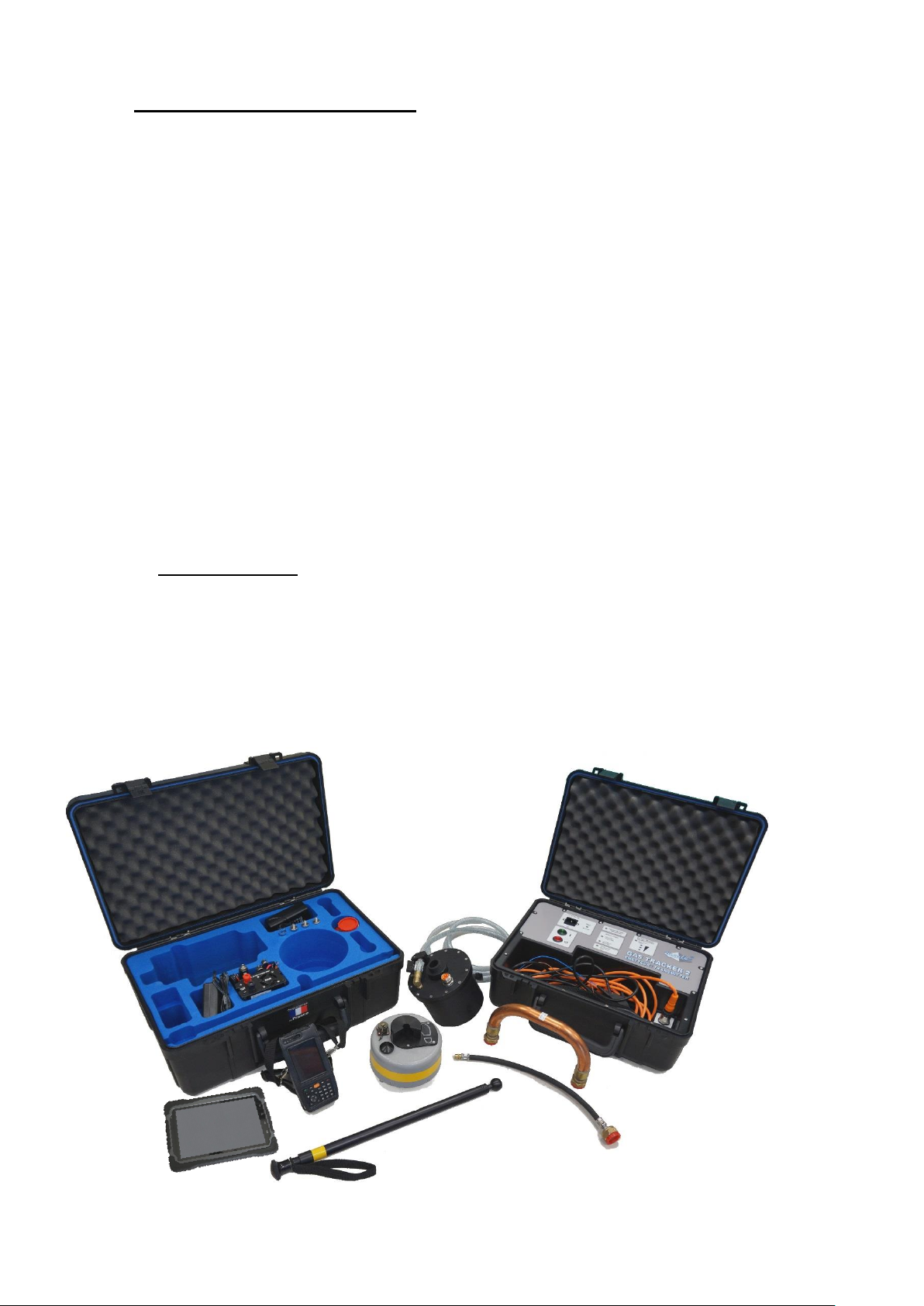
3.1. Gas Tracker set
GAS TRACKER 2 consists of :
A carrying case containing the transmitter, the injection box, and associated connectors,
A carrying case containing the PDA (or tablet) receiver, the acquisition ground sensor,
the charger, and connection accessories.

gu_gas_tracker2_v_2_15_en
7 / 35
3.1.1. Composition of the transmitter case
Carrying case with integrated transmitter.
Retaining strap
Connecting cable to transmitter (3m).
Flexible connection pipe (according to country option)
Purge tube
Supporting leg.
Cigarette lighter adapter
External power cable.
Safety Shunt
3.1.2. Composition of the receiver case
Carrying case
PDA receiver with carrying bag or tablet
PDA (or tablet) charger
Resonator tank
Sphero-conical fittings (optional)
U-shaped copper fitting (optional)
Acquisition ground sensor.
Telescopic rod
Set of long legs for the ground sensor
Charger for the ground sensor
Flexible connection for pressure tapping
User guide and plastic covered instruction sheet
gu_gas_tracker2_v_2_15_en
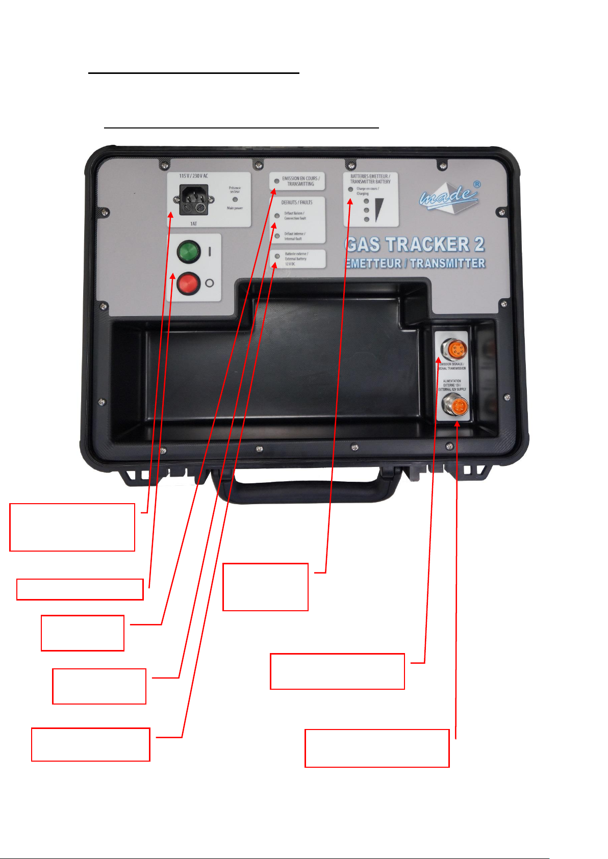
8 / 35
Transmitting
indicator
Default
indicator
External battery
power indicator
Battery
charge
indicator
Plug for connecting the
resonator tank
Mains power switch
Mains plug for
internal batteries
110-240V 50/60Hz
External 12V 3A power
supply plug
4. GAS TRACKER TRANSMITTER
The GAS TRACKER transmitter injects the acoustic signal into the gas network.
4.1. Description of the front panel of the transmitter
gu_gas_tracker2_v_2_15_en
9 / 35
4.2. Operation of the Gas Tracker transmitter
4.2.1. Power supply
The GAS TRACKER Transmitter can be operated on batteries or mains. The mains connection
recharges the internal batteries.
A plug for connecting to a vehicle battery (alligator clips) or a cigarette lighter socket is provided.
If this supply is used, the internal battery pack is deactivated.
Maximum consumption of the transmitter unit: 3A under 12V or 36W.
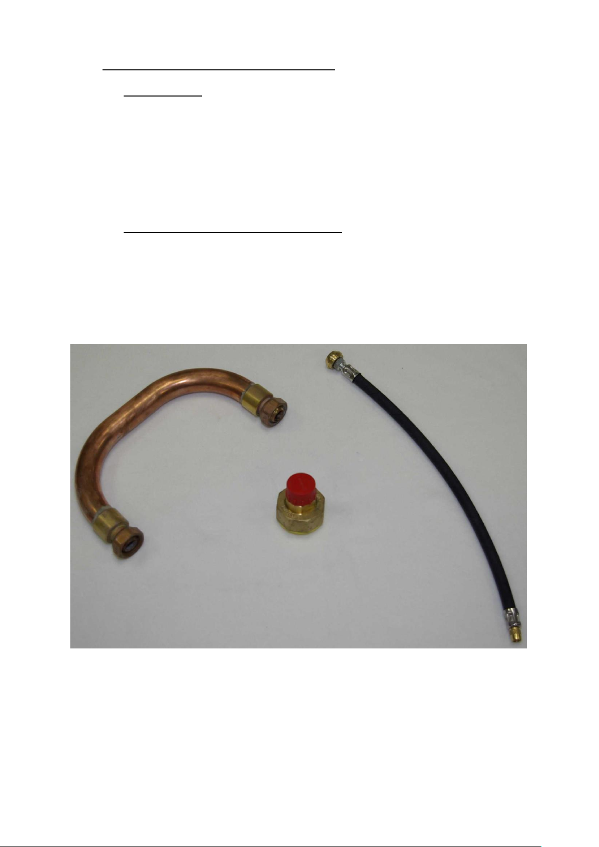
4.2.2. Connection to the transmitter network
A "U" connection Ø 20 makes it possible to connect directly to the customer shut-off
valve upstream of the meter or pressure regulator on 4-bar networks. Other adapters are
provided for different diameters.
A flexible connection for connection to the pressure connection (depending on country)
gu_gas_tracker2_v_2_15_en
10 / 35
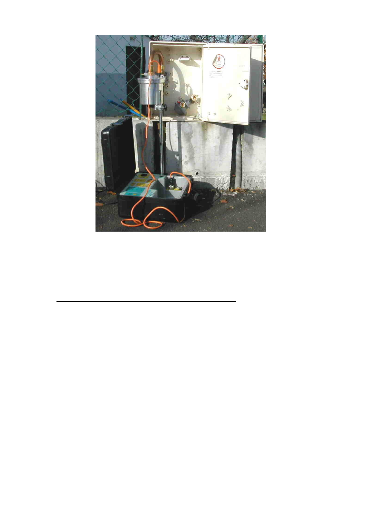
The resonator tank leans on the customer meter box. A supporting leg is integrated into the
handle of the tank. The leg is adjustable by a knob to accommodate the height of the box.
A retaining strap is provided for high installation.
4.2.3. Procedure for putting the transmitter into service :
In addition to the following instructions, please follow the procedures applicable at your local
gas network operator. transmitter allows the acoustic signal to be
1. Remove the meter
2. Connect the resonator tank to the inlet valve, the purge valve must be open. Use the supporting
leg and the copper fittings if required.
3. OPEN the GAS by SLOWLY OPENING the CUSTOMER TAP so as not to damage the inner
membrane.
4. Leave the drain valve open for 5 seconds and close.
5. Check the connection for leaks
6. Connect the power supply
7. Press the ON button (green)
The signal then propagates into the gas and vibrates the pipe.
Check the battery level, if it is orange or red then ,
o Use the external connection cord (connection to vehicle battery or cigarette lighter
adapter)

gu_gas_tracker2_v_2_15_en
11 / 35
o Connect to the mains using the cord provided to the transmitter (the transmitter
will be recharged during use).
4.2.4. Procedure for removing the transmitter :
1. Close the inlet valve
2. Switch off the transmitter and disconnect the electrical cable from the tank
3. Vent the tank by opening the drain valve for a few seconds (approx. 5 seconds) and then close it.
4. Replace the shunt connected to the gas tap and customer installation.
5. Remove the tank and take care not to damage the inlet valve
6. Reassemble the customer installation.
 Loading...