

Page 1
M
U
N
c
s
e
t
T
e
acurco™
ser Instru
itrogen D
tions
ioxide Det
ctor, Con
roller and
ransduc
r TX-6-ND
I
mportant:
Keep the
e User In
structions
1
for refere
nce
Page 2

TABLE OF CONTENTS
GENERAL SAFETY INFORMATION 3
Intended Use 3
List of Warnings and Cautions 3
USE INSTRUCTIONS AND LIMITATIONS 4
Use For 4
Do Not Use For 4
General Description 4
Features 4
Specifications 5
INSTALLATION AND OPERATING INSTRUCTIONS 5
Location 6
Installation 6
Garage diagram 6
4-20 mA Output diagram 6
Multiple Device diagram 7
Alarm Control Panel diagram 7
DVP-120 Control Panel diagram 8
Alternate Alarm Panel 8
Power Up 8
Operation 9
Default – Factory Settings 9
Display setting 10
Buzzer setting 10
Alarm Relay setting 10
Alarm Relay Configuration 10
Fan Relay setting 10
Fan Relay Delay setting 10
Fan Minimum Runtime setting 11
Fan Relay Latching setting 11
4-20mA Output setting 11
On Board Diagnostics 11
Sensor Poisons 12
MAINTENANCE 12
End-of-Warranty Signal 12
Sensor Replacement 12
Sensor Life Reset 13
Cleaning 13
Testing 13
Operation Test 13
Nitrogen Dioxide Test 15
Field Calibration Procedure 17
MACURCO GAS DETECTION PRODUCTS WARRANTY 18
2
Page 3

GENERAL SAFETY INFORMATION
Intended Use
The Macurco TX-6-ND is a low voltage, dual relay Toxic Gas (TX) detector, controller and transducer for
Nitrogen Dioxide (NO2). The TX-6-ND has selectable 4-20 mA output, buzzer and digital display options. It
is an electronic detection system used to measure the concentration of Nitrogen Dioxide and provide
feedback and automatic exhaust fan control to help reduce Nitrogen Dioxide concentrations in parking
garages, maintenance facilities or other commercial applications. The TX-6-ND is a low level meter capable
of detecting from 0-20ppm of Nitrogen Dioxide. The TX-6-ND is factory calibrated and 100% tested for
proper operation, but can also be calibrated in the field.
List of Warnings and Cautions within these User Instructions
! WARNING
Each person using this equipment must read and understand the information in these User Instructions
before use. Use of this equipment by untrained or unqualified persons, or use that is not in accordance
with these User Instructions, may adversely affect product performance and result in sickness or death.
Use only for monitoring the gas which the sensor and instrument are designed to monitor. Failure to do
so may result in exposures to gases not detectable and cause sickness or death. For proper use, see
supervisor or User Instructions, or call Technical Service at 1-877-367-7891.
This equipment may not function effectively below 0F or above 125F (-18C or above 52C). Using the
detector outside of this temperature range may adversely affect product performance and result in
sickness or death.
This detector helps monitor for the presence and concentration level of a certain specified airborne gas.
Misuse may produce an inaccurate reading, which means that higher levels of the gas being monitored
may be present and could result in overexposure and cause sickness or death. For proper use, see
supervisor or User Instructions, or call Technical Service at 1-877-367-7891.
High voltage relay terminals (120/240 VAC) are located within this detector, presenting a hazard to
service technicians. Only qualified technicians should open the detector case and service the internal
circuits. Ensure power is removed from the detector relays prior to servicing the unit. Failure to do so
may result in sickness or death.
Do not disassemble unit or attempt to repair or modify any component of this instrument. This instrument
contains no user serviceable parts, and substitution of components may impair product performance and
result in sickness or death.
Using a certified gas with a concentration other than the one listed for this detector when conducting a
calibration or calibration verification test (bump test) will produce inaccurate readings. This means that
higher levels of the gas being monitored may be present and could result in overexposure and cause
sickness or death. For proper use, see supervisor or User Instructions, or call Technical Service at 1877-367-7891
The following steps must be performed when conducting a calibration or calibration verification test
(bump test) to ensure proper performance of the monitor. Failure to do so may adversely affect product
performance and result in sickness or death.
When performing a calibration or calibration verification test (bump test) only use certified
calibration gas at the required concentration level. Do not calibrate with expired calibration gas.
If the instrument cannot be calibrated, do not use until the reason can be determined and
corrected.
Do not cover or obstruct display or visual alarm
Ensure sensor inlets are unobstructed and is free of debris
3
Page 4

USE INSTRUCTIONS AND LIMITATIONS
! WARNING
Each person using this equipment must read a nd understand the information in these U ser Instructions before use.
Use of this equipment by untrained or unqualified persons, or use that is not in accordance with these User
Instructions, may adversely affect product performance and result in sickness or death.
Use For
The TX-6-ND provides Nitrogen Dioxide detection and automatic exhaust fan control for parking garages,
loading docks, truck and bus depots, firehouses, ambulance bays, warehouses and maintenance facilities.
Nitrogen dioxide or NO2 is a toxic chemical of concern in diesel exhaust. The higher average temperature
of combustion of diesel engines generates more nitrogen oxides than gasoline engines. The TX-6-ND
meets the requirements of the Uniform Building Code for enclosed garages and meets OSHA standards for
Nitrogen Dioxide exposure. TX-6-ND can be used stand alone, with the Macurco DVP-120 Detection and
Ventilation Control Panel, other 12 VAC or 24 VDC fire/security panels or building automation systems.
! WARNING
Use only for monitoring the gas which the sensor and instrument are designed to monitor. Failure to do so may result
in exposures to gases not detectable and cause sickness or death. For proper use, se e supervisor or User
Instructions, or call Technical Service at 1-877-367-7891.
Do Not Use For
The TX-6-ND is not intended for use in hazardous locations or industrial applications such as refineries,
chemical plants, etc. Do not mount the TX-6-ND where the normal ambient temperature is below 0°F or
exceeds 125°F (below -18C or above 52C). The TX-6-ND mounts on a 4x4 electrical box supplied by the
contractor. Do not install the TX-6-ND inside another box unless it has good air flow through it.
! WARNING
This equipment may not function effectively below 0F or above 125F (-18C or above 52C). Using the detector
outside of this temperature range may adversely affect product performance and result in sickness or death.
General Description
The TX-6-ND is a low voltage, dual relay Nitrogen Dioxide (ND) detector and automatic ventilation
controller. The TX-6-ND uses a microcomputer controlled, electronic system to measure the concentration
of Nitrogen Dioxide, actuate relays and provide a 4-20mA output. The TX-6-ND has a field replaceable,
electrochemical sensor (expected life of 2+ years) and optional gas test and calibration kits. The TX-6-ND
is a low level meter capable of displaying from 0-20ppm of Nitrogen Dioxide.
Features
ETL Listed to UL 61010-1
Low level meter capable of displaying from 0-20 ppm Nitrogen Dioxide
The TX-6-ND meets Uniform Building Code for enclosed garages and OSHA standards for gas
exposure
Selectable fan and alarm relay activation
5 A SPDT fan relay controls starters of exhaust fans
0.5 A N.O. or N.C. alarm relay connects to warning devices or control panels
4-20 mA Current Loop
TX-6-ND mounts on a standard 4x4 electrical box and becomes cover for the box
Supervised system: any internal detector problem will cause the fan & alarm relay to activate
Calibration kit is available. One screw allows access for calibration or gas test
4
Page 5

Specifications
Power: 3 W (max) from 12 to 24 VAC or 12 to 32 VDC
Current @ 24 VDC: 75 mA in alarm (two relays), 50 mA (fan relay only) and 23 mA stand by
Shipping Weight: 1 pound (0.45 kg)
Size: 4 1/2 x 4 x 2 1/8 in. (11.4 X 10.2 X 5.4 cm)
Color: Dark gray
Connections: plugs/terminals
Mounting box: (not included) 4x4 electric
Fan relay: 5 A, 240 VAC, pilot duty, SPDT
Fan relay actuation: selectable at OFF, 0.2, 0.5, 0.7, 1.0, 1.2, 1.5, 1.7, 2.0, 2.2, 2.5 (default), 2.7,
3.0, 3.2, 3.5, 3.7, 4.0, 4.2, 4.5, 4.7, 5.0 ppm
Fan Delay Settings of 0, 1, 3 (default), 5 and 10 minutes
Fan Minimum Run Time settings are OFF (default), 3, 5, 10 or 15 minutes
Fan relay latching or not latching (default) selectable
Alarm relay: 0.5A 120 V, 60 VA
Alarm relay actuation: selectable N.O. (default) or N.C.
Alarm relay settings: OFF, 1, 2, 3, 4, 5 (default), 6, 7, 8, 9, 10, 11, 12, 13, 14, 15, 16, 17, 18, 19, 20
ppm
Current Loop: 4-20 mA for 0-20ppm NO2, selectable to off (default) or on
Buzzer: 85 dBA at 10cm settable to off (default) or on
Digital display: 3 digit LED selectable to off (default) or on.
Operating environ: 0°F to 125°F (-18C to 52C).10 to 90% RH
INSTALLATION AND OPERATING INSTRUCTIONS
The following instructions are intended to serve as a guideline for the use of the Macurco TX-6-ND Nitrogen
Dioxide Detector. It is not to be considered all-inclusive, nor is it intended to replace the policy and
procedures for each facility. If you have any doubts about the applicability of the equipment to your
situation, consult an industrial hygienist or call Technical Service at 1-877-367-7891.
! WARNING
This detector helps monitor for the presence an d concentrati on level of a certain spe cified airborne gas. Misuse may
produce an inaccurate reading, which m eans that h igher le vels of the gas being monit ored may be present and coul d
result in overexposure and cause sickness or death. For pr oper use, see supervisor or User Instructions, or call
Technical Service at 1-877-367-7891.
Location
A TX-6-ND is normally mounted at breathing level, about 5 feet (1.5 meters) above the floor on a wall or
column in a central area where air movement is generally good. The unit, on average, can cover about
5,000 sq. ft. (465 sq. meters). The coverage depends on air movement within the room or facility. Extra
detectors may be needed near any areas where people work or where the air is stagnant. Do NOT mount
the TX-6-ND where the normal ambient temperature is below below 0°F or exceeds 125°F (below -18C or
above 52C).
! WARNING
High voltage relay terminals (120/240 VAC) are located within this detector, presenting a hazard to service
technicians. Only qualified technicians should open the detector case and service the internal circuits. Ensure power
is removed from the detector relays prior to servicing th e unit. Failure to do so may result in sickness or death.
5
Page 6
Installation
1. The TX-6-ND mounts on a 4” square (or 4x4) electrical box supplied by the contractor. Do not mount
the TX-6-ND inside another box, unless it has good air flow through it.
2. Connect the TX-6-ND to Class 2 power supply only. It is suggested to use a separate transformer for
powering the unit or units because of possible interference’s from other devices on the same power
supply.
3. Connect the TX-6-ND to the control cables with terminal plugs. When making connections, make sure
the power is off.
4. There are two terminals for Power: 12 to 24 VAC or 12 to 32 VDC, with no polarity preference.
5. There are two terminals for the dry alarm relay contacts, again with no polarity preference. The alarm
relay can switch up to 0.5 A 120 V, or 60 VA. The alarm relay is activated if gas reaches or exceeds the
alarm settings. See OPERATION section of these User Instructions for details on relay settings.
6. The alarm relay can be configured to normally open (default) (N.O.) or normally closed (N.C.) and will
activate if the gas concentration exceeds alarm set point. It will deactivate once the gas concentration
drops below the alarm set point. Note that the “disable” setting will cause the alarm relay not to engage
at all.
7. The dry contact, SPDT fan relay has three terminals. The common (COM.), normally open (N.O.) and
the normally closed (N.C.) contact. The fan relay can switch up to 5.0 A up to 240 VAC. See
OPERATION section of these User Instructions for details on relay settings.
8. The Fan Relay can be configured for latching or non-latching (default) when activated (when the gas
concentration exceeds fan relay set point).
9. The Fan Relay will engage if the fan setting Nitrogen Dioxide concentration is exceeded for longer than
the Fan Relay Delay time. Unless it is configured for latching, the fan relay will disengage once both of
these conditions have been met:
Nitrogen Dioxide concentration has dropped below fan setting
Fan Relay Run time has been exceeded
Note that the “disable” fan setting will cause the fan relay to not engage. The fan relay will engage in
trouble fault condition and will disengage once trouble fault condition is cleared.
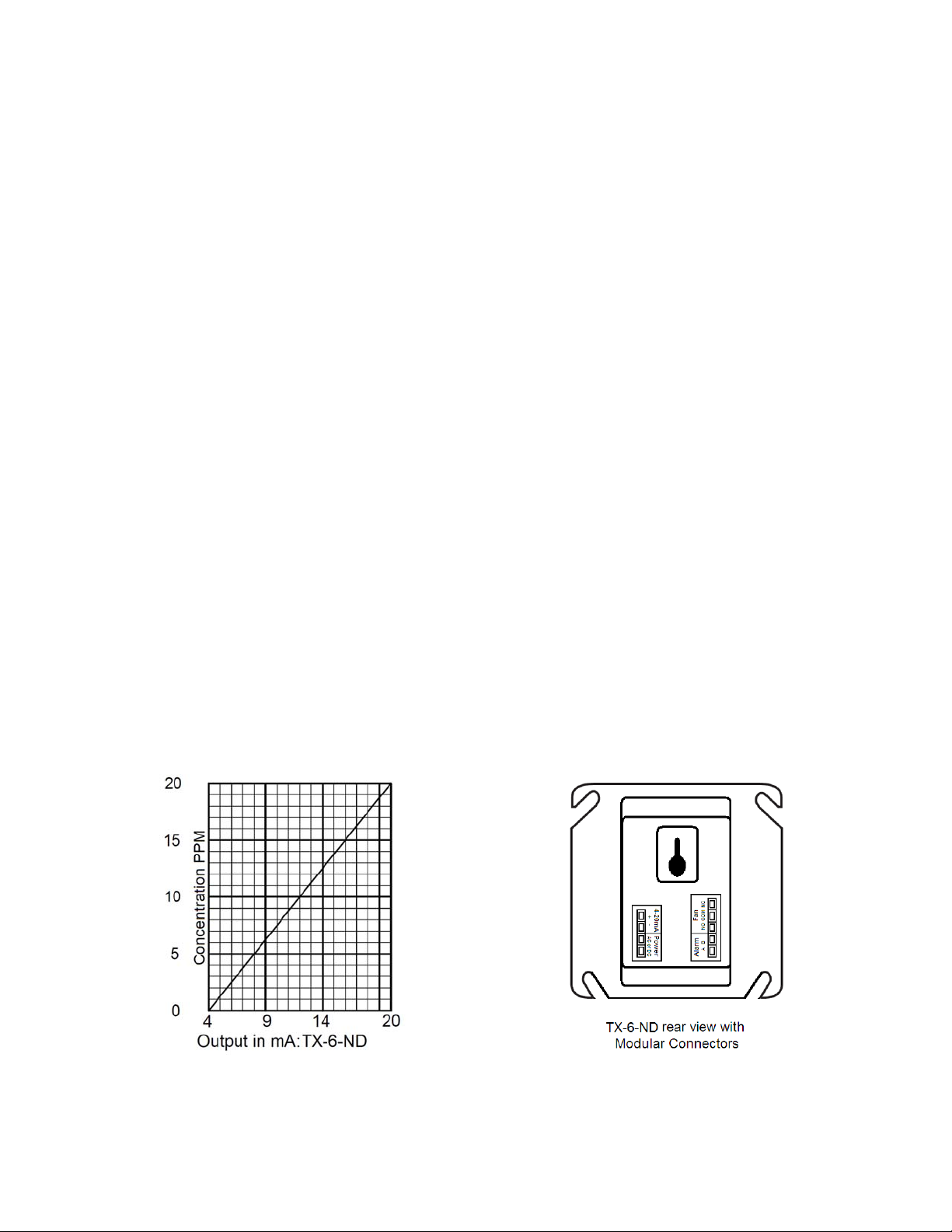
10. The Current Loop is 4 mA in clean air and 20 mA for 20 ppm Nitrogen Dioxide
6
Page 7

7
Page 8

p
-
h
p
u
r
r
y
w
r
c
e
n
b
E
l
p
f
g
n
e
w
r
w
D
c
n
e
g
w
e
n
Power U
The TX-6
execute t
cycle the
normal o
Test” (PU
the 1 min
ND steps th
e test cycle
unit will displ
eration. The
t) option is O
te cycle, the
ough an inte
any time po
the Firm
a
Fan and Ala
FF. The indi
unit will take
nal self-test
wer is dropp
are Version
m relay will
ator light (L
its first samp
cycle for the
d and reap
umber, then
e activated
D) will flash
e of the air a
8
first 1 minut
lied (i.e. po
count down
or the powe
reen during
d the indicat
that it is po
er failure).
from 60 to 0
-up cycle unl
the self-test
or light will tu
ered. The u
uring the s
and finally
ess the “Po
cle. At the
rn solid gree
it will
lf-test
o into
er Up
nd of
.
Page 9

Operation
1. With the display function turned “On”, the TX-6-ND will show the current concentration of NO2 ppm or
“0.0” (zero) in clean air. When the NO2 concentration reaches the Fan Relay setting (1.0ppm, for
example) the display will flash back and forth between “FAn” and “1.0”. With the display function turned
”Off”, the display does not show the gas concentration, but will show “FAn” as long as the fan relay is
activated.
2. With the display function turned “On” and the NO2 concentration reaching the Alarm Relay setting,
(5.0ppm, for example) the display will flash back and forth between “ALr” and “5.0”. The buzzer will
sound indicating “Alarm” if the buzzer is turned “On”. With the display function turned off the display
does not show the NO2 concentration, but will show “ALr” when the Alarm relay is activated.
3. With the 4-20 mA function turned “On” and the NO2 concentration climbing the 4-20 mA signal will
ramp up corresponding to the concentration (0-20 ppm).
Default Configuration – Factory Settings
The default Power Up Test setting is On
The default Display setting is Off
The default Buzzer setting is Off
The default Alarm Relay Setting is activation at 5.0 ppm
The default Alarm Relay Configuration is Normally Open
The default Fan Relay Setting is activation at 2.5 ppm
The default Fan Relay Delay setting is 3 minutes
The default Fan Relay Runtime setting is OFF
The default Fan Relay Latching condition is OFF
The default 4-20mA Output setting is OFF
To change settings, remove the Philips screw on the front of the TX-6-ND. Pull off the front cover of the
unit.
Selecting Default Configuration – “dEF”
To select the Default Configuration, in normal mode, push the Next button to get to “Con” or the
Configuration menu. Then push the Enter button to enter the Con menu. The first selection is the “dEF” or
Default setting. Push Enter. If it is already in Default configuration, there will be no action. If it is not already
in Default configuration, “nO” will be displayed. Push Next to change it to “YES” (flashing) then push Enter
to confirm the change (solid) and push Enter again to return to “dEF” in the con menu. Push Next until
“End” is displayed then push Enter to get back to normal operation.
9
Page 10

Selecting Power Up Test Option – “PUt”
To select the Power Up Test Configuration, in normal mode, push the Next button to get to “Con” or the
Configuration menu. Then push the Enter button to enter the Con men u. Then push the Next button to get to the
second selection “PUt” or Power Up Test setting. Push Enter. If the test is “On” push Next to turn it “OFF”
(flashing) then push Enter to confirm t he change (solid) and push Enter ag ain to return to “PUt” in t he Con menu.
Push Next until “End” is displaye d then push Enter to get back to normal operation.
Selecting Display Option – “dSP”
To select the Display Configuration, in normal mode, p ush the Next button to get to “Con ” or the Conf igur ation men u.
Then push the Enter button to enter the Con menu. Then push the Next button to get to the third selection “dSP” or
Display setting. Push Enter. If the display is “On” push Next to turn it “OFF” (flashing) then push Enter to confirm the
change (solid) and push Enter again to return to “dS P” in the Con menu. Push Next until “End” is displayed then
push Enter to get back to normal operation.
Selecting Buzzer Option – “bUZ”
To select the Buzzer Configuration, i n normal mo de, push t he Next button to get to “Con” or th e Config uration me nu.
Then push the Enter button to enter the Con menu. The forth selection is the “bUZ” or Buzzer setting. Push Next
three times to get to “bUZ” then Enter. If the display is “On” push Next to turn it “OFF” (flashing) t hen push Enter to
confirm the change (solid) and push Enter again to return to “bUZ” in the Con menu. Push Next until “End” is
displayed then push Enter to get back to normal operation.
Selecting Alarm Relay Setting – “ArS”
To select the Alarm Relay Setting, in normal mode, push the Next button to get to “Con” or the Configuration me nu.
Then push the Enter button to enter the Con menu. The fifth selection is the “ArS” or Alarm Relay Setting. Push
Next four times to get to “ArS” then Enter. If the display is “OFF” (disabled) push Next to change it to 1, 2, 3, 4, 5, 6,
7, 8, 9, 10, 11, 12, 13, 14, 15, 16, 17, 18, 19 or 2 0ppm (flashing) then push Enter to confirm the change (solid) and
push Enter again to return to “ArS” in the Con menu. Push Next until “End” is displ ayed then push Enter t o get bac k
to normal operation.
Selecting Alarm Relay Configuration – “Arc”
To select the Alarm Relay Configuration, in normal m ode, pus h t he Next button to get to “Con” or the C onfi gurati o n
menu. Then push the Enter button to enter the Con menu. The sixth selection is the “Arc” or Alarm Relay
Configuration. Push Next five times to get to “Arc” then Enter. If the relay is “nO” (normally open) push Next to turn it
to “nC” (flashing) then push Enter to confirm the chang e (solid) and push Enter again to return to “Arc” in the Con
menu. Push Next until “End” is displayed then push Enter to get back to normal operation.
Selecting Fan Relay Settings – “FrS”
To select the Fan Relay setting, in normal mode, push the Next button to get to “C on” or the Configuration menu.
Then push the Enter button to enter the Con menu. The seventh selection is the “FrS” or Fan Relay setting. Push
Next six times to get to “FrS” then Enter. If the fan relay is “OFF” (disabled) push Next to change it to 0.2, 0.5, 0.7,
1.0, 1.2, 1.5, 1.7, 2.0, 2.2, 2.5, 2.7, 3.0, 3.2, 3.5, 3.7, 4.0, 4.2 , 4.5, 4. 7, 5.0 p pm (flashi ng) the n push Enter to c onfirm
the change (solid) and push Enter again to retur n to “run” in the Con menu. Push Next until “End” is displayed t hen
push Enter to get back to normal operation.
Selecting Fan Relay Delay – “FrD”
To select the Fan Relay Delay setting, in normal mode, push the Next button to get to “Con” or the Configur ation
menu. Then push the Enter button to enter the Con menu. The eighth selection is the “FrD” or Fan Relay Delay.
Push Next seven times t o get to “FrD” then Enter. If the delay is “OFF” (dis abled) push Next to change it to 1, 3, 5,
or 10 minutes (flashing) then push Enter
Con menu. Push Next until “End” is displayed then p ush Enter to get back to normal operation.
to confirm the change (solid) a nd push Enter again to return to “FrD” in the
10
Page 11

Selecting Fan Relay Run Time – “Frr”
To select the Fan Minimum Runtime setting, in normal mode, push the Next button to get to “Con” or the
Configuration menu. Then push the Enter button to enter the Con menu. The ninth selection is the “Frr” or
Fan Minimum Run Time. Push Next eight times to get to “Frr” then Enter. If the runtime is “OFF” (disabled)
push Next to change it to 3, 5, 10 or 15 minutes (flashing) then push Enter to confirm the change (solid)
and push Enter again to return to “run” in the Con menu. Push Next until “End” is displayed then push
Enter to get back to normal operation.
Selecting Fan Relay Latching Option – “FrL”
To select the Fan Relay Latching Option, in normal mode, push the Next button to get to “Con” or the
Configuration menu. Then push the Enter button to enter the Con menu. The tenth selection is the “FrL”
or Fan Relay Latching Option. Push Next nine times to get to “FrL” then Enter. If latching is “OFF” push
Next to turn it to “ON” (flashing) then push Enter to confirm the change (solid) and push Enter again to
return to “FrL” in the Con menu. Push Next until “End” is displayed then push Enter to get back to normal
operation.
Selecting 4-20mA Output Option – “420”
To select the 4-20mA Output Option, in normal mode, push the Next button to get to “Con” or the
Configuration menu. Then push the Enter button to enter the Con menu. The eleventh selection is the
“420” or 4-20mA Output Option. Push Next ten times to get to “420” then Enter. If the 4-20mA is “On” push
Next to turn it to “OFF” (flashing) then push Enter to confirm the change (solid) and push Enter again to
return to “420” in the Con menu. Push Next until “End” is displayed then push Enter to get back to normal
operation.
Onboard Diagnostics
The TX-6-ND monitors all critical functions of the unit through software diagnostics that continuously test
and verify unit operations. If a problem is found, the unit will switch to a fail-safe/error mode or trouble
condition. In this error mode, the Fan and Alarm relays will be activated, the 4-20 mA current loop will go to
24 mA, the unit will display the error code and the buzzer will chirp intermittently. This is a safety
precaution. To clear this mode, simply turn off power to the unit for a few seconds, or push the TEST switch
(inside the unit). This will cause the unit to restart the 1 minute self-test cycle.
The 4-20 mA signal can be used for troubleshooting:
0 mA is most likely a connection problem
4-20 mA is normal gas reading range (0-20 ppm)
24 mA indicates a Trouble condition
Error Codes
t01 Sensor is missing
t02 Temperature compensation failed
t04 Bad EEPROM checksum
t08 Sensor is shorted
t10 Bad EEPROM
t20 Bad factory calibration
t40 Factory calibration was not done
t80 SDADC reading failed
t100 Under range sensor
t200 Sensor warranty expired
11
Page 12

NOTE: For trouble codes over 080 the display will alternate between t_1 and t00 for t100 and between t_2
and t00 for t200.
If the error mode repeats frequently, check for continuous power and proper voltage. If power is not the
problem and a unit has repeating error conditions, it may need to be returned to Macurco for service,
per these User Instructions.
If the error mode indicates “Sensor warranty expired” see the Sensor Replacement section of these
User Instructions.
Sensor Poisons
The gas sensor in the detector is designed with extreme sensitivity to the environment. As a result, the
sensing function may be deteriorated if it is exposed to a direct spray from aerosols such as paints, silicone
vapors, etc., or to a high density of corrosive gases (such as hydrogen sulfide, sulfur dioxide) for an
extended period of time.
MAINTENANCE
The TX-6-ND requires periodic maintenance. The unit uses an electrochemical sensor with a 2-3 year life
expectancy that can be tested, calibrated and replaced in the field. The TX-6-ND replacement sensor is
available through your local representative or from Macurco. All other maintenance and repair of products
manufactured by Macurco are to be performed at the appropriate Macurco manufacturing facility. Macurco
does not sanction any third-party repair facilities.
End-of-Warranty Signal
Two years after the TX-6-ND is installed the sensor end-of-warranty signal will be activated indicating that
the TX-6-ND sensor has reached the end of its warranty period. The end-of-warranty signal will cause an
error code t200 “Sensor warranty expired”. See Error Codes section. In addition to the end-of-warranty
signal the sensor itself has a tamper proof warranty expiration sticker dated 2 years from the unit
manufacture date. See the Macurco Fixed Gas Detection Products Limited Warranty section.
The end-of-warranty signal can be silenced for 48 hours by pressing the "ENTER/TEST" button or by
temporarily dropping power to the unit. The end-of-warranty signal provides the user an opportunity to test
and/or calibrate the sensor assuring that it is still performing within acceptable parameters though the
sensor is nearing the end of its 2-3 year expected life. The silence function will continue to be available for
29 days after the TX-6-ND initiates the initial end-of-warranty signal. After this 29 day period the TX-6-ND
can no longer be silenced and the sensor must be replaced or the sensor life reset.
Sensor Replacement
1. Remove power to the unit
2. Remove the Philips screw on the front of the TX-6-ND. Pull the front cover of the unit off.
3. Remove the sensor by pulling it gently from the three pronged sock et.
4. Remove the Shorting Spring from the new sensor and insert the new sensor into the socket.
5. Power up the unit. The TX-6-ND steps through an int ernal self-test cycle for the first 1 minute that it is
powered. During the self-test cycle the unit will display the Firmware Version number, then count down
from 60 to 0 and finally go into normal operation. The indicator light (LED) will flash green during the selftest cycle. At the end of the 1 minute cycle, the unit will take its first sample of the air and the indicator
light will turn solid green.
6. Let the new s ensor stabilize for at least 5 minutes then refer to the FIELD CALI BRATION PROCEDURE
section to zero and calibrate the unit.
7. After the successful calibration is complete, reset the sensor life.
12
Page 13

Sensor Life Reset
1. Remove the Philips screw on the front of the TX-6-ND. Pull the front cover of the unit off.
2. To reset the sensor life (rSt), from normal or warm-up mode, press the Next button four times to get to
SEn or Sensor Mode.
3. Then press the Enter button to get to “rSt” - Reset Sensor Mode.
4. Press the Enter button again to see the sensor reset status. If the sensor life has already been reset,
done “don” will be displayed. If it has not already been reset, “no” will be displayed. Push Next to change
it to “YES” (flashing) then push Enter to confirm the change (solid) and push Enter again to return to
“rSt” in the SEn menu. Push Next until “End” is displayed then push Enter to get back to normal
operation.
NOTE: If the sensor is reset and not replaced it is necessary to test and/or calibrate the sensor to assure
that it is still performing within acceptable specifications though the sensor is nearing the end of its 2-3 year
expected life. There will be no other indication of sensor performance.
! WARNING
Do not disassemble unit or attempt to repair or modify any component of this instrument. This instrument
contains no user serviceable parts, and substitution of components may impair intrinsic safety, which may
adversely affect product performance and result in sickness or death.
CAUTION
Avoid the use of harsh cleaning materials, abrasives and other organic solvents. Such materials may
permanently scratch the surfaces and damage the display window, labels, sensor or instrument housing.
Cleaning
Cleaning of the external surfaces is best carried out using a damp cloth with a mild detergent or soap. Use
a vacuum cleaner with soft brush to remove dust or contamination under the cover. Do not blow out the
sensor with compressed air.
TESTING
! WARNING
Using a certified gas with a concentration other than the one listed for this detector when conducting a
calibration or calibration verification test (bump test) will produce inaccurate readings. This means that
higher levels of the gas being monitored may be present and could result in overexposure and cause
sickness or death. For proper use, see supervisor or User Instructions, or call Technical Service at 1-877367-7891
General
All TX-6-ND units are factory calibrated and 100% tested for proper operation. The unit also performs a
regular automatic self-test during normal operation. If the unit detects an improper voltage or inoperable
component, it will default into Error mode. In this error mode, the Fan and Alarm relays will be activated, the
4-20 mA output will go to 24 mA, the unit will display the error code and the buzzer will chirp intermittently.
Operation Test
Normally this will be the only test required for the TX-6-ND and is the recommended way to test the unit or
units after installation. Check that the green TX-6-ND operating LED light is illuminated continuously. If not,
do not proceed with the tests. If the unit is in error mode contact your local representative or Macurco
technical service representative for information on resolving the problem.
13
Page 14

1. Remove the single screw in the middle of the front cover of the TX-6-ND.
2. Remove the front cover.
3. Locate the switch labeled ENTER/TEST on the left side of the printed circuit board.
4. Observe the LED light on the front of the TX-6-ND.
5. If the light is solid green proceed to step 7.
6. If the light is off or flashing Green, refer to the General section above.
7. Push the Test switch once.
8. The TX-6-ND will step through a cycle test:
a) The display progresses through the brt (buzzer test), Art (alarm relay test), Frt (fan relay test)
then 42t (4-20 mA output test).
b) During the first 3 seconds of the test cycle, the Buzzer will sound
c) During the next 5 seconds of the test cycle, the Alarm relay will be closed, so any devices
connected to that relay will be tested.
d) The Fan relay will be activated for the next 1 minute of the test, so if the fan circuits are wired
in the normal manner, the fan should run.
e) The 4-20mA output will then ramp up from 4 to 20 mA over the next 130 seconds of the test,
so if the circuit is wired in the normal manner, the control panel or building automation system
should respond.
f) At the end of the test cycle, the light will turn green and be on steady (Normal Operation), the
Fan & Alarm relay will be in standby mode and the 4-20 mA output will return to 4 mA (in clean
air).
11. When testing is completed reassemble the unit or units.
Manual Operation Test
This option gives the user the opportunity to manually initiate an individual test for each relay, the analog
output and the sensor response to gas. From normal operation mode press the Next button 2 times to get
to the Test Mode (tSt). Press the Enter button once to get into the Test Menu. Press the Next button to
scroll through the five test options and press Enter to initiate the selected test. Note that if the relay or 4–20
mA output has been disabled, the test selection will not be displayed in the test menu.
brt – Buzzer Test, 3 seconds
Art - Alarm Relay Test, 10 seconds
Frt - Fan Relay Test, 60 seconds
42t - 420 loop test, 25 seconds
gtS - Gas Test, 3 minutes (no output to the panel during the gas test)
The display will flash during the test, or in the case of the gas test, the gas level will alternate with gtS.
Once the test is complete, the display will return to steady display. To exit the test menu, press the Next
button until “End” is displayed, then press Enter to return to normal mode.
14
Page 15

Nitrogen Dioxide Gas Test
! WARNING
The following steps must be performed when conducting a calibration or calibration verification test (bump
test) to ensure proper performance of the monitor. Failure to do so may adversely affect product
performance and result in sickness or death.
When performing a calibration or calibration verification test (bump test) only use certified
calibration gas at the required concentration level. Do not calibrate with expired calibration gas.
If the instrument cannot be calibrated, do not use until the reason can be determined and
corrected.
Do not cover or obstruct display or visual alarm cover.
Ensure sensor inlets are unobstructed and is free of debris
General
The TX-6-ND can be bump-tested or calibrated with the ND-FCK with Nitrogen Dioxide gas, regulator and
test hood, available through your local representative or from Macurco.
Contents of the FCK
ND-FCK: (1) Gas Cylinder, 5 ppm Nitrogen Dioxide gas in air
Gas regulator with about two feet of plastic tubing
Gas test hood
FCK Information
Several detectors can be calibrated with one FCK. The only limitation is the amount of gas in the cylinder
and the flow of the regulator. The 34 liter cylinder for example with a 0.2LPM regulator has approximately
170 minutes of continuous calibration run time. Replacement cylinders are available. The gas cylinder
should be replaced when the pressure gauge on the regulator shows 25-psi or less.
Note: For optimum test results it is suggested that the unit be in clean air (green light on) and be in a low
ambient air flow
Gas Testing
Testing the Fan Relay –
1. Remove the Philips screw on the front of the TX-6-ND. Remove the front cover.
2. Open the FCK. Connect the 5 ppm gas cylinder to the regulator.
3. Check the pressure gauge on the regulator. If you have 25-psi or less you will need to replace the gas
canister.
4. Assemble regulator, hose and test hood and place the Test Hood over the gas sensor.
Note: The time to activate the Fan relay depends on the delay setting.
15
Page 16

5. Turn on the regulator to start the gas flow and wait with the gas applied continuously.
6. With the display function turned “On”, the TX-6-ND will show the current concentration of gas or “0.0”
(zero) in clean air. When the gas concentration reaches the Fan Relay setting (1.0 ppm, for example)
the display will flash back and forth between “FAn” and “1”. With the display function turned ”Off”, the
display does not show the gas concentration, but will show “FAn” as long as the fan relay is activated.
Note: If the Fan relay does not close within 2 minutes, there are four possibilities:
a. Gas cylinder is empty, check the pressure gauge. Replace the gas cylinder if 25psi or less.
b. Unit needs to be re-calibrated (go through recalibration and re-test).
c. Detector is in need of servicing (return unit to factory for servicing).
d. Detector has fan relay set to disable (OFF). Set fan relay to 3 ppm and repeat the test.
e. Detector has fan relay delay set to 3 minutes. Set fan relay to 0 minutes and repeat the test.
f. Remove the gas from the sensor. Proceed to Test the Alarm relay or replace the top cover.
Fan relay test is complete.
Testing the Alarm Relay
Note: The gas concentration to activate the Alarm relay depends on the setting.
1. Connect the 5 ppm cylinder of Nitrogen Dioxide to the regulator.
2. Check the pressure gauge. If there is 25psi or less the cylinder should be replaced.
3. Place the test hood over the gas sensor. Turn on the regulator to start the gas flow.
4. The Fan relay should activate according to the settings.
5. With the display function turned “On” and the gas concentration reaching the Alarm Relay setting, (5.0
ppm, for example) the display will flash back and forth between “ALr” and “5.0”. The buzzer will sound
indicating “Alarm” if the buzzer is turned “On”. With the display function turned off the display does not
show the gas concentration, but will show “ALr” when the Alarm relay is activated.
Note: If the Alarm relay fails to operate within 2 minutes, there are four possibilities:
a. Gas cylinder is empty, check the pressure gauge. Replace the gas cylinder if 25-psi or less.
b. Unit needs to be re-calibrated (go through recalibration and re-test).
c. Detector is in need of servicing (return unit to factory for servicing).
d. Detector has Alarm relay set to disable (OFF). Set Alarm relay to 5 ppm and repeat the test.
6. Remove the gas from the sensor after Test. Proceed to Test the 4-20mA output or replace the top
cover. Alarm relay test is complete.
Testing the 4-20mA current loop
1. Connect the 5 ppm cylinder of Nitrogen Dioxide to the regulator.
2. Check the pressure gauge. If there is 25-psi or less the cylinder should be replaced.
3. Place the test hood from the regulator over the gas sensor. Turn on the regulator to start the gas flow.
4. The Fan relay should activate according to the settings.
5. The Alarm relay should activate according to the settings.
6. The 4-20 mA output should ramp up from 4mA in clean air to 8 mA at 5 ppm. See 4-20 mA diagram on
page 6.
Note: If the 4-20mA output does not ramp up within 2 minutes, there are four possibilities:
a. Gas cylinder is empty, check the pressure gauge. Replace the gas cylinder if 25-psi or less.
b. Unit needs to be re-calibrated (go through recalibration and re-test).
c. Detector is in need of servicing (return unit to factory for servicing).
d. Detector has 4-20 mA option set to “OFF”. Set 4-20mA option to “On” and repeat the test.
16
Page 17

7. Remove the gas from the sensor. Re-assemble the TX-6-ND (make sure the LED is aligned with the
front case hole). 4-20 current loop test is complete.
FIELD CALIBRATION PROCEDURE
Note: For optimum calibration results the unit should be in clean air and be in a low ambient air flow.
Zero the Sensor
1. Ensure that the ambient air has less than 0.1 ppm NO2 before proceeding with Zeroing the sensor.
Remove the Philips screw on the front of the TX-6-ND. Pull the front cover of the unit off.
2. To select Calibration Zero Mode (000), from normal mode, press the Next button three times to get to
CAL or Calibration Mode.
3. Then press the Enter button to get to “000” - Calibration Zero Mode.
4. Press the Enter button and the display will read 0.0 alternating with 000 (blinking) indicating zero
calibration in progress (max 165 sec).
5. If the process is successful, the display will read 0.0 alternating with PAS (blinking) Zero Calibration
complete.
6. If the process was not successful the display will read __1 alternating with FAL (Fail) (blinking) Zero
Failed. If this occurs, repeat steps 2 through 4. If the sensor fails to zero twice contact Technical
Assistance: 1-877-367-7891.
7. To return to Normal Mode press Enter and then press Next until “End” is displayed. Press Enter to
return to Normal Mode.
Calibration
1. Remove the Philips screw on the front of the TX-6-ND. Pull the front cover of the unit off.
2. Assemble the 5 ppm gas cylinder and regulator together.
3. Check the pressure gauge on the regulator. If you have 25-psi or less you will need to replace the gas
canister.
4. Place the test Hood from the regulator over the gas sensor.
5. Push Next 3 times to get to the CAL menu then push Enter. Press Next once to get to Span mode then
press Enter, the display will flash back and forth between GAS and 5.0.
6. Start applying 5.0 ppm gas to the gas sensor by turning on the valve on the regulator.
Note: The sensor will look for the gas for 45 seconds. If no gas is applied or detected in that time, the
display will return to CAL.
7. When the sensor detects the gas, the display will flash back and forth between the gas concentration
and SPn, then the calibration will progress and the display will show the gas level for a maximum of
165 seconds.
8. When the calibration is successful, the display will flash back and forth between the gas concentration
and PAS, then the display will show the calibration gas level and the calibration is done.
9. If the calibration fails, the display will flash back and forth between the gas concentration and FAL (fail).
If this occurs, check the pressure gauge on the regulator. If the pressure is less than 25 psi the flow of
gas may not be adequate to properly calibrate the unit. If there is proper pressure in the cylinder repeat
steps 4 through 6. If the unit fails to calibrate twice contact Technical Assistance: 1-877-367-7891
10. Once the calibration has passed, remove gas and disassemble the cylinder and regulator.
11. Re-assemble the TX-6-ND (make sure the LED is aligned with the front case hole). Calibration is
complete
12. See Calibration Flowchart on the inside of the housing.
17
Page 18

MACUR
C
w
t
a
n
s
n
v
N
A
a
e
n
u
o
o
-
2
A
s
d
h
n
u
a
,
n
1
s
i
O
s
r
n
w
e
a
(2)
F
s
g
b
d
T
n
u
a
p
T
P
o
s
t
W
m
s
w
w
t
o
e
c
o
m
o
n
o
u
y
d
X
m
d
E
t
s
p
t
P
E
o
n
t
d
Macurco
period of
is maint
compone
the unit i
have bee
The abo
WARRA
PERIO
incidental
of or rel
replacem
repayme
Manufact
Round R
Email: inf
Phone: 1
Rev 9.19
© Aerionics
Macurco is a
O FIXED G
arrants the
wo (2) years
ined and u
t becomes
returned in
altered or
e warranty i
TIES OF ME
D OF TWO
or conseque
ted to the
nt or repair
t of the price
red by Aerio
ck, Texas
aerionicsi
877-367-789
.2012
012. All rights re
trademark of Aer
S DETECTI
TX-6-ND ga
from date of
ed in acco
efective duri
accordance
ad repair att
s in lieu of
RCHANTABI
YEARS
tial damage
se of said
s set forth a
or repair an
ics, Inc.
c.com
erved.
onics, Inc.
N PRODUC
detector wil
manufacture
dance with
the warra
ith the instr
mpted, or th
ll other ex
LITY AND FI
ROM THE
for breach
as detector.
ove. Buyer’
replacemen
S LIMITED
be free fro
indicated on
Macurco in
ty period, it
ctions belo
t have been
ress warran
NESS FOR
URCHASE
f this or any
Manufactur
sole and ex
of non-conf
ARRANTY
defective
the inside c
tructions an
ill be replac
. This warra
subjected to
ies, obligati
PARTICULA
DATE. Mac
ther warrant
r or its age
lusive reme
rming goods
aterials and
ver of the T
d/or recom
ed or repaire
nty does not
abuse, acci
ns or liabiliti
R PURPOS
rco shall no
, express or
nt’s liability
ies are retur
or parts.
workmanshi
-6-ND), prov
endations. I
d free of cha
apply to uni
ental or othe
es. THE IM
ARE LIMIT
be liable f
implied, arisi
hall be limi
n of the goo
for a
ided it
f any
rge, if
s that
rwise.
LIED
D TO
r any
out
ed to
s and
18
 Loading...