

Page 1

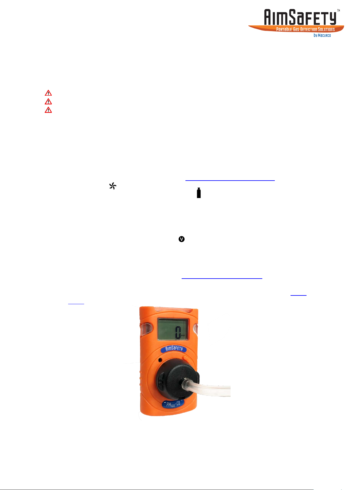
AimSafety PM
Personal Single Gas Monitor
User’s Manual
100
P/N 34-2900-0206-2 Rev. A
July 2018
Page 2

PM
Page 2
User’s Manual
100
Table of Contents
1. General Information ............................................................................................... 4
2. Specifications .......................................................................................................... 5
3. Product Overview ................................................................................................... 6
4. Activation................................................................................................................ 7
5. User Interface ......................................................................................................... 8
6. Bump Test ............................................................................................................. 14
7. Calibration ............................................................................................................ 16
8. Event Log .............................................................................................................. 19
9. Maintenance and Cleaning ................................................................................... 20
10. Disposal ................................................................................................................ 21
11. Certificates ............................................................................................................ 21
12. Limited Warranty .................................................................................................. 22
13. Contact Information ............................................................................................. 22
Page 3
PM
Page 3
User’s Manual
100
WARNING
Any unauthorized attempt to repair or modify the product, or any other cause of
damage beyond the range of the intended use, including damage by fire, lightning,
or other hazard, voids liability of the manufacturer.
Activate this product only if sensor, visual, detection, and audible cover are clear from
contaminants such as dirt and debris that could block the area where gas is to be
detected.
Do not clean and rub the LCD screen of the products with a dry cloth or hands in
hazardous environment to prevent static electricity.
Perform cleaning and maintenance of the products in fresh air that is free of
hazardous gases.
Test the response of the sensor regularly with a gas concentration exceeding the
alarm set point.
Test LED, audio, and vibration manually.
Gas concentration measurements by the sensor can vary based on the environment
(temperature, pressure and humidity). Therefore, calibration of PM
performed in the same (or similar) environment of the device’s actual use.
If the temperature changes sharply during use of the device (e.g., indoors vs
outdoors), the value of the measured gas concentration can suddenly change. Please
use the PM
after the gas concentration value has stabilized.
100
Severe vibration or shock to the device may cause a sudden reading change. Please
use PM
after the value of gas concentration has stabilized. Excessive shock to PM
100
can cause the device and/or sensor to malfunction.
All alarm values are set based on the alarm standard that is required by international
standards. Therefore, alarm values should be changed only under the responsibility
and approval of the administration of the work site where the instrument is used.
Use IR communications in the safety zone which is free of hazardous gases.
Do not attempt to replace the battery and sensor as PM
is designed to be
100
disposable. Changing the battery and sensor may impair intrinsic safety and the
attempt will void warranty.
should be
100
100
CAUTIONS
Before operating this device, please read the manual carefully.
This device is not a measurement device, but a gas detector.
If calibration and self-test fails continuously, please do not use the device.
For the O
detector, perform calibration every 30 days in the fresh air environment.
2
Before use, please check the activation date, and if the activation date has past,
please do not use the device.
Clean detectors with a soft cloth and do not use chemical substances for cleaning.
To maintain a 24-month lifetime, avoid the below activities except in necessary cases
to check events(Max/Min), lifetime/concentration, and alarm set points. Otherwise,
the frequent use of the button will deplete the battery lifetime less than 24 months.
1. Push the button frequently without valid reasons.
2. Frequent alarm operation or alarms are remained for a long time.
*Normal Alarm Use: 1 time and 2 minutes per d ay.
3. Connect with the PM Link frequently except the bump testing.
View a serial number on the label at the back side of the device. (ex, 20170101)
1. The serial number indicates below.
ex: SG 01 01 001 2017(Year) 01(Months) 01(Day) 001(Manufacture Order)
Page 4

PM
Page 4
User’s Manual
100
1. General Information
The PM
protects workers by providing exposure detection for specific gases in hazardous
environments. The PM
provides real-time gas concentrations on an easy to read LCD display. A three-tier
alarm system warns the user of the presence of unsafe gas levels with audible,
visual, and vibrating alarms. The PM
(CO), Hydrogen Sulfide (H2S) and Oxygen (O2).
Key Features
Lightweight and Compact
3.3 oz (93 g) toxic sensors, 3.7 oz (104 g) oxygen sensor
User Friendly
Menu-driven, intuitive end-user operation
Programmable Alarm Thresholds
Audio, buzzer, and flashing display alarm
Programmable Calibration and Bump Test Due Notifications
On/Off, and timing based on end-user’s needs
• Sensor options: CO, H2S, O2
• Large, easy-to-read display
• Single button operation
• Event logging
• Visual alarm with bright flashing LEDs
• Distinct audible alarm
• Vibrating alarm
• Durable weather resistant case
• Rugged clip
Programmable options (PM Link)
• Stealth Mode
• Go/No Go display
• Bump Test due
• Calibration due
is a maintenance-free, disposable portable single-gas monitor that
100
continuously monitors ambient air conditions and
100
has sensor options for Carbon Monoxide
100
Page 5
Page 5
2. Specifications
Model
PM
100
Gas Type
O2
CO
H2S
Detecting Method
Diffusion
Measure type
Electrochemical Cell
Range
0 – 30% Vol
0 – 500 ppm
0 – 100 ppm
Sensor life
2 years
> 2 years
> 2 years
Resolution
0.1% Vol
1 ppm
0.1 ppm
User Settings
User Selectable via PM Link and PC Software or Bump
Test-Calibration Station
Display
LCD Display
Alarm display
RED, Flashing LEDs (Light-Emitting Diode)
Audible alarm
90 dB at 4 inches (10 cm)
Vibrating alarm
Vibration Alarm
Alarm level set
User Selectable via PM Link and PC Software or Bump
Test-Calibration Station
Event Logging
30 events
Mounting type
Clip
Program set mode
User Selectable via PM Link and PC Software or Bump
Test-Calibration Station
Operating temperature
-40°F to +122°F (-40°C to +50°C)
-31°F to +122°F (-35°C to +50°C) (for O2)
Operating humidity
5% to 95% RH (Non-condensing)
Battery
3.6V 1.2Ah
Operating Life
24 months, based on 2 minutes of alarm per day
(with limited IR communication usage)
Material
Polycarbonate and rubber
Dimensions
3.6”(L) x 2.2”(W) x 1.3”(H) (91 mm x 54 mm x 32 mm)
Weight
3.3 oz (93 g) Toxic, 3.7 oz (104g) O2 (Battery, clip
included)
Approval
See Certificates
Ingress Rating
IP67
Compliance
Electromagnetic Compatibility Directive 2014/30/EU
Manufacturing Approval
The detector manufacturer is certified compliant with ISO
9001:2000 provisions
Options
PM LINK, PM
100
Bump Test-Calibration Station
Warranty
2 years
PM
User’s Manual
100
2.1. PM
Specifications
100
Page 6
Page 6
3. Product Overview
Stabilization Success
Or Firmware Version
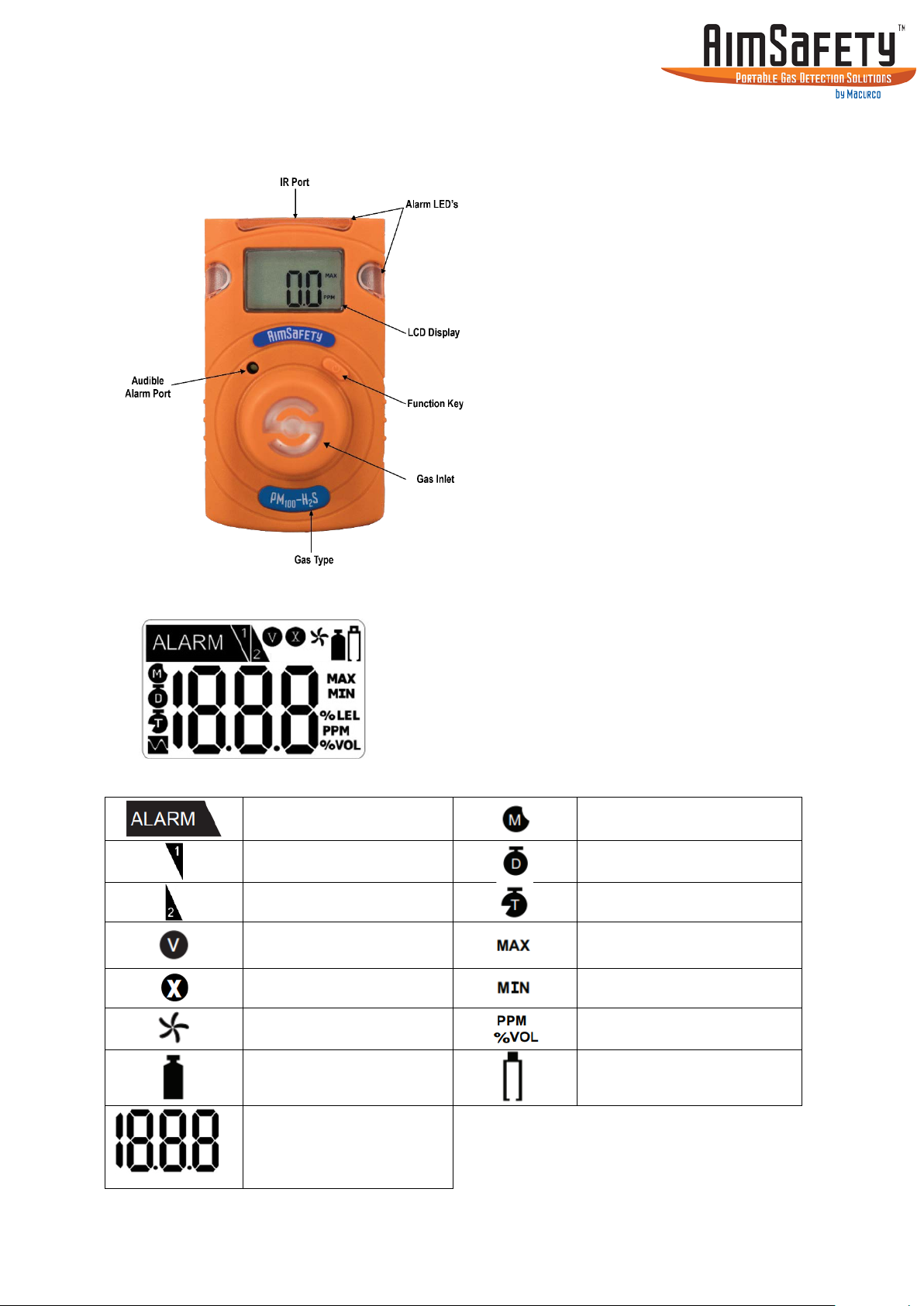
3.1. Monitor Overview
PM
User’s Manual
100
3.2. Display Overview
LCD display symbols
Alarm condition
Low Alarm
High Alarm
Stabilization Failure
Remaining Month(s)
Remaining Day
Remaining Hour(s)
Max Peak Value
Min Peak Value
Fresh Air Calibration Icon
Span Calibration Icon
Real-Time Gas Readings
Or Numerical Values
Or Abbreviated Text
Measurement Unit
Lifetime less than 30 days
Or Low Battery
Page 7
PM
Page 7
CAUTION: Before use, check the activate by date on the box. Do not use the
User’s Manual
100
4. Activation
monitor if the activate by date has passed.
Note: The PM
monitor is designed to operate continuously for the life of the instrument
100
and cannot be turned off once activated.
4.1. Activating the Monitor
To activate the monitor, press and hold the [Function key] for 3 seconds. While the key is
depressed, a 3-second count-up timer will be displayed. Once the counter reaches three
(3), release the [Function key].
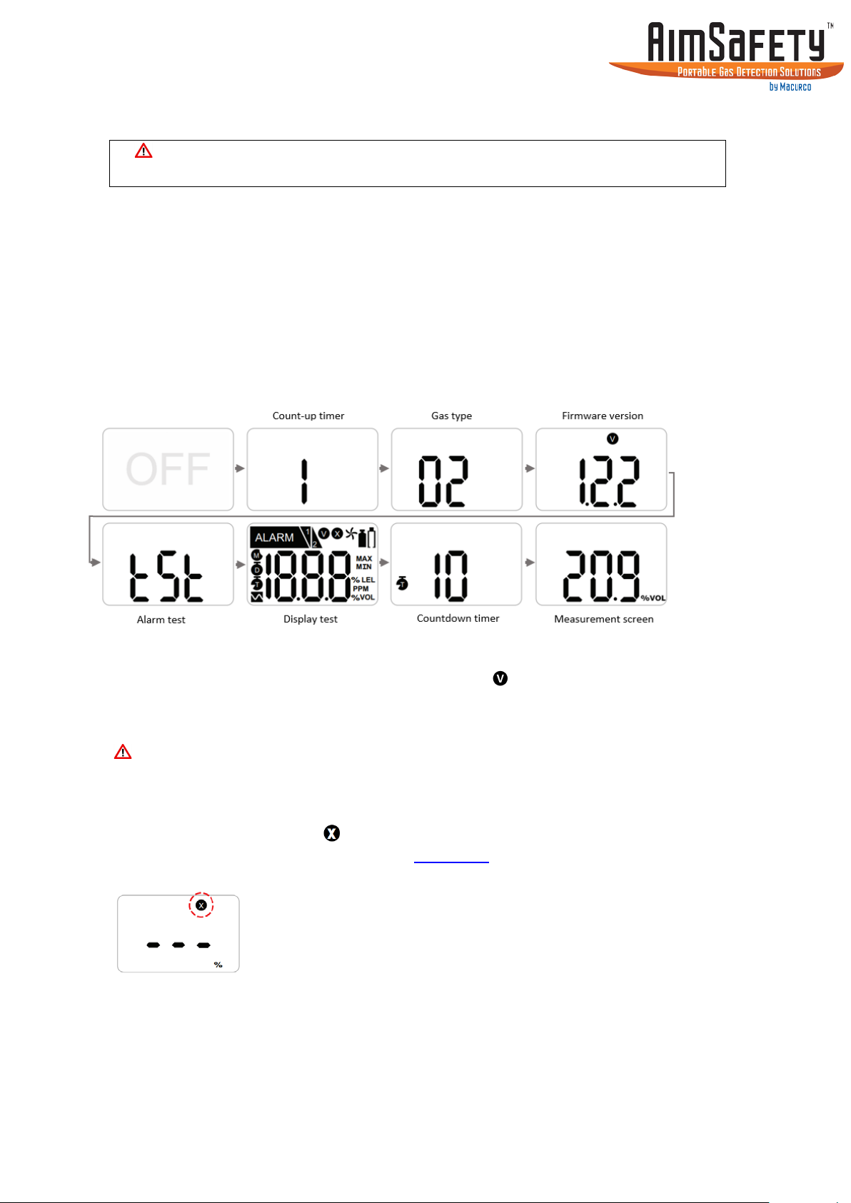
The monitor will perform the following startup sequence.
The unit will display the gas type, firmware version, display/alarm test, followed by a 10-
is complete, the monitor defaults second stabilization countdown. Once the countdown
to Measurement mode, displaying the current gas readings and the icon.
Sensor readings may drift during shipping. All newly purchased monitors should be
bump tested to a known concentration of gas before use.
If sensor stabilization fails, the icon will appear on the display and no gas concentrations
will be displayed. Perform a calibration (see Calibration) or contact AimSafety for more
information.
Page 8

PM
Page 8
Month
Day
Hour
O2
H2S
CO
User’s Manual
100
5. User Interface
The PM
• Measuring Mode – Standard display operation with real-time gas readings always
displayed
• Basic Mode – Remaining sensor life will be displayed unless an alarm condition is
detected
Gas concentrations are displayed with gas specific units of measure based on the type of
gas to be detect. Oxygen concentrations are displayed in percent by volume (%Vol) and
toxic concentrations are displayed in parts per million. (PPM)
5.1. Display Modes
Measuring Mode is the default mode. Once the monitor is activated the meter will
has two operational modes:
100
continually display measure gas concentrations in real-time.
Basic Mode is an optional mode where the remaining sensor life will be displayed if the
detected gas levels are below the alarm threshold. The monitor will display the active gas
reading only after an alarm threshold has been exceeded. Basic mode can only be enabled
using the PM Link and software, or the Bump Test-Calibration Station.
Page 9

PM
Page 9
User’s Manual
100
5.2. Menu Screens
From the Measurement screen, pressing the [Function key] will step to the next screen.
Note: If you do not press the [Function key] within 10 seconds, the display reverts to
the main screen.
Stealth Mode Press the [Function key] to advance to Stealth Mode (if enabled). Stealth is an
optional setting that disables all audible, vibrating alarms and alarm LEDs.
When Stealth is enabled, an “StL” screen is added to the menu to indicate that
the audible and vibrating alarms are disabled. The display alarm flags are the
only indication of an alarm condition.
Peak MIN Press the [Function key] to advance to Peak MIN indicated by the MIN icon on
the display (O2 only), with the numerical value displayed. The Peak MIN is the
lowest concentration of oxygen that the sensor has detected since the peaks
were last cleared.
Peak MAX Press the [Function key] to advance to Peak MAX indicated by the MAX icon on
the display, with the peak max concentration displayed. The Peak MAX is the
highest concentration of gas that the sensor has detected since the peaks were
last cleared.
Clear Peaks Press the [Function key] to advance to Clear Peaks indicated by “CLr” on the
display. To clear the peaks, press and hold the [Function key] for three seconds.
The unit will beep once, and the MIN/MAX icon will turn off.
Remaining Life Press the [Function key] to advance to Remaining Life indicated by one of three
icons on the display. Remaining life is the amount of time left on the monitor
before End-of-Life. The remaining life is displayed in months, days, or hours as
indicated by the display icons.
Alarm 1 Press the [Function key] to advance to Alarm Set Point 1 indicated by the 1 flag
on the display. This is the first (low for O2) set point that activates the monitors
alarms. The unit will store this alarm data in event logging.
Alarm 2 Press the [Function key] to advance to Alarm Set Point 2 indicated by the 2 flag
on the display. This is the second (high for O2) set point that activates the
monitors alarms. The unit will store this alarm data in event logging.
Firmware Press the [Function key] to advance to Firmware Version indicated by the V icon
on the display. This is the current firmware version that is loaded into the
monitor.
Calibration Press the [Function key] to advance to Calibration indicated by the calibration
cylinder bottle icon on the display. The calibration gas concentration will be
displayed. See Calibration for more information on monitor calibration.
Page 10

Page 10
Menu Flow Chart
Measurement screen
Stealth (Optional)
Peaks MIN (O2 only)
Peaks MAX
Clear Peaks
Remaining Life
Alarm Set Point 1
Alarm Set Point 2
Firmware Version
Calibration
PM
User’s Manual
100
5.3. Alarm and Alerts
When the gas concentration exceeds the monitor’s alarm set points the alarms will
activate: The display will show the Alarm icon, the Alarm 1 or Alarm 2 icon, and the gas
level. The monitor will vibrate, the buzzer will sound, and the LEDs will flash.
Immediately exit the area to clean air. The alarms will clear once the gas concentrations go
below the alarm set points.
Page 11

Page 11
Alarm and Alert indication chart
Alarm
Alarm Standard
LCD Display
Alarm and Vibration Display
concentration
concentration
Life
remaining
End-Of-Life in less than 30
days
Sensor test
failure
PM
User’s Manual
100
Low Alarm
High Alarm
Exceeds 1st
Alarm set point
Exceeds 2nd
Alarm set point
Below 30 days
End-Of-Life Past 24 months
Test failure
Battery Low
Or calibration
Low battery
power
Icons & gas
Icons & gas
Icon & buzzer
Icon
Monitor has reached End-OfLife. (Replace the unit with a
new PM
100
)
Perform a successful
calibration to clear
Replace the unit with a new
PM
100
Bump test Bump test due
Calibration Calibration due
Calibration
Failed
Failed calibration
Perform a successful bump
test to clear
Perform a successful
calibration to clear
Perform a successful
calibration to clear
Page 12

PM
Page 12
Gas Type
CO
H2S
O2
Low Alarm
35 ppm
10 ppm
19.5%
High Alarm
100 ppm
15 ppm
23.5%
End
LCD
Test
Buzzer
LED
Buzzer
Display
Alarm 1
Alarm 2
User’s Manual
100
5.4. Default Alarm Set Points
Note: Alarm levels can only be changed using the PM Link and software, or the Bump Test-
Calibration Station.
5.5. Self-Test Reminder
The Self-Test reminder option can be enabled using the PM Link and software or the Bump
Test-Calibration Station. The Self-Test reminder can be configured to n/a (Off) or between 8
hours to 20 hours. The default configuration is set to “Off”, no Self-Test reminder will be
displayed.
When enabled, the monitor will prompt the user to perform the test by displaying “StS” on
the display when the test is due.
• To activate the test, press the [Function key].
The unit will then perform the following:
• Buzzer test
• LED test
• Vibration
• LCD test
• Display Alarm set point 1
• Display Alarm set point 2
• End
The user is required to ensure that all the tests pass successfully and that the alarm values
are set to the proper levels.
Do not use the monitor if any of the tests fail or if the alarm values are incorrect
Page 13

PM
Page 13
Bump Test Due
Apply Gas
Gas Detected
Test Passed
Remove Gas
Main Screen
User’s Manual
100
5.6. Bump Test Reminder
The Bump Test due reminder option can be enabled using the PM Link and software or the
Bump Test-Calibration Station. The Bump Test reminder can be configured from n/a (Off) to
365 days. The default configuration is set to “Off”, no Bump Test reminder will be displayed.
When enabled, the monitor will prompt the user to perform the test by displaying “btS” on
the display when the test is due.
• Ensure that the sensor is reading zero (or 20.9% for Oxygen)
• Attach the calibration (cal) cap on top of the sensor inlet
• Connect the hose from the gas regulator of the calibration gas cylinder to the cal
cap. Ensure the calibration gas and gas concentrations match the sensor installed in
the instrument
• To activate the test, press and hold the [Function key] for 3 seconds and “tSt” will be
displayed
• Turn on the gas regulator
• Once gas is detected, “GAS” will be displayed
• After the test is passed, “SUC” and the icon will appear on the display followed by
the alarm notification
• Once the test has passed, remove the calibration cap and turn off the calibration
gas
• Allow a few minutes for the gas to dissipate
• After the gas has dissipated from the sensor, clear the sensor Peak values
Check the calibration gas concentrations, cylinder expiration date, and the monitor gas
settings and re-test the unit. Or perform a full calibration as defined in the calibration
section.
Clear Alarm Flags
If the sensor fails the bump test, an “FA” message with the icon will briefly display, then
the “bts” message will resume.
If the Bump Test fails, do not use the monitor until a successful Bump Test or
Calibration is performed.
Page 14
PM
Page 14
User’s Manual
100
6. Bump Test
A bump test is used to test that the monitor is working properly. During a bump test, a
known concentration of gas is applied to the sensor to verify that the sensor responds to
the gas, and the alarms activate. This is the only way to effectively confirm that all
characteristics of the monitor and the sensor are working correctly.
A bump test should be conducted before each day’s use.
Ensure that you are in a clean environment before performing a Bump Test.
The monitor must be calibrated if it fails a Bump Test.
To perform a manual Bump Test: (without the Bump Test Reminder active)
• Ensure that the sensor is reading zero (or 20.9% for Oxygen)
• Attach the calibration (cal) cap on top of the sensor inlet
• Connect the hose from the gas regulator of the calibration gas bottle to the cal cap.
Ensure the calibration gas and gas concentrations matches the sensor installed in
the instrument.
• Access the Calibration menu (see section Accessing the Calibration Menu)
• “CAL” and the icon are displayed.
• Press the [Function key] once and “CAL” and the icon will appear.
• Press the [Function key] again “btS” will be displayed.
• Press and hold the [Function key] for 5 seconds and “tSt” will be displayed
• Turn on the gas regulator
• Once gas is detected, “GAS” will be displayed
• After the test is passed, “SUC” and the icon will appear on the display followed by
the alarm notification and “btS”
• Once the test has passed, remove the calibration cap and turn off the calibration
gas. The monitor will default to the main screen after 20 seconds or you can
manually exit the calibration menu (see Exiting the Calibration Menu)
• Allow a few minutes for the gas to dissipate
• After the gas has dissipated from the sensor, clear the sensor Peak values (See Clear
Peaks)
Page 15

PM
Page 15
Test Failed
Bump Test
Apply Gas
Gas Detected
Test Passed
Remove Gas
Main Screen
User’s Manual
100
Clear Alarm Flags
The unit is now ready for use. Otherwise do not use the monitor until the reason for the
discrepancy for the test has been determined and corrected.
If the sensor fails the bump test, an “FA” message with the icon will briefly display
Check the calibration gas concentrations, cylinder expiration date, and the monitor gas
settings and re-test the unit. Or perform a full calibration as defined in the calibration
section.
If the Bump Test fails, do not use the monitor until a successful Bump Test or
Calibration is performed.
Page 16

PM
Page 16
Fresh Air Calibration
Span Calibration
Bump Test
Exit
User’s Manual
100
7. Calibration
Calibration is the process of adjusting the sensor’s response by using a specific
concentration of calibration gas. Sensors will drift for a variety of reasons, so it is important
to perform a full calibration periodically to ensure that the sensors response to the target
gas are accurate. A full calibration consists of two points, a Fresh Air Calibration and a Span
Calibration.
Fresh Air Calibration adjusts the zero offset of the toxic sensor or sets the oxygen sensor to
20.9% Vol.
Span Calibration adjusts the sensors response to gas to account for sensor drift. It is
recommended to perform a Fresh Air Calibration prior to a Span Calibration.
CAUTION: For O
shipment. Once received, calibration should be performed monthly (or quarterly)
depending on frequency of use.
All alarms are muted during calibration.
units: Initial calibration is performed on all devices prior to
2
7.1. Accessing the Calibration Menu
To access the calibration menu:
• Press the [Function key] to navigate to the Calibration screen.
• While the Calibration screen is displayed, press and hold down the [Function key]
for 5 seconds to access the Calibration mode.
Once the Calibration menu is accessed, “CAL” and the icon will be displayed. Calibration
menu has four options:
• Fresh Air Calibration
• Span Calibration
• Bump Te st
• ESC – Exit Calibration Mode
7.2. Exiting the Calibration Menu
Press the [Function key] until “ESC” is displayed on the screen. Press and hold the [Function
key] for 5 seconds, the monitor will return to the Calibration screen. Press the [Function
key] again and the unit will return to the Measurement screen.
Note: If you do not press the [Function key] within 20 seconds, the display reverts to the
main screen.
Page 17

Page 17
7.3. Fresh Air Calibration
Fresh Air Calibration must be performed in a clean environment that is free from
other gases (calibration is assumed to be performed in an environment with an
Oxygen concentration of 20.9% Vol.). Fresh Air Calibration should not be performed in
a confined space.
To perform a Fresh Air Calibration:
• Access the Calibration menu.
• “CAL” and the
• Press and hold the [Function key] for 5 seconds to start the Fresh Air Calibration.
• When the calibration starts, a countdown (starting at 10) will appear on the screen.
Note: Press the [Function key] during the 10 second countdown to abort.
• Once the countdown is complete “CAL”, the and icons will be displayed
indicating a successful Fresh Air Calibration.
Note: If you do not press the [Function key] within 20 seconds, the display reverts to
the main screen.
icon will be displayed.
PM
User’s Manual
100
icon will appear on the display. If this continues, please contact If calibration fails, the
the sales representative or AimSafety Technical Support.
Page 18

Page 18
7.4. Span Calibration
Gas Type
O2
CO
H2S
Concentration
18.0% Vol
100 ppm
25 ppm
When performing a Span Calibration only use certified calibration gas at the required
concentration level. Do not use expired calibration gas.
To perform a Span Calibration:
• Access the Calibration menu.
• “CAL” and the
• Press the [Function key] once and “CAL” and the icon will appear.
• Attach the calibration (cal) cap on top of the sensor inlet.
• Connect the hose from the gas regulator of the calibration gas bottle to the cal cap
• Press and hold the [Function key] for 5 seconds to start the Span Calibration.
• When the calibration starts, a 90-second countdown displays.
Note: The countdown is only 60 seconds for O2
• Turn on the calibration gas.
• Once completed, the icon and the current gas measurement readings will appear
on the display.
• The device will return to Measuring mode.
• Turn off the calibration gas and remove the calibration cap.
• Clear the Peak values for the sensor. (See Clear Peaks)
All alarms are muted for approximately 10 minutes after a successful span calibration.
PM
User’s Manual
100
icon are displayed.
If the calibration fails, the and icons and CAL will cycle on the display until a
successful calibration is performed. Contact the sales representatives or AimSafety
Technical Support if a successful calibration cannot be performed.
Default Calibration gas concentrations.
Default calibration gas concentrations can be changed using the PM Link and PC software
or with the Bump Test – Calibration Station.
Page 19

PM
Page 19
User’s Manual
100
8. Event Log
Event logging occurs anytime that an alarm condition is met. Once an alarm condition is
met the monitor will automatically save that event in the memory. The monitor can store
up to 30 events, once more than 30 events are stored, any new events overwrite the oldest
ones. The stored log events can be downloaded using the PM Link and PC software or or
with the Bump Test – Calibration Station.
Event log captures the following monitor information:
• Product Name
• Serial number
• Log Type
• Firmware version
• Alarm setpoints
• Life remaining
• Total Number of Events
• Duration of Events
• Zero Calibration date
• Span Calibration date
Each alarm event records the followings event details:
• Date
• Time
• Duration
• Sensor Readings
• Alarm Type
See the PM Link PC software and Bump Test-Calibration Station manual for more
information on Event Log.
Page 20

PM
Page 20
User’s Manual
100
9. Maintenance and Cleaning
The PM
turned off once activated. It is important to avoid the following activities as they will
deplete the battery lifetime to less than 24 months.
1. Frequent or prolonged alarm activation. (Normal Alarm use: 2 minutes per day)
2. Unnecessary [Function key] operation
3. Connecting the PM Link frequently (except for regular bump testing/calibration)
9.1. Maintenance
Do not disassemble unit or attempt to repair or modify any component of this instrument.
This instrument contains no user serviceable parts, and substitution of components may
impair intrinsic safety which may adversely affect product performance.
9.2. Cleaning
CAUTION: Do not attempt to clean the instrument in a hazardous environment. Cleaning
with a dry cloth may generate a static charge and result in an explosion if located in a
hazardous environment.
Occasionally clean the monitor with a soft cloth. Do not use detergents or chemicals. If
necessary, use a damp cloth (water only). It is recommended to install the Calibration Cap
before cleaning the monitor housing, to keep dirt, dust, or moisture away from the sensor
openings and to help keep the sensor filter clean.
Visually inspect the monitor and the IR port window on the top of the monitor. Wipe it with
a soft cloth as needed.
monitor is designed to operate continuously for the life of the unit and cannot be
100
Page 21

PM
Page 21
IECEx:
Ex ia IIC T4 Ga
1: Explosion protected
5: Equipment protection level
Class I, Zone 0, AEx ia IIC T4 Ga
Ed. 3; UL 913, Ed. 8; UL 60079-0, Ed. 6; UL 60079-11, Ed. 6
ATEX:
2198 II 1 G Ex ia IIC T4 Ga IP67
Directive 2014/34/EU
KCS:
Ex ia IIC T4
KTL 16-KA2BO-0457
INMETRO
Ex ia IIC T4 Ga
Standards:
The electrical apparatus and any acceptable variations to it specified in the
EN 60079-11: 2012
Compliance:
Electromagnetic Compatibility Directive 2014/30/EU
Manufacturing
Approval:
The monitor manufacturer is certified compliant with ISO 9001:2000
provisions
User’s Manual
100
10. Disposal
The PM
instrument, follow local solid waste disposal regulations.
is designed to be discarded 2 years after activation. To properly dispose of the
100
11. Certificates
The PM
meets or exceeds the following certification standards.
100
Class I, Division 1, Groups A, B, C, D, T4
C22.2 No. 60079-0:2015; C22.2 No. 60079-11:2014;
C22.2 No. 61010-1-12:2010; UL 61010-1,
KRH 17 ATEX 0013
BVC16.5919
schedule of this certificate and the identified documents, was found to comply
with the following standards:
IEC 60079-0: 2011 Ed. 6
IEC 60079-11: 2011 Ed 6
UL 61010-1, Ed. 3
UL 913, Ed. 8
UL 60079-0, Ed. 6
UL 60079-11, Ed. 6
C22.2 No. 60079-0:2015
C22.2 No. 60079-11:2014
C22.2 No. 61010-1-12:2012
EN 60079-0: 2012+A11:2013
2: Protection Concept
3: Gas Group
4: Temperature Classification
Page 22

Page 22
12. Limited Warranty
AimSafety warrants this product will be free from defective materials and
workmanship for a period of two (2) years from date of manufacture, provided it is
maintained and used in accordance with AimSafety instructions and/or
recommendations. If any component becomes defective during the warranty
period, it will be replaced or repaired free of charge, if the unit is returned in
accordance with the instructions below. This warranty does not apply to units that
have been altered or had repair attempted, or that have been subjected to abuse,
accidental or otherwise. The above warranty is in lieu of all other express
warranties, obligations or liabilities. THE IMPLIED WARRANTIES OF
MERCHANTABILITY AND FITNESS FOR PARTICULAR PURPOSE ARE LIMITED TO A
PERIOD OF TWO (2) YEARS FROM THE PURCHASE DATE. AimSafety shall not be
liable for any incidental or consequential damages for breach of this or any other
warranty, express or implied, arising out of or related to the use of said gas monitor.
Manufacturer or its agent’s liability shall be limited to replacement or repair as set
forth above. Buyer’s sole and exclusive remedies are return of the goods and
repayment of the price, or repair and replacement of non-conforming goods or
parts.
Warranty Procedure
Contact the local AimSafety authorized reseller or AimSafety Technical Support to
obtain a Return Materials Authorization (RMA). An RMA requires the following
information:
• Company name, contact name, phone number, and email address
• Description and quantity of items to be returned
• Equipment serial number(s)
• Reason for return
No returns shall be accepted without an AimSafety RMA. Any returns received
without an RMA will be rejected and returned to the sender.
PM
User’s Manual
100
13. Contact Information
Technical Support
Monday through Friday, 8:00AM to 5:00PM Central (US) Time
Email: support@aimsafety.com
Phone (toll-free): 1-844-325-3050
World Headquarters
3601 North St. Paul Avenue
Sioux Falls, SD 57104 USA
Phone: 1-877-367-7891
Fax: 1-605-951-9616
E-mail: info@aimsafety.com
Web Site: www.aimsafety.com
 Loading...