

Page 1
AimSafety
Menu Flow Chart
PM
Personal Single Gas Monitor
Quick Start Guide
Please refer to the PM
User’s Manual for additional
100
product information and features.
www.aimsafety.com
AimSafety Contact Information
Technical Suppor t
Monday - Friday 8:00 AM to 5:00 PM Central (US) time.
Email: support@aimsafet y.com
Phone (toll-free): 1-844-325-3050
World Headquarters
3601 North St. Paul Avenue
Sioux Falls, S D 57104 USA
Phone: 1-877-367-7891
Fax: 1-605-951-9616
100
P/N: 34-2900-0211-0 Rev.:A
WARNINGS
Any unauthorized attempt to repair or modify the product, or any other cause of
damage beyond the range of the intend ed use, including damage by fire, lightning,
or other hazard, voids liability of the manufacturer.
Activate this product only if sensor, visual, detection, and audible cover are clear
from contaminants such as dirt and debris that could block the area where gas is
to be detected.
Do not clean and rub th e LCD screen of the products with a dry cloth or hands in
hazardous environm ent to prevent static electricity.
Perform cleaning and maintenance of the products in fresh air that is free of
hazardous gases.
Test the response of the sensor regularly with a gas concentration exceedi ng the
alarm set point.
Test LED, audio, and vibration manually.
Gas concentration measurements by the sensor can vary based on the
environment (temperature, pressur e and humidity). Therefore, calibra tion of
PM
100
actual use.
If the temperature changes sharply during use of the device (e.g., indoors vs
outdoors), the value of the measured gas concentration can suddenly change.
Please use the PM
Severe vibration or shock to the device may cause a sudden reading change.
Please use PM
shock to PM
All alarm values is set based on the alarm standard tha t is required by
international standards. Therefore, alarm values should be changed onl y under
the responsibility and approval of the administration of the work site where the
instrument is used.
Use IR communications in the safety z one which is free of hazardous g ases.
Do not attempt to replace the battery and se nsor as PM
disposable. Changing the battery and sensor may impair intrinsic safety and the
attempt will void warranty.
should be performed in the same (or similar) envi ronment of the device’s
after the gas concentration value has stabilized.
100
after the value of gas concentration has stabilized. Excessive
100
can cause the device and/or sensor to malfunction.
100
is designed to be
100
CAUTIONS
Before operating this device, please read the manual carefully.
This device is not a measurement device, but a gas detector.
If calibration and self-test fails continuously, please do not use the device.
For the O
Before use, please check the activation date, and if the activation date has past,
Clean detectors with a soft cloth and do not use chemical substances for
To maintain a 24-month lifetime, avoid the below activities except in
View a serial number on the label at the back side of the device. (ex,
ex) SG 01 01 001 2017(Year) 01(Months) 01(Day) 001(Manufacture Order)
detector, perform calibration every 30 days in the fresh air
2
environment.
please do not use the device.
cleaning.
necessary cases to check events(Max/Min), lifetime/concentration, and alarm
set points. Otherwis e, the frequent use of the button will deplete the battery
lifetime less than 24 months.
1. Push the button frequently without valid reasons.
2. Frequent alarm operation or alarms are remained for a long time.
*Normal Alarm Use: 1 time and 2 minutes per day.
3. Connect with the PM Link freq uently except the bump testing.
20170101)
1. The serial number indicat es below.
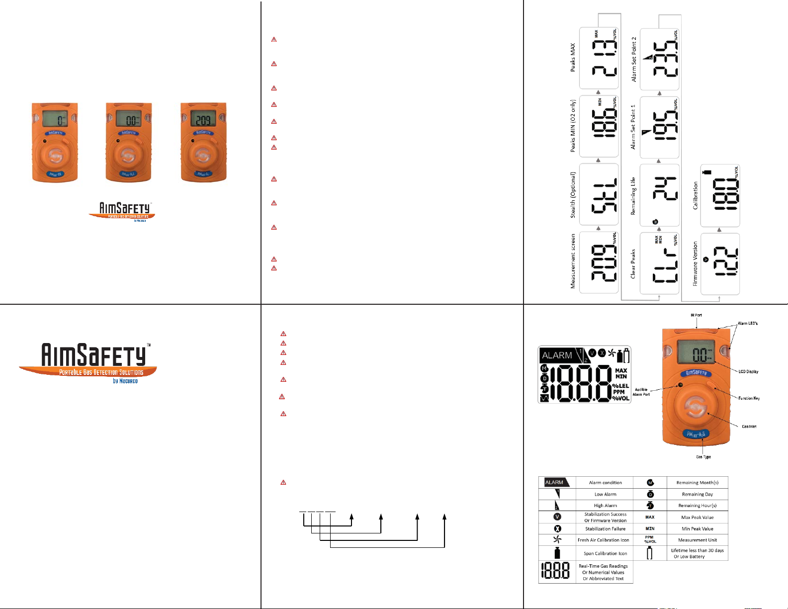
Product Overview Monitor
Display
Display symbols
Page 2
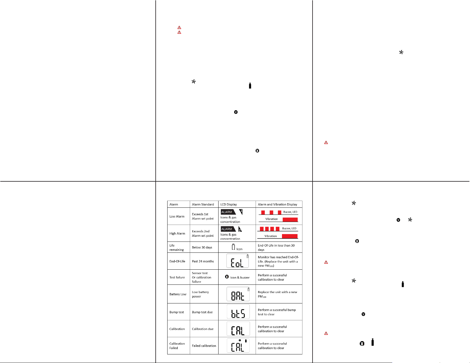
Alarm and Alert indication chart
Activation
Activating the Monitor
To activate the monitor, press and hold the [Function key] for 3 seconds. While the
key is depressed, a 3-second count-up timer will be displayed. Once the counter
reaches three (3), release the [Function key].
The monitor will perform the following startup sequence.
The unit will display the gas type, firmware version, display/alarm test, followed by a
10-second stabilization countdown. Once the countdown is complete, the monitor
defaults to Measure- ment mode, displaying the current gas readings and the icon.
Sensor readings may dri ft during shippi n g. All newly purchased monitors should be
bump tested to a known concentration of gas before use.
User Interface
Display Modes
Measuring M ode is the d efaul t mode. Once the m onitor i s acti vated the me ter wil l
continually display measured gas concentrations in real-time.
Basic Mode is an optional mode where the remaining sensor life will be
displayed if the detected gas levels are below the alarm threshold. The monitor will
display the active gas reading only after an alarm threshold has been exceeded.
Basic mode can only be enabled using the PM Link and sof tware , or th e Bump TestCalibration Station.
Menu Screens
From the Display mode screen, pressing the [Function key] will step to the next
screen. Note: If you do not press the [Function key] within 10 seconds, the display
reverts to the main screen.
Stealth Mode - Press the [Function key] to advance to Stealth Mode (if enabled).
Stealth is an optional setting that disables all audible, vibrating alarms and alarm
LEDs. When Stealth is enab l ed, an “StL” screen is added to the menu to indicate
that the audible, visual, and vibrating alarms are silenced.
User Interface Continued
Peak MIN - Press the [Function key] to advance to Peak MIN indicated by the MIN
icon on the display (O
lowest concent ration of oxy ge n that the sensor has d etected since the peaks were last
cleared.
Peak MAX - Pr es s th e [ Function key] to advance to Peak MAX indicated by the MAX
icon on the display, with the peak max concentration displayed. The Peak MAX is the
highest concentration of gas that the sensor has detected since the peaks were last
cleared.
Clear Peaks - Press the [Function key] to advance to Clear Peaks indicated by “CLr”
on the display. To clear the peaks, press and hold the [Function key] for three seconds.
The unit will beep once, and the MIN/MAX icon will turn off.
Remaining Life - Press the [Function key] to advance to Remaining Life indicated by
one of three icons on the display. Remaining life is the amount of time left on the
monitor before End-of-Life. The remaining life is displayed in months, days, or hours
as indicated by the display icons.
Alarm 1 - Press the [Function key] to advance to Alarm Set Point 1 indicated by the 1
flag on the display. This is the first (low for O
alarms. The unit will store thi s alarm data in eve nt logging.
Alarm 2 - Press the [Function key] to advance to Alarm Set Point 2 indicated by the 2
flag on the display. This is the second (high for O
alarms. The unit will store thi s alarm data in eve nt logging.
Firmware - Press the [Function key] to advance to Firmware Version indicated by the
V icon on the display. This is the current firmware version that is loaded into the
monitor.
Calibration - Press the [Function key] to advance to Calibration indicated by the
calibration cylinder bottle icon on the display. The calibration gas concentration will be
displayed. See Calibration for more information on monitor calibration.
only), with the numerical value displayed. The Peak MIN is the
2
) set point that activates the monitors
2
) set point that activates the monitors
2
Bump Test
A bump test should be conducted before each day’s use.
Ensure that you are in a clean environment before performing a Bump
Test. The monitor must be calibrated if it fails a Bump Test.
To perform a manual Bump Test: (without the Bump Test Reminder active)
• Ensure that the sensor is reading zero (or 20.9% for Oxygen)
• Attach the calibration (cal) cap on top of the sensor inlet
• Connect the hose from the gas regulator of the calibration gas bottle to the cal cap.
Ensure the calibration gas and gas concentrations matches the sensor installed in the
instrument.
• Access the Calibration menu (see section “Accessing Calibration Menu”)
• “CAL” and the icon are displayed.
• Press the [Function key] once and “CAL” and the icon will appear.
• Press the [Function key] again “btS” will be displayed.
• Press and hold the [Function key] for 5 seconds and “tSt” will be displayed
• Turn on the gas regulator
• Once gas is detected, “GAS” will be displayed
• After the test is passed, “SUC” and the icon will appear on the display followed by
the alarm noti fication and “btS”
• Once the test has pass ed, remove the cal i bration cap and t urn off the calibration gas.
The monitor will default to the main screen after 20 seconds or you can manually exit
the calibration menu (see Exiting the Calibration Menu)
• Allow a few minutes for the gas to dissipate
• After the gas has dissipated from the sensor, clear the sensor Peak values
If the sensor fails the bump test, an “FA” message with the icon will briefly display
Calibration
To access the calibration menu:
• Press the [Function key] to navigate to the Calibration screen.
• While the Calibration screen is displayed, press and hold down the [Function key] for 5
seconds to access the Calibration mode.
Once the Calibr ation menu is acc essed, “CAL” an d the icon will be displayed. Calibration
menu has four opt i ons:
• Fresh Air Calibration
• Spa n Cal ibration
• Bump Test
• ESC – Exit Calibration Mode
To exit the calibration menu:
• Press the [Function key] until ESC is displayed.
• Press and hold down the [Function] key for 5 seconds to access the Calibration mode.
• Press the [Function] key again to return to the Measurement screen.
Note:
If you don’t press the [Function] key within 20 seconds, the display reverts to the main
screen.
Fresh Air Calibration
Fresh Air Calibration must be performed in a clean environment that is free
from other gases (calibration is assumed to be performed in an environment
with an Oxygen concentration of 20.9% Vol.). Fresh Air Calibration should not
be performed in a confined space.
To Perform a Fresh Air calibration
• Access the Calibration menu
• “CAL” and the icon will be displayed.
• Press and hold the [Function] key to start the Fresh Air calibration.
• A ten second countdown will appear on the screen.
Note: press the [Function] key any time during the countdown to abort.
• Once the countdown is complete “CAL”, the and icons will be displayed
indicating a successful Fresh Air Calibration.
Note: If you do not press the [Function] key within 20 seconds, the display reverts to
the main screen.
If Calibration fails, the icon will appear on the display. If this continues, please contact
the sales representative or AimSafety Technical Support.
Span Calibration
When performing a Span Calibration only use certified calibration gas at the
required concentration level. Do not use expired calibration gas.
To perform a Span calibration
• Access the Calibration menu
• “CAL” and the icon will be displayed.
• Press the [Function] key once and CAL and the icon will appear.
• Attach the calibration (cal) cap on top of the sensor inlet.
• Connect the hos e from the gas regulator of the calibration gas bottle to the cal cap
• Press and hole the [Function] key for 5 seconds to start the Span calibration.
• When calibration starts, a 90-second countdown displays.
Note: The countdown is only 60 seconds for 0
• Turn on the calibration gas.
• Once completed, the icon and the current gas measurement readings are displayed.
• The device will return to Measuring mode.
• Turn off the calibration gas and remove the calibration cap.
• Clear the peak values for the sensor.
All alarms are muted for approximately 10 minutes after a successful Span
calibration.
If the calibration fails, the and icons and CAL will cycle on the display until a successful
calibration is performed. If calibration continues to fail, contact the sales representatives or
AimSafety Technical support.
2.
 Loading...