

Page 1
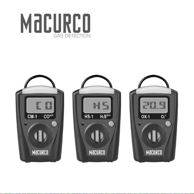
Macurco
HS-1 Hydrogen Sulfide (H
User Instructions
™ Single-Gas Monitor Series, CM-1 Carbon Monoxide (CO),
2S), OX-1 Oxygen (O2)
Important: Keep these User Instructions for reference
Page 2

2
Page 3

TABLE OF CONTENTS
GENERAL SAFETY INFORMATION 4
Intended Use 4
List of Warnings and Cautions 4
USE INSTRUCTIONS AND LIMITATIONS 6
Use For 6
Do Not Use For 6
General Description 6
SPECIFICATIONS 9
OPERATING INSTRUCTIONS 11
Activating the Detector 11
Display Readings 12
Normal Operating Mode 12
2S and CO Models 12
H
2 Model 12
O
Performing Self-test 13
Viewing Peak Levels 13
Time Remaining Indicator 14
End of Life Indicator 14
Alarms 14
Viewing Alarm Set Points 15
Low Alarm 15
High Alarm 15
Over Range Alarm 15
3
Page 4

Low Battery Alarm 15
Alarm Mode Table 16
Calibration Verification Test and Calibration 16
Performing a Calibration Verification Test
(Bump Test) (CO & H
Performing a Calibration (O
2S Models Only) 17
2 Model Only) 18
MAINTENANCE 19
Cleaning 19
Disposal 19
WARRANTY 20
GENERAL SAFETY INFORMATION
Intended Use
The Macurco™ Single-Gas Monitor Series is designed to continuously monitor the
ambient environment and notify the user if the level of the target gas reaches the alarm
set point for the monitor. The Macurco™ Single-Gas Monitor is designed to operate for 2
years and then be disposed of according to local regulations. The Macurco Single-Gas
Monitor is a single gas detector that is available in three versions to monitor either Carbon
Monoxide (CO), Hydrogen Sulfide (H
2S) or Oxygen (O2).
List of Warnings and Cautions within these User Instructions
! WARNING
Each person using this equipment must read and understand the information in these User
Instructions before use. Use of this equipment by untrained or unqualified persons, or use that is
not in accordance with these User Instructions, may adversely affect product performance and
result in sickness or death.
4
Page 5

This instrument helps monitor for the presence and concentration level of certain specified
airborne gases. Misuse may produce an inaccurate reading, which means that higher levels of the
gas being monitored may be present and could result in overexposure and cause sickness or
death. With oxygen sensor installed, misuse may produce an inaccurate reading where lower or
higher levels of oxygen may be present and cause sickness or death. For proper use, see
supervisor or User Instructions, or call Macurco Technical Service at 1-877-367-7891.
Use only for monitoring the gas which the sensor and instrument are designed to monitor. Failure
to do so may result in exposures to gases not detectable and cause sickness or death. For proper
use, see supervisor or User Instructions, or call Macurco Technical Service at 1-877-367-7891.
Each time a self-test is performed, it activates the audible, vibratory and visual alarms. If the self-
test fails, or all the alarms do not activate, do not use. Failure to do so may adversely affect
product performance and result in sickness or death.
Immediately exit any environment that causes an alarm condition on the monitor. Failure to do so
may result in sickness or death.
Do not cover or obstruct display, audible alarm opening or visual alarm cover. Doing so may
adversely affect product performance and result in sickness or death.
Vibrator and LCD may not function effectively below –4 °F (–20 °C). Using the instrument below
this temperature may adversely affect product performance and result in sickness or death.
The following steps must be performed when performing a calibration (O
verification test (CO and H
2S models) to ensure proper performance of the detector. Failure to do
2 model) or calibration
so may adversely affect product performance and result in sickness or death.
When performing a calibration or calibration verification test (bump test) only use certified
calibration gas at the required concentration level. Do not use expired calibration gas.
A calibration verification test (bump test) should be performed before initial and each use.
If the instrument cannot be calibrated (O
2 model) or calibration verification test (CO and H2S
models) is not within ± 15% of the calibration gas concentration, do not use until the reason
can be determined and corrected.
Do not cover or obstruct display, audible alarm opening or visual alarm cover.
Ensure sensor inlet is unobstructed and is free of debris.
5
Page 6

Insure calibration hood is removed prior to use.
Do not attempt to clean the instrument by rubbing with a dry cloth. Cleaning with a dry cloth may
generate a static charge and result in an explosion if located in a hazardous environment.
Do not disassemble unit or attempt to repair or modify any component of this instrument. This
instrument contains no user serviceable parts, and substitution of components may impair intrinsic
safety which may adversely affect product performance and result in sickness or death.
USE INSTRUCTIONS AND LIMITATIONS
! WARNING
Each person using this equipment must read and understand the information in these User
Instructions before use. Use of this equipment by untrained or unqualified persons, or use that is not
in accordance with these User Instructions, may adversely affect product performance and result in
sickness or death.
Use For
Monitoring for, either Carbon Monoxide (CO), Hydrogen Sulfide (H2S) or Oxygen (O2).
Do Not Use For
Monitoring for gases other than those whic h the i nstrument was design ed to m onitor, or in
atmospheres where oxygen concentrations are below 12 % when equipped with Carbon
monoxide (CO) or Hydrogen Sulfide (H
2S) sensors. Prolonged exposure to high levels of
target gas may prematurely degrade sensor performance.
General Description
These User Instructions apply to the Macurc o Single-Gas Series. It is d esigned to pr ovide
continuous monitoring of the ambient environ ment for Carbon Monoxide (CO), Hydrogen
Sulfide (H
2S) or Oxygen (O2), depending on which sensor is installed in the instrument.
The gas detected by the sensor inst alle d in the instrument is identified on the label located
on the front of the unit and the sensor symbol on the LCD display.
6
Page 7

Accuracy of the instrument’s gas sensor readings can vary up to ±25% depending on t he
accuracy of the calibration gas, how often a cali bration (O
2S) is performed, environmental conditions (temperature, atmospheric pressure,
(CO, H
2) or calibration verification test
humidity, air velocity), cross interference gases or time of exposure to th e target gas (see
SPECIFICATIONS section).
Calibrating (O
2) prior to use in the same environm ental conditions as the instrument will
be used will increase the accuracy of the instrument’s gas concentration reading (see
Calibration Verification Test and Calibration section).
An internal microprocessor controls the indication a nd alarm functions in response to the
signals received from an electrochemical sensor permanently mounted inside the unit.
When turned on, it continuously monitors th e ambient air that enters the sensor through
the sensor inlet opening by the proc ess of passive diffusion. If the l evel of the target gas
detected by the sensor reaches a factory preset alarm point, the unit will alarm (see
SPECIFICATIONS section).
The Macurco Single-Gas Monitor is a battery powered unit utilizing a permanently
mounted, non-rechargeable 3.6-volt Lithium battery . It is designed to be intrinsically safe.
The Macurco Single-Gas Monitor is UL Classified intrinsically safe for Class I, Div. I,
Groups A, B, C, & D Hazardous Locations.
The components of the Macurco Single-Gas Monitor are assembled in an ABS/PC plastic
housing 3.2 x 2 x 1.2 in. (8.1 x 5.1 x 3.1 cm). Locate d on the front face of the unit is an
ON/MENU button, the display (LCD), sensor inlet, audio alarm open ing, vis ual alarm LED.
On the back of the instrument is an alligator pocket/belt clip a nd a label containing the
intrinsic safety information and serial number.
7
Page 8

Fig.1
8
Page 9

Specifications
Size: 3.2 x 2.0 x 1.2 in. (8.1 x 5.1 x 3.1 cm)
Weight: 4.1 oz. (11 5 g)
Ingress Protection Rating: IP54
Sensor: Electrochemical
Operating Humidity: 15 – 90% (non-condensing)
Readout: Direct read LCD
Range: 0-995 ppm (CO), 0-200 ppm (H
2S), 0-25% v/v (O2)
Alarm Indicators Visual: Flashing LCD display and Red LED, Audio: 85 dBA @ 1 foot
(30.5 cm) buzzer, Tactile: Internal vibrator
Alarm Readings: Low, High Alarms, Low Battery, Over Range
Alarm Settings: See alarm settings in the table below
Reading Resolution: 5 ppm – Carbon Monoxide (Read ing start at 2 0 ppm or gr eater), 5
ppm – Hydrogen Sulfide (Reading start at 10 ppm or greater), 0.5% v/v - Oxygen
(Increment/decrement from 21 .0%)
Test Function: Self-test on circuitry, battery and alarms.
Operating Life: 2 years from activation (maximum 36.5 alarm hours – 3 minutes/day)
Sensor Replacement: Not replaceable
Intrinsic Safety: UL Classified - Class I, Div. I, Group A, B, C & D, T4
Power: Permanently mounted, non-rechargeable 3.6- volt Lithium battery
Radio Frequency Protection: <10% deviation of alarm lev el wh en s ub jec t ed to 450MHz,
5 Watt Radio @ 2ft (61cm)
Keypad: One button operation
9
Page 10

Operating Temperature Range: -4 to 122°F (-20°C to 50°C)
Sensor Accuracy: (After calibration) Carbon Monoxide (CO) - Less than ±25% of the
displayed reading or 5 ppm, whichever is greater. Oxygen (O2) - Less than ±0.5%
vol/vol from 17% to 24% Oxygen. Hydrogen Sulfide (H2S) - Les s than ±25% of the
displayed reading or 2 ppm, whichever is greater
Non-contaminated environment: An environment containing less than 0.1 ppm of
hydrocarbons, 0.5 ppm of CO, 0.2 ppm of H
2S, 0.2 ppm of Ammonia, 0.5 ppm of
Hydrogen and 0.2 ppm of other gasses not normally found in the air.
Certified calibration gas: Refers to a calibration gas sold by Macurc o* or produced by
an ISO 9001:2000 certified calibration g as manufacturer. The certified accuracy of the
calibration gas components must be listed on the calibration gas container and
traceable to National Institute of Standards and Technology (NIST) or a national
measurement institute standard reference material.
Warranty: 2 years for sensor and electronics (see WARRANTY section)
* A gas analysis certificate of the calibration gas is available if requested.
10
Page 11

OPERATING INSTRUCTIONS
The following instructions are intended to serve as a guideline for the use of the
Macurco™ Single-Gas Monitor Series. It is not to be considered all-inclusive, nor is it
intended to replace the policy and procedures for each facility.
! WARNING
Each person using this equipment must read and understand the information in these User
Instructions before use. Use of this equipment by untrained or unqualified persons, or use that is not
in accordance with these User Instructions, may adversely affect product performance and result in
sickness or death.
This instrument helps monitor for the presence and concentration level of certain specified airborne
gases. Misuse may produce an inaccurate reading, which means that higher levels of the gas being
monitored may be present and could result in overexposure and cause sickness or death. With
oxygen sensor installed, misuse may produce an inaccurate reading where lower or higher levels of
oxygen may be present and cause sickness or death. For proper use, see supervisor or User
Instructions, or call Macurco Technical Service at 1-877-367-7891.
Use only for monitoring the gas which the sensor and instrument are designed to monitor. Failure to
do so may result in exposures to gases not detectable and cause sickness or death. For proper use,
see supervisor or User Instructions, or call Macurco Technical Service at 1-877-367-7891.
If you have any doubts about the applicability of the equipment to your job situation,
consult an industrial hygienist or call Macurco Technical Service at 1-877-367-7891.
Activating the Detector
Press and hold the ON/MENU button for 3 seconds until the LCD displays “RLS”. The
instrument will go through a test sequence (test seque nce may take up to 15 minutes on
2 models). Once the check icon is displayed, the instrument will remain on for two years.
O
11
Page 12

Display Readings
Fig. 2
Normal Operating Mode
CO and H
2S Models
The LCD will display “CO” or “HS” until the unit is exposed t o detected gas levels at or
above 20 ppm for CO models or 10 ppm for H 2S models (Fig. 3 and 4) . The gas re adings
will change in increments at or above 5 ppm as the CO or H
Fig. 3 Fig. 4
2S gas levels change.
O2 Model
The LCD should display 20.9% once activated in an environment containing normal
oxygen levels. It will change in increments of 0.5% above or below 21 .0% if oxygen levels
change (e.g. 20.5%, 21 .5% etc.).
12
Page 13

Performing Self-test
! WARNING
Each time a self-test is performed, it activates the audible, vibratory and visual alarms. If the self-test
fails, or all the alarms do not activate, do not use. Failure to do so may adversely affect product
performance and result in sickness or death.
A self-test can be performed at any time by pressing the ON/MENU button once from the
normal operating mode. This will test the battery, electronic circuitry and alarm functions to
insure they are working properly. The self-test does not test the performance of the
sensor. This must be done through a calibration (O
(CO and H
2S models). See Calibration Verification Test and Calibration section of these
2 model) or calibration verification test
User Instructions.
The self-test will be indicated by the “TEST” icon being displayed on the LCD for about 5
seconds and the buzzer, LED and vibrator will activate (Fig. 5). After successful
completion of a self-test, the “check” icon (Fig. 6) will appear on the display for 24 hours
and the unit will return to normal operating mode. If a self-test fails, the LCD will display
“Err” (Fig. 7). Press ON/MENU button to clear. Do not use the instrument until the
reason for the “Err” message has been determined and corrected.
Fig. 5 Fig. 6 Fig. 7
Viewing Peak Levels
From normal mode, press the ON/MENU button twice and the peak reading will be
displayed. To clear the peak reading, wait 5 seconds; “Clr” will be displayed. Press the
13
Page 14

ON/MENU button once to clear and the value will be s et to zero s o long as the unit is in a
non-contaminated environment (Fig. 8). The instrument will go b ack to normal operating
mode after 5 seconds.
Time Remaining Indicator
To display time remaining until the monitor becomes deactivated, press the ON/MENU
button three times from normal mode (or once from peak mode). The time will be
displayed in months (Fig. 9). When less than 2 months of life re mains , the tim e will disp lay
in days. The instrument will go back to normal operating mode after 5 seconds.
Fig. 8 Fig. 9 Fig. 10
End of Life Indicator
The LCD will display “EOL” at the end of the instruments two-year life (Fig. 10). Press
ON/MENU button to clear. Discard monitor according to local regulations.
Alarms
! WARNING
Immediately exit any environment that causes an alarm condition on the monitor. Failure to do so
may result in sickness or death. Do not cover or obstruct display, audible alarm opening or visual
alarm cover. Doing so may adversely affect product performance and result in sickness or death.
Vibrator and LCD may not function effectively below –4 °F (–20 °C). Using the instrument below this
temperature may adversely affect product performance and result in sickness or death.
14
Page 15

Viewing Alarm Set Points
To display alarm set-points, press the ON/MENU butt o n 4 ti mes fro m t he normal operating
mode (Fig. 11). The low alarm will be displayed followed by the high alarm.
Low Alarm
A low alarm is activated once the low alarm set-point has bee n reached or exceeded. A
low alarm is indicated by a slow alarm sequence of buzzer, red LED, “ALARM LOW”
display and vibrator actuated every 2.5 seconds (Fig. 12).
High Alarm
A high alarm is activated once t he high alar m set-point has been reac hed or exceed ed. A
high alarm is indicated by a fast alarm sequence of buzzer, red LED, “ALARM HIGH”
display and vibrator actuated every 1.25 seconds (Fig. 13).
Over Range Alarm
An over range alarm is indicated by a flashing display showing the highest val ue in the
range of the sensor: 995 ppm for CO, 20 0 ppm for H
2S, or 25.0% for O2 (Fig. 14). The
alarm indicators are the same as those for the high alarm.
Low Battery Alarm
If battery capacity reaches a point where it is no longer sufficien t to maintain operation of
the unit, the LCD will display “bAt” (Fig. 15). Press ON/MENU button to ac knowledge and
silence the alarm. Discard and replace the unit.
Fig. 11 Fig. 12 Fig. 13
15
Page 16

Alarm Mode table
Fig. 14 Fig. 15
Calibration Verification Test and Calibration
! WARNING
The following steps must be performed when performing a calibration (O2 model) or calibration
verification test (CO and H
may adversely affect product performance and result in sickness or death.
2S models) to ensure proper performance of the detector. Failure to do so
16
Page 17

– When performing a calibration or calibration verification test (bump test) only use certified
calibration gas at the required concentration level. Do not use expired calibration gas.
– A calibration verification test (bump test) should be performed before initial and each use.
– If the instrument cannot be calibrated (O
models) is not within ± 15% of the calibration gas concentration do not use until the reason can
be determined and corrected.
– Do not cover or obstruct display, audible alarm opening or visual alarm cover.
– Ensure sensor inlet is unobstructed and is free of debris.
– Insure calibration hood is removed prior to use.
2 model) or calibration verification test (CO and H2S
A calibration verification test (Bump Test) should be performed before every use for CO
2S sensors. This is done by checking the monitor’s response to a known
and H
concentration of certified calibration gas. Sensors used beyond the warranty period or
exposed to very high concentrations of gas may require more frequent testing.
Note: The instrument has been calibrated prior to being shipped from the factory.
However, to ensure it is performing correctly, a calibration verification test must be
performed prior to initial use.
Performing a Calibration Verification Test (Bump Test)
(CO and H2S Models Only)
A calibration verification test (bump test) should be conducted every time you use the
monitor. This is the only way to effectively confirm that all characteristics of the monitor
and the sensors are working correctly.
Ensure that you are in a non-contaminated environment before performing a calibration
verification test. To conduct the test, attach the calibration (cal) hood on top of the sensor
inlet (Fig. 16). Ensure the calibration gas matches the sensor installed in the instrument.
Connect the hose from the gas regulator of the calibration gas bottle to the cal hood. Turn
on the gas. Compare the displayed values with those of your reference calibration gas
source. Apply the calibration gas for a period of at least 2 - 3 minutes to ensure sufficient
17
Page 18

response time and steady state readings. If the measurement displayed is within ±15% of
the calibration gas concentration, turn off the calibration gas and remove the cal hood.
The unit is now ready for use. Otherwise do not use the instrument until the reason for the
discrepancy with the calibration gas concentration has been determined and corrected.
Performing a Calibration (Oxygen Model Only)
First perform a self-test. Upon completion of a successful self-test, the “CAL” message will
appear on the LCD (Fig. 17). To start a self-calibration sequence, ensure the instrument is
in non-contaminated environment and press the ON/MENU button before the “CAL”
message disappears. A successful calibration will be indicated by 20.9% being displayed
on the LCD. If calibration fails, the “Err” message will appear on the LCD indicating the
unit needs to be replaced (Fig. 18). Do not use the instrument until the reason for the
“Err” message has been determined and corrected.
Fig. 16 Fig. 17 Fig. 18
18
Page 19

MAINTENANCE
! WARNING
Do not attempt to clean the instrument by rubbing with a dry cloth. Cleaning with a dry cloth may
generate a static charge and result in an explosion if located in a hazardous environment.
Do not disassemble unit or attempt to repair or modify any component of this instrument. This
instrument contains no user serviceable parts, and substitution of components may impair intrinsic
safety which may adversely affect product performance and result in sickness or death.
CAUTION
This instrument contains a lithium battery . Dispos e of i n acc ordance with local r egulat ions .
Avoid the use of harsh cleaning materials, abrasiv es and other organic solvents. Such
materials may permanently scratc h the surfaces and damage the disp lay window, labels,
or instrument housing.
Cleaning
Cleaning of the external surfaces is best carried out using a damp cloth with a mild
detergent or soap.
Disposal
The Macurco™ Single-Gas Monitor is designed to be discarded 2 years after activation.
To properly dispose of the instrument, follow local solid waste disposal regulations.
19
Page 20

MACURCO GAS DETECTION PRODUCTS LIMITED WARRANTY
Macurco warrants the Macurco™ Single-Gas Monitor Series detector will be free from
defective materials and workmanship for a period of two (2) years from date of
manufacture (indicated on the cover of the device), prov ided it is maintained and used in
accordance with Macurco instructions and/or recommendations. If any component
becomes defective during the warranty period, it will be replaced or repaired free of
charge, if the unit is returned in accordance wit h the instructions below. This warranty
does not apply to units that have been altered or had repair attempted, or that have been
subjected to abuse, accidental or otherwise. The above warranty is in lieu of all other
express warranties, obligations or liabilities. THE IMPLIED WARRANTIES OF
MERCHANTABILITY AND FITNESS FOR PARTICULAR PURPOSE ARE LIMITED TO A
PERIOD OF TWO (2) YEARS FROM THE PURCHASE DATE. Macurco shall not be liable
for any incidental or consequential damages for breach of this or any other warranty,
express or implied, arising out of or related t o the use of said gas det ector. Manufacturer
or its agent’s liability shall be limited to replacement or repair as set forth above. Buyer’s
sole and exclusive remedies are return of t he goods and repay ment of the price, or rep air
and replacement of non-conforming goods or parts.
Manufactured by Aerionics, Inc.
Sioux Falls, SD
Email: info@aerionicsinc.com
Phone: 1-877-367-7891
Rev 04.02.2015
© Aerionics 2015. All rights reserved.
Macurco is a trademark of Aerionics, Inc.
20
 Loading...