

Page 1
Macurco™ Modbus® RS-485 Adapter MRS-485
User Instructions
IMPORTANT: Keep these User Instructions for reference
Page 2

TABLE OF CONTENTS
GENERAL SAFETY INFORMATION 3
USE INSTRUCTIONS AND LIMITATIONS 3
INSTALLATION AND OPERATING INSTRUCTIONS 5
MAINTENANCE 15
MACURCO GAS DETECTION PRODUCTS WARRANTY 16
Intended Use 3
List of Warnings and Cautions 3
Use For 3
Do Not Use For 3
General Description 4
Features 4
Specifications 4
Location 5
Installation 5
Connection 6
Wiring 7
DIP Switches and Addressing 8
Line Termination 10
Dip Switch setting Table 11
Power-Up 12
Operation 12
On Board Diagnostics 13
Testing 14
Cleaning 15
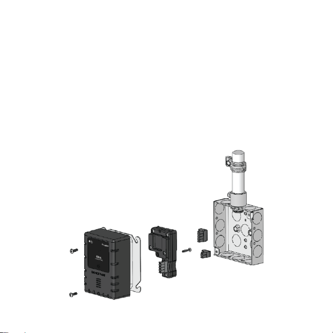
Rear exploded view 5
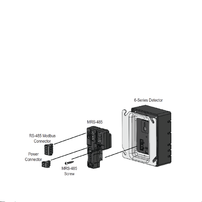
Front exploded view 6
Signal wire 7
Topology 7
Typical connection diagram 7
Length 8
Grounding 8
Power 8
DIP Switch Figure 8
Settings 9
Programming 9
MRS-485 Detail 10
4-20mA Test Points 12
Normal Operation 12
Error Codes 13
DIP Switch Setting Codes 13
General 14
Operation Test 14
Manual Operation Test 14
2
Page 3
GENERAL SAFETY INFORMATION
Intended Use
The Macurco MRS-485 adapter is an accessory used to convert the 4-20mA analog signal from Macurco 6-Series type detectors to
a digital signal for use with multipoint addressable systems. The Macurco MRS-485 simply plugs into the back of the detector and a
single screw fastens it in place. The MRS-485 accepts the 4-20mA output and is powered from the same connection as the
detector. The MRS-485 has the ability to interface with Building Automation Systems, Control Panels or other Control Devices that
accept Modbus communications.
List of Warnings and Cautions within these User Instructions
Each person using this equipment must read and understand the information in these User Instructions before use. Use of this
equipment by untrained or unqualified persons, or use that is not in accordance with these User Instructions, may adversely
affect product performance and result in sickness or death.
This equipment may not function effectively below 0°F or above 125°F (-18°C or above 52°C). Using the detector outside of
this temperature range may adversely affect product performance and result in sickness or death.
Do not disassemble unit or attempt to repair or modify any component of this instrument. This instrument contains no user
serviceable parts, and substitution of components may impair product performance and result in sickness or death.
USE INSTRUCTIONS AND LIMITATIONS
Each person using this equipment must read and understand the information in these User Instructions before use. Use of this
equipment by untrained or unqualified persons, or use that is not in accordance with these User Instructions, may adversely affect
product performance and result in sickness or death.
Use For
The Macurco MRS-485 Adapter converts the Macurco 6-Series 4-20mA analog output to a digital output for use with addressable
network systems. The Macurco 6-Series is a family of fully programmable, low voltage, dual relay gas detectors, controllers and
transducers for BAS, HVAC and Fire & Security applications. The 6-Series detectors are used to measure the concentration of
various gas and provide feedback and automatic control to help ensure a safe environment: Carbon Monoxide, Methane, Propane,
Hydrogen, Nitrogen Dioxide and other gases.
Do Not Use For
The MRS-485 is not intended for use in hazardous locations or industrial applications such as refineries, chemical plants, etc. Do
not mount the MRS-485 where the normal ambient temperature is below 0°F or exceeds 125°F (-18°C or above 52°C). The MRS485 mounts to a Macurco 6-Series detector installed on a 4” x 4” electrical box electrical box supplied by the contractor.
! WARNING
! WARNING
3
Page 4

This equipment may not function effectively below 0°F or above 125°F (-18°C or above 52°C). Using the detector outside of this
temperature range may adversely affect product performance and result in sickness or death.
General Description
The Macurco MRS-485 adapter is an accessory used to convert the 4-20mA analog signal from Macurco 6-Series type detectors to
a digital signal for use with multipoint addressable systems. The Macurco MRS-485 simply plugs into the back of the detector and a
single screw fastens it in place. The MRS-485 accepts the 4-20mA output and is powered from the same connection as the
detector. The MRS-485 has the ability to interface with Building Automation Systems, Control Panels or other Control Devices that
accept Modbus communications.
Features
The Macurco MRS-485 interfaces the detector power and 4-20mA output lines with a mounted connector
The MRS-485 monitors sensor type, gas level and trouble status communications from any of the Macurco 6-Series detectors
Communication is on a MODBUS serial line with a “Two-Wire” electrical interface in accordance with EIA/TIA-485 standard
using
RTU transmission mode
Commercial type enclosure to protect and support the electronics
Tricolor LED indicates power, test and communication status
Mounts behind the detector inside of a standard 4” x 4” electrical box
Held in place on the back of the 6-Series detector with a single screw
8 bit dip switch address selector
RS-485 termination uses 4 pin connector with jumper to select termination: The user selects no termination or one of the two
Modbus line termination options
Communications connections include signal (A and B), common and shield terminals
Intended for use in non-hazardous areas such as parking garages, warehouses or other commercial facilities
Specifications
Power & Current (with detector): 3.25W (max) from 12 to 24 VAC or VDC, 85mA in alarm, 60mA fan relay on and 33mA stand
by @ 24 VDC
Shipping Weight: 0.25 lb (0.11 kg)
Size: 3 1/2 x 2 x 1 3/4 in. (8.9 X 5.1 X 4.4 cm)
Operating Environment: 0°F to 125° F (-18°C to +52°C), 10 to 90% RH non-condensing
Connections: plugs/terminals
Color: Black
Mounting screw and screwdriver included
MRS-485 operates in the RTU Modbus Transmission Mode
Baud Rate: 4800, 9600, 19200 (default), 38400, 57600, 115200 bps
Parity: Odd, Even (default) and None
! WARNING
4
Page 5
INSTALLATION AND OPERATING INSTRUCTIONS
The following instructions are intended to serve as a guideline for the use of the Macurco Modbus RS-485 Adapter MRS-485. It is
not to be considered all-inclusive, nor is it intended to replace the policy and procedures for each facility. If you have any doubts
about the applicability of the equipment to your situation, call Technical Service at 1-877-367-7891.
Location
Refer to the user instructions of the specific Macurco 6-Series gas detector to which the MRS-485 will be connected.
Installation
Gas Detection
The Macurco MRS-485 Adapter converts the Macurco 6-Series 4-20mA analog output to a digital output for use with addressable
network systems The Macurco 6-Series is a family of fully programmable, low voltage, dual relay gas detectors, controllers and
transducers for BAS, HVAC and Fire & Security applications. The 6-Series detectors are used to measure the concentration of
various gas and provide feedback and automatic control to help ensure a safe environment: Carbon Monoxide, Methane, Propane,
Hydrogen, Nitrogen Dioxide and other gases.
1. Remove the 4-20mA/Power plug from the Macurco 6-Serires gas detector
2. Plug the MRS-485 adapter into the empty socket.
3. Install the provided MRS-485 screw.
4. See the wiring diagram for wire connection.
1. The 6-Series detector mounts on a 4”x 4” electrical box supplied by the contractor.
2. Connect the detector to the control cables with terminal plugs. When making connections, make sure the power is off.
5
!
Page 6
3. There are two terminals for the dry alarm relay contacts, again with no polarity preference. The alarm relay can switch up to 0.5
A 120 V, or 60 VA. The alarm relay is activated if gas reaches or exceeds the alarm settings. See OPERATION section of the
detector User Instructions for details on relay settings.
4. The alarm relay can be configured to normally open (default) (N.O.) or normally closed (N.C.) and will activate if the gas
concentration exceeds alarm set point. It will deactivate once the gas concentration drops below the alarm set point. Note that
the “disable” setting will cause the alarm relay not to engage at all.
5. The dry contact, SPDT fan relay has three terminals. The common (COM.), normally open (N.O.) and the normally closed (N.C.)
contact. The fan relay can switch up to 5.0 A up to 240 VAC. See detector OPERATION section of the detector User
Instructions for details on relay settings.
Connection
The Macurco MRS-485 output is connected via a four terminal screw type connector. The MRS-485 adapter is wired in the standard
2W-Modbus circuits definition with selectable built-in terminating resistors at the ends of the RS-485 bus. The power for the MRS485 adapter is connected via a two terminal screw type connector, 12 to 24 VAC or 12 to 24 VDC and no polarity.
Note: Running the Modbus cable adjacent to or in the same conduit with high voltage wires is not recommended as there may be
interference from the high voltages. Line polarization should not be required for the MRS-485 but may be required for other devices
on the RS485 line - see manufacturer’s directions.
6
Page 7
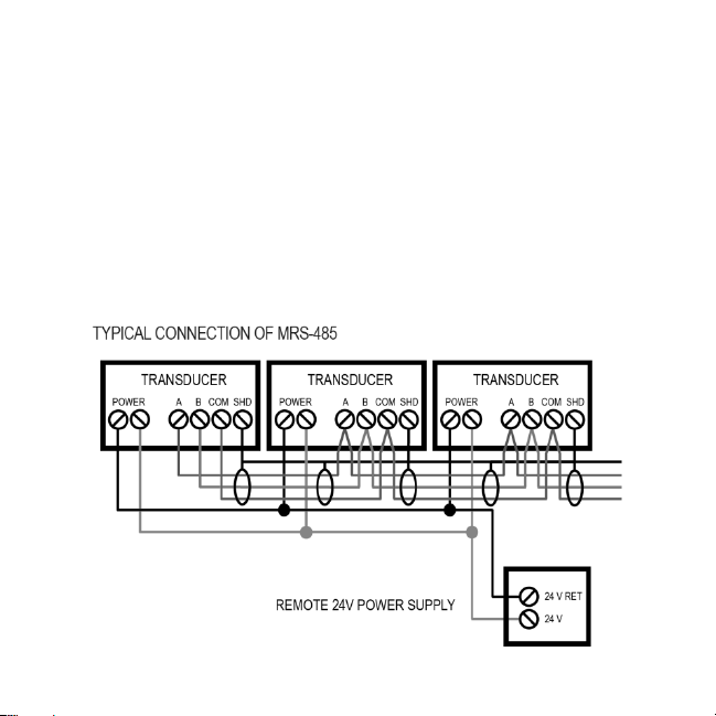
Wiring
Signal Wire
A MODBUS over Serial Line Cable should be shielded for best performance. The shield should be connected on each detector at
SHD terminal and connected to a ground terminal or chassis only at one end of the bus. An RS485-MODBUS must use a balanced
pair (for A-B) and a third wire (for the Common). For RS485-MODBUS, Wire Gauge must be chosen sufficiently wide to permit the
maximum length (1000 m or 3281ft). AWG 24 is always sufficient for the MODBUS Data. Category 5 cables may operate for RS485MODBUS, to a maximum length of 600 m 1968.5 ft. For the balanced pairs used in an RS485-system, wire with a characteristic
impedance of higher than 100 Ohms may be preferred, especially for 19200 and higher baud rates.
Note: It is recommended to always use twisted wires to reduce noise and allow for reliable data communication over greater
distances. Use at least 3-conductor wire with one twisted pair providing a pair for signal (A & B) and common (COM) connections.
For best performance use shielded 3-conductor wire with one twisted pair providing a pair for signal (A & B), common (COM) and
shield ground (SHD) connections.
Topology
An RS485-MODBUS configuration without repeater has one trunk cable, along which devices are connected, directly (daisy
chaining) or by short derivation cables. The trunk cable, also named “Bus”, can be long. Its two ends must be connected on Line
Terminations. (see Line Termination - End of Line Resistor section). The use of repeaters between several RS485-MODBUS is also
possible.
7
Page 8
Length
The end to end length of the trunk cable must be limited. The maximum length depends on the baud rate, the cable (Gauge,
Capacitance or Characteristic Impedance), the number of loads on the daisy chain, and the network configuration (2-wire). For a
maximum 9600 Baud Rate and AWG26 (or wider) gauge, the maximum length is 1000m 3281ft. The derivations must be short,
never more than 20m 65.5ft. If a multi-port tap is used with n derivations, each one must respect a maximum length of 40m 131ft
divided by n.
Grounding
The Common circuit (COM) must be connected directly to protective ground, preferably at one point only for the entire bus.
Power Wire
All field wiring is completed via modular connectors (provided). After wiring, simply plug the modular connectors into the matching
connectors on the MRS-485. The power connections to the remote mounted detectors should be size AWG18 (minimum) for short
runs. Since Macurco detectors are rated for operation between 12 and 24 VDC or VAC, the voltage drop between the power supply
and the MRS-485 should not be an issue if the recommended power wire gauge guidelines below are followed. The terminals will
accept wire from 16 to 28 AWG. To install a wire, strip back approximately 0.25 in. (6 mm) of insulation, and insert the bare wire into
the terminal. Tighten the screw clamp and ensure that the wire cannot be easily pulled from the connector.
Maximum Run Length
Wire gauge feet meters
18 500 152
16 800 244
14 1250 381
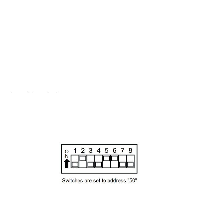
DIP Switches and Addressing
Each MRS-485 (and the partner gas detector) must be configured to a unique address. If there are 10 detectors on the serial line,
then 10 unique addresses must be used, one for each detector. To set the address use the eight DIP switch positions. For each unit
choose the value from 1 to 247 (see chart) and set the eight switches to match the address. UP means ON or 1 and DOWN means
OFF or 0. For example, to configure a unit as address “50”, set switches “2, 5, 6” (see table) to ON or in the up position (01001100).
See page 11 for a list of applicable addresses and dip-switch settings.
8
Page 9

Changing MRS-485 settings
The DIP switches are to set the Modbus address and are also used to change the MRS-485 settings. Valid Modbus addresses are
between 1 and 247 where switch 1 is the least significant bit (LSB) and switch 8 is the most significant bit (MSB). Address 254 is
used to place the MRS-485 in programming mode and the rest of addresses (248 to 253, 255, 0) are invalid MODBUS addresses.
Programming Mode
When the address is set to 254 the MRS-485 enters programming mode and the LED pattern: Alternating RED/GREEN every 200
milliseconds, indicates that the MRS-485 is ready and waiting for the user to enter new settings using the 8 switches. Using the 8
switches the user can change the communication settings like baud rate and parity as well as the registration behaviour.
When looking at the switches with the “Address” marking on top, the switches are defined from left to right as:
- Switch 8, switch 7 and switch 6 are used to modify baud rate
- Switch 5 and switch 4 are used to modify parity
- Switch 3 and switch 2 are used to modify registration mode
- Switch 1 is used to request to save the new settings
Switch 8 Switch 7 Switch 6 Description
OFF OFF OFF Default baud rate (19200 Bd)
OFF OFF ON 4800 Bd
OFF ON OFF 9600 Bd
OFF ON ON 19200 Bd (Default value)
ON OFF OFF 38400 Bd
ON OFF ON 57600 Bd
ON ON OFF 115200 Bd
ON ON ON Do not change
Switch 5 Switch 4 Description
OFF OFF Default parity (EVEN)
OFF ON Parity is ODD
ON OFF Parity is NONE
ON ON Do not change
Registration mode can be latched or unlatched. MRS-485 is always using data from a valid registration but when registration is
latched it will also compare the saved value with the new one and set a flag if it is different. This way, by reading the flag, you can
check if it is a different sensor type and you always get data about the sensor present.
Switch 3 Switch 2 Description
OFF OFF Default registration mode (Registration not latched)
OFF ON Registration not latched (Default value)
ON OFF Registration is latched
ON ON Do not change
9
Page 10
Set the switches to the desired value and then set switch 1 to ON and then OFF and the new settings will be saved in EERPOM.
The result of saving operation is displayed on LED: Alternating RED/OFF every 200 milliseconds indicates that saving new settings
failed and Alternating GREEN/OFF every 200 milliseconds indicates that saving new settings passed. Once the new settings have
passed, set the address for the device using the Address switches.
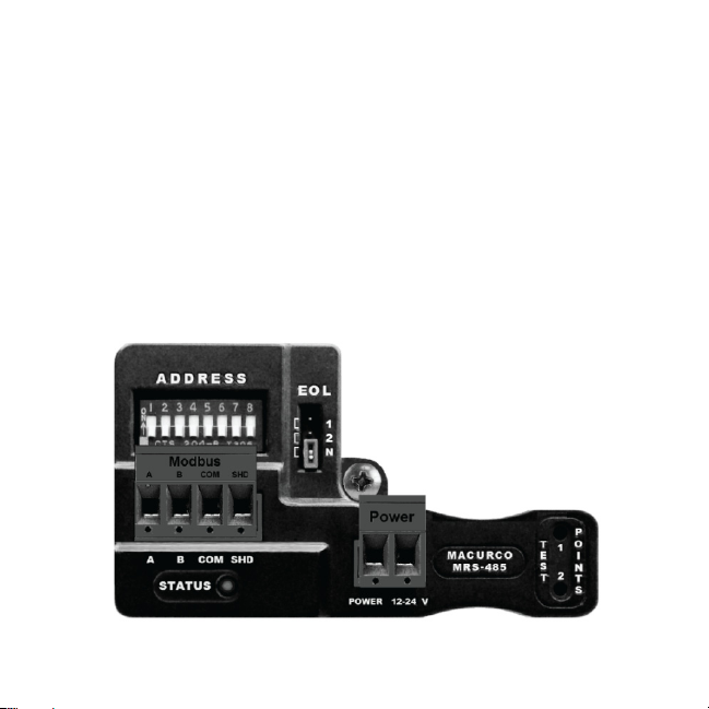
Line Termination - End of Line Resistor
The MRS-485 adapter is wired in the standard 2W-Modbus circuits definition with selectable built-in terminating resistors at the ends
of the RS-485 bus. The MRS-485 provides integral termination for end of line resistors (EOL). The MRS-485 termination uses 4 pin
connector with jumper to select termination: The user selects no termination or one of the two Modbus line termination options. The
MRS485 has two line termination options provided onboard that should cover most situations.
Place the EOL jumper on one of the following positions:
1 = 100 ohm
2 = 120 ohm
N = No termination (default)
If Line Termination requirements are different than those provided then the line termination will need to be provided by the installer.
10
Page 11

1 = 1
2 = 2
3 = 1, 2
4 = 3
5 = 1, 3
6 = 2, 3
7 = 1, 2, 3
8 = 4
9 = 1, 4
10 = 2, 4
11 = 1, 2, 4
12 = 3, 4
13 = 1, 3, 4
14 = 2, 3, 4
15 = 1, 2, 3, 4
16 = 5
17 = 1, 5
18 = 2, 5
19 = 1, 2, 5
20 = 3, 5
21 = 1, 3, 5
22 = 2, 3, 5
23 = 1, 2, 3, 5
24 = 4, 5
25 = 1, 4, 5
26 = 2, 4, 5
27 = 1, 2, 4, 5
28 = 3, 4, 5
29 = 1, 3, 4, 5
30 = 2, 3, 4, 5
31 = 1, 2, 3, 4, 5
32 = 6
33 = 1, 6
34 = 2, 6
35 = 1, 2, 6
36 = 3, 6
37 = 1, 3, 6
38 = 2, 3, 6
39 = 1, 2, 3, 6
40 = 4, 6
41 = 1, 4, 6
42 = 2, 4, 6
43 = 1, 2, 4, 6
44 = 3, 4, 6,
45 = 1, 3, 4, 6
46 = 2, 3, 4, 6
47 = 1, 2, 3, 4, 6
48 = 5, 6
49 = 1, 5, 6
50 = 2, 5, 6
51 = 1, 2, 5, 6
52 = 3, 5, 6
53 = 1, 3, 5, 6
54 = 2, 3, 5, 6
55 = 1, 2, 3, 5, 6
56 = 4, 5, 6
57 = 1, 4, 5, 6
58 = 2, 4, 5, 6
59 = 1, 2, 4, 5, 6
60 = 3, 4, 5, 6
61 = 1, 3, 4, 5, 6
62 = 2, 3, 4, 5, 6
63 = 1, 2, 3, 4, 5, 6
64 = 7
65 = 1, 7
66 = 2, 7
67 = 1, 2, 7
68 = 3, 7
69 = 1, 3, 7
70 = 2, 3, 7
71 = 1, 2, 3, 7
72 = 4, 7
73 = 1, 4, 7
74 = 2, 4, 7
75 = 1, 2, 4, 7
76 = 3, 4, 7
77 = 1, 3, 4, 7
78 = 2, 3, 4, 7
79 = 1, 3, 4, 7
80 = 5, 7
81 = 1, 5, 7
82 = 2, 5, 7
83 = 1, 2, 5, 7
84 = 3, 5, 7
85 = 1, 3, 5, 7
86 = 2, 3, 5, 7
87 = 1, 2, 3, 5, 7
88 = 4, 5, 7
89 = 1, 4, 5, 7
90 = 2, 4, 5, 7
91 = 1, 2, 4, 5, 7
92 = 3, 4, 5, 7
93 = 1, 3, 4, 5, 7
94 = 2, 3, 4, 5, 7
95 = 1, 2, 3, 4, 5, 7
96 = 6, 7
97 = 1, 6, 7
98 = 2, 6, 7
99 = 1, 2, 6, 7
100 = 3, 6, 7
101 = 1, 3, 6, 7
102 = 2, 3, 6, 7
103 = 1, 2, 3, 6, 7
104 = 4, 6, 7
105 = 1, 4, 6, 7
106 = 2, 4, 6, 7
107 = 1, 2, 4, 6, 7
108 = 3, 4, 6, 7
109 = 1, 3, 4, 6, 7
110 = 2, 3, 4, 6, 7
111 = 1, 2, 3, 4, 6, 7
112 = 5, 6, 7
113 = 1, 5, 6, 7
114 = 2, 5, 6, 7
115 = 1, 2, 5, 6, 7
116 = 3, 5, 6, 7
117 = 1, 3, 5, 6, 7
118 = 2, 3, 5, 6, 7
119 = 1, 2, 3, 5, 6, 7
120 = 4, 5, 6, 7
121 = 1, 4, 5, 6, 7
122 = 2, 4, 5, 6, 7
123 = 1, 2, 4, 5, 6, 7
124 = 3, 4, 5, 6, 7
125 = 1, 3, 4, 5, 6, 7
126 = 2, 3, 4, 5, 6, 7
127 = 1, 2, 3, 4, 5, 6, 7
128 = 8
129 = 1, 8
130 = 2, 8
131 = 1, 2, 8
132 = 3, 8
133 = 1, 3, 8
134 = 2, 3, 8
135 = 1, 2, 3, 8
136 = 4, 8
137 = 1, 4, 8
138 = 2, 4, 8
139 = 1, 2, 4, 8
140 = 3, 4, 8
141 = 1, 3, 4, 8
142 = 2, 3, 4, 8
143 = 1, 2, 3, 4, 8
144 = 5, 8
145 = 1, 5, 8
146 = 2, 5, 8
147 = 1, 2, 5, 8
148 = 3, 5, 8
149 = 1, 3, 5, 8
150 = 2, 3, 5, 8
151 = 1, 2, 3, 5, 8
152 = 4, 5, 8
153 = 1, 4, 5, 8
154 = 2, 4, 5, 8
155 = 1, 2, 4, 5, 8
156 = 3, 4, 5, 8
157 = 1, 3, 4, 5, 8
158 = 2, 3, 4, 5, 8
159 = 1, 2, 3, 4, 5, 8
160 = 6, 8
161 = 1, 6, 8
162 = 2, 6, 8
163 = 1, 2, 6, 8
164 = 3, 6, 8
165 = 1, 3, 6, 8
166 = 2, 3, 6, 8
167 = 1, 2, 3, 6, 8
168 = 4, 6, 8
169 = 1, 4, 6, 8
170 = 2, 4, 6, 8
171 = 1, 2, 4, 6, 8
172 = 3, 4, 6, 8
173 = 1, 3, 4, 6, 8
174 = 2, 3, 4, 6, 8
175 = 1,2, 3, 4, 6, 8
176 = 5, 6, 8
177 = 1, 5, 6, 8
178 = 2, 5, 6, 8
179 = 1, 2, 5, 6, 8
180 = 3, 5, 6, 8
181 = 1, 3, 5, 6, 8
182 = 2, 3, 5, 6, 8
183 = 1, 2, 3, 5, 6, 8
184 = 4, 5, 6, 8
185 = 1, 4, 5, 6, 8
186 = 2, 4, 5, 6, 8
187 = 1, 2, 4, 5, 6, 8
188 = 3, 4, 5, 6, 8
189 = 1, 3, 4, 5, 6, 8
190 = 2, 3, 4, 5, 6, 8
191 = 1, 2, 3, 4, 5, 6, 8
192 = 7, 8
193 = 1, 7, 8,
194 = 2, 7, 8,
195 = 1, 2, 7, 8
196 = 3, 7, 8
197 = 1, 3, 7, 8
198 = 2, 3, 7, 8
199 = 1, 2, 3, 7, 8
200 = 4, 7, 8,
201 = 1, 4, 7, 8
202 = 2, 4, 7, 8
203 = 1, 2, 4, 7, 8
204 = 3, 4, 7, 8
205 = 1, 3, 4, 7, 8
206 = 2, 3, 4, 7, 8
207 = 1, 2, 3, 4, 7, 8
208 = 5, 7, 8
209 = 1, 5, 7, 8
210 = 2, 5, 7, 8
211 = 1, 2, 5, 7, 8
212 = 3, 5, 7, 8
213 = 1, 3, 5, 7, 8
214 = 2, 3, 5, 7, 8
215 = 1, 2, 3, 5, 7, 8
216 = 4, 5, 7, 8
217 = 1, 4, 5, 7, 8
218 = 2, 4, 5, 7, 8
219 = 1, 2, 4, 5, 7, 8
220 = 3, 4, 5, 7, 8
221 = 1, 3, 4, 5, 7, 8
222 = 2, 3, 4, 5, 7, 8
223 = 1, 2, 3, 4, 5, 7, 8
224 = 6, 7, 8
225 = 1, 6, 7, 8
226 = 2, 6, 7, 8
227 = 1, 2, 6, 7, 8
228 = 3, 6, 7, 8
229 = 1, 3, 6, 7, 8
230 = 2, 3, 6, 7, 8
231 = 1, 2, 3, 6, 7, 8
232 = 4, 6, 7, 8
233 = 1, 4, 6, 7, 8
234 = 2, 4, 6, 7, 8
235 = 1, 2, 4, 6, 7, 8
236 = 3, 4, 6, 7, 8
237 = 1, 3, 4, 6, 7, 8
238 = 2, 3, 4, 6, 7, 8
239 = 1, 2, 3, 4, 6, 7, 8
240 = 5, 6, 7, 8
241 = 1, 5, 6, 7, 8
242 = 2, 5, 6, 7, 8
243 = 1, 2, 5, 6, 7, 8
244 = 3, 5, 6, 7, 8
245 = 1, 3, 5, 6, 7, 8
246 = 2, 3, 5, 6, 7, 8
247 = 1, 2, 3, 5, 6, 7, 8
254 = 2, 3, 4, 5, 6, 7, 8
Page 12

Power Up
The Macurco 6-Series detector cycles through an internal self-test cycle for the first minute that it is powered. The unit will execute
the test cycle any time power is dropped and reapplied (i.e. power failure). During the self-test cycle the unit will display the firmware
version number, then count down from 60 to 0 (if the display setting is “On”) and finally go into normal operation. The alarm relay will
be activated for 10 seconds and the fan relay for 60 seconds during the power-up cycle unless the “Power Up Test” (PUt) option is
OFF. The indicator light (LED) will flash green during the self-test cycle. At the end of the 1 minute cycle, the unit will take its first
sample of the air and the indicator light will turn solid green.
The MRS-485 is an adapter which allows the reading of a 6-Series gas detector over a Modbus interface. To achieve this, the MRS485 will monitor the 4-20 mA current output of the detector. At power up and during its warm-up period, the 6-Series detector will
communicate its sensor type over the 4-20 current output using a custom protocol. The MRS-485 will automatically register each 6Series detector as it is programmed with information about all the detectors to which it can be connected. The MRS-485 will use this
information to determine the gas level sensed by the 6-Series detector by measuring the 4-20 mA current-loop output during normal
operation of the detector.
4-20mA Test Points
The MRS-485 has two Test Points labeled 1 and 2. These are provided to test the 4-20mA analog output directly from the detector,
using a meter and probes, without having to remove the MRS-485 from the detector. See the Testing section for more detail.
Operation
1. With the display function turned “On”, the 6-Series detector will show the current concentration of gas or “0” (zero) in clean air.
When the gas concentration reaches the Fan Relay setting the display will flash back and forth between “FAn” and that
concentration. With the display function turned ”Off”, the display does not show the gas concentration, but will show “FAn” as
long as the fan relay is activated.
2. With the display function turned “On” and the gas concentration reaching the Alarm Relay setting, the display will flash back and
forth between “ALr” and that concentration. The buzzer will sound indicating “Alarm” if the buzzer is turned “On”. With the
display function turned off the display does not show the gas concentration, but will show “ALr” when the Alarm relay is
activated.
3. With the 4-20 mA function turned “On” and the gas concentration climbing, the 4-20 mA signal will ramp up corresponding to the
concentration. The display will show “FAn” and “ALr” and sound as outlined above. The MRS-485 will monitor the 4-20 mA
current output of the detector. The MRS-485 has a Tricolor LED (RED, GREEN and AMBER) which is used to display the
status.
Normal Operation
1. When the LED is solid GREEN, operation is normal, the MRS-485 knows the detector type, no errors are detected and no
MODBUS data are being received or transmitted over the RS-485 line.
2. When the LED is GREEN with random bursts of AMBER, operation is normal and now data are being received or transmitted
over the RS-485 line. The AMBER LED will come on anytime that there is data traffic.
Page 13

Onboard Diagnostics
Unknown Sensor Code
GREEN/OFF Alternating every 500 milliseconds - The MRS-485 doesn’t know the detector type, no MODBUS communications is in
progress and no errors are detected.
To correct this condition:
1. Disconnect the power line from the MRS-485.
2. Disconnect the MODBUS line from the MRS-485.
3. Re-connect the Modbus Line to the MRS-485.
4. Re-connect the power line to the MRS-485.
Error Codes
Solid RED - The MRS-485 detected an error and no MODBUS communications are in progress.
RED with random bursts of AMBER - The MRS-485 detected an error and AMBER is displayed when data are received or
transmitted over the RS-485 line.
There are a number of conditions which are signalized in this way:
- Current EEPROM Settings not initialized
- Current EEPROM Settings have bad checksum
- Factory EEPROM Settings not initialized
- Factory EEPROM Settings have bad checksum
- Unknown Sensor exponent value
- Watchdog reset
- Loaded Factory EEPROM Settings in EEPROM Current Settings
- Latched sensor type different than registered sensor type
- Unknown sensor type because registration failed
Dip Switch Settings Codes
RED/GREEN Alternating every 200 milliseconds indicates that MRS-485 is in programming mode and waiting for user to enter new
settings using the 8 switches.
RED/OFF alternating every 200 milliseconds indicates that saving new settings failed.
GREEN/OFF alternating every 200 milliseconds indicates that saving new settings passed.
RED/OFF alternating every 500 milliseconds indicates that selected MODBUS address is not an accepted value.
13
Page 14

6-Series Testing
General
The Macurco MRS-485 adapter converts the 4-20mA analog signal from Macurco 6-Series type detectors to a digital signal for use
with multipoint addressable systems. The 6-Series test procedures may be used to ensure that the MRS-485 accepts the 4-20mA
output for the Modbus communications. All 6-Series detectors are factory calibrated and 100% tested for proper operation. The units
also perform a regular automatic self-test during normal operation. If the unit detects an improper voltage or inoperable component,
it will default into Error mode. In this error mode, the Fan and Alarm relays will be activated, the 4-20 mA output will go to 24 mA, the
unit will display the error code and the buzzer will chirp intermittently.
Operation Test
Normally this will be the only test required for the 6-Series detectors and is the recommended way to test the unit or units after
installation. Check that the green detector operating LED light is illuminated continuously. If not, do not proceed with the tests. If the
unit is in error mode contact your local representative or Macurco technical service representative for information on resolving the
problem.
1. Remove the single screw in the middle of the front cover of the 6-Series detector.
2. Remove the front cover.
3. Observe the LED light on the front of the 6-Series detectors.
4. If the light is solid green proceed to step 6.
5. If the light is off or flashing Green, refer to the General section above.
6. Locate the switch labeled ENTER/TEST on the left side of the printed circuit board. Press the Test switch once.
7. The 6-Series detector will step through a cycle test:
a. The display progresses through the bUZ (Buzzer Test) Art (alarm relay test), Frt (fan relay test) then 42t (4-20 mA output
test).
b. Make sure that the settings are “on” or not disabled “diS”.
c. During the first 10 seconds of the test cycle, the display will show BUZ and set off the audible buzzer
d. The alarm relay will be closed, so any devices connected to that relay will be tested.
e. The Fan relay will be activated for the next 1 minute of the test, so if the fan circuits are wired in the normal manner, the fan
should run.
f. The 4-20mA output will then ramp up from 4 to 16 mA over the next 130 seconds of the test, so if the circuit is wired in the
normal manner, the control panel or building automation system should respond.
g. At the end of the test cycle, the light will turn green and be on steady (Normal Operation), the fan & alarm relay will be in
standby mode and the 4-20 mA output will return to 4 mA (in clean air).
8. When testing is completed reassemble the unit or units.
14
Page 15

Manual Operation Test
This option gives the user the opportunity to manually initiate an individual test for each relay, the analog output and the sensor
response to gas. From normal operation mode press the Next button 3 times to get to the Test Mode (tSt). Press the Enter button
once to get into the Test Menu. Press the Next button to scroll through the four test options and press Enter to initiate the selected
test. Note that if the relay or 4–20 mA output has been disabled, the test selection will not be displayed in the test menu.
Art - Alarm Relay Test, 10 seconds
Frt - Fan Relay Test, 60 seconds
42t - 420 loop test, 25 seconds
MAINTENANCE
The MRS-485 does not require regular maintenance. All maintenance and repair of products manufactured by Macurco are to be
performed at the appropriate Macurco manufacturing facility. Macurco does not sanction any third-party repair facilities.
! WARNING
Do not disassemble unit or attempt to repair or modify any component of this instrument. This instrument contains no user
serviceable parts, and substitution of components may impair product performance and result in sickness or death.
CAUTION
Avoid the use of harsh cleaning materials, abrasives and other organic solvents. Such materials may permanently scratch the
surfaces and damage the LEDs labels or instrument housing.
Cleaning
Cleaning of the external surfaces is best carried out using a damp cloth with a mild detergent or soap. Use a vacuum cleaner with
soft brush to remove dust or contamination. Do not blow out the sensor with compressed air.
15
Page 16

MACURCO FIXED GAS DETECTION PRODUCTS LIMITED WARRANTY
Macurco warrants the MRS-485 adapter will be free from defective materials and workmanship for a period of two (2) years from
date of manufacture (indicated on the cover of the MRS-485), provided it is maintained and used in accordance with Macurco
instructions and/or recommendations. If any component becomes defective during the warranty period, it will be replaced or repaired
free of charge, if the unit is returned in accordance with the instructions below. This warranty does not apply to units that have been
altered or had repair attempted, or that have been subjected to abuse, accidental or otherwise. The above warranty is in lieu of all
other express warranties, obligations or liabilities. THE IMPLIED WARRANTIES OF MERCHANTABILITY AND FITNESS FOR
PARTICULAR PURPOSE ARE LIMITED TO A PERIOD OF TWO (2) YEARS FROM THE PURCHASE DATE. Macurco shall not be
liable for any incidental or consequential damages for breach of this or any other warranty, express or implied, arising out of or
related to the use of said gas detector. Manufacturer or its agent’s liability shall be limited to replacement or repair as set forth
above. Buyer’s sole and exclusive remedies are return of the goods and repayment of the price, or repair and replacement of nonconforming goods or parts.
Manufactured by Aerionics, Inc.
Sioux Falls, SD
Email: info@aerionicsinc.com
Phone: 1-877-367-7891
Rev 06.29.2015
© Aerionics 2015. All rights reserved.
Macurco is a trademark of Aerionics, Inc.
16
Page 17

Macurco
™ Modbus® RS-485 Adaptador MRS-485
Instrucciones para el usuario
IMPORTANTE: Mantenga estas Instrucciones como referencia
Page 18

TABLA DE CONTENIDO
INFORMACIÓN GENERAL DE SEGURIDAD 3
INSTRUCCIONES DE USO Y LIMITACIONES 3
INSTRUCCIONES DE INSTALACIÓN Y OPERACIÓN 5
MANTENIMIENTO 15
GARANTÍA DE LOS PRODUCTOS MARUCO DE DETECCIÓN DE GAS 16
Uso previsto 3
Lista de Advertencias y Precauciones 3
Utilice Para 3
No utilice para 3
Descripción General 4
Características 4
Especificaciones 4
Ubicación 5
Inst alación 5
Conexión 6
Cableado 7
Interruptores DIP y direccionamiento 8
Teminación de línea 10
Tabla de configuración del interruptor Dip 11
Carga 12
Operación 12
Diagnósticos a bordo 13
Pruebas 14
Limpieza 15
Vista trasera desarrollada 5
Vista f rontal desarrollada 6
Cable de señal 7
Topología 7
Diagrama de conexión típica 7
Longitud 8
Toma de tierra 8
Energía 8
Figura del interruptor DIP 8
Ajustes 9
Programación 9
Detalle de MRS-485 10
Puntos de prueba 4-20 mA 12
Operación Normal 12
Códigos de error 13
Códigos de configuración del interruptor DIP 13
General 14
Prueba de funcionamiento 14
Prueba manual de funcionamiento 15
2
Page 19

INFORMACIÓN GENERAL DE SEGURIDAD
Uso previsto
El adaptador Macurco MRS-485 es un accesorio utilizado para convertir la señal analógica 4-20 mA de los detectores Macurco 6Series a una señal digital para su uso con los sistemas direccionables multipunto. El Macurco MRS-485 sólo se conecta a la parte
posterior del detector y es sostenido en su lugar por un so lo tornillo. El MRS-485 acepta la salida 4-20 mA y, al igual que el
detector, se alimenta de la misma conexión. El MRS-485 tiene la capacidad de interactuar con los sistemas de automatización de
edificios, con los paneles de control o con otros dispositivos de control que acepten las comunicaciones Modbus.
Lista de advertencias y precauciones en estas instrucciones para el usuario
Antes de usar este equipo, cada persona, que lo utilice, debe leer y entender la información en estas instrucciones El uso de
este equipo por personas no capacitadas o no calificadas, o el uso sin seguir las instrucciones para el usuario, puede afectar
negativamente el rendimiento del producto, e incluso ocasionar enfermedad o muerte.
Este equipo no funciona adecuadamente en una temperatura por debajo de los 0 ° F o por encima de lo s 125 ° F (-18 ° C o
por encima de los 52 ° C). Usar el detector fuera de este rango de temperatura puede afectar negativamente el desempeño del
producto, e incluso ocasionar enfermedad o muerte.
No desarme la unidad ni intente reparar o modificar ninguno de los componentes de este instrumento. Este instrumento
no contiene ninguna pieza que el usuario pueda reparar y l a sustitución de componentes puede afectar el rendimiento
del producto, e incluso ocasionar enfermedad o muerte.
INSTRUCCIONES DE USO Y LIMITACIONES
Antes de usar este equipo, cada persona que lo utilice, debe leer y entender la información en estas Instrucciones. El uso de
este equipo por personas no capacitadas o no calificadas, o el uso sin seguir las instrucciones para el usuario, puede afectar
negativamente el rendimiento del producto, e incluso ocasionar enfermedad o muerte.
Utilice Para
El adaptador Mar u co MRS-485 convierte la salida analógica del Macurco 6-Series de 4-20 mA a una salida digital para los
sistemas de red direccionables. El Macurco 6-Series es una familia de detectores de gas du ales, de controlad ore s y d e
transductores totalmente programables y de baja tensión para los sist emas de aut omati zació n d e edif icios (BAS, por sus
siglas en inglés), para la calefacción, la ventilación y el aire acondicionado (HVAC, por sus siglas en inglés) y p ara i ncend ios y
se gur id a d. Los detectores 6-Series se utilizan para medir la concentración de varios gases: monóxido de carbono, metano,
propano, hidrógeno, dióxido de nitrógeno y otros gases; y para proporcionar una retroalimentación y un control automático que
ayude a garantizar un ambiente seguro
No utilice para
El MRS-485 no está diseñado para su uso en lugares peligrosos o para aplicaciones industriales tales como en refinerías, plantas
químicas, etc. No instale el MRS-485 donde la temperatura ambiente normal sea inferior a los 0 ° F o superior a los 125 ° F (-18 ° C
o superior a los 52 ° C). El MRS-485 se instala en un detector Macurco 6-Series instalado en una caja eléctrica de 4” x 4"
suministrada por el contratista.
! ADVERTENCIA
! ADVERTENCIA
4
Page 20

Este equipo puede no funcionar adecuadamente en una temperatura por debajo de los 0 ° F o por encima de los 125 ° F (-18 ° C o
superior a los 52 ° C). Usar el detector fuera de este rango de temperatura puede afectar negativamente el desempeño del
producto, e incluso ocasionar enfermedad o muerte.
Descripción General
El adaptador Macurco MRS-485 es un accesorio utilizado para convertir la señal analógica 4-20 mA de los detectores Maruco 6-
Series a una señal digital para su uso con los sistemas direccionables multipunto. El Macurco MRS-485 sólo se conecta a la parte
posterior del detector y se sostiene en su lugar por un solo tornillo. El MRS-485 acepta la salida 4-20 mA y, al igual
que el detector, se alimenta de la misma conexión. El MRS-485 tiene la capacidad de interactuar con los s i s t e m a s
de a u t o m a t i z a ci ó n d e e d if i c i o s, con los paneles de control o con otros dispositivos de control que acepten las
comunicaciones Modbus.
Características
El Macurco MRS-485 enlaza la energía del detector y las líneas de salida 4-20mA con un conector ya instalado.
Los monitores MRS-485 de tipo sensor para sondear los niveles de gas, los estátus de los problemas de cualquiera de los
detectores Maruco 6-Series.
La comunicación está sobre una línea serie MODBUS con una interfaz eléctrica "de dos cables" de acuerdo a los
estándares EIA / TIA-485 utilizados.
Modo de transmisión RTU
De tipo comercial recubierto, para proteger y ayudar a los electrónicos
El LEDTricolor indica el estado de energía, de p rueba y de comunicación
Se instala detrás del detector en el in terior de una caja eléctrica estándar 4"x 4"
Mantenga el dete ctor 6-Series con un solo tornillo en la parte posterior
Selecto r del interruptor DIP de 8 bits del direccionador
La terminación RS-485 utiliza un conector de 4 pines con un puente para seleccionarla: El usuario no selecciona ninguna
terminación o selecciona una de las dos
Opciones de terminación de la línea Modbus
Las conexiones de comunicación incluyen terminales de señal (A y B), comunes y de escudo
Diseñado para su uso en zonas no peligrosas tales como estacionamientos, almacenes u otros establecimientos comerciales
Especificaciones
Energía y corriente (con un detector): 3.25W (máximo) de 12 a 24 VAC o VDC, 85mA en estado de alarma, 60mA en el
relevador del ventilador y 33mA en el soporte de @ 24 VDC
Peso envío: 0,25 libras (0,11 kg)
Tamaño: 3 1/2 x 2 x 1 3/4 pulgadas (8,9 X 5,1 X 4,4 cm)
Medio operativo: De 0 ° F a 125 ° F (-18 ° C a + 52 ° C), de 10 a 90% de humedad relativa sin condensación
Conexiones: enchufes / terminales
Color: Negro
Tornillo de instalación y desarmador incluidos
El MRS-485 opera en el modo de transmisión Mosbus RTU
Velocidad de tran sferencia: 4800, 9600, 19200 (predeterminado), 38.400, 57.600, 115.200 bps
Paridad: Impar, Par (predeterminado) y Ninguno
! ADVERTENCIA
5
Page 21

INSTRUCCIONES DE INSTALACIÓN Y OPERACIÓN
Las siguientes instrucciones están destinadas a servir como guía para el uso del adaptador Macurco Modbus RS-485; no debe
considerarse en toda circunstancia, ni pretende reemplazar la política y los procedimientos de cada infraestructura. Si usted tiene
alguna duda acerca de la aplicación del equipo de acuerdo a su situación, llame al Servicio Técnico al 1-877-367-7891.
Ubicación
Consulte las instrucciones de uso del detector de gas Macurco 6-Series al que debe conectarse el MRS-485.
Instalación
Detección de gases
El adaptador Mac urc o MRS-485 convierte la salida analógica de l Macurco 6-Series 4-20 mA a una salida digital para el uso
de sistemas de red direccionables. El Macurco 6-Series es una familia de detectores de gas duales, de contoladores y de
transductores totalmente programables y de baja tensión para lo s sist emas d e auto matiz ación de edificio s (BAS, por sus
siglas en inglés), para la calefacción, la ventilación y el aire acondicionado (HVAC, por sus siglas en inglés) y p ara i ncend ios y
se gur ida d. Los detectores 6-Series se utilizan para medir la concentración de varios gases: monóxido de carbono, metano,
propano, hidrógeno, dióxido de nitrógeno y otros gases; y para proporcionar una retroalimentación y un control automático que
ayude a garantizar un ambiente seguro.
1. Retire la clavija 4-20 mA/de alimentación del detector de gas Macurco 6-serires
2. Conecte el adaptador MRS-485 a la toma vacía.
3. Instale el tornillo M RS-485 suministrado.
4. Vea el diagrama de cableado para la conexión de cables.
1. El detector 6-Series se instala en una caja eléctrica de “4 x “4 suministrada por el contratista.
2. Conecte el detector a los cables de control con con ectores terminales. Al hacer las conexiones, asegúrese de que la
corriente eléctrica esté desconectada.
6
Page 22

3. Hay dos terminales para los contactos secos del relevador de alarma, también sin preferencia polaridad. El relevador de
alarma se puede cambiar a 0.5 A 120 V, o a 60 VA. El relevador de la alarma se activa si el gas alcanza o excede los ajustes
de la alarma. Vea la sección de OPERACIÓN del de t e c tor e n l a s Instrucciones para el usuario para obtener más
información sobre los ajustes del relevador.
4. El relevador de la alarma se puede configurar para abr i r normalmente (predeterminado) (NO, por sus siglas en inglés) o
cerrar normalmente (NC, por sus siglas en inglés) y se activará si la concentración de gas excede el punto de ajuste de la
alarma. Se desactivará una vez que la concentración de gas caiga por debajo del punto de ajuste de la alarma. Tenga en
cuenta que el ajuste "desactivar" hará que el relevador de la alarma no
5. El contacto seco del relevador del ventilador con ti ro de p oste úni co (SPDT, por sus siglas en inglés) tiene tres terminales,
la común (COM., por sus siglas en inglés), la normalmente abierta (NO, por sus siglas en inglés) y
(NC, por sus siglas en inglés). El relevador del ventilador puede cambiar de 5,0 A a hasta 240 VAC. Vea la sección de
OPERACIÓN del detector en las Instrucciones para el usuario para obtener detalles sobre los ajustes del relevador.
Conexión
La salida del Macurco MRS-485 está conectada a través de un conector de tornillo de cuatro terminales. El adaptador MRS-485
está cableado en los circuitos de definición estándar 2W-Modbus, tiene resistencias de terminación fabricadas en los extremos del
bus RS-485.; la energía para el adaptador MRS-485 se obtiene conectándolo a un conector de tornillo con dos terminales, de 12 a
24 VAC o de 12 a 24 VDC y sin pola ridad.
Nota: hacer funcionar el cable adyacente Modbus o el mismo conducto con cables de alto voltaje no es recomendable ya que puede
haber interferencia de alto voltaje. La línea de polarización no es necesaria para el MRS-485, pero puede serlo para los otros
dispositivos de la línea RS485 - ver las instrucciones del fabricante.
se engrane
en absoluto.
la normalmente cerrada
7
Page 23

Cableado
Señal Cable
Un MODBUS sobre el cable de línea seríal debe ser blindado para un mejor rendimiento. El blindaje debe ser conectado en cada
detector en Terminal SHD y a una terminal de tierra o chasis, ésto solamente en un extremo del bus. Un RS485-MODBUS debe
utilizar un par de cables equilibrados (por A-B) y un tercer cable (para el común). El calibre del cable para el RS485-MODBUS que
debe elegirse tiene que ser lo suficientemente amplio para permitir la longitud máxima (1.000 m o 3281 pies). Generalmente, el
AWG 24 es suficiente para los datos MODBUS. Los cables de categoría 5 deben operar a su máxima longitud de 600m 1968.5 pies
para el RS485-MODBUS; para los pares equilibrados utilizados en un sistema RS485, es preferible un cable con una característica
de impedancia de más de 100 Ohms especialmente para las de 19.200 y para las de tasas de baudios más altas.
Nota: Se recomienda utilizar siempre cables trenzados para reducir el ruido y permitir la comunicación confiable de datos a largas
distancias. Utilice, al menos, un cable con 3 conductores, un par trenzado para proporcionar un par de conexiones de señal (A y B) y
una conexión común (COM).
Para un mejor rendimiento, utilice cable blindado de 3 condu ctores con un par trenzado para proporcionar un par de conexiónes de
señal (A y B), una conexión común (COM) y una conexión de tierra blindada (SHD, por sus siglas en inglés).
Topología
Una configuración RS485-MODBUS sin repetidor tiene un cable principal al cual se conectan directamente los dispositivos (conexión
margarita) o tiene cables cortos de derivación para ello. El cable principal, también llamado “Bus”, puede ser largo;.su s dos extremos
deben estar conectados a la línea de terminaciones. (Ver línea de terminaciones - Fin de la sección Línea de Resistencia). El uso de
repetidores entre varios RS485-MODBUS también es posible.
8
Page 24

Longitud
La longitud final del cable principal debe ser limitada. La longitud máxima depende de la velocidad de transmisión, del cable
(calibre, capacidad o impedancia característica), del número de cargas en la cadena margarita y de la configuración de la red (2
cables). Para una velocidad de transmisión máxima de9600 y para un calibre AWG26 (o más amplio) la longitud máxima es 1000m
3281pies. Las derivaciones deben ser cortas, nunca de más de 20m 65.5 pies; Si una conexión multipuerto se usa con n
derivaciones, cada una debe respetar una longitud máxima de 40m 131pies dividida entre n.
Toma de tierra
El circuito común (COM) debe estar conectado directamente a la tierra de protección, preferiblemente en un solo punto para todo el
bus.
Cable de alimentación
Todo el cableado en el campo se completa a través de conectores modulares (proporcionado). Después del cableado,
simplemente conecte los conectores correspondientes en el MRS-485. Los cables de alimentación de los detectores instalados a
distancia deben tener un tamaño de AWG18 (mínimo) para ejecuciones cortas. Ya que los detectores Macurco están clasificados
para la operación de 12 a 24 VDC o VAC, la caída de voltaje entre la fuente de alimentación y el MRS-485 no debería ser un
problema si se siguen las recomendaciones, que se hacen abajo, sobre de calibre del cable de alimentación . Los terminales
aceptarán un cable desde 16 hasta 24 AWG; para instalar un cable, pele aproximadamente 0,25 pulgadas. (6 mm) del aislante e
inserte el cable pelado en la terminal; apriete la abrazadera con el tornillo y asegúrese de que el cable no pueda sacarse
fácilmente del conector.
Máxima Longitud de ejecución
Sección del cable pies metros
18 500 152
16 800 244
14 1250 381
Interruptores DIP y direccionamiento
Cada MRS-485 (y el detector de gas asociado) debe configurarse a una dirección única. Si hay 10 detectores en la línea serie,
entonces se deben ut ilizar 10 direcciones únicas, una para cada de tector. Para configurar la dirección use la s ocho posiciones de
los interruptores DIP. Para cada unidad elija el valor de 1 a 247 (ver gráfico) y establezca los ocho interruptores para que coincidan
con la dirección. ARRIBA significa ON (encendido ) o 1 y ABAJO significa OFF (apagado) o 0. Por ejemplo, para configurar una
unidad como la dirección "50", ajuste los interruptores "2, 5, 6" (vea la tabla) en ON o en la posición superior (01001100). Consulte la
página 11 para ver la lista de direcciones y los ajustes aplicables a los interruptores DIP..
Los interruptores se configuran para la dirección "50"
9
Page 25

Cambiar la configuración del MRS-485
Los interruptores DIP son para configurar la dirección Modbus, aunque también se utilizan para cambiar la configuración del MRS-
485.
Las
direcciones Modbus válidas son entre 1 y 247, donde el interruptor 1 es el bit menos significativo (LSB, por sus siglas en
inglés) y el interruptor 8 es el bit más significativo (MSB, por su s siglas en inglés). L a dirección 254 es utilizada para colocar el
MRS-485 en modo de programación y el resto de las direcciones (248 a 253, 255, 0) son direcciones Modbus no válidas.
Modo de Programación
Cuando la dirección se establece en 254 el MRS-485 entra en modo de programación y el patrón de LED: ROJO / VERDE
alternando cada 200 milisegundos, eso indica que el MRS-485 está listo y en espera de que el usuario introdu zca los nuevos
ajustes usando los 8 interruptores. Utilizando lo s 8 interruptores, el usuario puede cambiar los ajustes de comunicación, por
ejemplo la velocidad de transmisión y la paridad, así como el comportamiento del registro.
Al observar los interruptores con la "Dirección" marcada en la parte superior, los interruptores se definen de izquierda a derecha como:
- Los interruptores 8, 7 y 6 se utilizan para modificar la velocidad de transmisión
- Los interruptores 5 y 4 se utilizan para modificar la paridad
- Los interruptores 3 y 2 se utilizan para modificar el modo de registro
- El interruptor 1 se utiliza para solicitar el guardar la nueva configura ción
Interruptor 8 Interruptor 7 Interruptor 6 Descripción
OFF OFF OFF Velocidad de transmisión predeterminada (19.200 Bd)
OFF OFF ON 4800 Bd
OFF ON OFF 9600 Bd
OFF ON ON 19200 Bd (valor predeterminado)
ON OFF OFF 38400 Bd
ON OFF ON 57600 Bd
ON ON OFF 115.200 Bd
ON ON ON No cambia
Interruptor 5 Interruptor 4 Descripción
OFF OFF Paridad predeterminada (UNIFORME)
OFF ON Paridad IMPAR
ON OFF Paridad NULA
ON ON No cambia
El modo de registro puede ser bloqueado o desbloqueado. E l MRS-485 siempre utiliza datos de un registro válido, pero cuando
el registro está b loqueado también comparará el valor guardado con e l nuevo y establecerá un indicador si es que éste es
diferente. De esta manera, mediante la lectura del indicador usted puede comprobar si se trata de un tipo de sensor diferente y
siempre obtendrá datos sobre el sensor actual.
Interruptor 3 Interruptor 2 Descripción
OFF OFF Modo de registro predeterminado (Registro no bloqueado)
OFF ON Registro no bloqueado (valor predeterminado)
ON OFF Registro bloqueado
ON ON No cambia
10
Page 26

Ajuste los interruptores al valor deseado, luego ajuste el interruptor 1 en ON y después en OFF, y los nuevos ajustes se guardarán
en EERPOM.
El resul tado de guardar la operación se muestra en el LED: ROJ O / OFF alternando ca da 200 milisegundos indica que
guardar la configuración nueva fracasó, mientras que VERDE / OFF alternando cada 200 milisegundos indica que la acción de
guardar la configuración nueva tuvó éxito; una vez que la configuración nueva esté guardada, establezca la dirección que debe
usar el dispositivo por medio de los interruptores de dirección.
Ter minaci ón de la línea – Extremo de la resistencia de la línea
El ada ptador MRS -485 está cableado de acuer do a la de finición de circui tos estándar 2W-Mo dbus con r esistenc ias de terminación
seleccionables incorporadas e n los ex tremos del bu s RS-48 5. El M RS-485 proporciona la terminación integral del final de las
resistencias de la línea (EOL, por sus siglas en inglés). La terminación MRS-485 utiliza 4 pines de conector con un puente para
seleccionar la terminación: El usuario no selecciona ninguna
linea Modbus.
Coloque el puente EOL en una de las siguientes posiciones:
1 = 100 ohm
2 = 120 ohm
N = Sin terminación (predeterminado)
Si los requisito s de terminación de la línea son difere ntes a los dados a continuació n, entonces la terminación de la línea tendrá
que ser provista por el instalador.
El MRS485 tiene dos opciones de terminación de la linea provistas que deben cubrir la mayoría de las situaciones.
teminación o seleccióna una de los dos opciones de terminación de la
la acción de
11
Page 27

= 1, 2, 3, 6,
= 2, 4, 5, 8
= 3, 4, 7, 8
= 2, 4, 6,
= 1, 3, 4, 5, 8
= 1, 2, 3,
= 1, 3, 4, 6,
= 6, 8
= 2, 5, 7, 8
= 5, 6, 7
= 2, 6, 8
= 3, 5, 7, 8
= 2, 5, 6,
= 1, 3, 6, 8
= 1, 2, 3,
= 1, 3, 5, 6,
= 4, 6, 8
= 2, 4, 5, 7, 8
= 2, 4, 6, 8
= 3, 4, 5, 7, 8
= 2, 4, 5, 6,
= 1, 3, 4, 6, 8
= 1, 2,
= 1, 3, 4,
= 5, 6, 8
= 2, 6, 7, 8
= 2, 5, 6, 8
= 3, 6, 7, 8
= 2,
= 1, 3, 5, 6, 8
= 1, 2, 3,
= 1, 3,
= 4, 5, 6, 8
= 2, 4, 6, 7, 8
= 2, 4, 5, 6, 8
= 3, 4, 6, 7, 8
= 2, 4,
= 1, 3, 4,
= 1, 2,
= 1, 2,
= 1, 5, 6, 7, 8
= 1, 2, 3, 4,
= 5, 8
= 2, 7, 8,
= 3, 5, 6, 7, 8
= 2, 5,
= 1, 3, 7, 8
= 1, 2,
= 1, 2, 3, 7, 8
1 = 1
2 = 2
3 = 1, 2
53 = 1, 3, 5, 6 103
4 = 3
5 = 1, 3
56 = 4, 5, 6 106
6 = 2, 3
7 = 1, 2, 3
8 = 4
59 = 1, 2, 4, 5, 6 109
9 = 1, 4
10 = 2, 4
11 = 1, 2, 4
12 = 3, 4
13 = 1, 3, 4
64 = 7 114
14 = 2, 3, 4
15 = 1, 2, 3, 4
16 = 5
67 = 1, 2, 7 117
17 = 1, 5
18 = 2, 5
19 = 1, 2, 5
20 = 3, 5
21 = 1, 3, 5
72 = 4, 7 122
22 = 2, 3, 5
23 = 1, 2, 3, 5
24 = 4, 5
25 = 1, 4, 5
75 = 1, 2, 4, 7 125
26 = 2, 4, 5
27 = 1, 2, 4, 5
28 = 3, 4, 5
29 = 1, 3, 4, 5
80 = 5, 7 130
30 = 2, 3, 4, 5
31 = 1, 2, 3, 4, 5
32 = 6
83 = 1, 2, 5, 7 133
33 = 1, 6
34 = 2, 6
35 = 1, 2, 6
36 = 3, 6
37 = 1, 3, 6
38 = 2, 3, 6
88 = 4, 5, 7 138
39 = 1, 2, 3, 6
40 = 4, 6
41 = 1, 4, 6
42 = 2, 4, 6
93 = 1, 3, 4, 5, 7 143
43 = 1, 2, 4, 6
44 = 3, 4, 6,
45 = 1, 3, 4, 6
96 = 6, 7 146
46 = 2, 3, 4, 6
47 = 1, 2, 3, 4, 6
48 = 5, 6
49 = 1, 5, 6
50 = 2, 5, 6
51 = 1, 2, 5, 6
52 = 3, 5, 6
54 = 2, 3, 5, 6
55 = 1, 2, 3, 5, 6
57 = 1, 4, 5, 6
58 = 2, 4, 5, 6
60 = 3, 4, 5, 6
61 = 1, 3, 4, 5, 6
62 = 2, 3, 4, 5, 6
63 = 1, 2, 3, 4, 5, 6
65 = 1, 7
66 = 2, 7
68 = 3, 7
69 = 1, 3, 7
70 = 2, 3, 7
71 = 1, 2, 3, 7
73 = 1, 4, 7
74 = 2, 4, 7
76 = 3, 4, 7
77 = 1, 3, 4, 7
78 = 2, 3, 4, 7
79 = 1, 3, 4, 7
81 = 1, 5, 7
82 = 2, 5, 7
84 = 3, 5, 7
85 = 1, 3, 5, 7
86 = 2, 3, 5, 7
87 = 1, 2, 3, 5, 7
89 = 1, 4, 5, 7
90 = 2, 4, 5, 7
91 = 1, 2, 4, 5, 7
92 = 3, 4, 5, 7
94 = 2, 3, 4, 5, 7
95 = 1, 2, 3, 4, 5, 7
97 = 1, 6, 7
98 = 2, 6, 7
99 = 1, 2, 6, 7
100 = 3, 6, 7
101 = 1, 3, 6, 7
102 = 2, 3, 6, 7
104 = 4, 6, 7
105 = 1, 4, 6, 7
7 156 = 3, 4, 5, 8 206 = 2, 3, 4, 7, 8
107 = 1, 2, 4, 6, 7
108 = 3, 4, 6, 7
110 = 2, 3, 4, 6, 7
111 = 1, 2, 3, 4, 6, 7
112
113 = 1, 5, 6, 7
7 164 = 3, 6, 8 214 = 2, 3, 5, 7, 8
115 = 1, 2, 5, 6, 7
116 = 3, 5, 6, 7
118 = 2, 3, 5, 6, 7
119 = 1, 2, 3, 5, 6, 7
120 = 4, 5, 6, 7
121 = 1, 4, 5, 6, 7
123 = 1, 2, 4, 5, 6, 7
124 = 3, 4, 5, 6, 7
5, 6, 7 175 = 1,2, 3, 4, 6, 8 225 = 1, 6, 7, 8
126 = 2, 3, 4, 5, 6, 7
127 = 1, 2, 3, 4, 5, 6, 7
128 = 8
129 = 1, 8
8 180 = 3, 5, 6, 8 230 = 2, 3, 6, 7, 8
131 = 1, 2, 8
132 = 3, 8
8 183 = 1, 2, 3, 5, 6, 8 233 = 1, 4, 6, 7, 8
134 = 2, 3, 8
135 = 1, 2, 3, 8
136 = 4, 8
137 = 1, 4, 8
8 188 = 3, 4, 5, 6, 8 238 = 2, 3, 4, 6, 7, 8
139 = 1, 2, 4, 8
140 = 3, 4, 8
141 = 1, 3, 4, 8
142 = 2, 3, 4, 8
144
145 = 1, 5, 8
8 196 = 3, 7, 8 246 = 2, 3, 5, 6, 7, 8
147 = 1, 2, 5, 8
148 = 3, 5, 8
149 = 1, 3, 5, 8
150 = 2, 3, 5, 8
151 = 1, 2, 3, 5, 8
152 = 4, 5, 8
7 153 = 1, 4, 5, 8 203 = 1, 2, 4, 7, 8
154
155 = 1, 2, 4, 5, 8
157
158 = 2, 3, 4, 5, 8
7 159 = 1, 2, 3, 4, 5, 8 209 = 1, 5, 7, 8
160
161 = 1, 6, 8
162
163 = 1, 2, 6, 8
165
166 = 2, 3, 6, 8
7 167 = 1, 2, 3, 6, 8 217 = 1, 4, 5, 7, 8
168
169 = 1, 4, 6, 8
170
171 = 1, 2, 4, 6, 8
7 172 = 3, 4, 6, 8 222 = 2, 3, 4, 5, 7, 8
173
174 = 2, 3, 4, 6, 8
176
177 = 1, 5, 6, 8
178
179 = 1, 2, 5, 6, 8
181
182 = 2, 3, 5, 6, 8
184
185 = 1, 4, 5, 6, 8
186
187 = 1, 2, 4, 5, 6, 8
5, 6, 8
189
190 = 2, 3, 4, 5, 6, 8
3, 4, 5, 6, 8
191
192 = 7, 8
8 193 = 1, 7, 8, 243 = 1, 2, 5, 6, 7, 8
194
195 = 1, 2, 7, 8
197
198 = 2, 3, 7, 8
199
200 = 4, 7, 8,
201 = 1, 4, 7, 8
202 = 2, 4, 7, 8
204
205 = 1, 3, 4, 7, 8
207
208 = 5, 7, 8
210
211 = 1, 2, 5, 7, 8
212
213 = 1, 3, 5, 7, 8
215
216 = 4, 5, 7, 8
218
219 = 1, 2, 4, 5, 7, 8
220
221 = 1, 3, 4, 5, 7, 8
223
224 = 6, 7, 8
226
227 = 1, 2, 6, 7, 8
228
229 = 1, 3, 6, 7, 8
231
232 = 4, 6, 7, 8
234
235 = 1, 2, 4, 6, 7, 8
236
237 = 1, 3, 4, 6, 7, 8
239
240 = 5, 6, 7, 8
241
242 = 2, 5, 6, 7, 8
244
245 = 1, 3, 5, 6, 7, 8
247
254 = 2, 3, 4, 5, 6, 7, 8
4, 7, 8
5, 7, 8
3, 4, 5, 7, 8
6, 7, 8
3, 4, 6, 7, 8
3, 5, 6, 7, 8
Page 28

Carga
Los ciclos del detector Macurco 6-Series a través de un ciclo de auto-prueba interna durante el primer minuto que está encendido.
La unidad ejecutará el ciclo de prueba al momento en el que la energía baje y suba de nuevo (es decir, falla en la energía eléctrica).
Durante el ciclo de auto-prueba la unidad mostrará el número de versión del firmware, entonces comenzará la cuenta regresiva del
60 al 0 (si los ajustes de la pantalla están “encendidos”) y, finalmente, entrará en operac ión normal. El relevador de la alarma se
activará durante 10 segundos y el relevador del ventilador durante 60 segundos durante el ciclo de encendido a menos que la
opción "Prueba de encendido" (Put) esté en OFF. La luz del indicador (LED) parpadeará en color verde durante el ciclo de autoprueba. Al final del ciclo de 1 minuto, la unidad tendrá su primera muestra de aire y la luz indicadora se encenderá en color verde.
El MRS-485 es un adaptador que permite la lectura de un detector de gas 6-Series través de una interface Modbus. Para lograr
esto, el MRS-485 supervisará la salida de corriente 4-20 mA del detector. En el encendido y durante su período de calentamiento,
el detector 6-Serie s se comunicará con su tipo de sensor en una salida de corrie nte 4-20 utilizando un protocolo pers onalizado. El
MRS-485 registrará automáticamente cada detector 6-Series que se programe con la información de todos los detectores a los
que se pueda conectar. El MRS-485 utilizará esta información para determinar el nivel de gas detectado por el detector 6-Series
al medir el bucle de salida de corriente 4-20 mA durante la operación normal del de tector.
Puntos de prueba 4-20 mA
El MRS-485 tiene dos puntos de prueba etiquetados como 1 y 2, éstos se proporcionan para probar la salida analógica 4-20
mA
directamente desde el detector usando un metro y sensores, sin tener que quitar el MRS-485. Vea la sección de Pruebas
para obtener más detalles.
Operación
1. Con la función de visualización en "ON", el detector 6-Series mostrará la concentración de gas actual o "0" (cero) en el aire
limpio.
Cuando la concentración de g as alcanza el ajuste “Fan Relay”, la pantalla parpadeará entre “Fan” y la concentración. Con la
función de la pantalla en "Off", ésta no mostrará la concentración de gas, pero mostrará “Fan” mientras se activa el relevador del
ventilador.
2. Con la función de la pantalla en "ON" y la concentración de gas alcanzando el ajuste “Alarm Relay”, la pantalla parpadeará
entre “Alr” y la concentración. Si el timbre se enciende “On”, sonará indicando “Alarma”. Con la función de pantalla apagada,
ésta no mostrará la concentración de gas, pero mostrará "ALr" cuando se active el relevador de la alarma.
3. Con la función 4-20 mA en "On" y la concen tración de gas incrementando, la señal de 4-20 mA se elevará de acuerdo a la
concentración. La pantalla mostrará "Fan" y "ALr" y un habrá sonido como se describió anteriormente. El MRS-485
monitoreará la corriente de salida 4-20 mA del detector. El MRS-485 tiene un LED tricolor (rojo, verde y ámbar) que se utiliza
para mostrar el estado.
Operación Normal
1. Cuando el LED está en VERDE, el funcionamiento es normal, el MRS-485 sabe qué tipo de detector es, no se detectan
errores y no hay datos MODBUS que estén siendo recibidos o transmitidos a través de la línea RS-485.
2. Cuando el LED está en VERDE con ráfagas aleatorias AMBAR, el funcionamiento es normal y ahora se están recibiendo o
transmitiendo datos a través de la línea RS-485 . El LED ámbar se encenderá al momento de la transmisión de datos.
Page 29

Diagnóstico a bordo
Código desconocido del sensor
VERDE / OFF alternando cada 500 milisegundos, el MRS-485 no sabe qué tipo de detector es, no hay comunicaciones Modbus
es en curso y no se detectan errores.
Para corregir esta condición:
Códigos de error
ROJO, El MRS-485 detectó un error y no hay comunicaciones MODBUS en curso.
ROJO con ráfagas aleatorias AMBAR, el MRS-485 detectó un error y el AMBAR se muestra cuando se reciben o se transmiten datos
en la línea RS-485.
Hay una serie de condiciones que se señalan de este modo:
- Los ajustes actuales de EEPROM no iniciaron
- Los ajustes act uales de EEPROM han tenido una suma de comprobación ma la
- Los ajustes de fábrica de EEPROM no iniciaron
- Los ajus tes de fábrica de EEPROM han tenido una suma de comp robación mala
- Valor desconocido del exponente del sensor
- Reinicio de la vigilancia
- Ajustes de fábrica de EEPROM cargados en los ajustes actuales de EEPROM
- Sensor bloqueado diferente al sensor registrado
- Sensor desconocido porque el registro falló
Códigos de ajuste del interruptor DIP
ROJO / VERDE alternando cada 200 milisegundos indica que el MRS-485 se encuentra en modo de programación y a la
espera de que el u suario introduzca ajustes nuevos mediante los 8 interruptores.
ROJO / OFF alternando cada 200 milisegundos indica que la acción de guardar los ajustes
nuevos falló.
VERDE / OFF alternando cada 200 milisegundos indica que la acción de guardar los ajustes
nuevos tuvo éxito.
ROJO / OFF alternando cada 500 milisegundos indica que la dirección del MODBUS seleccionado no tiene un valor aceptado.
1. Desconecte la línea de alimentación del MRS-485.
2. Desconecte la línea MODBUS del MRS-485.
3. Vuelva a conectar la línea Modbus al MRS-485.
4. Vuelva a conectar la línea de alimentación al MRS-485.
13
Page 30

Pruebas de 6-Series
General
El adaptador Macurco MRS-485 convierte la señal analógica 4-20 mA de los detectores de tipo Macurco 6-Series en una señal
digital para su uso con sistemas direccionables multipunto. Los procedimientos de prueba de 6-Series pueden utilizarse para
asegurarse que el MRS-485 acepta la salida 4-20 mA a las comunicaciones Modbus. Todos los detectores 6-Series se calibran
desde la fábrica y son probados al100% para un funcionamiento correcto. Las unidades también realizan una prueba automática
regular durante la operación normal. Si la unidad detecta un voltaje incorrecto o un componente que no funciona, por configuración
predeterminada, se pondrá en modo Error; en éste, el relevador del ventilador y de la alarma se activarán, la salida 4-20 mA irá a
24 mA, la unidad mostrará el código de error y el timbre sonará intermitentemente.
Prueba de funcionamiento
Normalmente, esta será la única prueba requerida para los detectores 6-Series y es la forma recomendada para probar la unidad o
las unidades después de la instalación. Compruebe que la luz LED verde del detector de funcionamiento se ilumine
continuamente. Si no, no continúe con las pruebas. Si la unidad está en modo error póngase en contacto con su representante
local o con el servicio técnico de Macurco para obtener información sobre la solución del problema.
1. Retire el tornillo que se encuentra en el centro de la tapa frontal del detector 6-Series.
2. Retire la cubierta frontal.
3. Observe la luz LED en la parte frontal de los detectores 6-Series.
4. Si la luz es verde sólido continúe con el paso 6.
5. Si la luz está apagada o parpadea en verde, vaya a la sección General anterior.
6. Localice el interruptor etiquetado ENTER / TEST del lado izquierdo del tablero del circuito impreso. Pulse el interruptor de
prueba una vez.
7. El detector 6-Series iniciará un ciclo de prueba:
a. La pantalla avanza a través de bUZ(prueba d e timbre) Art (prueba del relevador de la alarma), Frt (prueba del relevador del
ventilador), y 42t (prueba de salida 4-20mA).
b. Asegúrese que los ajustes esten en "on" o que no esten deshabilitados "diS".
c. Durante los primeros 10 segundos del ciclo de prueba, la pantalla mostrará BUZ y activará un timbre audible
d. El relevador de alarma se cerrará, por lo que todos los dispositivos conectados a ese relevador serán puestos a a prueba.
e. El relevador del ventilador se activará para el siguente minuto de la prueba, por lo que si los circuitos del ventilador
están conectados de manera normal, el ventilador debe funcionar.
f. Entonces, la salida 4-20 mA subirá de 4 a 16 mA durante los siguientes 130 segundos de la prueba, por lo que si el circuito
está cableado de manera normal, el panel de control o el sistema de automatización de edificios debe responder.
g. Al final del ciclo de prueba, la luz se pondrá verde y estará estable (operación normal), el relevador del ventilador y el
relevador de la alarma estarán en modo de espera y la salida 4-20 mA volverá a 4 mA (en aire limpio).
8. Una vez finalizada la prueba ensamble de nuevo la unidad o las unidades.
14
Page 31

Prueba manual de funcionamiento
Esta opción le da al usuario la oportunidad de iniciar manualmente una prueba individual para cada relevador, la salida analógica y
el sensor de respuesta a gas. Desde el modo de operación normal, presione el botón “Next” 3 veces para entrar al modo de
prueba (tSt). Ya que esté en el menú de prueba, presione el botón “Enter”. Presione el botón “Next” para desplazarse entre las
cuatro opciones y presione “Enter” para iniciar la prueba seleccionada. Nota: si el relevador o la salida 4-20 mA se desactiva, la
prueba seleccionada no se mostrará en el menú de prueba.
Art – Prueba del relevador de la alarma, 10
segundos
Frt – Prueba del relevador del ventilador, 60
segundos
42T -Prueba de bucle 420, 25 segundos
MANTENIMIENTO
El MRS-485 no requiere un mantenimiento regular. Todo el mantenimiento y la reparación de los productos fabricados por
Macurco deben ser realizados en las instalaciones de la fábrica Maruco. Macurco no sancionará a n inguna instalación externa de
reparación.
No desarme la unidad ni inten te reparar o modificar ninguno de los componentes de este instrumento. Este instrumento no contiene
ninguna pieza que el usuario pueda reparar, y la sustitución de componentes puede afectar el rendimiento del producto, e incluso
casionar enfermedad o
PRECAUCIÓN
Evite el uso de materiales de limpieza agresivos, de abrasivos y de otros solventes orgánicos, estos materiales pueden
rayar las superficies permanentemente y dañar las etiquetas de los LEDs o la caja del instrumento.
Limpieza
La limpieza de las superficies externas se realiza mejor con un paño húmedo con detergente suave o jabón. Utilice una
aspiradora con un cepillo suave para eliminar el polvo o la contaminación. No apague el sensor con aire comprimido.
muerte.
! ADVERTENCIA
15
Page 32

GARANTÍA LIMITADA PARA PRODUCTOS DE DETECCIÓN DE GAS FIJO DE MACURCO
Macur co garant iza que el adaptador MRS-485 estará libre de defectos de materiales y mano de obra por un período de dos (2) años a
partir de la fecha de fabricación (indicado en la cubi erta del MRS-485), siempre y cuando reciba el mantenimiento y se utilice de
acuerdo a las instrucciones y/o recomendaciones de Maruco. S i algún componente resulta defectuoso durante el periodo de garantía, será
reemplazado o reparado sin cargo, si la unidad se regresa de acuerdo con las siguientes instrucciones. Esta garatía no se aplica a las
unidades que hayan sido alteradas, se haya intentado reparar o se hayan sometido a buso, accidentes o algún otro tipo de daño. Esta
garantía sustituye a cualquier otra garantía, obligación o responsab ilidad expresa. LAS GARANTÍAS IMPLICITAS DE
COMERCIALIZACIÓN E IDONEIDAD PARA UN FIN DETERMINADOS ESTÁN LIMITADAS A UN PERIODO DE (2) AÑOS A
PARTI R DE LA FECHA DE COMPR A. Macu rco no será responsable de ningún daño fortuito o imprevisto debido a la violacion de esta o
cualquier otra garantía, expresa o implícita, que surja o esté rela cionada con el uso de dicho detector de gas. La responsabilidad del
fabricante o de sus agentes estará limitada al reemplazo o reparación tal como se indicó en los párrafos anteriores. El único y excusivo
recurso del comprador es regresar los productos y volve r a pagar el precio, la reparación o la sustitución de los productos o partes que no
cumplan los requisitos de la garantía.
Fabricado por Aerionics, Inc.
Sioux Falls, SD
Correo electrónico: info@aerionicsinc.com
Teléfono: 1-877-367-7891
Rev 06.29.2015
© Aerionics 2015. Todos los derechos reservados.
Macurco es una marca comercial de Aerionics, Inc.
16
Page 33

Macurco
Instructions d'utilisation
™
Modbus® RS-485 adaptateur MRS-485
IMPORTANT: Conservez ces instructions d'utilisation pour référence
Page 34

TABLE DES MATIÈRES
INFORMATIONS GÉNÉRALES DE SÉCURITÉ 3
MODE D'EMPLOI ET LIMITATIONS 3
INSTALLATION ET INSTRUCTIONS D'UTILISATION 5
ENTRETIEN 15
GARANTIE LIMITER DES PRODUITS FIXE DE DETECTION DE GAZ MACURCO 16
Utilisation prévue 3
Liste des avertissements et des précautions 3
Utilisation 3
Utilisation interdit 3
Description générale 4
Caractéristiques 4
Spécifications 4
Emplacement 5
Installation 5
Point de vue de devant détaillé 6
Connexion 6
Câblage 7
Commutateurs DIP et leurs adressage 8
Terminaison de ligne 10
Tableau de Paramètres des commutateurs DIP 11
Allumage 12
Fonctionnement 12
Diagnostic embarqué 13
Test 14
Nettoyage 15
Point de vue arrière détaillé 5
Fil Signal 7
Topologie 7
Schéma de raccordement typique 7
Longueur 8
Mise à la terre 8
Courant 8
Commutateur DIP (image) 8
Réglages 9
Programmation 9
MRS-485 (image détaillé) 10
Points d’essai 4-20mA 12
Fonctionnement normal 12
Codes d'erreur 13
Codes de paramètres DIP 13
Général 14
Test de fonctionnement 14
Test d’opération manuelle 14
2
Page 35

INFORMATIONS GÉNÉRALES DE SÉCURITÉ
Utilisation prévue
L'adaptateur Macurco MRS-485 est un accessoire utilisé pour convertir le signal analogique 4-20 mA à partir des détecteurs
Macurco de type 6-Series à un signal numérique pour une utilisation avec les systèmes adressables multipoints. Le Macurco MRS485 se branche simplement sur le dos du détecteur et une seule vis le fixe en place. Le MRS-485 accepte la sortie 4-20 mA et est
alimenté à partir de la même connexion que le détecteur. Le MRS-485 a la capacité d'interface avec systèmes d'automatisation du
bâtiment, panneaux de commande ou autres dispositifs de commande qui acceptent des communications Modbus.
Liste des avertissements et des précautions dans ces instructions d'utilisation
! AVERTISSEMENT
Chaque personne utilisant cet équipement doit lire et comprendre les informations contenues dans ces instructions d'utilisation
avant l’utilisation. L'utilisation de ce matériel par des personnes ne sont pas enseignée ou qualifiées, ou de l'utilisation qui n’est
pas conforme à ces instructions d'utilisation, peut nuire à la performance du produit et entraîner des maladies ou la mort.
Cet appareil ne peut pas fonctionner efficacement au-dessous de 0 ° F ou au-dessus de 125 ° F (-18 ° C ou au-dessus de 52 °
C). Utilisation du détecteur à l'extérieur de cette gamme de température peut affecter les performances du produit et entraîner
des maladies ou la mort.
Ne démontez pas l'unité ou de tenter de réparer ou de modifier tout composant de cet instrument. Cet instrument ne contient
aucune pièce réparable par l’utilisateur, et la substitution de composants peut nuire à la performance du produit et entraîner
des maladies ou la mort.
INSTRUCTIONS D’UTILISATION ET LES INTERDICTIONS
! AVERTISSEMENT
Chaque personne utilisant cet équipement doit lire et comprendre les informations contenues dans ces instructions d'utilisation
avant l’utilisation. L'utilisation de ce matériel par des personnes ne sont pas enseignée ou qualifiées, ou de l'utilisation qui n’est pas
conforme à ces instructions d'utilisation, peut nuire à la performance du produit et entraîner des maladies ou la mort.
Utilisation
Le Macurco MRS-485 adaptateur convertit la sortie analogique Macurco Série 6 4-20 mA à une sortie numérique pour une
utilisation avec les systèmes de réseau adressables. Le Macurco Série 6 est une famille de produits entièrement programmable de
basse tension, qui inclus deux détecteurs de gaz de relais, des contrôleurs et des transducteurs pour BAS, CVC et des applications
feu & sécurité. Les détecteurs de la série 6 sont utilisés pour mesurer la concentration de gaz différents et fournir une rétroaction et
de contrôle automatique pour aider à assurer un environnement sécuritaire: monoxyde de carbone, méthane, propane, hydrogène,
dioxyde d'azote et d'autres gaz.
Interdictions
Le MRS-485 n’est pas destiné à une utilisation dans des endroits dangereux ou des applications industrielles telles que les
raffineries, les usines chimiques, etc. Ne pas monter les MRS-485 où la température ambiante normale est inférieure à 0 ° F ou
supérieure à 125 ° F (-18 ° C ou supérieure à 52 ° C). Les MRS-485 se monte sur un détecteur Macurco Série 6 installés sur un
« 4x4 » boîte électrique, fournie par l'entrepreneur.
3
Page 36

! AVERTISSEMENT
Cet appareil ne peut pas fonctionner efficacement au-dessous de 0 ° F ou au-dessus de 125 ° F (-18 ° C ou au-dessus de 52 ° C).
Utilisation du détecteur à l'extérieur de cette gamme de température peut affecter les performances du produit et entraîner des
maladies ou la mort.
Description Générale
L'adaptateur Macurco MRS-485 est un accessoire utilisé pour convertir le signal analogique 4-20 mA à partir des détecteurs
Macurco de type 6-Series à un signal numérique pour une utilisation avec les systèmes adressables multipoints. Le Macurco MRS485 se branche simplement sur le dos du détecteur et une seule vis le fixe en place. Le MRS-485 accepte la sortie 4-20 mA et est
alimenté à partir de la même connexion que le détecteur. Le MRS-485 a la capacité d'interface avec des systèmes d'automatisation
du bâtiment, des panneaux de commande ou autres dispositifs de commande qui acceptent des communications Modbus.
Caractéristiques
Le Macurco MRS-485 interface les centrales de détection et 4-20 mA lignes de sortie avec un connecteur monté
Le type de capteur MRS-485 moniteurs, niveau de gaz et d'état de la difficulté à les communications de chacun des détecteurs
Macurco 6-Series
La communication est sur une ligne série Modbus avec une interface électrique "deux fils" en conformité avec la norme EIA /
TIA-485 standard à l'aide
Mode de transmission RTU
Enclos de type commercial pour protéger et soutenir l'électronique
Une diode électroluminescente (DEL) tricolore indique l'état d'alimentation, de test et de la communication
Montures derrière le détecteur à l'intérieur d'une boîte électrique standard de 4 "x 4"
Maintenu en place à l'arrière du détecteur 6-Series avec une seule vis
8 bits sélecteur de commutateur DIP
Terminaison RS-485 utilise un connecteur à 4 broches avec cavalier pour sélectionner la résiliation: L'utilisateur sélectionne pas
la résiliation ou l'un des deux options de terminaison de ligne Modbus
Connexions de communication comprennent signal (A et B), les terminaux communs et bouclier
Conçu pour une utilisation dans les zones non-dangereux, tels que les garages de stationnement, entrepôts ou autres
installations commerciales
Caractéristiques
L’énergie et du courant (avec détecteur): 3.25W (max) de 12 à 24 VAC ou VDC, 85mA en alarme, 60mA relais de ventilateur
allumer et 33mA en attente @ 24 VDC
Poids: 0,25 lb (0,11 kg)
Taille: 3 1/2 x 2 x 1 3/4 po (8,9 X 5,1 X 4,4 cm).
Environnement de fonctionnement: 0 ° F à 125 ° F (-18 ° C à +52 ° C), 10 à 90% sans condensation
Connexions: fiches / bornes
Couleur: Noir
Vis de fixation et un tournevis inclus
MRS-485 fonctionne en mode Modbus RTU Transmission
Baud Tarif: 4800, 9600, 19200 (par défaut), 38400, 57600, 115200
Parité: impaire, paire (par défaut) et aucun
4
Page 37

INSTALLATION ET INSTRUCTIONS D'UTILISATION
Les instructions suivantes sont destinées à servir de guide pour l'utilisation de la Macurco Modbus RS-485 adaptateur MRS-485. Il
ne doit pas être considéré comme tout compris, il ne vise pas à remplacer la politique et les procédures pour chaque installation. Si
vous avez des doutes sur l'applicabilité de l'équipement à votre situation, appelez le Service technique au 1-877-367-7891.
Emplacement
Faites référence aux instructions d'utilisation du détecteur de gaz Macurco Série 6 spécifique à laquelle le MRS-485 sera connecté.
Installation
Détection de gaz
L’adaptateur Macurco MRS-485 convertit la sortie analogique Macurco Série 6 4-20 mA à une sortie numérique pour une utilisation
avec les systèmes de réseau adressables. Le Macurco Série 6 est une famille de produits entièrement programmable de basse
tension, qui inclus deux détecteurs de gaz de relais, des contrôleurs et des transducteurs pour BAS, CVC et des applications feu &
sécurité. Les détecteurs de la série 6 sont utilisés pour mesurer la concentration de gaz différents et fournir une rétroaction et de
contrôle automatique pour aider à assurer un environnement sécuritaire: monoxyde de carbone, méthane, propane, hydrogène,
dioxyde d'azote et d'autres gaz.
1. Retirez le bouchon / Puissance 4-20 mA du détecteur de gaz Macurco Série 6
2. Branchez l'adaptateur MRS-485 dans la douille vide.
3. Installez la vis MRS-485 fourni.
4. Voir le schéma de câblage pour le branchement électrique.
1. Le détecteur Série 6 se monte sur une boîte électrique 4x4, fournis par l'entrepreneur.
2. Connectez le détecteur par les câbles de commande avec des bouchons terminaux. Lors des connexions, assurez-vous que
l'alimentation est coupée.
5
Page 38

3. Il y a deux terminaux pour les contacts de relais d'alarme secs, à nouveau avec aucune préférence de polarité. Le relais
d'alarme peut commuter jusqu'à 0,5 A 120 V, ou 60 VA. Le relais d'alarme est activé si le gaz atteint ou dépasse les
paramètres d'alarme. Voir la section d’Instructions pour l’utilisateur du fonctionnement du détecteur pour plus de détails sur les
réglages du relais.
4. Le relais d'alarme peut être configuré pour normalement ouvert (par défaut) (NO) ou normalement fermé (NC) et activera si la
concentration de gaz dépasse le point de consigne d'alarme. Il va désactiver une fois que la concentration de gaz tombe sous
le point de consigne d'alarme. Notez que le réglage "désactiver" fera que le relais d'alarme n’activera pas de tout.
5. Le contact sec, SPDT ventilateur relais dispose de trois terminaux. La commune (COM.), Normalement ouvert (NO) et
Contact (NC) normalement fermé. Le relais de ventilateur peut basculer jusqu'à 5,0 A à 240 VAC. Voir la section d’instructions
pour l’utilisateur du détecteur pour plus de détails sur les réglages du relais.
Connexion
La sortie Macurco MRS-485 est reliée par une borne quatre connecteurs de type à vis. L'adaptateur MRS-485 est câblé dans la
définition des circuits 2W-Modbus standard avec sélectionnable intégré résistances de terminaison aux extrémités du bus RS-485.
L'alimentation de l'adaptateur MRS-485 est connectée via un terminal connecteur de type à vis de deux, de 12 à 24 VAC ou 12 à 24
VDC et pas de polarité.
Remarque: L'exécution du câble Modbus à côté, ou dans le même conduit avec des fils à haute tension est déconseillé car il peut y
avoir ingérence des hautes tensions. La polarisation de ligne ne devrait pas être nécessaire pour le MRS-485 mais peut être exigé
pour d'autres appareils sur la ligne RS485 - voir les instructions du fabricant.
6
Page 39

Câblage
Fil Signal
Un câble Modbus sur ligne série doit être blindé pour de meilleures performances. Le blindage doit être connecté à chaque borne
de détecteur à SHD et reliée à une borne de masse ou au châssis seulement à une extrémité du bus. Un RS485-Modbus doit
utiliser une paire équilibrée (pour AB) et un troisième fil (pour la commune). Pour un RS485-Modbus, calibre de fils doit être
suffisamment large pour permettre à la longueur maximale de 1000 m (3281 pi). AWG 24 est toujours suffisante pour les données
Modbus. Les câbles de catégorie 5 peuvent fonctionner pour RS485-Modbus, d'une longueur maximale de 600 m (1968,5 pi). Pour
les paires symétriques utilisées dans un système RS485, fil avec une impédance caractéristique supérieure à 100 Ohms sera
préférable, en particulier pour les vitesses de transmission de 19200 et supérieur.
Remarque: Il est toujours recommandé d’utiliser des fils torsadés pour réduire le bruit et de permettre une communication fiable des
données sur des distances plus grandes. Utilisez un fil d’au moins 3 conducteurs avec une paire torsadée fournissant une paire de
signaux (A & B) et (COM) connexions communes.
Pour une meilleure performance, utilisez des câbles blindés à 3 conducteurs avec une paire torsadée fournissant une paire de
signaux (A & B), fréquent (COM) et la terre de protection (SHD) des connexions.
Topologie
Une configuration RS485 MODBUS sans répéteur a un câble principal, le long de laquelle les périphériques sont connectés
directement (chaînage) ou par des câbles de dérivation courts. Le câble tronc, aussi nomme BUS, peut être long. Ses deux
extrémités doivent être connectées sur les terminaisons de ligne. (Voir terminaison de ligne - Fin de la section de ligne Résistance).
L'utilisation de répéteurs entre plusieurs RS485 MODBUS est également possible.
7
Page 40

Longueur
L'extrémité de la longueur d'extrémité du câble principal doit être limitée. La longueur maximale dépend de la vitesse de
transmission, le câble (Gauge, capacité ou Impédance caractéristique), le nombre de charges sur la chaîne, et de la configuration
du réseau (2 fils). Pour un maximum de 9600 bauds et AWG26 (ou plus) de calibre, la longueur maximale est de 1000 m (3281 pi).
Les dérivations doivent être courtes, jamais plus de 20 m (65.5 pi). Si un robinet multiport est utilisé avec dérivations n, chacun doit
respecter une longueur maximale de 40 m (131 pi) divisé par n.
Échouage
Le circuit commun (COM) doit être relié directement à la terre de protection, de préférence en un seul point pour l'ensemble du bus.
Câble d'alimentation
Tous les câblages sont complétés par des connecteurs modulaires (fourni). Après le câblage, il suffit de brancher les connecteurs
modulaires dans les connecteurs correspondants sur le MRS-485. Les connexions d'alimentation aux détecteurs montés à distance
devraient être de taille AWG18 (minimum) pour les petites séries. Lorsque les détecteurs Macurco sont conçus pour fonctionner
entre 12 et 24 VDC ou VAC, la chute de tension entre l'alimentation et le MRS-485 ne devrait pas être un problème si les lignes
directrices de jauge de câbles d'alimentation recommandées ci-dessous sont respectées. Les bornes acceptent des fils de 16 à 28
AWG. Pour installer un fil, dénudez environ 0,25. (6 mm) d'isolation, et insérer le fil dénudé dans la borne. Serrez la vis de serrage
et assurez que le fil ne peut pas être facilement retiré du connecteur.
Longueur maximale
Le calibre du fil pieds mètres
18 500 152
16 800 244
14 1250 381
Commutateurs DIP et adressage
Chaque MRS-485 (et le détecteur de gaz partenaire) doivent être configurés pour une adresse unique. S’il y a 10 détecteurs sur la
ligne série, 10 adresses uniques doivent être utilisées, un pour chaque détecteur. Pour définir l'adresse utiliser les huit positions
des commutateurs DIP. Pour chaque unité il faut choisir la valeur de 1 à 247 (voir tableau) et définissez les huit commutateurs pour
correspondre à l'adresse. EN HAUT signifie ON ou 1, et EN BAS signifie OFF ou 0. Par exemple, pour configurer une unité avec
l'adresse « 50 », réglez les commutateurs 2, 5, 6 (voir tableau) à ON ou dans la position vers le haut (01001100).
Voir page 11 pour une liste d'adresses et paramètres applicables aux commutateurs DIP.
Configurer unité avec l'adresse "50"
8
Page 41

Modification des paramètres MRS-485
Les commutateurs DIP sont pour définir l'adresse Modbus et sont également utilisés pour modifier les paramètres MRS-485. Les
adresses Modbus valides sont comprises entre 1 et 247, où le commutateur 1 est le bit le moins significatif (LSB) et le commutateur
8 est le bit le plus significatif (MSB). L’adresse 254 est utilisé pour placer le MRS-485 en mode de programmation et le reste
d'adresses (248 à 253, 255, 0) sont des adresses de MODBUS invalides.
Mode de programmation
Lorsque l'adresse est réglée à 254 le MRS-485 passe en mode de programmation et le modèle DEL: alternatif ROUGE / VERT
toutes les 200 millisecondes, indique que le MRS-485 est prêt et en attente pour l'utilisateur d'entrer de nouveaux paramètres en
utilisant les 8 commutateurs. En utilisant les 8 commutateurs, l'utilisateur peut modifier les paramètres de communication comme la
vitesse de transmission et la parité ainsi que le comportement de l'enregistrement.
Lorsque l'on regarde les commutateurs avec le marquage "Adresse" sur le dessus, les commutateurs sont définis de gauche à
droite comme:
- Commutateurs 8, 7 et 6 sont utilisés pour modifier la vitesse de transmission
- Commutateurs 5 et 4 sont utilisés pour modifier la parité
- Commutateurs 3 et 2 sont utilisés pour modifier le mode d'enregistrement
- Commutateur 1 est utilisé pour demander à enregistrer les nouveaux paramètres
Commutateur 8 Commutateur 7 Commutateur 6 Description
OFF OFF OFF Vitesse de transmission par défaut (19200 Bd)
OFF OFF ON 4800 Bd
OFF ON OFF 9600 Bd
OFF ON ON 19200 Bd (valeur par défaut)
ON OFF OFF 38400 Bd
ON OFF ON 57600 Bd
ON ON OFF 115200 Bd
ON ON ON Ne pas changer
Commutateur 5 Commutateur 4 Description
OFF OFF Parité par défaut (EVEN)
OFF ON Parité est impaire
ON OFF La parité est NONE
ON ON Ne pas changer
Le mode d'enregistrement peut être verrouillé ou déverrouillé. MRS-485 utilise toujours des données à partir d'un enregistrement
valide, mais lorsque l'enregistrement est verrouillé, il sera également comparer à la valeur enregistrée par la nouvelle et définir un
indicateur si elle est différente. De cette façon, en lisant l’indication, vous pouvez vérifier si elle est un type de capteur et vous
obtenez toujours des données sur le capteur qui est présent.
Commutateur 3 Commutateur 2 Description
OFF OFF Mode d'enregistrement par défaut (enregistrement automatique)
OFF ON L'enregistrement non verrouillé (valeur par défaut)
ON OFF Inscription est verrouillée
ON ON Ne changer pas
9
Page 42

Réglez les commutateurs aux valeurs désirée, puis réglez le commutateur 1 sur ON, puis OFF, et les nouveaux paramètres seront
enregistrés dans EERPOM.
Le résultat de l’opération d’enregistrement est affiché sur le DEL: Rouge / Alternant toutes les 200 millisecondes indique que sauver
les nouveaux paramètres a échoué et alternatif VERT / OFF toutes les 200 millisecondes indique que sauver les nouveaux
paramètres a passés. Une fois les nouveaux paramètres ont passé, définir l'adresse de l'appareil à l'aide des commutateurs
d'adresses.
Terminaison de ligne - Terminaison de ligne Résistance
L'adaptateur MRS-485 est câblé dans la définition des circuits 2W-Modbus standard avec résistances de terminaison sélectionnable
intégré aux extrémités du bus RS-485. Le MRS-485 fournit une terminaison intégrée pour résistances de fin de ligne (EOL). La
résiliation MRS-485 utilise un connecteur à 4 broches avec cavalier pour sélectionner la résiliation: L'utilisateur ne sélection pas la
résiliation ou l'une des deux options de terminaison de ligne Modbus. Le MRS485 a deux options de terminaison de ligne fournis à
bord qui devrait couvrir la plupart des situations.
Placez le cavalier EOL sur l'un des postes suivants:
1 = 100 ohm
2 = 120 ohm
N = Aucun terminaison (par défaut)
Si les exigences de terminaison de ligne sont différentes de ceux fournis, la terminaison de ligne devra être fournie par l'installateur.
10
Page 43

1 = 1
2 = 2
3 = 1, 2
4 = 3
5 = 1, 3
6 = 2, 3
7 = 1, 2, 3
8 = 4
9 = 1, 4
10 = 2, 4
11 = 1, 2, 4
12 = 3, 4
13 = 1, 3, 4
14 = 2, 3, 4
15 = 1, 2, 3, 4
16 = 5
17 = 1, 5
18 = 2, 5
19 = 1, 2, 5
20 = 3, 5
21 = 1, 3, 5
22 = 2, 3, 5
23 = 1, 2, 3, 5
24 = 4, 5
25 = 1, 4, 5
26 = 2, 4, 5
27 = 1, 2, 4, 5
28 = 3, 4, 5
29 = 1, 3, 4, 5
30 = 2, 3, 4, 5
31 = 1, 2, 3, 4, 5
32 = 6
33 = 1, 6
34 = 2, 6
35 = 1, 2, 6
36 = 3, 6
37 = 1, 3, 6
38 = 2, 3, 6
39 = 1, 2, 3, 6
40 = 4, 6
41 = 1, 4, 6
42 = 2, 4, 6
43 = 1, 2, 4, 6
44 = 3, 4, 6,
45 = 1, 3, 4, 6
46 = 2, 3, 4, 6
47 = 1, 2, 3, 4, 6
48 = 5, 6
49 = 1, 5, 6
50 = 2, 5, 6
51 = 1, 2, 5, 6
52 = 3, 5, 6
53 = 1, 3, 5, 6
54 = 2, 3, 5, 6
55 = 1, 2, 3, 5, 6
56 = 4, 5, 6
57 = 1, 4, 5, 6
58 = 2, 4, 5, 6
59 = 1, 2, 4, 5, 6
60 = 3, 4, 5, 6
61 = 1, 3, 4, 5, 6
62 = 2, 3, 4, 5, 6
63 = 1, 2, 3, 4, 5, 6
64 = 7
65 = 1, 7
66 = 2, 7
67 = 1, 2, 7
68 = 3, 7
69 = 1, 3, 7
70 = 2, 3, 7
71 = 1, 2, 3, 7
72 = 4, 7
73 = 1, 4, 7
74 = 2, 4, 7
75 = 1, 2, 4, 7
76 = 3, 4, 7
77 = 1, 3, 4, 7
78 = 2, 3, 4, 7
79 = 1, 3, 4, 7
80 = 5, 7
81 = 1, 5, 7
82 = 2, 5, 7
83 = 1, 2, 5, 7
84 = 3, 5, 7
85 = 1, 3, 5, 7
86 = 2, 3, 5, 7
87 = 1, 2, 3, 5, 7
88 = 4, 5, 7
89 = 1, 4, 5, 7
90 = 2, 4, 5, 7
91 = 1, 2, 4, 5, 7
92 = 3, 4, 5, 7
93 = 1, 3, 4, 5, 7
94 = 2, 3, 4, 5, 7
95 = 1, 2, 3, 4, 5, 7
96 = 6, 7
97 = 1, 6, 7
98 = 2, 6, 7
99 = 1, 2, 6, 7
100 = 3, 6, 7
101 = 1, 3, 6, 7
102 = 2, 3, 6, 7
103 = 1, 2, 3, 6, 7
104 = 4, 6, 7
105 = 1, 4, 6, 7
106 = 2, 4, 6, 7
107 = 1, 2, 4, 6, 7
108 = 3, 4, 6, 7
109 = 1, 3, 4, 6, 7
110 = 2, 3, 4, 6, 7
111 = 1, 2, 3, 4, 6, 7
112 = 5, 6, 7
113 = 1, 5, 6, 7
114 = 2, 5, 6, 7
115 = 1, 2, 5, 6, 7
116 = 3, 5, 6, 7
117 = 1, 3, 5, 6, 7
118 = 2, 3, 5, 6, 7
119 = 1, 2, 3, 5, 6, 7
120 = 4, 5, 6, 7
121 = 1, 4, 5, 6, 7
122 = 2, 4, 5, 6, 7
123 = 1, 2, 4, 5, 6, 7
124 = 3, 4, 5, 6, 7
125 = 1, 3, 4, 5, 6, 7
126 = 2, 3, 4, 5, 6, 7
127 = 1, 2, 3, 4, 5, 6, 7
128 = 8
129 = 1, 8
130 = 2, 8
131 = 1, 2, 8
132 = 3, 8
133 = 1, 3, 8
134 = 2, 3, 8
135 = 1, 2, 3, 8
136 = 4, 8
137 = 1, 4, 8
138 = 2, 4, 8
139 = 1, 2, 4, 8
140 = 3, 4, 8
141 = 1, 3, 4, 8
142 = 2, 3, 4, 8
143 = 1, 2, 3, 4, 8
144 = 5, 8
145 = 1, 5, 8
146 = 2, 5, 8
147 = 1, 2, 5, 8
148 = 3, 5, 8
149 = 1, 3, 5, 8
150 = 2, 3, 5, 8
11
151 = 1, 2, 3, 5, 8
152 = 4, 5, 8
153 = 1, 4, 5, 8
154 = 2, 4, 5, 8
155 = 1, 2, 4, 5, 8
156 = 3, 4, 5, 8
157 = 1, 3, 4, 5, 8
158 = 2, 3, 4, 5, 8
159 = 1, 2, 3, 4, 5, 8
160 = 6, 8
161 = 1, 6, 8
162 = 2, 6, 8
163 = 1, 2, 6, 8
164 = 3, 6, 8
165 = 1, 3, 6, 8
166 = 2, 3, 6, 8
167 = 1, 2, 3, 6, 8
168 = 4, 6, 8
169 = 1, 4, 6, 8
170 = 2, 4, 6, 8
171 = 1, 2, 4, 6, 8
172 = 3, 4, 6, 8
173 = 1, 3, 4, 6, 8
174 = 2, 3, 4, 6, 8
175 = 1,2, 3, 4, 6, 8
176 = 5, 6, 8
177 = 1, 5, 6, 8
178 = 2, 5, 6, 8
179 = 1, 2, 5, 6, 8
180 = 3, 5, 6, 8
181 = 1, 3, 5, 6, 8
182 = 2, 3, 5, 6, 8
183 = 1, 2, 3, 5, 6, 8
184 = 4, 5, 6, 8
185 = 1, 4, 5, 6, 8
186 = 2, 4, 5, 6, 8
187 = 1, 2, 4, 5, 6, 8
188 = 3, 4, 5, 6, 8
189 = 1, 3, 4, 5, 6, 8
190 = 2, 3, 4, 5, 6, 8
191 = 1, 2, 3, 4, 5, 6, 8
192 = 7, 8
193 = 1, 7, 8,
194 = 2, 7, 8,
195 = 1, 2, 7, 8
196 = 3, 7, 8
197 = 1, 3, 7, 8
198 = 2, 3, 7, 8
199 = 1, 2, 3, 7, 8
200 = 4, 7, 8,
201 = 1, 4, 7, 8
202 = 2, 4, 7, 8
203 = 1, 2, 4, 7, 8
204 = 3, 4, 7, 8
205 = 1, 3, 4, 7, 8
206 = 2, 3, 4, 7, 8
207 = 1, 2, 3, 4, 7, 8
208 = 5, 7, 8
209 = 1, 5, 7, 8
210 = 2, 5, 7, 8
211 = 1, 2, 5, 7, 8
212 = 3, 5, 7, 8
213 = 1, 3, 5, 7, 8
214 = 2, 3, 5, 7, 8
215 = 1, 2, 3, 5, 7, 8
216 = 4, 5, 7, 8
217 = 1, 4, 5, 7, 8
218 = 2, 4, 5, 7, 8
219 = 1, 2, 4, 5, 7, 8
220 = 3, 4, 5, 7, 8
221 = 1, 3, 4, 5, 7, 8
222 = 2, 3, 4, 5, 7, 8
223 = 1, 2, 3, 4, 5, 7, 8
224 = 6, 7, 8
225 = 1, 6, 7, 8
226 = 2, 6, 7, 8
227 = 1, 2, 6, 7, 8
228 = 3, 6, 7, 8
229 = 1, 3, 6, 7, 8
230 = 2, 3, 6, 7, 8
231 = 1, 2, 3, 6, 7, 8
232 = 4, 6, 7, 8
233 = 1, 4, 6, 7, 8
234 = 2, 4, 6, 7, 8
235 = 1, 2, 4, 6, 7, 8
236 = 3, 4, 6, 7, 8
237 = 1, 3, 4, 6, 7, 8
238 = 2, 3, 4, 6, 7, 8
239 = 1, 2, 3, 4, 6, 7, 8
240 = 5, 6, 7, 8
241 = 1, 5, 6, 7, 8
242 = 2, 5, 6, 7, 8
243 = 1, 2, 5, 6, 7, 8
244 = 3, 5, 6, 7, 8
245 = 1, 3, 5, 6, 7, 8
246 = 2, 3, 5, 6, 7, 8
247 = 1, 2, 3, 5, 6, 7, 8
254 = 2, 3, 4, 5, 6, 7, 8
Page 44

Allumage
Le détecteur Macurco série 6 cycle à travers d’un autotest interne pour la première minute qu'il est alimenté. L'unité exécutera le
cycle d'essai de courant chaque fois le courant est parti et rallumé (c.-à-panne de courant). Pendant le cycle d'autotest, l'unité
affichera le numéro de version du firmware, puis comptera de 60 à 0 (si le réglage de l'affichage est «On») et enfin entrer dans le
fonctionnement normal. Le relais d'alarme sera activé pendant 10 secondes et le relais du ventilateur pendant 60 secondes
pendant le cycle de mise sous tension à moins que l'option "Power Up Test" (PUT) est OFF. Le voyant (DEL) clignote en vert
pendant le cycle d'autotest. À la fin du cycle d’une minute, l'unité aura son premier échantillon de l'air et le voyant passe au vert
solide.
Le MRS-485 est un adaptateur qui permet la lecture d'un détecteur de gaz Série 6 sur une interface Modbus. Pour ce faire, le
MRS-485 surveille le courant de sortie de 4 à 20 mA du détecteur. Au démarrage et au cours de sa période d'échauffement, le
détecteur Série 6 fera connaître son type de capteur sur la sortie courant 4-20 en utilisant un protocole personnalisé. Le MRS-485
enregistrera automatiquement chaque détecteur Série 6 comme il est programmé avec des informations sur tous les détecteurs à
laquelle il peut être connecté. Le MRS-485 utilise ces informations pour déterminer le niveau de gaz détecté par le détecteur 6 de
la série par la mesure de la sortie de courant en boucle de 4 à 20 mA pendant le fonctionnement normal du détecteur.
Points d’essai 4-20 mA
Le MRS-485 a deux points d’essai marqué 1 et 2. Celles-ci sont prévus pour tester la sortie analogique 4-20 mA directement à partir
du détecteur, en utilisant un appareil de mesure et des sondes, sans avoir besoin de retirer le MRS-485 à partir du détecteur. Voir
la section Test pour plus de détails.
Opération
1. Avec la fonction d'affichage réglé sur « On », le détecteur 6-série montrera la concentration actuelle de gaz ou de "0" (zéro)
dans l'air propre. Quand la concentration de gaz atteint le relais de ventilateur réglage, l'affichage clignote entre «fan» et la
concentration. Avec la fonction d'affichage fermé « Off », l'affichage ne montre pas la concentration de gaz, mais montrera
« fan » aussi longtemps que le relais de ventilateur est activé.
2. Avec la fonction d'affichage réglé sur « On » et la concentration de gaz atteint le réglage relais d'alarme, l'affichage clignote
entre « ALr» et cette concentration. La sirène retentit indiquant « Alarme » si la sirène est réglé sur « On ». Avec la fonction
d'affichage désactivé, l'affichage ne montre pas la concentration de gaz, mais montrera « ALr» lorsque le relais d'alarme est
activé.
3. Avec la fonction 4-20 mA réglé sur « On » et l'escalade de la concentration de gaz, le signal 4-20 mA connaîtra une
accélération correspondant à la concentration. L'écran affichera «fan» et «ALr» et le son sera comme il est indiqué ci-dessus.
Le MRS-485 va surveiller le courant 4-20 mA sortie du détecteur. Le MRS-485 dispose d'une DEL tricolore (rouge, vert et
ambre) qui est utilisé pour afficher l'état du système.
Fonctionnement Normal
1. Lorsque le voyant est vert, le fonctionnement est normal, le MRS-485 sait le type de détecteur, aucunes erreurs sont détectées
et aucune donnée MODBUS sont reçus ou émis sur la ligne RS-485.
2. Lorsque le voyant est vert avec des éclats aléatoires d’AMBRE, le fonctionnement est normal et maintenant des données sont
en cours de réception ou de transmission sur la ligne RS-485. La DEL AMBRE viendra le moment qu'il y a un transfert de
données.
Page 45

Diagnostic embarqué
Code de capteur inconnu
VERT / OFF Alternant toutes les 500 millisecondes - Le MRS-485 ne connaît pas le type de détecteur, aucune communication
Modbus est en cours et aucun erreurs sont détectées.
Pour corriger ce problème:
1. Débrancher la ligne d'alimentation de la MRS-485.
2. Débrancher la ligne MODBUS du MRS-485.
3. Rebranchez la ligne Modbus au MRS-485.
4. Rebranchez la ligne d'alimentation à la MRS-485.
Codes d'erreur
ROUGE solide - Le MRS-485 a détecté une erreur et aucune communication Modbus n’est en cours.
ROUGE avec rafales aléatoires d’AMBRE - Le MRS-485 a détecté une erreur et AMBRE est affiché lorsque les données sont
reçues ou émis sur la ligne RS-485.
Il y a un certain nombre de conditions qui sont signalée de cette manière:
- Paramètres EEPROM actuelles pas initialisés
- Paramètres EEPROM actuelles ont une mauvais « checksum »
- Paramètres EEPROM de l’usine ne sont pas initialisés
- Paramètres de l'EEPROM de l'usine ont une mauvais « checksum »
- Valeur de l'exposant de capteur inconnu
- réinitialisation du system observateur
- Paramètres EEPROM de l’usine enregistré dans les paramètres EEPROM actuels
- Type de capteur verrouillé différente que le capteur enregistré
- Type de capteur inconnu, car l'enregistrement a échoué
Codes des paramètres DIP
ROUGE / VERT en alternance toutes les 200 millisecondes indique que MRS-485 est en mode de programmation et d'attente pour
l'utilisateur d'entrer les nouveaux paramètres en utilisant les 8 commutateurs.
ROUGE / OFF alternant toutes les 200 millisecondes indique que sauver les nouveaux paramètres ont échoué.
VERT / OFF alternant toutes les 200 millisecondes indique que sauver les nouveaux paramètres passés.
ROUGE / OFF alternant toutes les 500 millisecondes indique que l'adresse de registre Modbus est pas une valeur acceptée.
13
Page 46

6-Series Test
Général
L'adaptateur Macurco MRS-485 convertit le signal analogique 4-20 mA à partir de détecteurs Macurco de type Série 6 à un signal
numérique pour une utilisation avec les systèmes adressables multipoints. Les procédures de test Série 6 peuvent être utilisés pour
assurer que le MRS-485 accepte la sortie 4-20 mA pour les communications Modbus. Tous les détecteurs de la série 6 sont
étalonnés en usine et 100% testé pour un fonctionnement correct. Les unités effectuent également un autotest automatique
régulier pendant le fonctionnement normal. Si l'appareil détecte une tension incorrecte ou un composant inutilisable, il sera par
défaut en mode d'erreur. Dans ce mode d'erreur, les relais de ventilateur et alarme sera activée, la sortie 4-20 mA ira à 24 mA,
l'appareil affichera le code d'erreur et le sirène émettra un bip par intermittence.
Test de fonctionnement
Normalement, ce sera le seul test requis pour les détecteurs Série 6 et est la méthode recommandée pour tester l'unité ou des
unités après l'installation. Vérifiez que la DEL d’opération est allumé en permanence. Si non, ne procédez pas à des tests. Si
l'appareil est en mode d'erreur, contacter votre représentant local ou le représentant du service technique Macurco pour des
informations sur la résolution du problème.
1. Retirez la vis dans le milieu de la couverture du détecteur Série 6.
2. Retirer le capot avant.
3. Observez la lumière DEL sur la face avant des détecteurs Série 6.
4. Si la lumière est verte solide passez à l'étape 6.
5. Si la lumière est éteinte ou clignote vert, reportez-vous à la section générale ci-dessus.
6. Trouvez le commutateur étiqueté ENTRER / TEST sur le côté gauche de la carte de circuit imprimé. Appuyez sur l'interrupteur
de test une fois.
7. Le détecteur Série 6 commencera un test de cycle:
a. L'affichage progresse à travers le BUZ (Buzzer Test) Art (test de relais d'alarme), Garde (test de relais de ventilateur),
puis de 42t (4-20 de test de sortie mA).
b. Assurez-vous que les paramètres sont « on » ou non désactivé « diS ».
c. Pendant les 10 premières secondes du cycle de test, l'écran affichera BUZ et déclenchera le sirène.
d. Le relais d'alarme sera fermé, donc tous les périphériques connectés à ce relais seront testé.
e. Le relais de ventilateur sera activé pour la prochaine minute du test, si les circuits de ventilation sont câblés d’une
manière normale, le ventilateur devrait fonctionner.
f. La sortie 4-20 mA sera ensuite montée en puissance de 4 à 16 mA au cours des 130 prochaines secondes du test, si le
circuit est câblé dans la manière normale, le système d'automatisation du panneau de commande ou d'un bâtiment doit
répondre.
g. À la fin du cycle d'essai, la lumière devient verte et reste allumé (fonctionnement normal), le ventilateur et le relais
d'alarme sera en mode veille et la sortie 4-20 mA sera de retour à 4 mA (dans l'air propre).
8. Lorsque le test est terminé, réassembler l'unité ou des unités.
14
Page 47

Test d’opération manuelle
Cette option permet à l'utilisateur la possibilité d'ouvrir manuellement un test individuel de chaque relais, la sortie analogique et la
réponse du capteur de gaz. De la mode de fonctionnement normal, appuyez le bouton Suivant 3 fois pour accéder au mode de
Test (TST). Appuyez sur la touche Entrée une fois pour entrer dans le menu de test. Appuyez sur le bouton Suivant pour faire
défiler les quatre options de test et appuyez sur Entrée pour lancer le test sélectionné. Notez que si le relais ou une sortie 4-20 mA
a été désactivé, la sélection de test ne sera pas affichée dans le menu de test.
Art - essai de relais d'alarme, 10 secondes
Frt - Test relais Fan, 60 secondes
42t - 420 test de boucle, 25 secondes
ENTRETIEN
Le MRS-485 n’a pas besoin d'entretien régulier. Tout entretien et réparation des produits fabriqués par Macurco doivent être
effectuées à l'usine de fabrication Macurco appropriée. Macurco ne sanctionne pas d'installations de réparation de tiers.
! AVERTISSEMENT
Ne démontez pas l'unité ou de tenter de réparer ou de modifier tout composant de cet instrument. Cet instrument ne contient
aucune pièce réparable par l'utilisateur, et la substitution des composants peut nuire à la performance du produit et entraîner des
maladies ou la mort.
ATTENTION
Éviter l'utilisation de produits de nettoyage, abrasifs et d'autres solvants organiques. Ces matériaux peuvent rayer définitivement les
surfaces et endommager les étiquettes DEL ou boîtier de l'appareil.
Nettoyage
Nettoyage des surfaces externes est mieux réalisé à l'aide d'un chiffon humide avec un détergent ou un savon doux. Utilisez un
aspirateur avec une brosse douce pour enlever la poussière ou la contamination. Ne pas souffler sur le capteur avec de l'air
comprimé.
15
Page 48

GARANTIE LIMITÉE DES PRODUITS DE DETECTION DE GAZ FIXE MACURCO
Macurco garantie l'adaptateur MRS-485 sera exempt de défauts de matériaux et de fabrication pour une période de deux (2) ans à
compter de la date de fabrication (indiqué sur la couverture du MRS-485), à condition qu'il soit entretenu et utilisé conformément
aux instructions Macurco et / ou des recommandations. Si un composant est défectueux pendant la période de garantie, il sera
remplacé ou réparé gratuitement, si l'appareil est retourné en conformité avec les instructions ci-dessous. Cette garantie ne
s'applique pas aux unités qui ont été modifiés ou dont la réparation été tenté, ou qui ont été soumis à des abus, accidentelle ou non.
La garantie ci-dessus remplace tout autre garanti exprès, obligations ou responsabilités. LES GARANTIES DE QUALITÉ
MARCHANDE ET D'ADAPTATION A PARTICULIER OBJECTIF EST LIMITÉE À UNE PÉRIODE DE DEUX (2) ans suivant la date
d'achat. Macurco ne sera pas responsable de toute dommages directs ou indirects par violation de la présente ou de toute autre
garantie, expresse ou implicite, découlant de, ou liée à l'utilisation de le dit détecteur de gaz. Fabricant ou la responsabilité de son
représentant, est limitée au remplacement, ou à la réparation comme indiqué ci-dessus. Le seul et exclusif recours de l'acheteur
est le retour de la marchandise et le remboursement du prix, ou de la réparation et du remplacement de biens ou de pièces non
conformes.
Fabriqué par Aerionics, Inc.
Sioux Falls, SD
Courriel: info@aerionicsinc.com
Téléphone: 1- 877-367-7891
Rev 06.29.2015
© Aerionics 2015. Tous droits réservés.
Macurco est une marque d’Aerionics, Inc.
16
 Loading...