

Page 1
Macurco™ Combustible Gas Detector, Field
Calibration Kit GD6-FCK
General
The GD-6 can be bump-tested or calibrated with the GD6-FCK with Methane, Propane or Hydrogen gas, regulator and
test hood, available through your local repr esentative or from Macurco.
Contents of the FCK
• GDM-FCK: Two Gas Cylinders, 10% LEL Methane gas in air, 20% LEL Methane in air, Gas regulator with two feet of
plastic tubing, Humidifier and Gas test hood
• GDP-FCK: Two Gas Cylinders, 10% LEL Propane gas in air, 20% LEL Propane in air, Gas regulator with two feet of
plastic tubing, Humidifier and Gas test hood
• GDH-FCK: Two Gas Cylinders, 10% LEL Hydrogen gas in air, 20% LEL Hydrogen in air, Gas regulator with two feet
of plastic tubing, Humidifier and Gas test hood
FCK Information
Several detectors can be calibrated with one FCK. The on ly limitation is the amount of gas in the cylinder. The 17 liter
cylinder with 0.2 LPM (Liters Per Minute) regulator has approximately 85 minutes of continuous calibration run time.
Replacement cylinders are availabl e. The gas cylinder should be replaced when the pressure gauge on the regu lator
shows 25-psi or less.
Note: For optimum test results it is suggested that the unit be in clean air (green light on) and be in a low
ambient air flow
Gas Testing
Testing the Fan Relay
Note: The gas concentration to activate the fan relay depends on the setting.
1. Remove the Philips screw on the front of the GD-6. Remove the front cover.
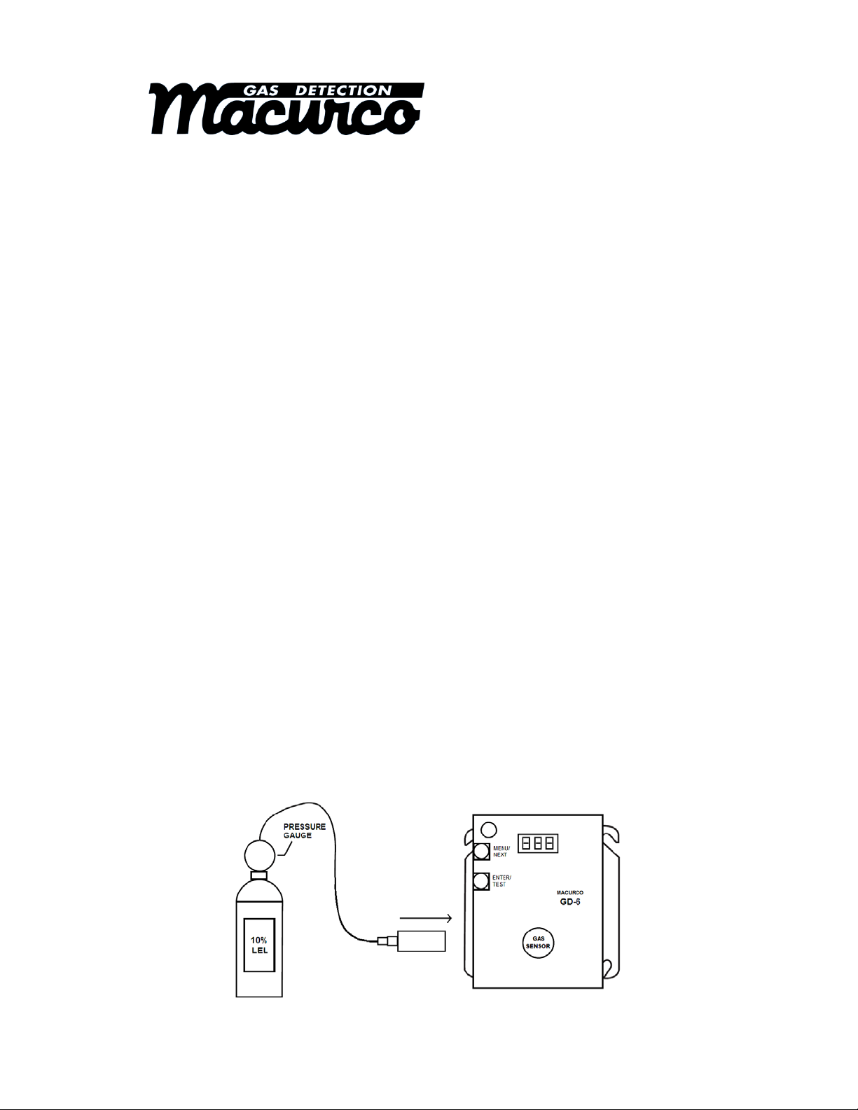
2. Connect the 10% LEL cylinder of Combustibl e Gas to th e regulator. E nsu re that the gas used for ca libratio n matc hes
the gas selected in the GD-6 configuration.
3. Assemble regulator, hose and test hood and place the test hood over the gas sensor.
4. Check the pressure gauge on the regulator. If you have 25-psi or less you will need to replace the g as canister.
Note: The time to activate the fan relay depends on the delay setting.
1
Page 2

5. Turn on the regulator to start the gas flow and wait with the gas applied continuously.
6. With the display function turned “On”, the GD-6 will show the current concentration of gas or “0” (zero) in
clean air. When the gas concentration reaches the fan relay setting (5% LEL, for example) the display will
flash back and forth between “FAn” and “5”. With the display function turned ”Off”, the display does not
show the gas concentration, but will show “FAn” as long as the fan relay is activated.
Note: If the Fan relay does not close within 2 minutes, consider these possibilities:
a. Gas cylinder is empty, check the pressure gauge. Replace the gas cylinder if 25-psi or less.
b. Unit needs to be re-calibrated (go through recalibration and re-test).
c. Detector is in need of servicing (return unit to factory for servicing).
d. Detector has fan relay set to disable (OFF) or 20% LEL. Set fan relay to 5% LEL and repeat the
test.
7. Remove the gas from the sensor. Proceed to test the alarm relay or replace the top cover.
Testing the Alarm Relay
Note: The gas concentration to activate the Alarm relay depends on the setting.
Connect the 20% LEL cylinder of Combustible Gas to the regulator. Ensure that the gas used for calibration
matches the gas selected in the GD-6 configuration.
1. Check the pressure gauge. If there is 25-psi or less the cylinder should be replaced.
2. Place the test hood over the gas sensor. Turn on the regulator to start the gas flow.
3. The Fan relay should activate according to the settings.
4. With the display function turned “On” and the gas concentration reaching the Alarm Relay setting, (20%
LEL, for example) the display will flash back and forth between “ALr” and “20”. The buzzer will sound
indicating “Alarm” if the buzzer is turned “On”. With the display function turned off the display does not
show the gas concentration, but will show “ALr” when the Alarm relay is activated.
5. Note: If the Alarm relay fails to operate within 2 minutes, consider these possibilities:
a. Gas cylinder is empty, check the pressure gauge. Replace the gas cylinder if 25-psi or less.
b. Unit needs to be re-calibrated (go through recalibration and re-test).
c. Detector is in need of servicing (return unit to factory for servicing).
d. Detector has Alarm relay set to disable (OFF). Set Alarm relay to 20% LEL and repeat the test.
6. Remove the gas from the sensor after test. Proceed to test the 4-20 mA output or replace the top cover.
Testing the 4-20 mA current loop
Connect the 20% LEL cylinder of Combustible Gas to the regulator. Ensure that the gas used for calibration
matches the gas selected in the GD-6 configuration.
1. Check the pressure gauge. If there is 25-psi or less the cylinder should be replaced.
2. Place the test hood from the regulator over the gas sensor. Turn on the regulator to start the gas flow.
3. The fan relay should activate according to the settings.
4. The alarm relay should activate according to the settings.
5. The 4-20 mA output should ramp up from 4mA in clean air to 20 mA at 50% LEL. See 4-20 mA diagram in
these User Instructions.
Note: If the 4-20mA output does not ramp up within 2 minutes, consider these possibilities:
a. Gas cylinder is empty, check the pressure gauge. Replace the gas cylinder if 25-psi or less.
b. Unit needs to be re-calibrated (go through recalibration and re-test).
c. Detector is in need of servicing (return unit to factory for servicing).
d. Detector has 4-20 mA option set to “OFF”. Set 4-20 mA option to “On” and repeat the test.
6. Remove the gas from the sensor. Re-assemble the GD-6 (make sure the LED is aligned with the hole on
the front of the case).
2
Page 3

Quick Gas Test
A cigarette lighter can be used to perform a functionality test of the GD-6. This test allows installers to do a
quick functionality test of the gas sensor.
1. Units to be tested must be powered continuously for a minimum of 3 minutes before proceeding.
2. For optimum test results, the unit should be in clean air and be in a low ambient air flow.
3. Check that the GD-6 status indicator light is illuminated, green continuously. If not, do not proceed with
tests. See GD-6 Trouble Indicator section in these User Instructions.
4. The display option should be set to “On” and reading 0% LEL in clean air.
5. Aim the lighter into the sensor grate area (under “DO NOT PAINT”) on the front cover and release the gas
without igniting the flame for 2 to 3 seconds.
6. Wait for a few seconds. The digital display should climb indicating the increased gas concentration at the
sensor confirming a pass of the quick test.
Note: If the Display does not change within 10 seconds, consider these possibilities:
a. Lighter is empty.
b. Unit needs to be re-calibrated (go through the Field Calibration Procedure in these User
Instructions and re-test).
c. Detector is in need of servicing (return unit to factory for servicing).
7. Wait for the display to return to 0% LEL and configure options to desired settings.
FIELD CALIBRATION PROCEDURE
Note: For optimum calibration results the unit should be in clean air and be in a low ambient air flow.
Zero the Sensor
1. Remove the Philips screw on the front of the GD-6. Pull the front cover of the unit off.
2. To select Calibration Zero Mode (000), from normal mode, press the Next button four times to get to CAL or
Calibration Mode.
3. Then press the Enter button to get to “000” - Calibration Zero Mode.
4. Press the Enter button and the display will read 0 alternating with 000 (blinking) ind icating zero calibration in
progress (max 165 sec).
5. If the process is successful, the display will read __0 alternating with PAS (blinking) Zero Calibration complete.
6. If the process was not successful the display will read __1 alternating with Fail (blinking) Zero Failed. If this occurs,
repeat steps 2 through 4. If the sensor fails to zero twice c ontact Technical Assistance: 1-877-367-7891.
7. To return to Normal Mode press Enter and then press Next until “End” is displayed. Press Enter to return to Normal
Mode.
3
Page 4

Calibration
1. Remove the Philips screw on the front of the GD-6. Pull the front cover of the unit off.
2. Assemble the 10% LEL gas cylinder and regul ator toget her. Ensur e th at the gas us ed for calibr ati on m at ches the ga s
that the GD-6 is configured to (mE, Pro or Hy).
3. Check the pressure gauge on the regulator. If you have 25-psi or less you will need to replace the g as canister.
4. Place the test Hood from the regulator over the gas se nsor.
5. To select Calibration Span Mode (SPn), from normal mode, press the Next button four times to get to CAL or
Calibration Mode.
6. Then press the Enter button to get to “000” Calibration Zero Mode, then press the Next button to get to “SPn” –
Calibration Span Mode.
7. Press the Enter button and the display will read 10 alternating with the gas, mE, Pro or Hy (blinking), indicating the
sensor is looking for gas.
8. Start applying gas to the gas sensor.
Note: The sensor will look for the gas for 45 seconds. If no gas is applied or detected in that time, the display
will return to CAL.
9. When the sensor detects the gas, the display will flas h back and forth between the gas concentration and SPn and
the calibration will progress. The dis play will show this for a maximum of 165 seconds.
10. When the calibration is successful, the display will flash back and forth between 10 and PAS.
11. Remove the gas. The display will return to “SPn”, then normal mode. The calibration is done.
12. If the calibration fails, the display will flash back an d forth between the gas concentration and FAL (fail). If this
occurs, check the pressure gauge on the regulator. If the pressure i s le ss than 25-psi the flow of gas may not be
adequate to properly calibrate the unit. If there is proper pressure in the cylinder repeat steps 4 through 11. If the unit
fails to calibrate twice contact Macurco Technical Assistance at 1-877-367 - 7891.
13. Disassemble the cylinder and regulator.
14. Re-assemble the GD-6 (make sure the LED is aligned with the hole in the front case).
MACURCO FIXED GAS DETECTION PRODUCTS LIMITED WARRANTY
Macurco, warrants the field test kits will be free from defective materials and workmanship for a period of one
(1) years from date of manufacture (indicated on the gas bottle label), provided it is maintained and used in
accordance with Macurco instructions and/or recommendations. If any component becomes defective during
the warranty period, it will be replaced or repaired free of charge, if the unit is returned in accordance with the
instructions below. This warranty does not apply to units that have been altered or had repair attempted, or that
have been subjected to abuse, accidental or otherwise. The above warranty is in lieu of all other express
warranties, obligations or liabilities. THE IMPLIED WARRANTIES OF MERCHANTABILITY AND FITNESS
FOR PARTICULAR PURPOSE ARE LIMITED TO A PERIOD OF ONE (1) YEARS FROM THE PURCHASE
DATE. Macurco shall not be liable for any incidental or consequential damages for breach of this or any other
warranty, express or implied, arising out of or related to the use of said gas detector. Manufacturer or its
agent’s liability shall be limited to replacement or repair as set forth above. Buyer’s sole and exclusive remedies
are return of the goods and repayment of the price, or repair and replacement of non-conforming goods or
parts.
Manufactured by Aerionics, Inc.
Round Rock, Texas
Email: info@aerionicsinc.com
Phone: 1-877-367-7891
Rev 4.10.2012
© Aerionics 2012. All rights reserved.
Macurco is a trademark of Aerionics, Inc.
4
 Loading...