

Page 1
Macurco™ DVP-120C
Detection and Ventilation Control Panel with BACnet
User Instructions
IMPORTANT: Keep these user instructions for reference.
Page 2

Macurco DVP-120C Manual
REV – 1.0 [34-8708-4770-8 ] 2 | Page
Page 3

Macurco DVP-120C Manual
Table of Contents
1 General Safety Information ...................................................................................................................................... 7
1.1 List of warnings ................................................................................................................................................. 7
2 Use Instructions and Limitations .............................................................................................................................. 8
2.1 DVP-120C General Description ......................................................................................................................... 8
2.2 DVP-485B Modbus® Adapter ........................................................................................................................... 8
2.3 MRS-485 Modbus Adapter ............................................................................................................................... 8
2.4 Features ............................................................................................................................................................ 9
2.5 Specifications .................................................................................................................................................... 9
3 Installation Instructions .......................................................................................................................................... 10
3.1 Location & Mounting ...................................................................................................................................... 10
3.2 Installation ...................................................................................................................................................... 11
3.2.1 General Wiring Information ................................................................................................................... 11
3.2.2 Power Connection .................................................................................................................................. 12
3.2.3 Remote Sensor Connection .................................................................................................................... 13
3.2.4 Relay Connection .................................................................................................................................... 15
3.2.5 Horn & Strobe Connection ..................................................................................................................... 16
3.2.6 Interfacing Macurco Sensors .................................................................................................................. 16
4 Operations .............................................................................................................................................................. 22
4.1 Power up......................................................................................................................................................... 22
4.2 Initial Operating Mode ................................................................................................................................... 22
4.2.1 Status Light Display ................................................................................................................................. 22
4.3 User Interface ................................................................................................................................................. 23
4.3.1 Cursor Keys ............................................................................................................................................. 23
4.3.2 MENU Key ............................................................................................................................................... 24
4.3.3 Hush Key ................................................................................................................................................. 24
4.4 Normal Status Display .................................................................................................................................... 24
4.5 ALARM Status Display ..................................................................................................................................... 25
4.6 Warning Status Display ................................................................................................................................... 26
4.7 Trouble Status Display .................................................................................................................................... 26
4.8 Unoccupied Failure Display ............................................................................................................................ 27
4.9 Occupied Failure Display ................................................................................................................................ 28
4.10 Calibration Due Warning Display .................................................................................................................... 28
REV – 1.0 [34-8708-4770-8 ] 3 | Page
Page 4

Macurco DVP-120C Manual
4.11 Calibration Overdue Trouble Display ............................................................................................................. 29
4.12 Ventilation Control ......................................................................................................................................... 30
4.12.1 Zone Signal Display ................................................................................................................................. 30
4.13 System Configuration ..................................................................................................................................... 31
4.13.1 System Menu .......................................................................................................................................... 32
4.13.2 Configure System Submenu ................................................................................................................... 32
4.13.3 Configure Sensors Submenu ................................................................................................................... 40
4.13.4 Configure Relays, Horn & Strobe Submenu............................................................................................ 42
4.13.5 Configure Horn Submenu ....................................................................................................................... 43
4.13.6 Configure Strobe Submenu .................................................................................................................... 43
4.13.7 Configure Zones Submenu ..................................................................................................................... 44
4.13.8 Configure Signals Submenu .................................................................................................................... 48
5 BACnet .................................................................................................................................................................... 52
5.1 General Information ....................................................................................................................................... 52
5.1.1 Analog input – Sensor ID ........................................................................................................................ 52
5.1.2 Analog Input – Gas Reading .................................................................................................................... 52
5.1.3 Binary Input – MRS Trouble .................................................................................................................... 52
5.1.4 Binary Input – Over Range ...................................................................................................................... 52
5.1.5 Binary Input – Trouble ............................................................................................................................ 52
5.1.6 Binary Input – DVP Com Error ................................................................................................
................ 52
5.2 Macurco Network Parameter Utility (NPU) .................................................................................................... 52
5.3 BACnet Connection ......................................................................................................................................... 54
5.3.1 Serial RS-485 to USB Wiring ................................................................................................................... 55
5.3.2 BACnet MS/TP to BACnet/IP................................................................................................................... 56
5.4 BACnet Software ............................................................................................................................................ 56
6 Troubleshooting ..................................................................................................................................................... 56
6.1 System Status Light......................................................................................................................................... 56
6.1.1 Input Channel Trouble ............................................................................................................................ 57
6.1.2 Internal Controller board Trouble .......................................................................................................... 58
6.2 Timed Ventilation Problem ............................................................................................................................ 58
6.3 No Power ........................................................................................................................................................ 58
6.4 LCD Display Unreadable ................................................................................................................................. 58
6.5 Keypad does not respond ............................................................................................................................... 59
REV – 1.0 [34-8708-4770-8 ] 4 | Page
Page 5

Macurco DVP-120C Manual
6.5.1 LCD shows KEYS LOCKED ........................................................................................................................ 59
6.5.2 After silencing Alarm, Warning or Trouble ............................................................................................. 59
6.6 Power Failure .................................................................................................................................................. 59
6.7 MRS-485 Modbus Application ........................................................................................................................ 59
6.7.1 Normal Operation ................................................................................................................................... 59
6.7.2 Unknown Sensor Code ........................................................................................................................... 59
6.7.3 Error Codes ............................................................................................................................................. 59
6.7.4 Dip Switch Settings Codes ...................................................................................................................... 60
7 Testing & Maintenance .......................................................................................................................................... 61
7.1 Testing ............................................................................................................................................................ 61
7.1.1 Keypad Test ............................................................................................................................................ 61
7.1.2 Functionality Test ................................................................................................................................... 61
7.2 Maintenance ................................................................................................................................................... 62
8 Appendix A – Table of Figures ................................................................................................................................ 63
9 Appendix B – Quick Setup ...................................................................................................................................... 67
9.1 Configure System Submenu ........................................................................................................................... 70
9.1.1 Set Time of Day ....................................................................................................................................... 70
9.1.2 Set Day of Week ..................................................................................................................................... 70
9.1.3 Load Default Configuration .................................................................................................................... 70
9.1.4 Change Password.................................................................................................................................... 70
9.1.5 Enter Password ....................................................................................................................................... 71
9.2 Configure Sensors Submenu........................................................................................................................... 71
9.2.1 See section 4.2 Initial Operating Mode for more detail ......................................................................... 71
9.2.2 See section 4.3 User Interface for more detail ....................................................................................... 71
9.2.3 See section 4.13 System Configuration for more detail ......................................................................... 71
9.2.4 See section 4.13.3 Configure Sensors Submenu for more detail ........................................................... 71
9.3 Configure Relays, Horn & Strobe Submenu ................................................................................................... 72
9.3.1 See section 4.13.4 Configure Relays, Horn & Strobe Submenu for more detail .................................... 72
9.4 Configure Zones Submenu ............................................................................................................................. 73
9.4.1 See section 4.13.7 Configure Zones Submenu for more detail .............................................................. 73
9.5 Configure Signals Submenu ............................................................................................................................ 75
9.5.1 See section 4.13.8 Configure Signals Submenu for more detail ............................................................ 75
10 Appendix C – Setup Record ................................................................................................................................ 76
REV – 1.0 [34-8708-4770-8 ] 5 | Page
Page 6

Macurco DVP-120C Manual
11 Appendix D – DVP-120 Quick Start Guide .......................................................................................................... 77
12 Macurco Gas Detection Product limited warranty ............................................................................................. 80
Technical Support Contact Information ....................................................................................................................... 80
General Contact Information ........................................................................................................................................ 80
REV – 1.0 [34-8708-4770-8 ] 6 | Page
Page 7

WARNING
Each person using this equipment must read and understand the information in this
adversely affect product
performance.
This equipment helps monitor for the presence and concentration level of certain
sent and could result in
Support at 1-844-325-3050.
DVP-120C may not function effectively below 32°F (0°C) or above 120°F (49°C). Using
the equipment outside of this temperature range may adversely affect product.
High voltage terminals (120/240 VAC) are located within the DVP-120C, presenting a
servicing the unit.
Immediately exit any environment that causes an alarm condition on the sensor.
Each time the unit is turned on it performs a self-test, which activates the audible and
contact Technical Support at 1-844-325-3050.
Do not cover or obstruct audible alarm opening or visual alarm LED. Doing so may
adversely affect product performance.
Use only for monitoring the gases which the sensors and equipment are designed to
roper use, see supervisor or User manual, or Contact
Technical Support at 1-844-325-3050.
Failure to follow instructions outlined in this user manual can result in sickness or death.
Macurco DVP-120C Manual
1 General Safety Information
1.1 List of warnings
User manual before use. Use of this equipment by untrained or unqualified persons or
use that is not in accordance with this user manual, may
specified airborne gases. Misuse may produce an inaccurate reading, which means that
higher levels of the gas being monitored may be pre
overexposure. For proper use, see supervisor or User manual, or call Macurco Technical
hazard to service technicians. Only qualified technicians should open the DVP-120C case
and service the internal circuits. Ensure power is removed from the DVP-120C prior to
visual alarms. If the self-test fails, or all the alarms do not activate, do not use and
detect. Failure to do so may result in exposures to gases not detectable and result in
serious injury or death. For p
REV – 1.0 [34-8708-4770-8 ] 7 | Page
Page 8
WARNING
Each person using this equipment must read and understand the information in this
l, may adversely affect product
performance.
Macurco DVP-120C Manual
2 Use Instructions and Limitations
2.1 DVP-120C General Description
The DVP-120C is an exhaust fan controller and alarm interface. When used in conjunction with Macurco gas
detectors, it provides automatic controls to help maintain an acceptable environment in enclosed facilities. The DVP120C is frequently used in parking garages, warehouses, and vehicle maintenance facilities. The DVP-120C system is
designed to meet specifications for safety in enclosed parking garages, including the Uniform Building Code and
OSHA 50ppm CO requirements. The standard DVP-120C can control up to 99 digital addressable sensors and is
compatible with Macurco CM-6 and TX-6-ND detectors ONLY. The DVP-120C is ready for operation after the wiring is
complete and the user system configuration is entered.
2.2 DVP-485B Modbus® Adapter
The DVP-485B Modbus adapter, installed in DVP-120C, provides a RS-485 BACnet output. System wiring includes RS485 serial detector interface as well as main power connection for the DVP-120C, the fan control and alarm
connections from the DVP-120C to the building ventilation and automation systems. The RS-485 serial interface is
from the DVP-120C to the remote detectors. Power to these detectors is provided by an external 24VAC or VDC low
voltage power supply. See section 3.2.3 Remote Sensor Connection
supplies.
for more information regarding remote power
2.3 MRS-485 Modbus Adapter
The Macurco MRS-485 adapter is an accessory used to convert the 4-20mA analog signal from Macurco 6-Series
type detectors to a digital signal for use with the DVP-120C and other multipoint addressable systems. The Macurco
MRS-485 simply plugs into the back of the detector and a single screw fastens it in place. The MRS-485 accepts the
4-20mA output and is powered from the same connection as the detector. The MRS-485 mounts to a Macurco 6Series detector installed on a 4”x 4” electrical box electrical box supplied by the contractor.
User manual before use. Use of this equipment by untrained or unqualified persons or
use that is not in accordance with this user manua
REV – 1.0 [34-8708-4770-8 ] 8 | Page
Page 9

Macurco DVP-120C Manual
2.4 Features
• LCD display showing the status of each transducer and relay
• External keypad for user selection of the transducer/alarm display and setting the configuration (password
protected)
• Up to three ventilation control zones can be defined
• Each zone can be controlled based on transducer signals and/or time of day
• Each relay is configurable with a delay before activation and minimum on time
• Fail-safe operation can be implemented
• Lockable NEMA 1 type enclosure
• Modular input and output connectors
• One RS-485 digital input channels - 99 addressable sensors
• RS-485 digital output channel for BACnet
• Compatible with Macurco CM-6, TX-6-ND, and MRS-485 adapter, Horn & Strobe Combo
• Three 10A, 240 VAC SPDT Dry Contact relays
• 24VDC Drivers for external Horn and Strobe
• BTL Listed
1
• ETL Listed to UL 2017
1
Where required by federal, state, local regulations or the Authority Having Jurisdiction, DVP-120C is required to be used with Listed
Horn/Strobe model 78-2900-0211-X* to meet the 85dB(A) Audibility requirements of Standards UL 2017.
*Where “X” represents lens cover color, R for red lens cover, G for green lens cover, B for blue lens cover, O for amber lens cover, C for
clear lens cover.
(Type SM)
2.5 Specifications
• Size: 10.5” x 12.5” x 2.” (267 mm x 318 mm x 51 mm)
• Weight: 6 ½ lb (2.9 kg)
• Enclosure: NEMA 1 Type
• Operating Temperature: 32° to 120°F (0° to 49°C)
• Operating Humidity: 0% to 90% RH non-condensing
• Power Input: 90 – 250 VAC, 1 Amp, 47 – 63 Hz, single phase
• Relay Rating (3): SPDT, 120/240 VAC, 10 A resistive
• LCD Display: 2 rows of 16 characters with backlight
• Status Indicators (LED): Power/Trouble, ALARM/warning, Hush, Relay 1, Relay 2 & Relay 3
• Audible indicator: Internal buzzer, 90 dBA at 1ft
• External Drivers (2): 24VDC, maximum 250 mA
• Carbon Monoxide (CO) Range: 0 – 200ppm
• Nitrogen Dioxide (NO2) Range: 0 – 20ppm
• Relay on Delay: 0 – 15 minutes in 1 second increments
• Relay Minimum Run Time: 0 – 15 minutes in 1 second increments
REV – 1.0 [34-8708-4770-8 ] 9 | Page
Page 10

WARNING
This equipment helps monitor for the presence and concentration level of certain
higher levels of the gas being monitored may be present and could result in
Service at 1-844-325-3050.
WARNING
DVP-120C may not function effectively below 32°F (0°C) or above 104°F (40°C). Using
the equipment outside of this temperature range may adversely affect product.
Macurco DVP-120C Manual
3 Installation Instructions
Gas detection and exhaust fan control are provided by a Macurco DVP-120C system. System wiring includes the
main power connection for the DVP-120C, the fan control connections and/or alarm connections from the DVP-120C
to the building ventilation and automation systems. The DVP-120C also includes the RS-485 serial interface from the
DVP-120C to the MRS-485 and remote detectors. Power to the MRS-485 and detectors is provided by
isolated/remote low voltage power supply.
The system is configured by the user through the LCD display and keypad. The system display provides the user with
the system status and the status of each configured sensor. In addition, all control functions of the DVP-120C may be
accessed through the system display and keypad.
specified airborne gases. Misuse may produce an inaccurate reading, which means that
overexposure. For proper use, see supervisor or User manual, or call Macurco Technical
This DVP-120C system should be used with Macurco™ CM-6 and TX-6-ND transducers and each unit will measure
the level of the target gas (i.e. CO, and NO
communication loop. The transducers operate on low voltage (24VDC). All power and signal connections for the
transducers are provided via unshielded two conductor cable from an external power source. DVP-120C Modbus
applications use shielded 3-conductor wire with one twisted pair providing a pair for signal (A & B), common (COM)
and shield ground (SHD) connections. The DVP-120C control panel provides three relays which can be used for
ventilation fan control or alarm signaling. These relays (SPDT - Form C) are for pilot duty only, capable of switching
10 amp loads up to 240 VAC. Main power wiring should conform to national and local electrical codes and may
require separate inspections and certification. Contact your local building authority for further details.
) and provide this information to the DVP-120C over Modbus
2
3.1 Location & Mounting
The DVP-120C should be installed in a centralized location, easy to access and protected weather and other
environmental elements. DVP-120C is intended for indoor use only. A Mechanical room, Alarm Control Room or
other similar areas are recommended.
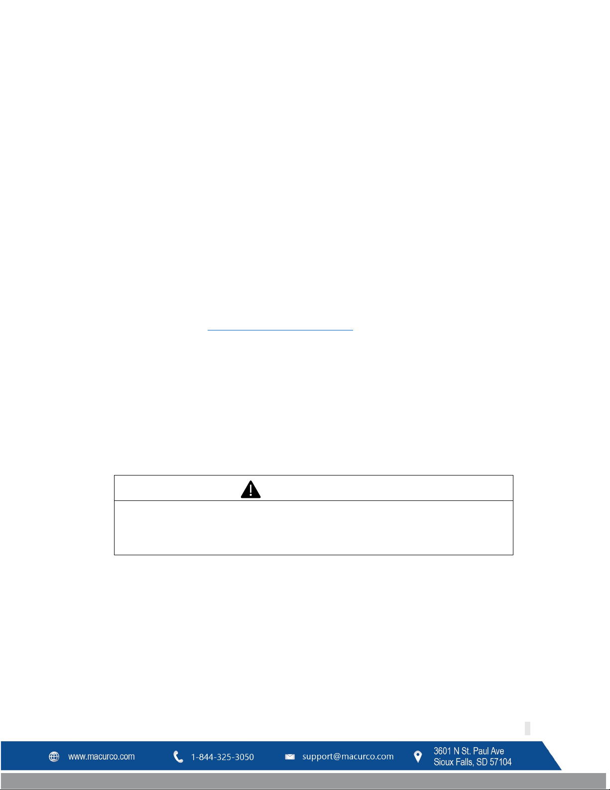
Mounting holes are provided in the DVP-120C case at the four corners. The top two are keyhole shaped so that the
panel can be hung and then the two bottom screws driven to hold the panel. See figure 3-1. The panel should be
mounted with sufficient space around the panel for access to conduit entry holes provided on the top, bottom and
right side of the panel.
REV – 1.0 [34-8708-4770-8 ] 10 | Page
Page 11
WARNING
High voltage terminals (120/240 VAC) are located within the DVP-120C, presenting a
servicing the unit.
Macurco DVP-120C Manual
3.2 Installation
Figure 3-1 Mounting Holes
3.2.1 General Wiring Information
hazard to service technicians. Only qualified technicians should open the DVP-120C case
and service the internal circuits. Ensure power is removed from the DVP-120C prior to
Figure 3-2 Typical Layout
REV – 1.0 [34-8708-4770-8 ] 11 | Page
Page 12

Signal
Connector
Pin Number
Line (120/220/240/250 VAC)
AC~ 3 Neutral
AC~ 1 Ground
Ground Stud
n/a
Macurco DVP-120C Manual
With the exception of the safety ground, all field wiring is completed via modular connectors (provided). After
wiring, simply plug the modular connectors into the matching connectors on the printed circuit board (PCB).
Note: It is recommended to always install with wires enclosed within the rigid metallic conduit.
The power and signal connections to the remotely mounted sensors should be size AWG18 (minimum) for short
runs. Refer to Table 3-2 for recommended wire gauges.
Do not bundle sensor power and/or signal connections with other AC power cables to prevent electrical
interference. If other AC power connections must be bundled with the DVP-120C sensor cables, the sensor
connections should be made with two twisted pairs of the appropriate gauge, with an overall foil and braid shield.
All shields should be terminated at the DVP-120C end of the cable only. A ground stud is provided.
The power connections to the MRS-485 and remote mounted sensors should be size AWG18 (minimum) for short
runs. Refer to Table 3-2a for recommended wire gauges. The power for the MRS-485 adapter is connected via a twoterminal screw type connector, 12 to 24 VAC or 12 to 24 VDC and no polarity.
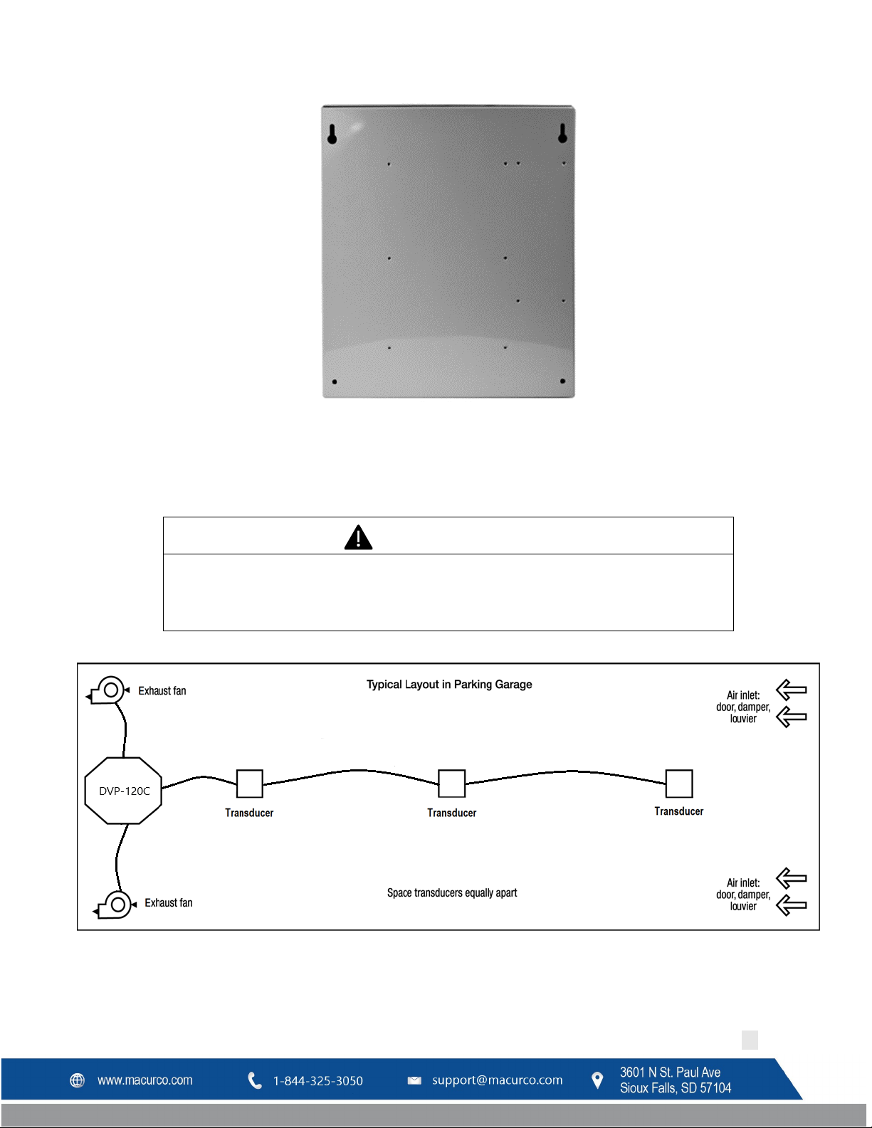
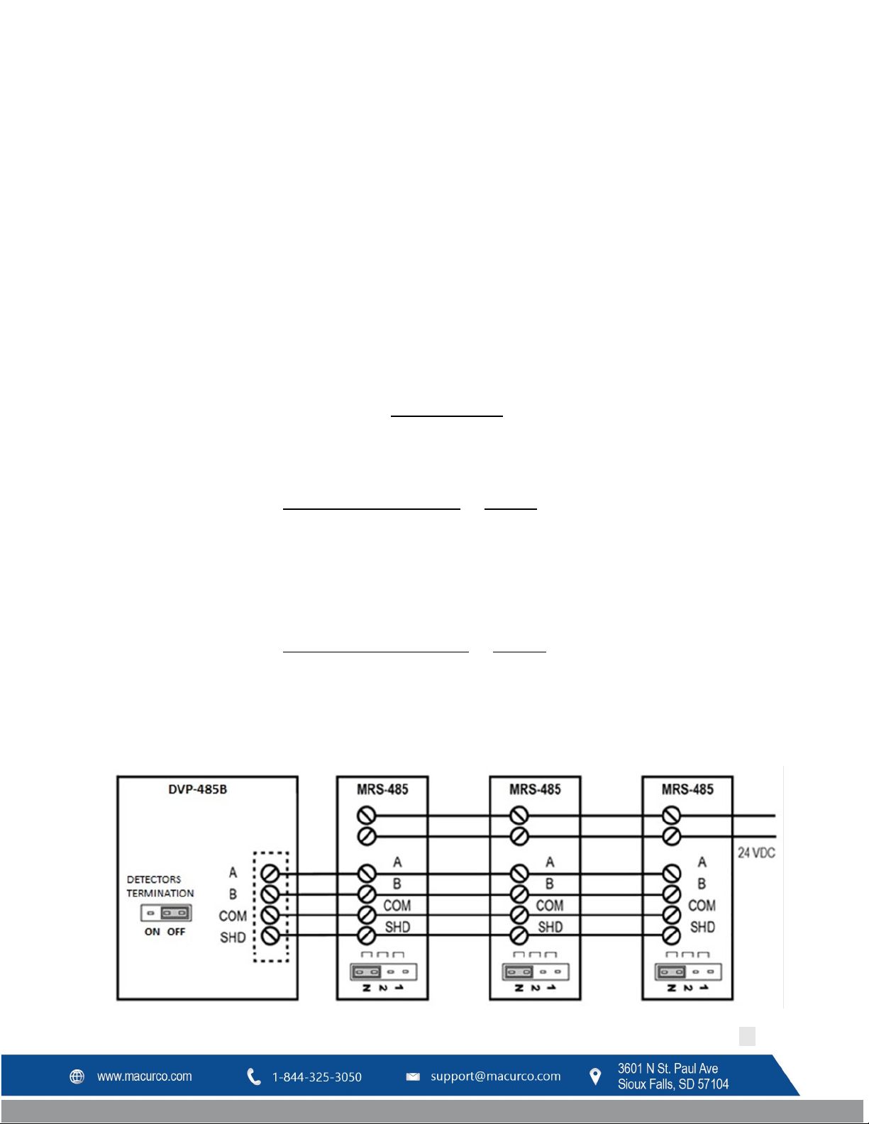
The MRS-485 adapter output is wired in the standard 2W-Modbus circuit definition with selectable built-in
terminating resistors at the ends of the RS-485 bus. It is recommended to always use twisted wires to reduce noise
and allow for reliable data communication over greater distances. For best performance use shielded 3-conductor
wire with one twisted pair providing a pair for signal (A & B), common (COM) and shield ground (SHD) connections.
Use at least 3-conductor wire with one twisted pair providing a pair for signal (A & B) and common (COM)
connections. The Macurco MRS-485 Modbus output is connected via a four-terminal screw type connector.
Running the Modbus cable adjacent to or in the same conduit with high voltage wires is not recommended as there
may be interference from the high voltages near the bottom left corner of the panel.
3.2.2 Power Connection
The main power cable should be routed into the bottom left conduit entry. Macurco recommends a minimum wire
size of AWG18 and the wire insulator must be rated for 140°F (60°C) service. The modular connector will accept wire
from 12 to 24 AWG. The safety ground wire should be secured to the ground stud at the bottom left of the cabinet
with the lock washer and nut supplied. Use a ring terminal for the ground connection. Refer to Table 3-1 for DVP120C power connections. The line and neutral wires should be stripped 1/4 in. (6.5 mm), insert the wire into the
wire cavity of the modular connector and tighten the screw clamp. Ensure that the wire cannot be easily pulled from
the connector. Plug the modular connector into AC~ on the PCB and ensure that it latches into the header properly.
Table 3-1 Main Power Connection
REV – 1.0 [34-8708-4770-8 ] 12 | Page
Page 13

1
2
1 Supervised Circuit
Macurco DVP-120C Manual
2 Non-Supervised Circuit
Figure 3-3 System Wiring Diagram
3.2.3 Remote Sensor Connection
REV – 1.0 [34-8708-4770-8 ] 13 | Page
Figure 3-4 DVP-120C Internal View
Page 14
Macurco DVP-120C Manual
Remote sensors must be connected at RS-485 connection labeled TB1 (Refer Figure 3-10). A Modbus over Serial Line
Cable should be shielded for best performance. The shield should be connected on each detector at SHD terminal
and connected to a ground terminal or chassis only at one end of the bus. An RS485-MODBUS must use a balanced
pair (for A-B) and a third wire (for the Common). For RS485-MODBUS, Wire Gauge must be chosen sufficiently wide
to permit the maximum length (1000 m or 3281ft). AWG 24 is always sufficient for the MODBUS Data. Category 5
cables may operate for RS485-MODBUS, to a maximum length of 600 m 1968.5 ft. For the balanced pairs used in an
RS485-system, wire with a characteristic impedance of higher than 100 Ohms may be preferred, especially for 19200
and higher baud rates.
Note: It is recommended to always use twisted wires to reduce noise and allow for reliable data communication
over greater distances. Use at least 3-conductor wire with one twisted pair providing a pair for signal (A & B) and
common (COM) connections.
For best performance use shielded 3-conductor wire with one twisted pair providing a pair for signal (A & B),
common (COM) and shield ground (SHD) connections.
Figure 3-6 MRS-485 Wiring
3.2.3.1 Topology
An RS485-MODBUS configuration without repeater has one trunk cable, along which devices are connected, directly
(daisy chaining) or by short derivation cables. The trunk cable, also named “Bus”, can be long. Its two ends must be
connected on Line Terminations. (see Line Termination - End of Line Resistor section). The use of repeaters between
several RS485-MODBUS is also possible.
The DVP-120C has a single Modbus termination block that will accept two trunk cable connections allowing for two
MODBUS communication lines. The Trunk cable must be wired in parallel from the panel to the end of line with no
off shoots “T-tapping”.
3.2.3.2 Length
The end to end length of the trunk cable must be limited. The maximum length depends on the baud rate, the cable
(Gauge, Capacitance or Characteristic Impedance), the number of loads on the daisy chain, and the network
configuration (2-wire). For a maximum 9600 Baud Rate and AWG26 (or wider) gauge, the maximum length is 1000m
3281ft. The derivations must be short, never more than 20m 65.5ft. If a multi-port tap is used with n derivations,
each one must respect a maximum length of 40m 131ft divided by n.
3.2.3.3 Grounding
The Shield (SHD) must be connected directly to protective ground, preferably at one point only for the entire bus.
REV – 1.0 [34-8708-4770-8 ] 14 | Page
Page 15
Wire gauge
Maximum Run Length
(feet)
(meters)
18
263
80
16
418
127
14
665
203
12
1058
322
Macurco DVP-120C Manual
3.2.3.4 Power Wire
All field wiring is completed via modular connectors (provided). After wiring, simply plug the modular connectors
into the matching connectors on the MRS-485. The power connections to the remotely mounted detectors should
be size AWG18 (minimum) for short runs. Since Macurco detectors are rated for operation between 12 and 24 VDC
or VAC, the voltage drop between the power supply and the MRS-485 should not be an issue if the recommended
power wire gauge guidelines in are followed. The terminals will accept wire from 16 to 28 AWG. To install a wire,
strip back approximately 0.25 in. (6 mm) of insulation and insert the bare wire into the terminal. Tighten the screw
clamp and ensure that the wire cannot be easily pulled from the connector.
3.2.3.5 External Power Supply
Select a UL recognized NEC Class 2 power supply which can power the MRS-485 units connected to 6-Series
detectors.
• Each MRS-485 is rated at 3.25W with a detector connected.
• The minimum power which the power supply needs to deliver for 12 detectors is figured as:
12 detectors x 3.25 W per detector = 39W
• Therefore, a 24VDC, 60W power supply will work.
Table 3-2 Wire selection for a 60W power supply
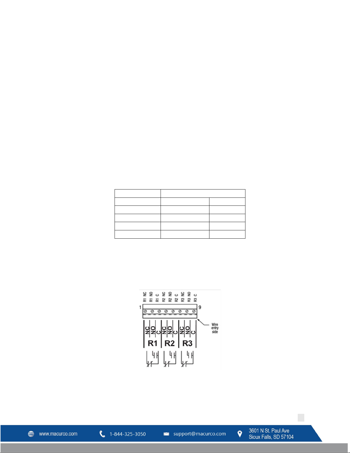
3.2.4 Relay Connection
All poles of the three relays are available at the modular connector R1 R2 R3 (see Figure 2 for details). R1 R2 R3 is a
9-position variant of the high voltage modular connector used for power input. Each terminal can accommodate a
wire size from 12 to 24 AWG.
Figure 3-7 Relay Connector
To install the wiring for the relays, disconnect the connector from the header on the PCB. Strip the insulation off
each wire back approximately 0.25 in. (6.5 mm), insert the bare wire into the terminal and tighten the screw clamp.
Ensure that the wire cannot easily be pulled from the connector.
REV – 1.0 [34-8708-4770-8 ] 15 | Page
Page 16
Maximum Run Length
(feet)
(meters)
24
200
61
22
340
103
20
480
147
18
850
215
WARNING
Immediately exit any environment that causes an alarm condition on the sensor.
Macurco DVP-120C Manual
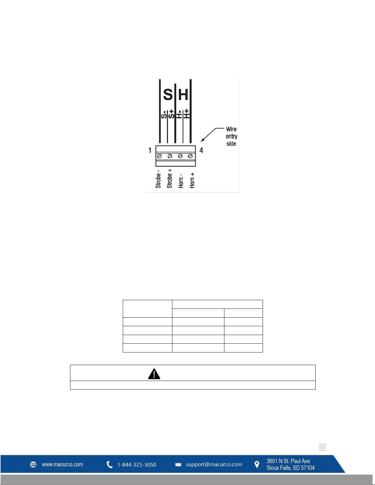
3.2.5 Horn & Strobe Connection
The external horn and strobe connections are available at the modular connector S H (see Figure 2 for details). S H
as a 4-position connector, similar to the sensor interface connectors.
Figure 3-8 Horn & Strobe Connector
To install the wiring for the horn or strobe, disconnect the connector from the header on the PCB. Strip the
insulation off each wire back approximately 0.25 in. (6 mm), insert the bare wire into the terminal and tighten the
screw clamp. Ensure that the wire cannot easily be pulled from the connector. When all wires are connected, seat
the modular connector into the PCB header; ensure that the latch engages. Refer to Table 3-3 for recommended
wire gauge vs. run length for the horn & strobe functions (maximum 2.5-volt drop in the wire). The Strobe and Horn
circuits are Class 2 control circuits, so Class 2 conductors should be used.
For UL 2017, DVP-120C was tested with one Listed Horn/Strobe model 78-2900-0211-X where X represents lens
cover color, R for red lens cover, G for green lens cover, B for blue lens cover, O for amber lens cover, C for clear lens
cover.
Wire gauge
Table 3-3 Wire gauge for Horn & Strobe functions
3.2.6 Interfacing Macurco Sensors
Macurco sensors with current loop outputs may be used with the DVP-120C. See www.macurco.com for information
on compatible Macurco gas transducers. See specific information on other manufacturer’s transducers.
REV – 1.0 [34-8708-4770-8 ] 16 | Page
Page 17
Macurco DVP-120C Manual
Power connections to Macurco sensors used with the DVP-120C are polarity-insensitive (no polarity) since a bridge
rectifier is connected to the power input terminals. All sensors used with the DVP-120C panel employ screw clamp
terminal blocks for power and signal connections. The polarity of the current loop connections is marked on the
printed circuit board of the sensor.
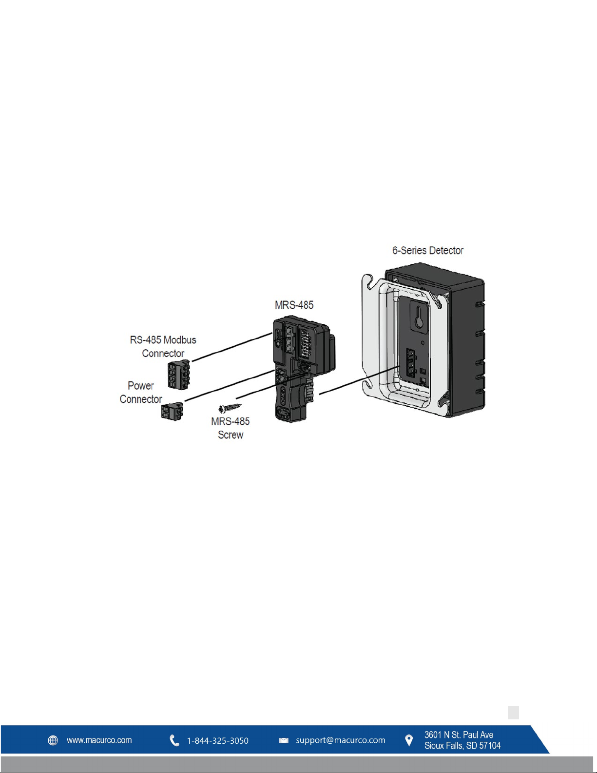
The Macurco MRS-485 Adapter converts the Macurco 6-Series 4-20mA analog output to a digital output for use with
the DVP-120C and other addressable network systems.
1. Remove the 4-20mA/Power plug from the Macurco 6-Series gas detector
2. Plug the MRS-485 adapter into the empty socket.
3. Install the provided MRS-485 screw.
4. See the wiring diagram for wire connection.
Figure 3-9 MRS-485 Installation
3.2.6.1 Connection
The Macurco MRS-485 output is connected via a four-terminal screw type connector. The MRS-485 adapter is wired
in the standard 2W-Modbus circuit definition with selectable built-in terminating resistors at the ends of the RS-485
bus. The power for the MRS-485 adapter is connected via a two-terminal screw type connector, 12 to 24 VAC or 12
to 24 VDC and no polarity.
Note: Running the Modbus cable adjacent to or in the same conduit with high voltage wires is not recommended as
there may be interference from the high voltages.
REV – 1.0 [34-8708-4770-8 ] 17 | Page
Page 18
Macurco DVP-120C Manual
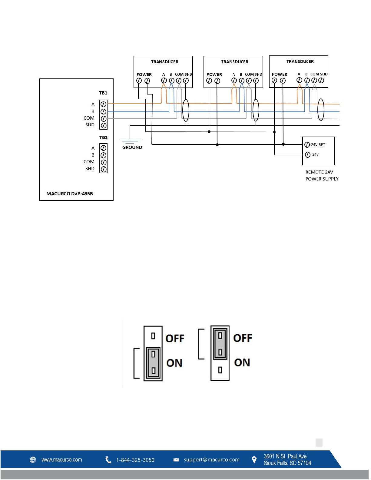
Figure 3-10 Modbus Wiring
3.2.6.2 Line Termination – End of Line Resistor
The MRS-485 and DVP-485B adapters are wired in the standard 2W-Modbus circuit definition with selectable built-in
terminating resistors at the ends of the RS-485 bus. The MRS-485 and DVP-485B adapters provide integral
termination for the end of line resistors (EOL). The terminations use 4-pin connector (for MRS-485) and 3-pin (for
DVP-485B) with a jumper to select termination: The user selects no termination or one of the two Modbus line
termination options. The MRS-485 has two-line termination options provided and DVP-485B adapters have 120-ohm
termination options provided onboard.
Place the EOL jumper on one of the following positions:
Figure 3-11 End of Line Resistor
Determining EOL Use
REV – 1.0 [34-8708-4770-8 ] 18 | Page
Page 19
Macurco DVP-120C Manual
3.2.6.3 Baud Rates
At the baud rate of 19200 (default baud rate for Macurco MRS-485 and DVP-485) and with cables less than 1,000 ft.
in length, termination resistors are not recommended.
At the baud rate of 19200 and with cables longer than 1,000 ft., termination resistors are recommended.
It is recommended to use an RS-485 type of cable and 120 ohms for termination resistor.
An RS-485 network requires a 3-wire cable: a twisted pair and a third wire. It is difficult to tell whether shielding is
required or not in a particular system until problems arise, so it is recommended to always use shielded cable.
When using termination resistors use only 2 resistors, one at each end of the RS-485 transmission line (i.e. 1 at the
DVP-485B and 1 at the last/farthest MRS-485).
For any other baud rates calculate when (at what length) termination resistors are required. This is calculated by
dividing the length L by the ratio between the new baud rate and 19200 or (x/19200) where x is the new baud rate.
( 19200 ⁄)
For example, if new baud rate is 9600
1000
(9600 19200 ⁄)
1000
=
0.5
= 2000
Use termination resistors when cables are longer than 2000 ft.
For example, if new baud rate is 38400
1000
(38400 19200 ⁄)
1000
=
2
= 500
Use termination resistors when cables are longer than 500 ft.
Note: Other manufacturers may have different recommendations on wire length and EOL resistor usage.
REV – 1.0 [34-8708-4770-8 ] 19 | Page
Page 20
1 = 1
21 = 1, 3, 5
41 = 1, 4, 6
61 = 1, 3, 4, 5, 6
83 = 1, 2, 5, 7
2 = 2
22 = 2, 3, 5
42 = 2, 4, 6
62 = 2, 3, 4, 5, 6
84 = 3, 5, 7
3 = 1,2
23 = 1, 2, 3, 5
43 = 1, 2, 4, 6
63 = 1, 2, 3, 4, 5, 6
85 = 1, 3, 5, 7
4 = 3
24 = 4, 5
44 = 3, 4, 6
64 = 7
86 = 2, 3, 5, 7
5 = 1,3
25 = 1, 4, 5
45 = 1, 3, 4, 6
65 = 1, 7
87 = 1, 2, 3, 5, 7
6 = 2,3
26 = 2, 4, 5
46 = 2, 3, 4, 6
66 = 2, 7
88 = 4, 5, 7
7 = 1,2,3
27 = 1, 2, 4, 5
47 = 1, 2, 3, 4, 6
67 = 1, 2, 7
89 = 1, 4, 5, 7
8 = 4
28 = 3, 4, 5
48 = 5, 6
68 = 3, 7
90 = 2, 4, 5, 7
9 = 1,4
29 = 1, 3, 4, 5
49 = 1, 5, 6
69 = 1, 3, 7
91 = 1, 2, 4, 5, 7
Macurco DVP-120C Manual
Figure 3-12 EOL Placement Less than 1000 ft
At 19200 baud rate (default), 1000 ft or less and using RS-485 or Cat-5 type cable
Figure 3-13 EOL Placement greater than 1000 ft
At 19200 baud rate (default), more than 1000 ft and using RS-485 type cable
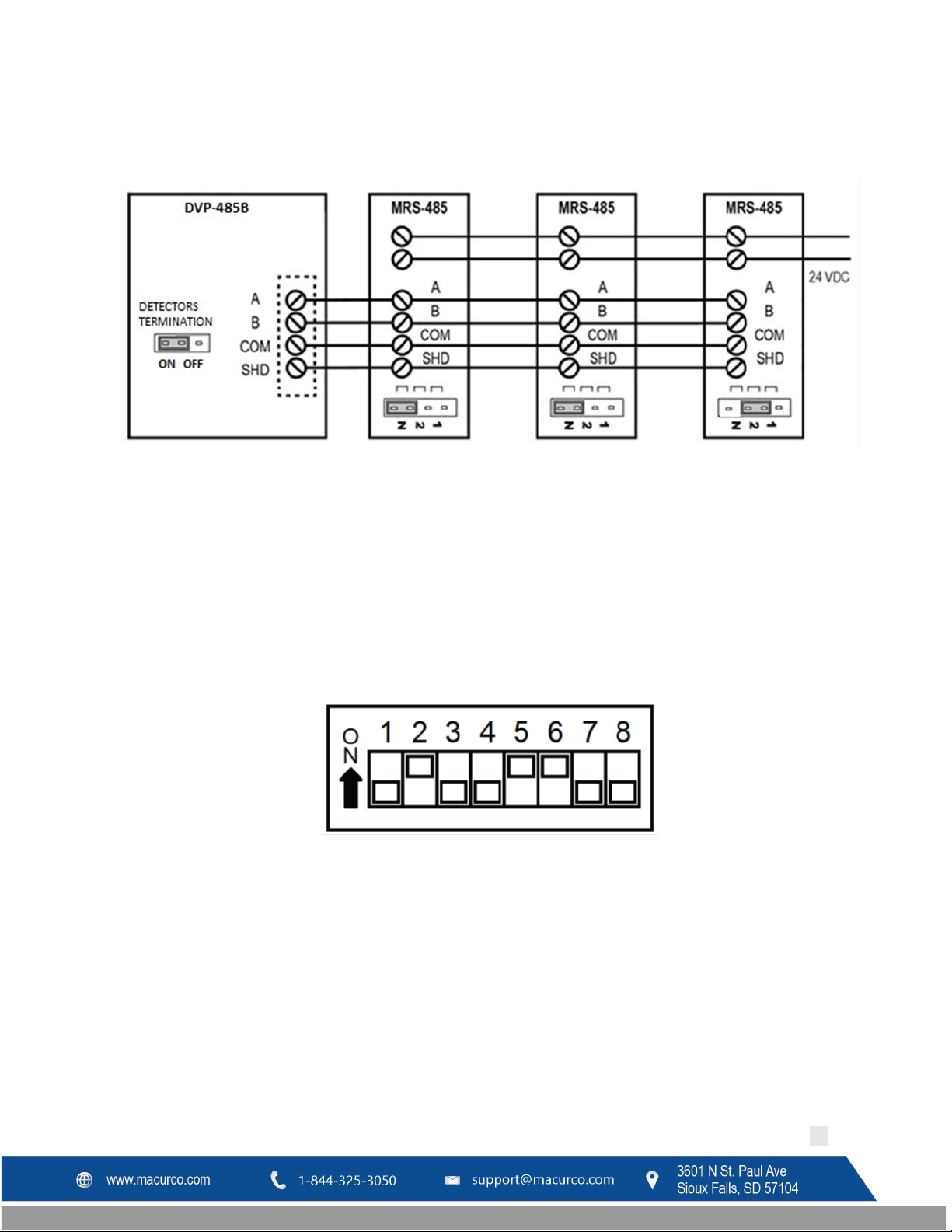
3.2.6.4 Dip Switches and Addressing
Each MRS-485 (and the partner gas detector) must be configured to a unique address. If there are 10 detectors on
the serial line, then 10 unique addresses must be used, one for each detector. To set the address, use the eight DIP
switch positions. For each unit choose the value from 1 to 99 (see chart) and set the eight switches to match the
address. UP means ON or 1 and DOWN means OFF or 0. For example, to configure a unit as address “50”, set
switches “2, 5, 6” (see table) to ON or in the up position (01001100). See page 11 for a list of applicable addresses
and dip-switch settings.
Figure 3-14 MRS-485 Dip Switch (Address “50” Shown)
REV – 1.0 [34-8708-4770-8 ] 20 | Page
Page 21

10 = 2,4
30 = 2, 3, 4, 5
50 = 2, 5, 6
70 = 2, 3, 7
92 = 3, 4, 5, 7
11 = 1,2,4
31 = 1, 2, 3, 4, 5
51 = 1, 2, 5, 6
71 = 1, 2, 3, 7
93 = 1, 3, 4, 5, 7
12 = 3,4
32 = 6
52 = 3, 5, 6
72 = 4, 7
94 = 2, 3, 4, 5, 7
13 = 1, 3,4
33 = 1, 6
53 = 1, 3, 5, 6
73 = 1, 4, 7
95 = 1, 2, 3, 4, 5, 7
14 = 2, 3, 4
34 = 2, 6
54 = 2, 3, 5, 6
74 = 2, 4, 7
96 = 6, 7
15 = 1, 2, 3, 4
35 = 1, 2, 6
55 = 1, 2, 3, 5, 6
75 = 1, 2, 4, 7
97 = 1, 6, 7
16 = 5
36 = 3, 6
56 = 4, 5, 6
76 = 3, 4, 7
98 = 2, 6, 7
17 = 1, 5
37 = 1, 3, 6
57 = 1, 4, 5, 6
77 = 1, 3, 4, 7
99 = 1, 2, 6, 7
18 = 2, 5
38 = 2, 3, 6
58 = 2, 4, 5, 6
78 = 2, 3, 4, 7
19 = 1, 2, 5
39 = 1, 2, 3, 6
59 = 1, 2, 4, 5, 6
79 = 1, 3, 4, 7
20 = 3, 5
40 = 4, 6
60 = 3, 4, 5, 6
80 = 5, 7
Macurco DVP-120C Manual
Table 3-4 Dip switch settings
3.2.6.5 Normal MRS-485 Operation
The MRS-485 will monitor the 4-20 mA current output of the detector. At power up and during its warm-up period,
the 6-Series detector will communicate its sensor type over the 4-20 current output using a custom protocol. The
MRS-485 will automatically register each 6-Series detector as it is programmed with information about all the
detectors to which it can be connected. The MRS-485 will use this information to determine the gas level sensed by
the 6-Series detector by measuring the 4-20 mA current-loop output during normal operation of the detector.
• When the LED is solid GREEN, the operation is normal, the MRS-485 knows the detector type, no errors are
detected, and no MODBUS data are being received or transmitted over the RS-485 line.
• When the LED is GREEN with random bursts of AMBER, the operation is normal and now data are being
received or transmitted over the RS-485 line. The AMBER LED will come on anytime that there is data traffic
REV – 1.0 [34-8708-4770-8 ] 21 | Page
Page 22

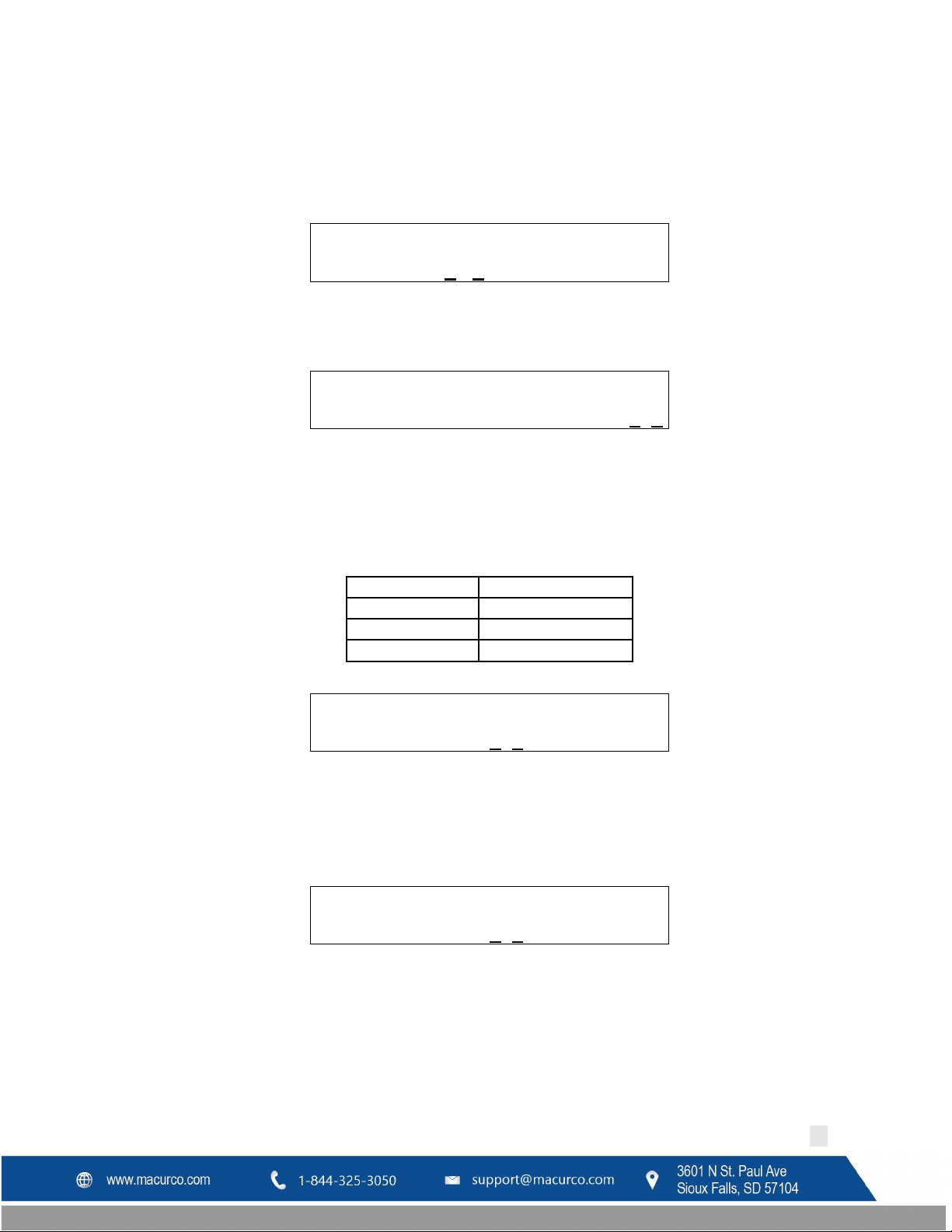
D V P - 1 2 0 C V 5. 0 1 . G
WARNING
Each time the unit is turned on it performs a self-test, which activates the audible and
contact Technical Support at 1-844-325-3050.
D V P - 1 2 0 C V 5
.0 1 .G W a r m - u p 2 : 3 0
Macurco DVP-120C Manual
4 Operations
4.1 Power up
When power is first applied to the DVP-120C, a few simple self-tests will be performed, and the system will cycle
through all status lights, and display the system model and firmware version number (Figure 4-1). The system will
then proceed to normal mode if the operating parameters have been entered.
Figure 4-1 Model Display
visual alarms. If the self-test fails, or all the alarms do not activate, do not use and
4.2 Initial Operating Mode
If the user has not entered any parameters, the system WILL NOT be controlling the ventilation system. The relays
WILL NOT actuate, and the horn and strobe outputs WILL NOT be powered. The power status light will show
NORMAL (steady green) and the system will immediately enter the CONFIGURATION mode, see section 4.2 for
details to set the configuration parameters.
If a valid set of configuration parameters have been entered, the panel will wait for all sensors to warm up. During
this time, the display will show a count-down, minutes and seconds, until the end of the warm-up period, (Figure 4-
2).
Figure 4-2 Warm-Up Display
During the warm-up period, the keypad will be locked. When the warm-up period ends, the LCD will start showing
the normal display.
4.2.1 Status Light Display
The POWER, ALARM/WARNING, SILENCE, RELAY 1, RELAY 2 and RELAY 3 status lights indicate the system status and
provide the following data:
• POWER/TROUBLE
o Green (steady) – Power is good and there are no trouble indications
o Yellow (steady) – Trouble is indicated by a transducer or the panel itself
• ALARM/WARNING
o Off – All indicated gas levels are below the warning level
o Red (steady) – One or more gas levels are at or above the alarm level
o Amber (steady) – One or more gas levels are at or above the warning level
• HUSH
REV – 1.0 [34-8708-4770-8 ] 22 | Page
Page 23

Macurco DVP-120C Manual
o Off –There are no silenced alarms or warnings
o Red (flashing) –There are alarms, warnings and/or troubles that have been silenced (gas levels may
or may not remain or continue to be at an alarm or warning levels)
• RELAY 1
o Off – Relay 1 is not on
o Green (steady) – Relay 1 is on
• RELAY 2
o Off – Relay 2 is not on
o Green (steady) – Relay 2 is on
• RELAY 3
o Off – Relay 3 is not on
o Green (steady) – Relay 3 is on
The overall system status is visible at a distance via the status lights as described above. More detailed system
information is displayed on the LCD, which can show the status of each relay and sensor. A typical status display is
shown in Figure 4-4.
4.3 User Interface
The LCD display is used to show detailed information about the status of the control system and the configuration
parameters to the user. The keypad is used to select the information displayed and to enter the configuration
parameters, which are stored in the DVP-120C memory. The keypad consists of ten-digit keys, four direction keys,
plus a MENU key that is used to access the configuration menu and a HUSH key that will silence the audible alarm
indicators. In normal mode, holding the zero key for three (3) seconds can be used to lock the keypad against
accidental (or unauthorized) use. See Section 4.5 for details.
Figure 4-3 Keypad layout
4.3.1 Cursor Keys
In normal mode, (no warnings or alarms indicated), the up and down cursor keys will scroll the display to any
configured sensors’ status. In normal mode, the left and right cursor keys will scroll through the status of each of the
relays. When the left (or right) key is used to scroll to another relay, the display will remove the underlining under
REV – 1.0 [34-8708-4770-8 ] 23 | Page
Page 24

State of the Panel
Silence Period
Alarm
5 minutes
Occupied Failure
5 minutes
Unoccupied Failure
4 hours
Warning
15 minutes
Calibration Due Warning
Refer Table 4-2
Calibration Due Trouble
15 minutes
Trouble
8 hours
Zone Signal
15 minutes
M O N 1 0 : 2 3 R 1 O F F S 0 1 C O 5 P P
M
Macurco DVP-120C Manual
the sensor number and underline the relay number; this indicates that the digit keys can be used to jump directly to
a particular relay’s status. When the up or down key is again used the display will switch back to the digit keys
jumping to a particular sensor.
4.3.2 MENU Key
The MENU key has three functions.
• First, when the system is presenting the normal display, pressing the MENU key will cause the system to
shift to the Configuration Menu.
• The second function of the MENU key is to return to the next-higher menu level, e.g. from the sensor
configuration menu to the system menu, or from the system menu out to normal mode. If in the middle of
entering a multi-digit parameter, the MENU key also cancels any changes to the parameter. When the
MENU key is used to return to normal mode, any changed configuration parameters are saved in the DVP120C’s memory.
• The third function of the MENU key is to change the LCD contrast by holding the MENU key for five (5)
seconds, at which point the LCD will prompt for further activities, see sections 4.4 for more detail.
4.3.3 Hush Key
The HUSH key is only used to silence the audible indicators (internal buzzer and possible external Horn and Strobe
devices). Pressing and releasing the button will silence the internal buzzer. The HUSH button must be held for 3
seconds to silence the Horn and Strobe devices.
The following table shows the silence period for different state of the panel.
Table 4-1 Hush function Silence Period
4.4 Normal Status Display
Figure 4-4 Normal System Display
The display shows the day of the week and the time of day, in 24-hour format. It also shows the status of one of the
relays, R1 in this example, and the type and indicated the gas concentration of one of the configured sensors, S01 is
a CO sensor indicating 5ppm in this example.
Note: The “S” will alternate between “S” (capital) and “s” (lowercase), this indicates that the sensor is
communicating with the DVP-120C
REV – 1.0 [34-8708-4770-8 ] 24 | Page
Page 25

S h o w S e n s o r _ 1
A L A R M C O S E N S O R 0 2
WARNING
Do not cover or obstruct audible alarm opening or visual alarm LED. Doing so may
adversely affect product performance.
Macurco DVP-120C Manual
Notice in Figure 4-4 that the digits 0 1 are underlined; this indicates that the digit keys can be used to jump directly
to another sensor’s status. When the first digit is pressed, the display will prompt for the second digit of the target
sensor.
Figure 4-5 Sensor Prompt
In this example, the first digit entered was 1. Since the DVP-120C can handle 99 sensors, the sensor number must be
entered in a two-digit format. For single digit number (1-9) the first digit entered would be 0 (zero). When the
second digit is entered, the normal display will be restored; showing the type and value of the selected sensor.
As mentioned above, the left and right scroll keys will display the next or previous relay’s status. The display will also
change the underline to indicate that the digit keys (zero, one and two) can be used to jump directly to a particular
relay. Since only one digit is needed to select a relay, the system does it immediately rather than prompting to show
the relay.
If the sensor is indicating a gas level that is greater than the alarm or warning levels, the gas reading will alternate
with the words ALARM or WARNING as appropriate. If a sensor fails, a connection is lost or the panel itself detects a
failure of its own, the panel will enter TROUBLE mode and the gas reading will be replaced by the word TROUBLE
(the TROUBLE status condition is discussed in section 4.7 Trouble Status Display).
4.5 ALARM Status Display
When any sensor indicates a gas level that is at or above the configured alarm level for the sensor, the panel will
enter ALARM mode, during which the internal buzzer will sound, the alarm lamp will be red and the LCD will show
the sensor type and channel number.
Figure 4-6 Alarm Display
The display will cycle through all sensors that are signaling alarm levels, at five seconds per display. Pressing any key
(except HUSH) will advance the display to the next sensor that is signaling an alarm level.
If an external horn and/or strobe are connected and configured to signal an alarm condition, they will also sound
when an alarm condition occurs, after a delay if that configuration option is used.
When the HUSH key is pressed, the internal buzzer will be silenced for five (5) minutes. If the horn or strobe turn on
delays have not finished, then they will also be silenced. If the delays have finished the HUSH key must be held for
three (3) seconds in order to silence the horn and strobe.
REV – 1.0 [34-8708-4770-8 ] 25 | Page
Page 26

A L A R M S I L E N C E D F O R 5 M I N U T E S
W A R N I N G C O S E N S O R 0 2
W A R N I N G S I L E N C E D F O R 1 5 M I N U T E S
Macurco DVP-120C Manual
When all indicators have been silenced, the display will show that alarms have been silenced for five minutes. After
any key is pressed (or five seconds), the display will return to normal mode.
Figure 4-7 Alarm Silenced message
If Relay 1 is configured as an ALARM relay, it will be turned on when an alarm condition is recognized.
4.6 Warning Status Display
When any sensor indicates a gas level that is at or above the configured warning level for the sensor, the panel will
enter WARNING mode during which the internal buzzer will sound, the alarm/warning lamp will be amber, and the
LCD will show the sensor type and channel number.
Figure 4-8 Warning display
The display will cycle through all sensors that are signaling warning levels, at five seconds per display. Pressing any
key (except HUSH) will advance the display to the next sensor that is signaling a warning level.
If the buzzer and/or an external horn and/or external strobe are connected and configured to signal a warning
condition, they will also sound when a warning condition occurs. There is a configurable delay before the horn or
strobe will sound, see sections 4.13.5 Configure Horn Submenu, 4.13.6 Configure Strobe Submenu, and
Configure Relays, Horn & Strobe.
When the HUSH key is pressed, the internal buzzer will be silenced for fifteen (15) minutes. If the horn or strobe turn
on delays have not finished, then they will also be silenced. If the delays have finished, the HUSH key must be held
for three (3) seconds in order to silence the horn and strobe.
When all indicators have been silenced, the display will show that warnings have been silenced for fifteen minutes.
After any key is pressed (or five seconds) the display will return to normal mode.
Figure 4-9 Warning Silenced message
4.13.4
4.7 Trouble Status Display
If a sensor fails, a connection is lost or the panel itself detects a failure of its own, the panel will enter TROUBLE
mode during which the internal buzzer will sound, the power lamp will be yellow, and the LCD will display the
specific sensor identified.
Possible trouble conditions are:
• Any configured channel has less than 4 mA flowing in the current loop
• A sensor is reporting a trouble condition
REV – 1.0 [34-8708-4770-8 ] 26 | Page
Page 27

T r o u b l e C O S e n s o r 0 2
T R O U B L E S I L E N C E D F O R 8 H O U R S
S e n. F a i l e d U n o c C O S e n s o r 0 2
Macurco DVP-120C Manual
• Any configured channel wiring is open or shorted.
• Internal controller board problems are detected.
Figure 4-10 Trouble display
The display will cycle through all trouble indications, at five seconds per display. Pressing any key (except HUSH) will
advance the display to the next trouble indicator.
If an external horn and/or strobe are connected and configured to signal a trouble condition, they will also sound
when a trouble condition occurs, after a delay, if that configuration option is selected.
When the HUSH key is pressed, the internal buzzer will be silenced for eight (8) hours. If the horn or strobe turn on
delays have not finished, then they will also be silenced. If the delays have finished, the HUSH key must be held for
three (3) seconds in order to silence the horn and strobe.
When all indicators have been silenced, the display will show that trouble indications have been silenced for eight
hours. After any key is pressed (or five seconds), the display will return to normal mode.
Figure 4-11 Trouble Silenced message
4.8 Unoccupied Failure Display
During unoccupied time, DVP-120C compares the readings of all CM-6 and TX-6-ND detectors connected
(irrespective of assigned zones), and if any detector is more than 15ppm (for CM-6) or 1.5ppm (for TX-6-ND) above
or below the average of all detectors (of same type) for longer than 4 hours, the detector has failed. This failure is
referred to as Unoccupied failure in rest of the manual. (Refer to “Section 4.13.2.6 Configure Occupied Time
process to define occupied time. Time outside the defined occupied time are unoccupied time.)
DVP-120C displays following message for unoccupied failure. If more than one detector fails for unoccupied time,
then display scrolls every 5 seconds period to show all failed detectors.
Figure 4-12 Unoccupied Sensor Failed
Unoccupied failure triggers alarm condition in the panel. Hence Alarm/Warning LED will be red. Buzzer, Horn and
Strobe will be energized based on Alarm Signal Configuration in configure signal menu, see section
Signals Submenu menu. Alarm due unoccupied failure have lower priority than gas alarm.
If unoccupied failure detector is part of a zone, then relays assigned to the zone gets activated.
4.13.8 Configure
” for
When the HUSH key is pressed, the internal buzzer will be silenced for 4 hours. If the horn or strobe turn on delays
have not finished, then they will also be silenced. If the delays have finished, the HUSH key must be held for three
(3) seconds in order to silence the horn and strobe.
REV – 1.0 [34-8708-4770-8 ] 27 | Page
Page 28

F a i l e d U S i l e n c e d F o r 4 h o u r s
S e n. F a i l e d O c
c. C O S e n s o r 0 2
F a i l e d O S i l e n c e d F o r 5 m i n u t e s
Macurco DVP-120C Manual
When all indicators have been silenced, the display will show that unoccupied failure indications have been silenced
for four hours. After approximately 5 seconds the display will return to normal mode.
Figure 4-13 Unoccupied Failure Silenced
In normal mode, detectors with unoccupied failure silenced will display “Failed U” alternating with current gas
reading.
4.9 Occupied Failure Display
During occupied time, system compares the readings of the CM-6 and TX-6-ND detectors assigned to a zone. If the
30 minutes rolling average for any sensor in a zone is more than 15ppm (for CM-6) or 1.5ppm (for TX-6-ND) above or
below the 30-minute rolling average for other detector(s) (of same type) in the same zone, the detector has failed.
This failure is referred to as occupied failure in rest of the manual. (Refer to “Section
Time” for process to define occupied time.)
DVP-120C displays following message for occupied failure. If more than one detector fails for occupied time, then
display scrolls every 5 seconds period to show all failed detectors.
4.13.2.5 Configure Occupied
Figure 4-14 Occupied Sensor Failure
Occupied failure triggers alarm condition in the panel. Hence Alarm/Warning LED will be red. Buzzer, Horn and
Strobe will be energized based on Alarm Signal Configuration in CONFIGURE SIGNAL menu. Alarm due occupied
failure have lower priority than gas alarm.
If occupied failure detector is part of a zone, then relays assigned to the zone gets activated.
When the HUSH key is pressed, the internal buzzer will be silenced for 5 minutes. If the horn or strobe turn on
delays have not finished, then they will also be silenced. If the delays have finished, the HUSH key must be held for
three (3) seconds in order to silence the horn and strobe.
When all indicators have been silenced, the display will show that occupied failure indications have been silenced for
5 minutes. After approximately 5 seconds the display will return to normal mode.
Figure 4-15 Occupied Failure Silenced
In normal mode, detectors with occupied failure silenced will display “Failed O” alternating with current gas reading.
4.10 Calibration Due Warning Display
When there are up to 30 days until calibration for any detectors connected, panel will trigger Calibration Due
Warning. Calibration Due Warning has lower priority than gas warning. This feature is applicable only for detector
with calibration period feature.
REV – 1.0 [34-8708-4770-8 ] 28 | Page
Page 29

C a l i b r a
t i o
n D u e C O S e n s o r 0 2
Time till Calibration
Silence Period
>14 days, and <30 days
14 days
>7 days, and <14 days
7 days
< 7 days
1 day
C a l. D u e S I L E N C E D F O R 7 d a y s
C a l i b r a
t i o
n R e q. C O S e n s o r 0 2
Macurco DVP-120C Manual
DVP-120C displays the address of the detector with calibration due warning. If there are more than one detector
with calibration due warning, then display scrolls every 5 seconds to display all detectors with calibration due
warning.
Figure 4-16 Calibration Due
During Calibration Due Warning, the warning LED will be ON. Buzzer, Horn and Strobe of the panel will be activated
based on Warning Signal Configuration in CONFIGURE SIGNAL.
When the HUSH key is pressed, the internal buzzer will be silenced. If the horn or strobe turn on delays have not
finished, then they will also be silenced. If the delays have finished, the HUSH key must be held for three (3) seconds
in order to silence the horn and strobe. Silence period is dependent on time left to calibration. Following table
shows silence period for different time to calibration.
Table 4-2 Calibration Due Silence Period
When all indicators have been silenced, the display will show that calibration due warning indication have been
silenced for corresponding silence period. After approximately 5 seconds the display will return to normal mode.
Only a calibration due warning with lower silence interval (refer Table 4-2) will reset the HUSH and panel will go back
to state indicating Calibration Due Warning.
Figure 4-17 Calibration Due Silenced
When in normal mode, for detectors with Calibration Due Warning silenced panel will display current gas reading
alternating with “Cal. Due” every second.
4.11 Calibration Overdue Trouble Display
When the panel detects a detector with Calibration Overdue condition it will go into trouble state. This trouble has
higher priority than a regular trouble condition. This feature is applicable only for detector with calibration period
feature.DVP-120C displays the address of the detector with calibration Overdue trouble. If there are more than one
detector with calibration overdue condition, then display scrolls every 5 seconds to display all detectors with this
trouble condition.
During Calibration Overdue trouble, the trouble LED will be ON. Buzzer, Horn and Strobe of the panel will be
activated based on Trouble Signal Configuration in CONFIGURE SIGNAL.
REV – 1.0 [34-8708-4770-8 ] 29 | Page
Figure 4-18 Calibration Required
Page 30

C a l. R e q S I L E N C E D F O R 1 5 M i n u t e s
Z O N E S I G N A L Z O N E 1
Macurco DVP-120C Manual
When the HUSH key is pressed, the internal buzzer will be silenced for 15 minutes. If the horn or strobe turn on
delays have not finished, then they will also be silenced. If the delays have finished, the HUSH key must be held for
three (3) seconds in order to silence the horn and strobe.
When all indicators have been silenced, the display will show that calibration due warning indication have been
silenced for 15 minutes. After approximately 5 seconds the display will return to normal mode.
Figure 4-19 Calibration Required Silenced
When in normal mode, for detectors with Calibration Overdue silenced, panel will display “Cal.Req” instead of gas
reading.
4.12 Ventilation Control
The ventilation control function operates independently from the alarm function. It provides the ability to configure
the DVP-120C for control of one to three zones. Each zone can respond to gas levels indicated by one or more of the
sensors, with configurable turn on and turn off concentrations (rising and falling) for each gas type. Each zone can
also be controlled based on the time of day.
Each zone can be configured to control one, two or all three of the relays and the external horn and strobe if
desired. When more than one zone is controlling a relay it only takes one zone to activate the relay, but all
controlling zones must release the relay before it will turn off.
Each of the relays, horn, and strobe has independent turn-on delays (to ignore short duration, transient gas signals)
and turn off delays (to ensure minimum run times for fans that must run for internal cooling).
A VFD may be enabled and controlled by the DVP-120C output relays. This allows an operator to change fixed
speeds for a VFD if it's used as a stand-alone control.
For example, an application where VFD is controlling the speed of a fan. An operator can close relay 1, 2, or 3 to set
the fan speed. If relay 1 is closed, the VFD will operate at 50%, If relay 2 is closed, the VFD will operate 75%, If relay 3
is closed, the VFD will operate at 100%.
4.12.1 Zone Signal Display
When a zone is controlling the horn or strobe and they are activated, the panel will enter ZONE SIGNAL mode during
which the horn and/or strobe will be turned on and the LCD will show the zone that is signaling.
REV – 1.0 [34-8708-4770-8 ] 30 | Page
Page 31

Z O N E S I L E N C E D F O R 1 5 M I N U T E S
5 S E N S O R S F O U N D 3 R E L A Y S F O U N D
S a v e C o n f i g . ? ( 0 = N O , 1 = Y E S )
Macurco DVP-120C Manual
Figure 4-20 Zone Signal Display
The display will cycle through all zones that are controlling the horn or strobe and are signaling, at five seconds per
display. Pressing any key (except HUSH) will advance the display to the next zone that is signaling.
When the HUSH key is held for three (3) seconds, the horn and/or strobe will be silenced for fifteen (15) minutes.
When silenced, the display will show that zone signals have been silenced for fifteen minutes. After any key is
pressed (or five seconds) the display will return to normal mode.
Figure 4-21 Zone Signal Silenced
4.13 System Configuration
The configuration menus can be entered from normal mode by pressing the MENU key. While in configuration
mode, the user can review all configuration parameters to check the current operating conditions. As an aid when
configuring the control panel, the first entry in the top menu summarizes the number of sensors and relays that the
panel is currently recognizing. Be sure that the 4-20mA output on each sensor is set to “On”.
Figure 4-22 Hardware Summary
The MENU key is also used to return to a higher-level menu and finally exit the configuration menus back to normal
mode. When exiting from the menu system to normal mode, if any configuration changes have been made, the
panel will ask whether changes are to be saved.
Figure 4-23 Save Configuration? Prompt
Pressing the zero (0) key at this point will cancel all changes except time and day of week. Pressing the one (1) will
save all changes to memory, and the changes will then become effective in controlling the ventilation system.
While the DVP-120 is in the configuration mode, alarm and ventilation control functions continue in the background
with the previously set configuration values. If an alarm condition is detected, the alarm lamp, the buzzer, the horn
and the strobe will operate as configured but the LCD will not display the detailed information. The HUSH key can be
used to silence any alarm, warning or trouble indicators without having to exit the configuration mode. If the MENU
key is used to exit the configuration mode before using the HUSH key, the LCD will display the cause of the audible
indicator.
The numeric keys are used to change the parameter displayed. The underlined character, or space, on each display,
indicates what will be changed by the digit keys.
The left and right cursor keys will enter the submenu and scroll through the items of the same type where
appropriate, e.g. enter the Configure Sensors submenu and scroll through the parameter lists for the existing
sensors.
REV – 1.0 [34-8708-4770-8 ] 31 | Page
Page 32

T i m e : 2 2 : 5 5 D a y : T u e s d a y
T i m e : 0 1 : 5 5
Macurco DVP-120C Manual
The up cursor key scrolls through the menu entries in the order listed here, while the down cursor key scrolls in the
reverse order.
Changing the configuration parameters requires the entry of a password before changes can be made. The default
password is 1234. See Figure 4-46 Enter Password
In many cases, the parameter is entered as a string of digits, but some parameters are selected by pressing a single
key, e.g. pressing 1 selects Monday, 2 selects Tuesday, etc.
for an example of the password prompt.
4.13.1 System Menu
The top menu level allows the user to select:
• Configure System
• Configure Sensors
• Configure Relays, Horn & Strobe
• Configure Zones
• Configure Signals
The up and down cursor keys can be used to scroll through the entries in the list, while the left or right key will enter
the submenu.
The MENU key will return to normal mode. If any configuration parameters have been changed, the panel will
prompt to save the changes. If the changes are saved, this is the point at which they become effective in controlling
the ventilation system and for alarm level detection. Note that changes to the time and day of week are not
considered configuration items; they are saved as soon as they are entered.
4.13.2 Configure System Submenu
The system configuration submenu provides entries to:
• Set the time of day, 24-hour format
• Set the day of the week, day 1 is Monday
• Load Default Configuration
• Change Password
• Configure Sensor Type
• Configure Modbus
• Configure Occupied Periods
4.13.2.1 Set Time of Day
Figure 4-24 Set Time of Day
This display example shows that the time is 22:55 (10:55 PM). The underlined characters indicate that the numeric
keys can be used to set the current time of day. When the first digit is entered (and after the password is entered if
required), the display will change to show that the “hour” portion of the time is currently being entered.
REV – 1.0 [34-8708-4770-8 ] 32 | Page
Page 33

D a y : T u e s d a y
T i m e : 1 6 : 5 5 D a y : T u e s d a y
T i m e : 2 2 : 5 5 D a y : 2 T u e s d
a y
1 L o a d D e f a
u l t C o n f i g u r a t i o n
Macurco DVP-120C Manual
Figure 4-25 Enter Hours
In this example, the first digit entered was 1 (one), and the panel is waiting for the second digit of the hour to be
entered. If the second digit is not entered within five seconds, the time will revert to the previous value. After the
second digit of the hour is entered, the display will prompt for the “minute” entry
Figure 4-26 Enter Minutes
In this example, the hour (16) has been accepted and the panel is waiting for the minute to be entered. If no digits
are entered within 5 seconds, the entry will be finished without changing the minute; however, the hour will be
changed to the value entered.
Note that the time is saved as soon as the fourth digit is entered.
4.13.2.2 Set Day of Week
Figure 4-27 Set Day of the Week
This display example shows that Tuesday is the current day of the week. The underline character indicates that the
day can be changed by entering the corresponding digit:
• 1 Monday
• 2 Tuesday
• 3 Wednesday
• 4 Thursday
• 5 Friday
• 6 Saturday
• 7 Sunday
Note that the day of the week is saved as soon as the digit is entered.
4.13.2.3 Load Default Configuration
Figure 4-28 Load Default Configuration
When the number one (1) digit is pressed, the panel will prompt for the password, even if it has been entered
previously. If the password is entered correctly, the panel will overwrite the existing configuration with the default
configuration. This operation is intended to restore the panel to a known basic condition if it is removed from one
installation and installed in another.
Default Configuration
1 Password 1234
REV – 1.0 [34-8708-4770-8 ] 33 | Page
Page 34

Type
CO
NO2
Range
200ppm
20ppm
Alarm Level
200ppm
5ppm
Warning
Level
Rising Level
35ppm
2.5ppm
Falling Level
15ppm
1.2ppm
C h a n g e P a s s w o r d * * * *
B a u d R a t e: 0 - 1 9 2 0 0 B d
Macurco DVP-120C Manual
2 Sensors Undefined
3 Alarm signals Buzzer = Intermittent, Horn = Intermittent, Strobe = Continuous
4 Warning signals Buzzer = Off, Horn = Off, Strobe = Off
5 Trouble signals Buzzer = Triple Tap, Horn = Off, Strobe = Off
6 Relay 1 Normally off, 1-minute turn on delay, 1 minute minimum on time
7 Relay 2 Normally off, 1-minute turn on delay, 1 minute minimum on time
8 Relay 3 Normally off, 1-minute turn on delay, 1 minute minimum on time
9 Horn Normally off, 1-minute turn on delay, 0 (zero) minimum on time
10 Strobe Normally off, 1-minute turn on delay, 0 (zero) minimum on time
11 Zone 1 Controls R1
12 Zone 2 Controls R2
13 Zone 3 Controls R3
14 Group 1 in each zone Type 1 CO, Voting mode, Quorum = 1
15 Group 2 in each zone Type 2 NO2, Voting mode, Quorum = 1
Description
Table 4-3 Default Configuration Settings
4.13.2.4 Change Password
Figure 4-29 Change Password
When the first digit is entered to change the password, the panel will prompt for the existing password to be
entered (if it hasn’t already been entered), see section 4.13.2.8 Enter Password
password has been entered, the panel will prompt for the new password.
4.13.2.5 Configure Modbus
Carbon
Monoxide
100ppm 3ppm
Nitrogen
Dioxide
for more detail. Once the current
REV – 1.0 [34-8708-4770-8 ] 34 | Page
Page 35
I
n
t e r
-- f r a m e a d d d e l a
y: 0 1 m s e c
R e a d i n g R e t r i e s : 1
2
Baud Rate
Reading Retries
19200 (Default)
12 (Default)
9600
8
4800
5
C a n D
i s c o v e r : 9 9 E n a b l e d : 9 9
F o u n d 0 6 o f 9 9 E
n a b l e d : 9 9
Macurco DVP-120C Manual
Figure 4-30
You can change the baud rate for communication with detector with this menu. Default baud rate is 19200. The
underlined character indicate that the numeric keys can be used to change the baud rate. Valid entries are 0, 1 and 2
corresponding to baud rate of 19200, 9600 and 4800 respectively.
Figure 4-31
This is a delay added between frame for communication between detectors and panel. It is recommended to leave
this to the default value of 01 msec.
Figure 4-32
This parameter is number of times panel will attempt to receive readings from panel before going into trouble state.
The underlined characters indicate that the numeric keys can be used to change the value.
NOTE: Change the value of Reading Retries according to table below, every time the baud rate for the panel is
changed.
Table 4-4
Figure 4-33
This menu option is useful for troubleshooting. Normally all sensors register automatically. This shows how many
detectors the panel can discover and how many of them are enabled. You can enable or disable any specific
detector address entering this menu. If any of the detector address is disabled, then the panel will not attempt
communication with the corresponding detector.
Figure 4-33
This menu shows how many detectors have been registered. In this example, the display example shows that panel
has discovered 6 detectors out of maximum possibility of 99. This means 93 more detectors can be connected to the
panel.
REV – 1.0 [34-8708-4770-8 ] 35 | Page
Page 36
W e e k d a y n u m b e r a c t i v e p e r i o d: 0
W e e k e n d n u m b e r a c t i v e p e r i o d: 0
W e e k e n d p e r i o
d: 1 0 7: 0 0 t o 0 7: 0 0 W e e k d a y p e r i o
d: 1 0 7: 0 0 t o 0 8: 0 0
Macurco DVP-120C Manual
4.13.2.6 Configure Occupied Time
DVP-120C monitors the readings of Macurco CM-6 detectors connected to the panel and compares the readings of
detectors to detect occupied failure and unoccupied failure. Refer to Section 4.8 Unoccupied Failure Display and
Occupied Failure Display for details on these failures.
“Configure Occupied Period” is used to define occupied time for DVP-120C. Up to 2 occupied period can be defined
for each week day and weekend. Any time period outside defined occupied time period is unoccupied time period.
By default, all times are unoccupied times.
Press Left or Right key to enter the “Configure Occupied Period” menu and use UP or DOWN key to scroll through
sub-menu of Configure Occupied Time menu. Before one can make any changes to these settings panel will prompt
to enter the current password.
Weekday/Weekend Number Active Period
In this sub-menu of Configure Occupied Time, you can define how many occupied periods you want to define for
weekday and weekend. Valid entries are 0,1 and 2. Default value of 0 corresponds to disabled occupied period.
4.9
Figure 4-34 Active Period Weekday
Press LEFT key to go back to previous menu i.e. ‘Configure Occupied Time’. Press RIGHT key to enter this
configuration menu and access Weekday/Weekend Period sub-menu.
Weekday/Weekend Period
This configuration menu is available only if active period for weekday or weekend is 1 or 2.
Figure 4-35 Active Period Weekend
Default Weekdays occupied times are 07:00 to 08:00 (Period 1) and 15:00 to 16:00 (Period 2). Default Weekends
occupied times are 07:00 to 07:00 (Period 1) and 15:00 to 15:00 (Period 2).
If active period entered was 2, press UP or DOWN key to scroll between Period 1 and Period 2. Press LEFT key to
return to previous menu. Press RIGHT key to enter this configuration and enter Start and End time for corresponding
period.
REV – 1.0 [34-8708-4770-8 ] 36 | Page
Page 37

W e e k d a y p e r i o
d: 1 S t a r t T i m e: 0 7: 0 0 W e e k d a y p e r i o
d: 1 E n d T i m e: 0 8: 0 0
Config.
changed
Any
Key
to
save
Configure
sensor
Macurco DVP-120C Manual
Start/End Time
At this point, you will define start and end time for occupied period during weekend or weekday. Values entered for
Start and End time are in 24-hour format. If value entered for Weekday/Weekend active period is 2, you need to
enter Start Time and End Time for 2 periods separately. Notice the following figure specify on the first line that Start
Time and End Time corresponds to Week Day Period 1. This means time period of 7 AM to 8AM is regarded as
occupied time for DVP-120C during weekdays.
Figure 4-36 Occupied Time Period
Press UP and DOWN key to scroll between Start Time and End Time. To enter the time, scroll to corresponding
screen i.e. Start Time or End Time, and start entering value via keypad. First two entered digits are hours and next
two pressed digits are minutes. To enter single digit hour, enter 0 as first digits. E.g. for 8:30 AM, enter 08 and then
30.
Press LEFT key to go back to previous menu.
4.13.2.7 Configure sensor Type
Sensor Registration
Sensor registration is continuously monitored by the DVP-120. When the currently selected sensor type agrees with
the stored registration information the DVP-120 will remain in normal mode. When new registration information is
detected by the DVP-120, for example, if a different gas type of Macurco sensor was installed, the following
message is displayed: “Configuration Changed Any key to save” is displayed.
Figure 4-37 Configuration Changed
Pressing any key will prompt the user to enter the password. Once the valid password is entered the new sensor
type is saved. The program does not allow any other activity unless a valid password is entered.
If the DVP-120 is in configuration mode (user is changing the configuration) the registration information is saved in
the background and the message indicating that configuration was changed is delayed until the user goes back to
normal mode.
Customer Sensor Implementation
NOTE: Although these options are viewable on the panel, the menu is read only. The DVP-120C does not support the
addition of wildcard sensors.
REV – 1.0 [34-8708-4770-8 ] 37 | Page
Page 38

type
Type: 01
CO
Good definition
Type:
01
Tag:
CO
♦
Type: 01
CO
Units:
ppm
♦
Type: 01
CO
Depletion:
0 No
Type: 01
CO
Dec.: 0
8888.
ppm
Type: 01
CO
Res.:
1 ppm
Macurco DVP-120C Manual
Figure 4-38 Configure Sensor Type
From this menu, you can access any of the following menus to view type parameters using the navigation key up,
down, left and right. This menu is read only i.e. changes cannot be made.
Figure 4-39 Sensor Definition
CO for carbon monoxide is one of the 2 Macurco sensor types already defined
Figure 4-40 Sensor Tag
“Tag” is a 3-character parameter and is used to identify the sensor type (i.e. CO, NO
Figure 4-41 Sensor Units
“Units” is a 4-character parameter and indicates the engineering units (i.e. ppm)
Figure 4-42 Depletion Type
“Depletion” is “1” when the sensor is a depletion type and “0” when it is not a depletion type sensor. A depletion
sensor detects when gas concentrations in a space fall below a specified level.
2
...)
“Dec.” defines how many decimal points are used to display the reading, alarm, warning, range, rising and falling
levels. It can have values between 0 and 2.
REV – 1.0 [34-8708-4770-8 ] 38 | Page
Figure 4-43 Decimal Points
Page 39

Type: 01
CO
Range:
200
ppm
Type: 01
CO
Alarm:
200
ppm
Type: 01
CO
Warn:
100
ppm
Type: 01
CO
Rise:
35
ppm
Type: 01
CO
Fall:
15
ppm
E n t e r P a s s w o r d _ _ _ _
E n t e r P a s s w o r d _ _ _ *
Macurco DVP-120C Manual
Figure 4-44 Resolution
“Res.” Defines the resolution used to display the reading, alarm, warning, range, falling level and rising level. It can
have values between 1 and 500 when “Dec.” is 0, 50.0 when “Dec.” is 1 and 5.00 when “Dec.” is 2.
Figure 4-45 Sensor Range
“Range” is the value displayed when current measured is 20mA.
Figure 4-46 Alarm Level
“Alarm” is the default alarm range.
Figure 4-47 Warning Level
“Warn” is the default warning range.
Figure 4-48 Rising Trip Point
“Rise” is the default rising level used in Zone configuration.
Figure 4-49 Falling Trip Point
“Fall” is the default falling level used in Zone configuration.
4.13.2.8 Enter Password
If the password has not yet been entered, when the first digit of any parameter is entered, the panel will prompt for
the current password. Note that the first digit entered is discarded; it does not count toward the password or
toward the parameter entry.
When the first digit is entered, the panel will show
REV – 1.0 [34-8708-4770-8 ] 39 | Page
Figure 4-50 Enter Password
Page 40

W r o n g P a s s w o r d
WARNING
Use only for monitoring the gases which the sensors and equipment are designed to
serious injury or death. For proper use, see supervisor or User manual, or Contact
Technical Support at 1-844-325-3050.
S e n s o r 0 1 C O A : 2 0 0 W : 5 0
S e n s o r 0 1 C O T y p e : 1
Macurco DVP-120C Manual
Figure 4-51 Password Prompt
If the password is not entered correctly the panel will display
Figure 4-52 Wrong Password Prompt
Once the current password has been entered, the panel will prompt for the configuration parameter being changed.
If the password has been lost:
• Power down the DVP-120C.
• Remove the Jumper Shorting Connector from the EXT header and place the Jumper Shorting Connector onto
the top two pins of the SYS header.
• Power up the DVP-120C. The first display is the current password on the unit.
• Remove the Jumper Shorting Connector from the SYS header and install back onto the two bottom pins of
the EXT header.
detect. Failure to do so may result in exposures to gases not detectable and result in
4.13.3 Configure Sensors Submenu
There is a list of parameters for each sensor in the system, either currently wired or configured but presently
disconnected. The left and right cursor keys can be used to move from one sensor to another and the up and down
keys will scroll through the parameters for the particular sensor.
4.13.3.1 Sensor Summary
Figure 4-53 Sensor Summary
This display example shows that the sensor on channel 01 has been configured as a Carbon Monoxide sensor with
an Alarm level of 200ppm and a Warning level of 50ppm.
Notice that the sensor number, 01 in this example, is underlined. This indicates that the digit keys can be used to
jump to a particular channel, even if there is no sensor connected to the channel.
4.13.3.2 Sensor Type
REV – 1.0 [34-8708-4770-8 ] 40 | Page
Page 41

S e n s o r 0 1 C O A l a r m : 2 0 0 p p
m
Carbon
Monoxide
Nitrogen
Dioxide
Alarm
Level
S e n s o r 0 1 C O W a r n i n g : _ 5 0 p p
m
Carbon
Monoxide
Nitrogen
Dioxide
Warning
Level
S e n s o r 0 1 C O R a n g e : 2 0 0 p p
m
Macurco DVP-120C Manual
Figure 4-54 Sensor Summary
This display example shows that the sensor on channel 01 has been configured as a Carbon Monoxide Sensor. The
valid entries for Macurco type sensors are Carbon Monoxide (CO), and Nitrogen Dioxide (NO
Setting the sensor type to 0 (zero) will cause the display to ask if the user wants to DELETE the sensor. If the answer
is yes, the configuration record for this sensor channel will be deleted and the channel will no longer be used to
control the ventilation system. When a sensor’s type is changed, the alarm level, warning level, and range will be set
to the default for the sensor type.
The following three parameters are not accessible until a sensor type of 1, or 2 is selected.
4.13.3.3 Alarm Set Point
Figure 4-55 Sensor Alarm Level
The default alarm levels for the sensors are:
Description
).
2
200ppm 5ppm
Table 4-5 Default Alarm levels
Setting an alarm level of 0 (zero) will disable alarm detection for this sensor.
4.13.3.4 Warning Set Point
Figure 4-56 Sensor Warning Level
The default warning levels for the sensors are:
Description
100 ppm 3 ppm
Table 4-6 Default warning levels
Setting a warning level of 0 (zero) will disable warning detection for this particular sensor.
4.13.3.5 Range
Figure 4-57 Sensor Range
The range for each sensor is the gas concentration that corresponds to the 20-mA signal level.
REV – 1.0 [34-8708-4770-8 ] 41 | Page
Page 42
Carbon
Monoxide
Nitrogen
Dioxide
Rang
200 ppm
20 ppm
R e l a y 1 N o r m . O f f D e l a y O n , M i n . O n
R e l a y 1 N o r m . O f f M o d e : 2
R e l a y 1 D e l a y O n ( m m : s s ) 0 1 : 0 0
Macurco DVP-120C Manual
The default range values for the sensor are:
Description
Table 4-7 Default Range
4.13.4 Configure Relays, Horn & Strobe Submenu
There is a list of parameters for each relay in the system. The left and right cursor keys can be used to move from
one relay, horn or strobe to another and the up and down keys will scroll through the parameters for the particular
relay, horn or strobe.
4.13.4.1 Relay Summary
Figure 4-58 Relay Summary
This display example shows that Relay 1 is configured to operate Normally Off, with a turn-on delay and a minimum
on time.
Notice that the relay number, 1 in this example, is underlined. This indicates that the digit keys can be used to jump
to a particular relay, horn or strobe. The relays are numbers 1, 2 and 3; the horn is number 4 and the strobe is 5.
4.13.4.2 Relay Mode
Figure 4-59 Relay Mode
This display example shows that relay 1 is configured to operate in the Normally Off mode. The relay modes are:
• 1 ALARM
• 2 Normally Off (default)
• 3 Normally On
Relay mode 1 is a special case. This mode is only available on relay 1 and dedicates the relay to function as an alarm
signal to a subsequent alarm or monitoring panel. This mode forces the relay to Normally Off mode with no turn on
delay or minimum on time. See Section 4.5 ALARM Status Display
Fail Safe operation can be implemented by configuring a relay to operate Normally On, and wiring the circuit using
the NC (normally closed) contact. In this way, if the control panel loses power the relay will turn on the controlled
device if it still has power.
4.13.4.3 Relay Turn on Delay
for more detail regarding alarms.
REV – 1.0 [34-8708-4770-8 ] 42 | Page
Page 43

R e l a y 1 M i n . O n ( m m : s s ) 0 1 : 0 0
H o r n 4 D e l a y O n
H o r n D
e l a y O n ( m m : s s ) 0 1 : 0 0
H o r n M i n . O n ( m m : s s ) 0 0 : 0 0
S t r o b e 5
Macurco DVP-120C Manual
Figure 4-60 Delay time
The default turn-on delay is one minute, and the maximum allowed value is fifteen minutes. The value is entered in
two groups, 2 digits for the minutes and then 2 digits for the seconds. A leading zero must be entered for each group
if applicable.
4.13.4.4 Relay Minimum on Time
Figure 4-61 Minimum on time
The default minimum on time is one minute and the maximum allowed value is fifteen minutes.
4.13.5 Configure Horn Submenu
The configuration parameters for the horn are similar to those for relays. A horn would not normally require a
minimum on time, but this parameter allows a more versatile configuration.
4.13.5.1 Horn Summary
Figure 4-62 Horn Summary
This display example shows that the horn has been configured to operate with a turn on delay and no minimum on
time.
Notice that the horn number, 4, is underlined. This indicates that the digit keys can be used to jump to a particular
relay, horn or strobe. The relays are numbers 1, 2 and 3; the horn is number 4 and the strobe is 5.
4.13.5.2 Horn Turn on Delay
Figure 4-63 Horn Turn on Delay
The default turn-on delay is one minute, and the maximum allowed value is fifteen minutes.
4.13.5.3 Horn Minimum on Time
Figure 4-64 Horn Minimum on Time
The default minimum on time is zero and the maximum allowed value is fifteen minutes.
4.13.6 Configure Strobe Submenu
The configuration parameters for the strobe are the same as those for relays. A strobe would not normally require a
minimum on time, but this parameter allows a more versatile configuration.
4.13.6.1 Strobe Summary
REV – 1.0 [34-8708-4770-8 ] 43 | Page
Page 44

D e l a y O n
S t r o b e D e l a y O n ( m m : s s ) 0 1 : 0 0
S t r o b e M i n . O n ( m m : s s ) 0 0 : 0 0
Z o n e 1 C o n t r o l s R 1 R 2 R 3 H 4 S 5
Macurco DVP-120C Manual
Figure 4-65 Strobe Summary
This display example shows that the strobe has been configured to operate with a turn on delay and no minimum on
time.
Notice that the strobe number, 5, is underlined. This indicates that the digit keys can be used to jump to a particular
relay, horn or strobe. The relays are numbers 1, 2 and 3; the horn is number 4 and the strobe is 5.
4.13.6.2 Strobe Turn on Delay
Figure 4-66 Strobe Turn on Delay
The default turn-on delay is one minute, and the maximum allowed value is fifteen minutes.
4.13.6.3 Strobe
Figure 4-67 Strobe Minimum on Time
The default minimum on time is zero and the maximum allowed value is fifteen minutes.
4.13.7 Configure Zones Submenu
The DVP-120C ventilation control can support up to three zones. The zone functionality makes the DVP-120C very
flexible. For example, each zone can be configured to monitor a separate set of four sensors and control a single
relay.
Another control scheme uses one zone to monitor all sensors and turn one relay on at a relatively low gas
concentration. A second zone monitors the same sensors and turns on a second relay if the gas concentration
reaches a higher level. The third zone can also monitor the same relays turning the last relay on as a signaling device
to a live monitor station, as well as turning on the external horn and strobe, under the assumption that the
ventilation system is not working.
In addition to controlling the relays based on the gas concentration, each zone can have a timed function, e.g. turn
on low volume ventilation fans at 7:00 AM and turn them off at 8:00 PM.
The default Ventilation Controls are:
• Zone 1 controls Relay 1
• Zone 2 controls Relay 2
• Zone 3 controls Relay 3
4.13.7.1 Zone Controls
REV – 1.0 [34-8708-4770-8 ] 44 | Page
Page 45

Z 1 G r o u p 1 N O 2 S e n s o r T y P e : 2
Macurco DVP-120C Manual
Figure 4-68 Zone Controls
This display example shows that Zone 1 is configured to control all of the relays plus the horn and the strobe. Each of
the relays, the horn, and the strobe can be removed from (or added to) the zones control by pressing the indicated
digit key. By default, Zone 1 will control Relay 1, Zone 2 will control Relay 2 and Zone 3 will control Relay 3.
Definitions:
• Zone – Defines Sensor Input & Relay / Alarm Output
• Group – Set of Sensors of the same type and output within the same zone
• Average – Activation based upon an average of sensors in a group
• Voting – Number of sensors needed to be above trip point to activate the output
• Quorum – Number of sensors need to vote, 1 = any sensor
The digit controls are:
• 1 Relay 1 added/removed from the zone’s control
• 2 Relay 2 added/removed from the zone’s control
• 3 Relay 3 added/removed from the zone’s control
• 4 Horn added/removed from the zone’s control
• 5 Strobe added/removed from the zone’s control
When controlled by a zone the default horn pattern is the Triple Tap pattern, see section
Submenu, and the strobe will turn on continuously when a zone is controlling them.
Each zone can have up to three control groups defined. Each group either monitors a sensor type or implements a
timer function.
4.13.7.2 Zone Group Type
Figure 4-69 Zone Group Type
This display example shows that group 1 in zone 1 will be monitoring Nitrogen Dioxide sensors. The valid Types are:
• 0 Timed
• 1 Carbon Monoxide (CO)
• 2 Nitrogen Dioxide (NO
The default Types are:
• Group 1 in each zone Type 1 CO, Voting mode, Quorum = 1
• Group 2 in each zone Type 2 NO2, Voting mode, Quorum = 1
Timed mode turns the zone’s outputs on at the START TIME if the current day is a weekday (or a weekend) and turns
them off at the next occurrence of STOP TIME. The other three modes turn the outputs on if the gas concentration
indicated by that type of sensor is at or above the Rising Trip Point and turns the outputs off if the concentration is
less than or equal to the Falling Trip Point.
)
2
4.13.6 Configure Strobe
REV – 1.0 [34-8708-4770-8 ] 45 | Page
Page 46

Z 1 G r o u p 1 T i m e d D a y s : 1 W e e k d a y
s
Z 1 G r o u p 1 T i m e d S t a r t T i m E : 0 7 : 0
0
Z 1 G r o u p 1 T i m e d S t o p T i m e : 1 8 : 0
0
Z 1 G r o u p 1 N O 2 S e n s o r s : 0 2 , 0 4 , 1
1
Z 1 G r o u p 1 N O 2 A d d / R e m o v e : _ 0
Z 1 G r o u p 1 N O 2 R i s i n g : 2 . 5 p p
m
Macurco DVP-120C Manual
4.13.7.3 Timed Day Selection
Figure 4-70 Timed Day Selection
Valid entries are:
• 1 Weekdays, Monday thru Friday, (default)
• 2 Weekends, Saturday and Sunday
4.13.7.4 Start Time
Figure 4-71 Start Time Selection
The start time is entered in 24-hour format and the default value is 07:00 (7:00 AM).
4.13.7.5 Stop Time
Figure 4-72 Stop Time Selection
The stop time is entered in 24-hour format and the default value is 18:00 (6:00 PM).
4.13.7.6 Sensor Selection
Figure 4-73 Sensor Selection
Sensors are included or removed from the group by entering the two-digit channel number. After a sensor is added
or removed, the list will be re-sorted so it does not matter in which order the sensors are added or removed. The
default is to include all sensors of the specified type.
When the first digit of a sensor number is entered (a leading zero must be entered if the number is less than ten),
the display will prompt to Add or Remove a sensor from the group.
Figure 4-74 Add / Remove sensor prompt
When the second digit is entered, the sensor will be added or removed from the control group, provided the sensor
is of the proper type, NO
entered, the request will not be completed.
in this example. If the sensor is of the wrong type, or an invalid sensor channel number is
2
4.13.7.7 Rising Trip Point
REV – 1.0 [34-8708-4770-8 ] 46 | Page
Page 47

Carbon
Monoxide
Nitrogen
Dioxide
Type
CO
NO
2
Rising
Level
Z 1 G r o u p 1 N O 2 F a l l i n g : 1 . 0 p p
m
Carbon
Monoxide
Nitrogen
Dioxide
Type
CO
NO
2
Falling
Level
Z 1 G r o u p 1 N O 2 M o d e : 2 V o t i n g
Macurco DVP-120C Manual
The default rising trip points are:
4.13.7.8 Falling Trip Point
The default falling trip points are:
Figure 4-75 Rising Trip Point Entry
Description
35 ppm 2.5 ppm
Table 4-8 Default Rising Trip Point
Figure 4-76 Falling Trip Point Entry
Description
15 ppm 1.2ppm
Table 4-9 Default Falling trip point
4.13.7.9 Multiple Sensor Mode
Figure 4-77 Sensor Mode Selection
When multiple sensors are being monitored by a group, the output decision can be based on either voting, as shown
here, or the average of all sensors in the group. Valid modes are:
• 1 Average
• 2 Voting (default)
When the configuration is Average, the gas concentrations from all sensors in the group are averaged and if the
average is greater than or equal to the rising trip point the zone outputs(s) are activated. When the average is less
than or equal to the falling trip point the zone output(s) is de-activated. If the average is between the two trip
points, the outputs remain in their previous state.
When the configuration is Voting, the number of sensors in the group indicating a value greater than or equal to the
rising trip point is counted. If the count is greater than or equal to the quorum then the zone output(s) are activated.
If the count of sensors indicating less than or equal to the falling trip point is greater than or equal to the quorum
the zone output(s) is de-activated. Activating the output(s) is given priority if a group has an equal number of
sensors with gas readings greater than or equal to the rising trip point and sensors with readings less than or equal
to the falling trip point.
4.13.7.10 Multiple Sensor Quorum
REV – 1.0 [34-8708-4770-8 ] 47 | Page
Page 48

Z 1 G r o u p 1 N O 2 Q u o r u m : _ 2
A l a r m S i g n a l s B u z z , H o r n , S t r o b
E
A l a r m S i g n a l s B u z z : 2 I n t e r m i t
.
A l a r m S i g n a l s H o r n : 2 I n t e r m i t
.
Macurco DVP-120C Manual
Figure 4-78 Quorum Entry
It is up to the installer to ensure that the quorum entry is appropriate for the configuration. Valid entries are one to
twelve, but a value greater than the number of sensors being monitored by the group stops the group from
controlling the outputs. The default quorum value is 1.
4.13.8 Configure Signals Submenu
The DVP-120C can drive the buzzer, horn, and strobe with different sound patterns to indicate the severity of the
current conditions. These patterns are selectable by the installer using this group of submenus. Once again, the left
and right keys will scroll through the signal types and the up and down keys will scroll to the signal sources.
4.13.8.1 Alarm Signal Summary
The alarm signals are in response to one or more sensors indicating gas levels at or above the sensors’ configured
alarm level.
Figure 4-79 Alarm Signals
This display example shows that alarms are signaled by the internal buzzer, the external horn, and the strobe.
4.13.8.2 Alarm Buzzer Signal
Figure 4-80 Buzzer Alarm Signal
This display example shows that the buzzer will signal an alarm condition with an intermittent signal. The signal
definitions are:
• 1 Continuous Buzzer sound continuously
• 2 Intermittent One second on at two-second intervals (default)
• 3 Double tap Two beeps at five-second intervals
• 4 Triple tap Three short beeps at ten-second intervals
• 5 Off Buzzer will not sound
4.13.8.3 Alarm Horn Signal
Figure 4-81 Horn Alarm Signal
This display example shows that the horn will signal an alarm condition with an intermittent signal. The signal
definitions are:
• 1 Continuous Horn sounds continuous (default)
• 2 Intermittent One second on at two-second intervals
REV – 1.0 [34-8708-4770-8 ] 48 | Page
Page 49

A l a r m S i g n a l s S t r o b e : 1 C o n t i n
.
W a r n i n g S i g n a l s B u z z
W a r n i n g S i g n a l s B u z z : 5 O F
F
W a r n i n g S i g n a l s
Macurco DVP-120C Manual
• 3 Double tap Two beeps at five-second intervals
• 4 Triple tap Three short beeps at ten-second intervals
• 5 Off Horn will not sound
4.13.8.4 Alarm Strobe Signal
Figure 4-82 Alarm Signals
This display example shows that the strobe will signal an alarm condition with a continuous signal. The signal
definitions are:
• 1 Continuous (default)
• 2 Intermittent One second on at two-second intervals
• 3 Double tap Two beeps at five-second intervals
• 4 Triple tap Three short beeps at ten-second intervals
• 5 Off Strobe will not flash
4.13.8.5 Warning Signal Summary
The warning signals are in response to one or more sensors indicating gas levels at or above the sensors’ configured
warning level.
Figure 4-83 Warning Signal
This display example shows that warnings are signaled by the internal Buzzer only.
4.13.8.6 Warning Buzzer Signal
Figure 4-84 Buzzer Warning Signal
This display example shows that the buzzer will not signal a warning condition. The signal definitions are:
• 1 Continuous
• 2 Intermittent One second on at two-second intervals
• 3 Double tap Two beeps at five-second intervals
• 4 Triple tap Three short beeps at ten-second intervals
• 5 Off Buzzer will not sound (default)
4.13.8.7 Warning Horn Signal
REV – 1.0 [34-8708-4770-8 ] 49 | Page
Page 50

H o r n : 5 O F
F
W a r n i n g S i g n a l s S t r o b e : 5 O F
F
T r o u b l e S i g n a l s B u z z
T r o u b l e S i g n a l s B u z z : 4 T r i p l
e
Macurco DVP-120C Manual
Figure 4-84 Strobe Warning Signal
This display example shows that the horn will not signal a warning condition. The signal definitions are:
• 1 Continuous
• 2 Intermittent One second on at two-second intervals
• 3 Double tap Two beeps at five-second intervals
• 4 Triple tap Three short beeps at ten-second intervals
• 5 Off Horn will not sound (default)
4.13.8.8 Warning Strobe Signal
Figure 4-85 Strobe Warning Signal
This display example shows that the strobe will not signal a warning condition. The signal definitions are:
• 1 Continuous
• 2 Intermittent One second on at two-second intervals
• 3 Double tap Two beeps at five-second intervals
• 4 Triple tap Three short beeps at ten-second intervals
• 5 Off Strobe will not flash (default)
4.13.8.9 Trouble Signal Summary
The trouble signals are in response to one or more sensor faults, either as a defined current level or because of
wiring problems.
Figure 4-86 Trouble Signals
This display example shows that troubles are signaled by the internal buzzer only.
4.13.8.10 Trouble Buzzer Signal
Figure 4-87 Buzzer Trouble Signal
This display example shows that the buzzer will signal a trouble condition with a triple tap signal. The buzzer signal
definitions are:
• 1 Continuous
• 2 Intermittent One second on at two-second intervals
REV – 1.0 [34-8708-4770-8 ] 50 | Page
Page 51

T r o u b l e S i g n a l s H o r n : 5 O F
F
T r o u b l e S i g n a l s S t r o b e : 5 O F
F
Macurco DVP-120C Manual
• 3 Double tap Two beeps at five-second intervals
• 4 Triple tap Three short beeps at ten-second intervals (default)
• 5 Off Buzzer will not sound
4.13.8.11 Trouble Horn Signal
Figure 4-88 Horn Trouble Signal
This display example shows that the horn will not signal a trouble condition. The horn signal definitions are:
• 1 Continuous
• 2 Intermittent One second on at two-second intervals
• 3 Double tap Two beeps at five-second intervals
• 4 Triple tap Three short beeps at ten-second intervals
• 5 Off Horn will not sound (default)
4.13.8.12 Trouble Strobe Signal
Figure 4-89 Strobe Trouble Signal
This display example shows that the strobe will not signal a trouble condition. The strobe signal definitions are:
• 1 Continuous
• 2 Intermittent One second on at two-second intervals
• 3 Double tap Two beeps at five-second intervals
• 4 Triple tap Three short beeps at ten-second intervals
• 5 Off Strobe will not flash (default)
REV – 1.0 [34-8708-4770-8 ] 51 | Page
Page 52

Macurco DVP-120C Manual
5 BACnet
5.1 General Information
Following standard objects defined by BACnet are used in DVP-120C:
a. Analog Input
b. Binary Input
BACnet objects available for each detector connected to DVP-120C are as follows:
5.1.1 Analog input – Sensor ID
The value in the BACnet object refers to the Sensor ID/Type of Macurco Gas detector. Values of 1 to 8 are only valid
values.
5.1.2 Analog Input – Gas Reading
This represents the gas reading of the detector. If the reading is not reliable then it will have value 6553.5. The
reading may be unreliable for any of the following reasons:
• Registration Status of MRS-485 is non-zero (it is non-zero during detector warm-up period, trouble code,
MRS-485 registration in progress, and other miscellaneous MRS-485 error indicated by red Status LED in
MRS-485).
• A successful request/response has not been detected for the reading (i.e. a timeout occurred, or a
detector does not exist).
• The reading is under or over range DVP-120C compares the current reading of a detector with its range
and anytime it is outside the range, it will set the gas reading to 6553.5.
• Invalid Sensor ID Type (1 - 9 are the only valid values).
5.1.3 Binary Input – MRS Trouble
This binary input object is set (i.e. the value is 1) when there is an error in MRS-485.
5.1.4 Binary Input – Over Range
This binary input object is set when reading from the detector is over the range.
5.1.5 Binary Input – Trouble
This binary input object is set when the detector is in trouble condition.
5.1.6 Binary Input – DVP Com Error
If the panel stops making Modbus request to the detectors for a specified timeout period of 3 seconds, then a
timeout event is triggered, and all gas reading is set to 6553.5, and DVP Com Error Binary Input data is set to 1. If
timeout event is not triggered value is set to 0.
One way to find out Modbus Address and information type is to look at the value of the property “Object Name”.
E.g. ”S13 Sensor ID” meant address is 13 and information contained by BACnet object is “Sensor ID”.
5.2 Macurco Network Parameter Utility (NPU)
Macurco Network Parameter Utility is used to configure BACnet network settings in DVP-120C via USB connection.
In addition to this, it allows updating the panel with BACnet configuration in the field and automatically manages
device firmware dedicated for BACnet functionality. To receive the latest version of Macurco NPU, as well as
firmware and configurations, download the Macurco NPU from our website http://www.macurco.com/downloads/
.
REV – 1.0 [34-8708-4770-8 ] 52 | Page
Page 53

Macurco DVP-120C Manual
If a newer version of firmware is available in the NPU you will be prompted to update when connected to the DVP120C.
NOTE: Macurco NPU cannot use to upload DVP-120 firmware.
Figure 5-4 shows the screen of NPU software when a device is connected. As shown in the Figure, it displays the
device name with device configuration version under it. Fields greyed out are read-only. Only protocol available as
of now is BACnet MS/TP Server.
Address - The address of the device in the network.
Default baud rate - 38400 bit/sec.
APDU Timeout - The time in milliseconds that the driver will wait for a response from a device after sending a
request.
Number of APDU Retries - The number of times the driver will retry a request when a response is not received.
Figure 5-1 NPU Home Screen
Device Name - the description assigned to the device. The device name must be unique across entire BACnet
network and must be between 1 and 16 characters in length.
REV – 1.0 [34-8708-4770-8 ] 53 | Page
Page 54

Macurco DVP-120C Manual
Device Instance - node’s instance number and must be unique across the entire BACnet network. The value must be
between 0 and 4194302.
Max Master - defines the highest allowable address (0 to 127) for MS/TP master nodes on the network. Any address
higher than this will not receive the token from the device. This value must be greater than or equal to device
address. Set this field to 127 if the highest address on the network is unknown.
Reload button - Will load the current settings for DVP-120C. To change the settings (on BACnet end) in DVP-120C,
change the parameter in DVP-120C and hit Submit.
Device Update File (.DUF)
DVP-120C NPU Folder downloaded from http://www.macurco.com/downloads
This file is the configuration file for BACnet functionality. This device configuration file can be uploaded to DVP-120C
using following procedure.
a. Open the Macurco Network Parameter Utility Software.
b. If DVP-120C is connected to PC via USB, the software will display home screen like one in Figure 5-1. If
Software does not detect the panel it will display “No Device Connected”. Make sure software detects the
panel before proceeding.
c. Go to File (on the top left corner of the software) and select “Update Device…”.
d. A new window will pop up to select the file. Select the DUF file and hit Open.
e. Now the DUF file will be loaded into the panel. The progress of the file update is displayed at the bottom.
f. Once the update is complete it will reset the device and it will return to home screen. Verify the correct
version of the device configuration file is updated. Device configuration version is displayed alongside the
product image displayed in NPU software. It has format “BACnet VX.Y” where X.Y corresponds to the device
configuration file version.
contains a file with extension ‘.DUF’.
5.3 BACnet Connection
The Macurco DVP-120C BACnet output uses a 3-wire shielded RS-485 connection, Data-A, Data-B, Common, and
Shield (optional). RS-485 connection for BACnet output is labeled ‘TB2’. This can be converted to USB, Ethernet and
Serial connections with the use of corresponding conversion equipment. For this example, we will use a USB to RS485 Serial Converter Cable.
REV – 1.0 [34-8708-4770-8 ] 54 | Page
Page 55

Macurco DVP-120C Manual
Figure 5-3 BACnet Connection
5.3.1 Serial RS-485 to USB Wiring
• Connect the required Data A, Data B and Common (Ground), and shield (if available) to the 4 pin BACnet
connector.
Figure 5-2 RS-485 to USB
NOTE: The color code for your cable may be different than the one shown here, reference the user manual for your
specific cable for accurate wiring information.
• Plug the USB connection into the USB port of your computer, install any necessary drivers for the USB to
RS-485 Serial Converter cable.
REV – 1.0 [34-8708-4770-8 ] 55 | Page
Page 56

WARNING
Failure to follow instructions outlined in this user manual can result in sickness or death.
Macurco DVP-120C Manual
• Open your BACnet Software Solution and verify the Macurco DVP-120C BACnet Panel is communicating
with the software.
5.3.2 BACnet MS/TP to BACnet/IP
Using a standard serial to Ethernet media converter will not work with BACnet MS/TP due to the strict timing
requirements of the protocol. A BACnet Router must be used to perform the conversion from BACnet MS/TP to
BACnet/IP.
Figure 5-3 RS-485 to Ethernet (TCP/IP)
5.4 BACnet Software
There are a number of software applications available to read the BACnet output of the Macurco DVP-120C Control
panel. For more information on these please contact Macurco Support at 1-844-325-3050 or support@macurco.com
6 Troubleshooting
The DVP-120/DVP-120C is tested at the factory for reliable operation. Most problems can be traced to the set-up of
configurable features and modes, system wiring or trouble with the sensors.
6.1 System Status Light
The system status light (section 4 Operation) is normally green indicating power is present but will change to yellow
whenever the controlling firmware detects a Trouble condition. Possible trouble conditions are:
REV – 1.0 [34-8708-4770-8 ] 56 | Page
Page 57

Macurco DVP-120C Manual
• Any configured channel has less than 4 mA flowing in the current loop.
• A sensor is reporting a trouble condition.
• Any configured channel wiring is open.
• Internal controller board problems are detected.
6.1.1 Input Channel Trouble
Any time the POWER light is yellow, the first thing the technician should consider is that one of the input channels is
in trouble. Reviewing the Sensor Status displays (using the up and down keys), should reveal which channel has a
problem since the gas reading will be replaced with the word TROUBLE. Be sure that the 4-20mA output on each
sensor is set to “On”.
6.1.1.1 No Sensor
A common source of a trouble condition is an input channel that is configured for a sensor that does not exist. In this
case, the system expects to see current flowing within the current loop, but there cannot be current if there is no
sensor connected. Either fix the miss-wired sensor or change the sensor type to NONE, section
Sensors Submenu. After returning to normal mode (using the MENU key), the power light should return to steady
green. Be sure that the 4-20mA output on each sensor is set to “On”.
6.1.1.2 Wrong Sensor Type
If all channels are configured properly, another source a trouble condition could be the type of sensor attached to
an input channel. Macurco™ Toxic sensors can indicate high gas concentrations with signals of up to 24 mA in the
current loop. However, a combustible sensor can indicate a trouble condition with a 21-mA signal. Therefore, a toxic
sensor connected to channel which is configured for a combustible sensor can cause a fault indication if the gas
concentration is high enough.
4.13.3 Configure
6.1.1.3 Sensor Trouble
All Macurco™ Sensors are either supplied with a STATUS LED that will indicate the health of the device or will display
a trouble condition on the digital display. Macurco sensors may be tested by depressing the TEST button on the
sensor printed circuit board, or (depending on the type of sensor), the button on the interior front panel of the unit.
Macurco sensors will step the output current level from 4 mA to 20 mA over the course of the warm-up period,
allowing the technician to determine where the trouble condition exists. If the sensor is still in a trouble condition,
resetting the power may clear the trouble condition. Remove one of the power wires from the sensor terminal strip
causing the sensor to go through a power-up reboot. Be sure that the 4-20mA output on each sensor is set to “On”.
6.1.1.4 Faulty Wiring
Finally, the wiring between the DVP-120C and the sensor should be investigated. The power input to the sensor
should be investigated at the sensor. Since Macurco sensors are rated for operation between 12 and 24 VDC or VAC,
the voltage drop between the power supply and the sensor should not be an issue if the wiring guidelines in Table 2
2 are followed. A multimeter can be inserted to check the current flow within the loop, or a continuity test can be
performed on all four wires between the DVP-120C and the sensor. Ensure power is removed from the DVP-120C
prior to removing the input or output connectors from the DVP-120C controller board. Be sure that the 4-20mA
output on each sensor is set to “On”.
6.1.1.5 Resettable Fuse
Each sensor channel is provided with a PTC-resettable fuse internal to the DVP-120C to protect against over current
situations. To reset a sensor channel, power should be removed from the channel. This can be accomplished by
REV – 1.0 [34-8708-4770-8 ] 57 | Page
Page 58

WARNING
Use only for monitoring the gases which the sensors and equipment are designed to
Technical Support at 1-844-325-3050.
Macurco DVP-120C Manual
removing power from the sensor – causing the loop current to go to zero, or by completely removing power from
the DVP-120C.
6.1.2 Internal Controller board Trouble
If the sensor status display and investigative efforts reveal no problems with the input channel current loops and
channel configuration, the most likely trouble condition is an internal problem detected by the DVP-120 controller.
In this case, contact the Macurco Technical Support at 1-844-325-3050 for advice and help.
6.2 Timed Ventilation Problem
When using the timed ventilation mode, the system clock should be checked regularly (at least twice a year). The
battery-backed real time clock in the DVP-120 does not adjust for daylight saving time so the spring and fall switch
over points are good choices to check the system clock.
detect. Failure to do so may result in exposures to gases not detectable and result in
serious injury or death. For proper use, see supervisor or User manual, or Contact
6.3 No Power
The DVP-120C starts up as soon as power is applied to the microcontroller, and the DVP-120C is designed to have
power continuously applied to the unit. An external indication of successful power application to the unit is the
immediate operation of the Status Lamps grouped around the LCD. If the operator does not see an immediate
response from the status lamps, power should be checked at AC~.
If the correct voltage is noted at AC~, then the internal fuse of the DVP-120C should be investigated. The DVP-120C
is protected from over-current and transient situations by the fuse at F3. After removing power from the DVP-120C,
F3 can be checked by removing the safety cover. If necessary, replace F3 with a 5x20 mm SLO-BLO fuse with a rating
of 1 Amp 250V, e.g. Littelfuse P/N 218001. Be sure to Replace the Safety Cover on F3 before re-applying power to
the DVP-120C.
6.4 LCD Display Unreadable
It is possible that the LCD is unreadable due to temperature or aging of the control panel. If this is the case the
following steps should rectify the problem:
• Hold the MENU key for three (3) seconds. After three seconds, the power led will turn red. After two
additional seconds, the LCD backlight will also be turned off.
• Press the UP and DOWN cursor keys to change the LCD contrast. Each press of the UP or DOWN cursor
key will change the contrast by a step in that direction. Adjust the contrast for best viewing.
• Press any other key to exit the contrast-setting mode.
REV – 1.0 [34-8708-4770-8 ] 58 | Page
Page 59

Macurco DVP-120C Manual
6.5 Keypad does not respond
6.5.1 LCD shows KEYS LOCKED
The keypad can be unlocked by holding the zero (0) key for 3 seconds. At this time the backlight will turn on and the
display will return to normal mode. The keypad can again be locked by holding the zero key for 3 seconds until the
display shows KEYS LOCKED.
6.5.2 After silencing Alarm, Warning or Trouble
LCD continues to show the alarm, warning or trouble message.
It is possible that the horn or strobe have been configured to respond in alarm, warning or trouble conditions, even
though there is no horn or strobe connected (or perhaps they are used for some purpose that is not audible or
visible). First, hold the HUSH key for five seconds, or until the display changes to “ALARM silenced for 5 minutes” or
another relevant message. Second, use the configuration menu to disable the horn or strobe, if they are not being
used for some other purpose.
6.6 Power Failure
After any power failure, the user should check the system clock. While system parameters are maintained in
memory, the system clock is backed-up by a limited-capacity button cell battery.
6.7 MRS-485 Modbus Application
The MRS-485 will monitor the 4-20 mA current output of the detector. At power up and during its warm-up period,
the 6-Series detector will communicate its sensor type over the 4-20 current output using a custom protocol. The
MRS-485 will automatically register each 6-Series detector as it is programmed with information about all the
detectors to which it can be connected. The MRS-485 will use this information to determine the gas level sensed by
the 6-Series detector by measuring the 4-20 mA current-loop output during normal operation of the detector.
6.7.1 Normal Operation
1. When the LED is solid GREEN, the operation is normal, the MRS-485 knows the detector type, no errors are
detected, and no MODBUS data are being received or transmitted over the RS-485 line.
2. When the LED is GREEN with random bursts of AMBER, the operation is normal and now data are being
received or transmitted over the RS-485 line. The AMBER LED will come on anytime that there is data traffic.
6.7.2 Unknown Sensor Code
GREEN/OFF Alternating every 500 milliseconds - The MRS-485 doesn’t know the detector type, no MODBUS
communication is in progress and no errors are detected.
To correct this condition:
1. Disconnect the power line from the MRS-485.
2. Disconnect the MODBUS line from the MRS-485.
3. Re-connect the Modbus Line to the MRS-485.
4. Re-connect the power line to the MRS-485.
6.7.3 Error Codes
Solid RED - The MRS-485 detected an error and no MODBUS communications are in progress.
RED with random bursts of AMBER - The MRS-485 detected an error and AMBER is displayed when data are received
or transmitted over the RS-485 line.
REV – 1.0 [34-8708-4770-8 ] 59 | Page
Page 60

Macurco DVP-120C Manual
There are a number of conditions which are signalized in this way:
1. Current EEPROM Settings not initialized
2. Current EEPROM Settings have a bad checksum
3. Factory EEPROM Settings not initialized
4. Factory EEPROM Settings have a bad checksum
5. Unknown Sensor exponent value
6. Watchdog Reset
7. Loaded Factory EEPROM Settings in EEPROM Current Settings
8. Latched sensor type different than registered sensor type
9. Unknown sensor type because registration failed
6.7.4 Dip Switch Settings Codes
RED/GREEN Alternating every 200 milliseconds indicates that MRS-485 is in programming mode and waiting for
the user to enter new settings using the 8 switches.
RED/OFF Alternating every 200 milliseconds indicates that saving new settings failed.
GREEN/OFF Alternating every 200 milliseconds indicates that saving new settings passed.
RED/OFF Alternating every 500 milliseconds indicates that selected MODBUS address is not an accepted
value.
REV – 1.0 [34-8708-4770-8 ] 60 | Page
Page 61

Key in Keypad
Functionality Test
0
Strobe
9
Horn
Menu
Relay 1
Hush
Relay 2
Up
Relay 3
Right
Buzzer
Macurco DVP-120C Manual
7 Testing & Maintenance
Macurco recommends performing the DVP Functionality Test at least once a year.
7.1 Testing
7.1.1 Keypad Test
1. Power down the DVP-120C.
2. Remove the Jumper Shorting Connector from the EXT header and place the Jumper Shorting Connector
onto the top two pins of the SYS header.
3. Power up the DVP-120C and close the panel door. The LCD will display “Current Password ####” for 3
seconds (where #### is the current set password) then will display “V24 =##. #-OK”, where V24 is the
expected Power Supply output voltage and the ##.# is the actual Power Supply output voltage. If the
status is OK, then proceed to the test process by pressing 0 key.
4. Read and follow the instruction on the LCD to test the keypad. When finished, the LCD will display
“Keypad Test OK 0-Control Buzzer”.
5. Press 0 key to test the buzzer. You will hear the buzzer sound. To turn off the sound, press the 0 key
again.
6. When the keypad test has passed, and the buzzer sound is good, turn off the power of the DVP-120C.
7. Remove the jumper shorting connector from SYS header and install onto the two bottom pins of EXT
header marked +24V.
8. Turn ON the DVP-120C and it should operate as explained in section 4.2 Initial Operating Mode
.
7.1.2 Functionality Test
1. Turn off the DVP-120 or DVP-120C.
2. For DVP-120 move the jumper from bottom two pins of EXT connector to pins 1 and 2 of EXT connector.
For DVP-120C, move the jumper in J10 to left two pins of J10.
3. Turn on the DVP-120 or DVP-120C.
Self-test is performed when the panel is powered on with a jumper in the position indicated in above step. A selftest pass is indicated by “Test Mode mm: ss – Press any key” on the LCD where “mm” are minutes and “ss” are
seconds. Confirm “ss” is incremented every second.
4. Press following keys in the keypad to test corresponding functionality.
Table 7-1 Keypad keys for Testing Functionality
5. If all test is complete, turn off the DVP-120 or DVP-120C. Move the jumper back to bottom two pins of
EXT connector for DVP-120 and right two pins of J10 for DVP-120C.
REV – 1.0 [34-8708-4770-8 ] 61 | Page
Page 62

Macurco DVP-120C Manual
6. Turn ON DVP-120 or DVP-120C and verify the normal operation as explained in section 4.2 Initial
Operating Mode.
7.2 Maintenance
DVP-120C do not have parts that require regular maintenance.
For fuse, replacement see Section 6.3 No Power
In the event of trouble or any kind of help and support contact Technical Support at 1-844-325-3050
of the manual.
REV – 1.0 [34-8708-4770-8 ] 62 | Page
Page 63

Macurco DVP-120C Manual
8 Appendix A – Table of Figures
Figure 3-1 Mounting Holes ............................................................................................................................................. 11
Figure 3-2 Typical Layout ................................................................................................................................................ 11
Table 3-1 Main Power Connection ................................................................................................................................. 12
Figure 3-3 System Wiring Diagram ................................................................................................................................. 13
Figure 3-4 DVP-120C Internal View ................................................................................................................................ 13
Figure 3-6 MRS-485 Wiring ............................................................................................................................................ 14
Table 3-2 Wire selection for a 60W power supply ......................................................................................................... 15
Figure 3-7 Relay Connector ............................................................................................................................................ 15
Figure 3-8 Horn & Strobe Connector .............................................................................................................................. 16
Table 3-3 Wire gauge for Horn & Strobe functions ........................................................................................................ 16
Figure 3-9 MRS-485 Installation ..................................................................................................................................... 17
Figure 3-10 Modbus Wiring ............................................................................................................................................ 18
Figure 3-11 End of Line Resistor ..................................................................................................................................... 18
Figure 3-12 EOL Placement Less than 1000 ft ................................................................................................................ 20
Figure 3-13 EOL Placement greater than 1000 ft ........................................................................................................... 20
Figure 3-14 MRS-485 Dip Switch (Address “50” Shown) ................................................................................................ 20
Table 3-4 Dip switch settings .......................................................................................................................................... 21
Figure 4-1 Model Display ................................................................................................................................................ 22
Figure 4-2 Warm-Up Display .......................................................................................................................................... 22
Figure 4-3 Keypad layout ................................................................................................................................................ 23
Table 4-1 Hush function key ........................................................................................................................................... 24
Figure 4-4 Normal System Display .................................................................................................................................. 24
Figure 4-5 Sensor Prompt ............................................................................................................................................... 25
Figure 4-6 Alarm Display ................................................................................................................................................. 25
Figure 4-7 Alarm Silenced message ................................................................................................................................ 26
Figure 4-8 Warning display ............................................................................................................................................. 26
Figure 4-9 Warning Silenced message ............................................................................................................................ 26
Figure 4-10 Trouble display ............................................................................................................................................ 27
Figure 4-11 Trouble Silenced message ........................................................................................................................... 27
Figure 4-12 Unoccupied Sensor Failed ........................................................................................................................... 27
Figure 4-13 Unoccupied Failure Silenced ....................................................................................................................... 28
Figure 4-14 Occupied Sensor Failure .............................................................................................................................. 28
Figure 4-15 Occupied Failure Silenced ........................................................................................................................... 28
Figure 4-16 Calibration Due ............................................................................................................................................ 29
Table 4-2 Calibration Due Silence Period ....................................................................................................................... 29
Figure 4-17 Calibration Due Silenced ............................................................................................................................. 29
Figure 4-18 Calibration Required ................................................................................................................................... 29
Figure 4-19 Calibration Required Silenced ..................................................................................................................... 30
Figure 4-20 Zone Signal Display ...................................................................................................................................... 31
Figure 4-21 Zone Signal Silenced .................................................................................................................................... 31
Figure 4-22 Hardware Summary .................................................................................................................................... 31
Figure 4-23 Save Configuration? Prompt ....................................................................................................................... 31
Figure 4-24 Set Time of Day ........................................................................................................................................... 32
REV – 1.0 [34-8708-4770-8 ] 63 | Page
Page 64

Macurco DVP-120C Manual
Figure 4-25 Enter Hours.................................................................................................................................................. 33
Figure 4-26 Enter Minutes .............................................................................................................................................. 33
Figure 4-27 Set Day of the Week .................................................................................................................................... 33
Figure 4-28 Load Default Configuration ......................................................................................................................... 33
Table 4-3 Default Configuration Settings ....................................................................................................................... 34
Figure 4-29 Change Password ........................................................................................................................................ 34
Figure 4-30 ...................................................................................................................................................................... 35
Figure 4-31 ...................................................................................................................................................................... 35
Figure 4-32 ...................................................................................................................................................................... 35
Table 4-4 ......................................................................................................................................................................... 35
Figure 4-33 ...................................................................................................................................................................... 35
Figure 4-33 ...................................................................................................................................................................... 35
Figure 4-34 Active Period Weekday ............................................................................................................................... 36
Figure 4-35 Active Period Weekend ............................................................................................................................... 36
Figure 4-36 Occupied Time Period ................................................................................................................................. 37
Figure 4-37 Configuration Changed ................................................................................................................................ 37
Figure 4-38 Configure Sensor Type ................................................................................................................................ 38
Figure 4-39 Sensor Definition ......................................................................................................................................... 38
Figure 4-40 Sensor Tag ................................................................................................................................................... 38
Figure 4-41 Sensor Units ................................................................................................................................................ 38
Figure 4-42 Depletion Type ............................................................................................................................................ 38
Figure 4-43 Decimal Points ............................................................................................................................................. 38
Figure 4-44 Resolution.................................................................................................................................................... 39
Figure 4-45 Sensor Range ............................................................................................................................................... 39
Figure 4-46 Alarm Level .................................................................................................................................................. 39
Figure 4-47 Warning Level .............................................................................................................................................. 39
Figure 4-48 Rising Trip Point ........................................................................................................................................... 39
Figure 4-49 Falling Trip Point .......................................................................................................................................... 39
Figure 4-50 Enter Password ............................................................................................................................................ 39
Figure 4-51 Password Prompt ........................................................................................................................................ 40
Figure 4-52 Wrong Password Prompt ............................................................................................................................ 40
Figure 4-53 Sensor Summary .......................................................................................................................................... 40
Figure 4-54 Sensor Summary .......................................................................................................................................... 41
Figure 4-55 Sensor Alarm Level ...................................................................................................................................... 41
Table 4-5 Default Alarm levels ....................................................................................................................................... 41
Figure 4-56 Sensor Warning Level .................................................................................................................................. 41
Table 4-6 Default warning levels .................................................................................................................................... 41
Figure 4-57 Sensor Range ............................................................................................................................................... 41
Table 4-7 Default Range ................................................................................................................................................. 42
Figure 4-58 Relay Summary ............................................................................................................................................ 42
Figure 4-59 Relay Mode.................................................................................................................................................. 42
Figure 4-60 Delay time ................................................................................................................................................... 43
Figure 4-61 Minimum on time ........................................................................................................................................ 43
Figure 4-62 Horn Summary ............................................................................................................................................ 43
REV – 1.0 [34-8708-4770-8 ] 64 | Page
Page 65

Macurco DVP-120C Manual
Figure 4-63 Horn Turn on Delay ..................................................................................................................................... 43
Figure 4-64 Horn Minimum on Time .............................................................................................................................. 43
Figure 4-65 Strobe Summary .......................................................................................................................................... 44
Figure 4-66 Strobe Turn on Delay ................................................................................................................................... 44
Figure 4-67 Strobe Minimum on Time ........................................................................................................................... 44
Figure 4-68 Zone Controls .............................................................................................................................................. 45
Figure 4-69 Zone Group Type ......................................................................................................................................... 45
Figure 4-70 Timed Day Selection .................................................................................................................................... 46
Figure 4-71 Start Time Selection .................................................................................................................................... 46
Figure 4-72 Stop Time Selection ..................................................................................................................................... 46
Figure 4-73 Sensor Selection .......................................................................................................................................... 46
Figure 4-74 Add / Remove sensor prompt ..................................................................................................................... 46
Figure 4-75 Rising Trip Point Entry ................................................................................................................................. 47
Table 4-8 Default Rising Trip Point ................................................................................................................................. 47
Figure 4-76 Falling Trip Point Entry ................................................................................................................................ 47
Table 4-9 Default Falling trip point ................................................................................................................................. 47
Figure 4-77 Sensor Mode Selection ................................................................................................................................ 47
Figure 4-78 Quorum Entry .............................................................................................................................................. 48
Figure 4-79 Alarm Signals ............................................................................................................................................... 48
Figure 4-80 Buzzer Alarm Signal ..................................................................................................................................... 48
Figure 4-81 Horn Alarm Signal ........................................................................................................................................ 48
Figure 4-82 Alarm Signals ............................................................................................................................................... 49
Figure 4-83 Warning Signal............................................................................................................................................. 49
Figure 4-84 Buzzer Warning Signal ................................................................................................................................. 49
Figure 4-84 Strobe Warning Signal ................................................................................................................................. 50
Figure 4-85 Strobe Warning Signal ................................................................................................................................. 50
Figure 4-86 Trouble Signals ............................................................................................................................................ 50
Figure 4-87 Buzzer Trouble Signal .................................................................................................................................. 50
Figure 4-88 Horn Trouble Signal ..................................................................................................................................... 51
Figure 4-89 Strobe Trouble Signal .................................................................................................................................. 51
Figure 5-1 NPU Home Screen ......................................................................................................................................... 53
Figure 5-3 BACnet Connection ....................................................................................................................................... 55
Figure 5-2 RS-485 to USB ................................................................................................................................................ 55
Figure 5-3 RS-485 to Ethernet (TCP/IP) .......................................................................................................................... 56
Table 7-1 Keypad keys for Testing Functionality ............................................................................................................ 61
Table B-1 Default settings .............................................................................................................................................. 68
Figure B-1 System Wiring Diagram ................................................................................................................................. 69
Figure B-2 Hardware Summary ...................................................................................................................................... 69
Figure B-3 Keypad Layout ............................................................................................................................................... 69
Figure B-4 Save Configuration? Prompt ......................................................................................................................... 69
Figure B-5 Set Time of Day ............................................................................................................................................. 70
Figure B-6 Set Day of the Week ...................................................................................................................................... 70
Figure B-7 Load Default Configuration ........................................................................................................................... 70
Figure B-8 Change Password .......................................................................................................................................... 70
REV – 1.0 [34-8708-4770-8 ] 65 | Page
Page 66

Macurco DVP-120C Manual
Figure B-9 Enter Password ............................................................................................................................................. 71
Figure B-10 Wrong Password Prompt ............................................................................................................................ 71
Figure B-11 Sensor Summary ......................................................................................................................................... 71
Figure B-12 Sensor Type ................................................................................................................................................. 72
Figure B-13 Sensor Alarm Level ...................................................................................................................................... 72
Figure B-14 Sensor Warning Level .................................................................................................................................. 72
Figure B-15 Sensor Range ............................................................................................................................................... 72
Figure B-16 Relay Summary ............................................................................................................................................ 72
Figure B-17 Relay Mode ................................................................................................................................................. 72
Figure B-18 Turn on Delay .............................................................................................................................................. 72
Figure B-19 Minimum on Time ....................................................................................................................................... 73
Figure B-20 Zone Controls .............................................................................................................................................. 73
Figure B-21 Zone Controls .............................................................................................................................................. 73
Figure B-22 Sensor Selection .......................................................................................................................................... 73
Figure A-23 Rising Trip Point Entry ................................................................................................................................. 74
Table B-2 Default Raising trip points .............................................................................................................................. 74
Figure B-24 Falling Trip Point Entry ................................................................................................................................ 74
Figure B-25 Sensor Mode Selection ............................................................................................................................... 74
Figure B-26 Alarm Signals ............................................................................................................................................... 75
Figure B-27 Buzzer Alarm Signal ..................................................................................................................................... 75
Figure B-28 Horn Warning Signal ................................................................................................................................... 75
Figure B-29 Buzzer Trouble Signal .................................................................................................................................. 75
REV – 1.0 [34-8708-4770-8 ] 66 | Page
Page 67

Macurco DVP-120C Manual
9 Appendix B – Quick Setup
IMPORTANT: To properly and effectively program the system you must configure the Sensors, Relays, Zones, and
Signals. If the user has not entered any parameters, the system WILL NOT be monitoring the sensors or controlling
the ventilation system. The relays will be in the not actuated state and the horn and strobe outputs will be off. Be
sure that the 4-20mA output on each sensor is set to “On”.
1. Configure System; allows the installer to set the time of day, the day of the week, load the default
configuration, configure custom sensors and change the password.
2. Configure Sensors; defines the Sensor type – CO, NO
Sensor Range
3. Configure Relays, Horn and Strobe: defines operation as Normally Off or On, Delay Time, Minimum
Runtime – this applies to all three relays as well as the horn and strobe.
Note: The Delay Time default is 1 minute. If the duration of a test procedure or gas exposure is less than 1
minute, the relays, horns, and strobes may not engage even though the DVP-120C display and the sensors
respond. When testing the system disable the delay (set Delay Time to zero minutes/seconds).
, or None and sets Alarm Level, Warning Level, and
2
4. Configure Zones: defines Sensor Input & Relay/Alarm Output and sets up the sensor Groups (set of
sensors of the same type and output within the same zone) - Sensor type, Sensor Number, Rising Trip
point and Falling Trip point
5. Configure Signals: defines the output of the Alarm, Warning and Trouble Signals (Buzzer, Horn and
Strobe) as On, Off, Intermittent, Continuous, etc.
Note 1: The default Password is 1234. If the password has been changed and/or lost:
• Power down the unit. Remove the Jumper Shorting Connector from the EXT header and place it on
the top two pins of the SYS header.
• Power up the DVP-120. The first display is the current password on the unit.
• Power down the unit. Remove the Jumper Shorting Connector from the SYS header and place it back
onto the two bottom pins of the EXT header.
Note 2: When entering multiple digit values the Up arrow (↑) acts as an enter key and it is not necessary to
enter all allowed fields. Any other key is ignored or cancels the current parameter change.
Note 3: The MENU key will cause the system to shift to the Configuration Menu. The up and down and left and
right arrow keys will scroll through all configuration parameters.
Default Configuration:
• Password 1234
• Sensors Undefined
• Alarm signals Buzzer = Intermittent, Horn = Intermittent, Strobe = Continuous
• Warning signals Buzzer = Off, Horn = Off, Strobe = Off
• Trouble signals Buzzer = Triple Tap, Horn = Off, Strobe = Off
• Relay 1 Normally off, 1-minute turn on delay, 1 minute minimum on time
• Relay 2 Normally off, 1-minute turn on delay, 1 minute minimum on time
REV – 1.0 [34-8708-4770-8 ] 67 | Page
Page 68

Description
Carbon
Monoxide
Nitrogen
Dioxide
Type
CO
NO2
Range
200 ppm
20 ppm
Alarm
Level
200 ppm
5 ppm
Warning
Level
100 ppm
3 ppm
Rising
Level
35 ppm
2.5 ppm
Falling
Level
15 ppm
1.2 ppm
Macurco DVP-120C Manual
• Relay 3 Normally off, 1-minute turn on delay, 1 minute minimum on time
• Horn Normally off, 1-minute turn on delay, 0 (zero) minimum on time
• Strobe Normally off, 1-minute turn on delay, 0 (zero) minimum on time
• Zone1 Controls R1
• Zone2 Controls R2
• Zone3 Controls R3
• Group 1 in each zone Type 1 CO, Voting mode, Quorum = 1
• Group 2 in each zone Type 2 NO
, Voting mode, Quorum = 1
2
Table B-1 Default settings
Typical coverage for CO, and NO
sensors is 5,000 sq. ft. (464.5 sq. m) (see the User Instructions for each sensor type
2
for location and coverage details). Extra sensors may be needed near areas where people work, such as toll booths.
Macurco provides only the control panels and sensors. Fans, relays, and other devices are provided by the
contractor. See the appropriate building code for the size of fans and air changes per unit of time.
REV – 1.0 [34-8708-4770-8 ] 68 | Page
Page 69

5 S E N S O R S F O U N D 3 R E L A Y S F O U N D
S a v e C o n f i g . ? ( 0 = N O , 1 = Y E S )
Macurco DVP-120C Manual
Figure B-1 System Wiring Diagram
Setting the System Configuration
The configuration menus can be entered from normal mode by pressing the MENU key. While in configuration
mode, the user can review all configuration parameters to check the current operating conditions.
Figure B-2 Hardware Summary
The MENU key is also used to return to a higher-level menu, exit the configuration menus and finally return to
normal mode.
Figure B-3 Keypad Layout
When exiting from the menu system to normal mode, if any configuration changes have been made, the panel will
ask whether changes are to be saved.
Figure B-4 Save Configuration? Prompt
Pressing the zero (0) key at this point will cancel all changes except time and day of the week. Pressing the one (1)
key will save all changes to memory, and the changes will then become immediately effective in controlling the
ventilation system.
The numeric keys are used to change the particular parameter displayed. The underlined numeral, or space, on each
display, indicates what will be changed by the numeric keys. The left and right arrow keys will enter the particular
submenu and scroll through the items of the same type where appropriate, (e.g., enter the Configure Sensors
submenu) and scroll through the parameter lists for the existing sensors. The up-arrow key scrolls through the menu
entries in the order listed here, while the down arrow key scrolls in the reverse order.
Changing the configuration parameters requires the entry of a password before changes can be made. The default
password is 1234.
In many cases, the parameter is entered as a string of numerals, but some parameters are selected by pressing a
single key, e.g. pressing 1 selects Monday, 2 selects Tuesday, etc.
REV – 1.0 [34-8708-4770-8 ] 69 | Page
Page 70

T i m e : 2 2 : 5 5 D a y : T u e s d a y
T i m e : 2 2 : 5 5 D a y : 2 T u e s d a y
1 L o a d D e f a u l t C o n f I g u r a t i o n
C h a n g e P a s s w o r d * * * *
Macurco DVP-120C Manual
9.1 Configure System Submenu
9.1.1 Set Time of Day
The system configuration submenu provides entries to:
1. Set the time of day, 24-hour format
2. Set the day of the week, day 1 is Monday
3. Load Default Configuration
4. Change Password
Figure B-5 Set Time of Day
This display example shows that the time is 22:55 (10:55 PM). The underlined numerals indicate that the numeric
keys can be used to set the current time of day. When the first numeral is entered (and after the password is
entered if required), the display will change to show that the hour portion of the time is currently being entered.
Note that the time is saved as soon as the fourth numeral is entered.
9.1.2 Set Day of Week
Figure B-6 Set Day of the Week
This display example shows that Tuesday is the current day of the week. The underlined numeral indicates that the
day can be changed by entering the corresponding numeral: 1 Monday, 2 Tuesday, 3 Wednesday, 4 Thursday, 5
Friday, 6 Saturday, 7 Sunday
9.1.3 Load Default Configuration
Figure B-7 Load Default Configuration
When the one (1) numeral is pressed, the panel will prompt for the password, even if it has been entered previously.
If the password is entered correctly, the panel will overwrite the existing configuration with the default
configuration. This operation is intended to restore the panel to a known basic condition if it is removed from one
installation and installed in another.
9.1.4 Change Password
Figure B-8 Change Password
When the first digit is entered to change the password, the panel will prompt for the existing password to be
entered (if it hasn’t already been entered), see section 9.1.5 Enter Password
Once the current password has been entered, the panel will prompt for the new password.
REV – 1.0 [34-8708-4770-8 ] 70 | Page
for more detail.
Page 71

E n t e r P a s s w o r d _ _ _ _
W r o n g P a s s w o r d
S e n s o R 0 1 C O A : 2 0 0 W : 5 0
S e n s o r 0 1 C O T y p e : 1
Macurco DVP-120C Manual
9.1.5 Enter Password
If the password has not yet been entered, then when the first digit of any parameter is entered the panel will
prompt for the current password. Note that the first digit entered is discarded; it does not count toward the
password or toward the parameter entry.
Figure B-9 Enter Password
If the password is not entered correctly the panel will display as follows:
Figure B-10 Wrong Password Prompt
Once the current password has been entered, the panel will prompt for the configuration parameter being changed.
If the password has been lost:
→ Power down the DVP-120
→ Remove the Jumper Shorting Connector from the EXT header and place the Jumper Shorting Connector onto
the top two pins of the SYS header.
→ Power up the DVP-120. The first display is the current password on the unit.
→ Remove the Jumper Shorting Connector from the SYS header and install back onto the two bottom pins of
the EXT header.
9.2 Configure Sensors Submenu
9.2.1 See section 4.2 Initial Operating Mode for more detail
9.2.2 See section 4.3 User Interface for more detail
9.2.3 See section 4.13 System Configuration for more detail
9.2.4 See section 4.13.3 Configure Sensors Submenu for more detail
Press Menu to display Hardware Summary
↑ x 2 Configure Sensors
• Sensor
Figure B-11 Sensor Summary
↑ Sensor type (set sensor type)
1=CO, 2=NO2, 3=EX, 4=NH3, 5=H2S, 6=REF, 7=CO2, 8=O2 and 0=None
REV – 1.0 [34-8708-4770-8 ] 71 | Page
Page 72
S e n s o r 0 1 C O A l a r m : 2 0 0 p p
m
S e n s o r 0 1 C O W a r n i n G : _ 5 0 p p
m
S e n s o r 0 1 C O R a n g e : 2 0 0 p p
m
R e l a y 1 N o r m . O f f D e l a y O N , M i n . O n
R e l a y 1 N o r m . O f f M o d e : 2
R e l a y 1 D e l a y O n ( m m : s s ) 0 1 : 0 0
R e l a y 1 M i n . O
n
Macurco DVP-120C Manual
↑ Alarm Level - set level if needed, 0 = disable
Figure B-13 Sensor Alarm Level
↑ Warning Level - set level if needed
Figure B-14 Sensor Warning Level
↑ Sensor Range - default range is in system
Figure B-12 Sensor Type
Figure B-15 Sensor Range
↑ Next Sensor - complete for all sensor channels
9.3 Configure Relays, Horn & Strobe Submenu
9.3.1 See section 4.13.4 Configure Relays, Horn & Strobe Submenu for more detail
Press Menu to display Hardware Summary
↑ x 3 Configure Relays
→ Relay 1
Figure B-16 Relay Summary
Default – Normally Off
Figure B-17 Relay Mode
Default - Delay – 1 Minute
Figure B-18 Turn on Delay
Default - Minimum Runtime - 1 Minute
REV – 1.0 [34-8708-4770-8 ] 72 | Page
Page 73

( m m : s s ) 0 1 : 0 0
Z o n e 1 C o n t r o l s R 1 R 2 R 3 H 4 S 5
Z 1 G r o u p 1 N O 2 S e n s o r T y p e : 2
Z 1 G r o u p 1 N O 2 S e n s o r s : 0 2 , 0 4 , 1
1
Z 1 G r o u p 1 N O 2 R i s i n g : 2 . 5 p p
m
Macurco DVP-120C Manual
Figure B-19 Minimum on Time
→ Relay 2 - repeat for all relays, horn, and strobe
9.4 Configure Zones Submenu
9.4.1 See section 4.13.7 Configure Zones Submenu for more detail
Definitions:
Zone – Defines Sensor Input & Relay / Alarm Output
Group – Set of Sensors of the same type and output within the same zone
Average – Activation based upon an average of sensors in a group
Voting – Number of sensors needed to be above trip point to activate the output
Quorum – Number of sensors need to vote, 1 = any sensor
Press Menu to display Hardware Summary
↑ x 4 Configure Zones
→ Zone 1 Controls
R_ R_ R_ H_ S_
Enter (underlined) number of output for zone
R = Relay (1, 2 and 3), H = Horn (4), S = Strobe (5)
Figure B-20 Zone Controls
↑ Configure Group 1
Sensor type - enter #
1=CO, 2=NO2, 3=Combustible, 0=None
Figure B-21 Zone Controls
↑ Sensor Number - enter a two-digit number for each sensor to be included in the group (e.g., 01, 02, 03…12.) from
01 through 12.
Figure B-22 Sensor Selection
↑ Rising (activation) Trip point
REV – 1.0 [34-8708-4770-8 ] 73 | Page
Page 74

Carbon
Monoxide
Nitrogen
Dioxide
Type
CO
NO
2
Rising Level
35 ppm
2.5 ppm
Z 1 G r o u p 1 N O 2 F a l l i n g : 1 . 0 p p
m
Z 1 G r o u p 1 N O 2 M o d e : 2 V o t i n g
Macurco DVP-120C Manual
The default rising trip points are:
↑ Falling (off) Trip point
↑ Average or Voting Mode
Figure A-23 Rising Trip Point Entry
Description
Table B-2 Default Raising trip points
Figure B-24 Falling Trip Point Entry
Figure B-25 Sensor Mode Selection
→ Configure Group 2 - repeat for up to three groups
When multiple sensors are being monitored as a Group, the DVP-120 output can be based on either sensor Voting
(default) or the Average of all sensor readings in the Group.
When the configuration is Average, the gas concentrations from all sensors in the Group are averaged.
• If the average is greater than or equal to the rising trip point, the zone outputs are activated.
• If the average is less than or equal to the falling trip point, the zone output(s) is de-activated.
• If the average is between the two trip points, the outputs remain in their previous state.
When the configuration is Voting, the number of sensors in the Group indicating a value greater than or equal to the
rising trip point is counted.
• If the count is greater than or equal to the Quorum (the minimum number of sensor votes in a Group
needed) then the zone output(s) are activated.
• If the count of sensors indicating less than or equal to the falling trip point is greater than or equal to the
Quorum the zone output(s) is de-activated.
• If a group has an equal number of sensors with gas readings greater than or equal the rising trip point
and sensors with readings less than or equal to the falling trip point, activating the output(s) is given
priority.
It is up to the installer to ensure that the Quorum entry is appropriate for the configuration. Valid entries are from
one to twelve, but a value greater than the number of sensors being monitored by the group stops the group from
controlling the outputs. The default Quorum value is 1; in this case, only 1 sensor vote is needed to control the
output.
REV – 1.0 [34-8708-4770-8 ] 74 | Page
Page 75

A l a r m S i g n a l s B u z z , H o r n , S t r o b
e
A l a r m S i g n a l s B u z z : 2 I n t e r m i t
.
W a r n i n g S i g n a l s H o r n : 5 O F
F
T r o u b l e S i g n a l s B u z z : 4 T r i p l
e
Macurco DVP-120C Manual
9.5 Configure Signals Submenu
9.5.1 See section 4.13.8 Configure Signals Submenu for more detail
Press Menu to display Hardware Summary
↑ x5 Configure Signals
→Alarm Signals
Figure B-26 Alarm Signals
↑ Alarm Signal Buzzer (default 2 – Intermittent)
↑ Alarm Signal Horn (default 2 – Intermittent)
↑ Alarm Signal Strobe (default 1 – Continuous)
Figure B-27 Buzzer Alarm Signal
↑ Warning Signals
Figure B-28 Horn Warning Signal
↑ Warn Signal Buzzer (default 5 – Off)
↑ Warn Signal Horn (default 5 – Off)
↑ Warn Signal Strobe (default 5 – Off)
→Trouble Signals
Figure B-29 Buzzer Trouble Signal
↑ Trouble Signal Buzzer (default 4 – Triple Tap)
↑ Trouble Signal Horn (default 5 – Off)
↑Trouble Signal Strobe (default 5 – Off)
REV – 1.0 [34-8708-4770-8 ] 75 | Page
Page 76

Modbus
Address
Detector
Type
Location
Modbus
Address
Detector
Type
Location
Modbus
Address
Detector
Type
Location
1
34
67
2
35
68
3
36
69
4
37
70
5
38
71
6
39
72
7
40
73
8
41
74
9
42
75
10
43
76
11
44
77
12
45
78
13
46
79
14
47
80
15
48
81
16
49
82
17
50
83
18
51
84
19
52
85
20
53
86
21
54
87
22
55
88
23
56
89
24
57
90
25
58
91
26
59
92
27
60
93
28
61
94
29
62
95
30
63
96
31
64
97
32
65
98
33
66
99
Relay connection
Connected device
Zone Configured
Delay
Runtime
Relay 1
Relay 2
Relay 3
Horn 4
Strobe 5
Macurco DVP-120C Manual
10 Appendix C – Setup Record
Record network parameters and keep in a safe place to assist with installation and future troubleshooting will be simplified.
Date of Install: _______________________________
Location of Install: ____________________________
Serial Number: _______________________________
Installed by: _________________________________
Detectors / Sensors: Under Detector type record gas type (e.g. TX-6-ND, CM-6)
Note that CX-6 uses two addresses, one for each gas type.
Notes:
REV – 1.0 [34-8708-4770-8 ] 76 | Page
Page 77

Macurco DVP-120C Manual
11 Appendix D – DVP-120 Quick Start Guide
REV – 1.0 [34-8708-4770-8 ] 77 | Page
Page 78

Macurco DVP-120C Manual
REV – 1.0 [34-8708-4770-8 ] 78 | Page
Page 79

Macurco DVP-120C Manual
REV – 1.0 [34-8708-4770-8 ] 79 | Page
Page 80

Macurco DVP-120C Manual
12 Macurco Gas Detection Product limited warranty
Macurco warrants the DVP-120C gas detector will be free from defective materials and workmanship for a period of two (2) years
from the date of manufacture (indicated on inside cover of the DVP-120), provided it is maintained and used in accordance with
Macurco instructions and/or recommendations. If any component becomes defective during the warranty period, it will be replaced
or repaired free of charge, if the unit is returned in accordance with the instructions below. This warranty does not apply to units
that have been altered or had repair attempted, or that have been subjected to abuse, accidental or otherwise. The above warranty
is in lieu of all other express warranties, obligations or liabilities. THE IMPLIED WARRANTIES OF MERCHANTABILITY AND
FITNESS FOR PARTICULAR PURPOSE ARE LIMITED TO A PERIOD OF TWO (2) YEARS FROM THE PURCHASE DATE.
Macurco shall not be liable for any incidental or consequential damages for breach of this or any other warranty, express or
implied, arising out of or related to the use of said gas detector. The manufacturer or its agent’s liability shall be limited to
replacement or repair as set forth above. Buyer’s sole and exclusive remedies are the return of the goods and repayment of the
price, or repair and replacement of non-conforming goods or parts.
*Modbus is a trademark or registered trademark of Schneider Automation Inc.
*BACnet is a registered trademark of ASHRAE.
Macurco Gas Detection
3601 N. St. Paul Avenue
Sioux Falls, SD 57104
Technical Support Contact Information
Phone: 1-844-325-3050
Fax: 1-605-951-9616
Email: support@macurco.com
Website: www.support.macurco.com
Rev – 1.0
Issue Date: 02-26-2019
Document No: 34-8708-4770-8
© Aerionics 2018. All rights reserved.
Macurco is a trademark of Aerionics, Inc.
General Contact Information
Phone : 1-877-367-7891
Fax : 1-605-951-9616
Email : info@macurco.com
Website: www.macurco.com
REV – 1.0 [34-8708-4770-8 ] 80 | Page
 Loading...