

Page 1
Macurco DVP-120B
Detection and Ventilation Control Panel
User Instructions
IMPORTANT: Keep these User Instruc tions for reference.
Page 2

Table of Contents
1 General Safety Information .......................................................................................................................................................... 4
1.1 List of warnings ..................................................................................................................................................................... 4
2 Use Instructions and Limitations .................................................................................................................................................. 5
2.1 DVP-120B General Description ............................................................................................................................................ 5
2.2 DVP-485B Modbus
2.3 MRS-485 Modbus Adapter ................................................................................................................................................... 5
2.4 Features ............................................................................................................................................................................... 6
2.5 Specifications........................................................................................................................................................................ 6
3 Installation and Operating Instructions ......................................................................................................................................... 7
3.1 Mounting Holes ..................................................................................................................................................................... 7
3.2 General Wiring Information ................................................................................................................................................... 8
3.2.1 DVP-120 ..................................................................................................................................................... 8
3.2.2 DVP-120B ................................................................................................................................................... 8
3.3 Main Power Connection ........................................................................................................................................................ 9
3.4 Remote Sensor Connection .................................................................................................................................................. 9
3.4.1 DVP-120 ..................................................................................................................................................... 9
3.4.2 DVP-120B ................................................................................................................................................. 11
3.5 Interfacing Macurco Sensors .............................................................................................................................................. 13
3.5.1 DVP-120 ................................................................................................................................................... 13
3.5.2 DVP-120B ................................................................................................................................................. 13
4 Operations ................................................................................................................................................................................. 18
4.1 Initial Operating Mode ......................................................................................................................................................... 18
4.1.1 Status Light Display .................................................................................................................................. 18
4.1.2 User Interface ........................................................................................................................................... 19
4.1.3 Cursor Keys .............................................................................................................................................. 19
4.1.4 MENU Key ................................................................................................................................................ 19
4.1.5 HUSH Key ................................................................................................................................................. 19
4.1.6 Normal Status Display .............................................................................................................................. 20
4.1.7 ALARM Status Display .............................................................................................................................. 20
4.1.8 Warning Status Display ............................................................................................................................. 21
4.1.9 Trouble Status Display .............................................................................................................................. 21
4.2 Ventilation Control .............................................................................................................................................................. 22
4.2.1 Zone Signal Display .................................................................................................................................. 22
4.3 Setting the System Configuration ....................................................................................................................................... 23
4.3.1 System Menu ............................................................................................................................................ 23
4.3.2 Configure System Submenu ..................................................................................................................... 24
4.3.3 Configure Sensors Submenu .................................................................................................................... 29
4.3.4 Configure Relays, Horn & Strobe Submenu ............................................................................................. 31
4.3.5 Configure Horn Submenu ......................................................................................................................... 32
4.3.6 Configure Strobe Submenu....................................................................................................................... 33
4.3.7 Configure Zones Submenu ....................................................................................................................... 33
4.3.8 Configure Signals Submenu ..................................................................................................................... 37
5 BACnet ...................................................................................................................................................................................... 41
5.1 General Information ............................................................................................................................................................ 41
5.1.1 Analog Input - Sensor ID ........................................................................................................................... 41
5.1.2 Analog Input - Gas Reading ...................................................................................................................... 41
5.1.3 Binary Input - MRS Trouble....................................................................................................................... 41
5.1.4 Binary Input - Over Range ........................................................................................................................ 41
5.1.5 Binary Input – Trouble ............................................................................................................................... 41
5.1.6 Binary Input- DVP Com Error .................................................................................................................... 41
5.2 Macurco Network Parameter Utility (NPU) ......................................................................................................................... 41
5.3 BACnet Connection ............................................................................................................................................................ 43
5.3.1 Serial RS-485 to USB Wiring .................................................................................................................... 43
5.3.2 Serial RS-485 to Ethernet (TCP/IP) .......................................................................................................... 44
®
Adapter ................................................................................................................................................ 5
2
Page 3

5.4 BACnet software ................................................................................................................................................................. 44
6 Troubleshooting ......................................................................................................................................................................... 45
6.1 System Status Light Flashing ............................................................................................................................................. 45
6.1.1 Input Channel Trouble .............................................................................................................................. 45
6.1.2 Internal Controller Board Trouble .............................................................................................................. 46
6.2 Timed ventilation problem ................................................................................................................................................... 46
6.3 No Power ............................................................................................................................................................................ 46
6.4 LCD Display unreadable ..................................................................................................................................................... 46
6.5 The Keypad does not respond (LCD shows KEYS LOCKED) ............................................................................................ 46
6.6 The Keypad does not respond after silencing an Alarm, Warning or Trouble. .................................................................... 47
6.7 After a power failure ............................................................................................................................................................ 47
6.8 MRS-485 Modbus Application ............................................................................................................................................ 47
6.8.1 Normal Operation ...................................................................................................................................... 47
6.8.2 Unknown Sensor Code ............................................................................................................................. 47
6.8.3 Error Codes ............................................................................................................................................... 47
6.8.4 Dip Switch Settings Codes ........................................................................................................................ 47
7 Testing and Maintenance ........................................................................................................................................................... 49
7.1 Testing ................................................................................................................................................................................ 49
7.1.1 Keypad Test .............................................................................................................................................. 49
7.1.2 DVP Functionality Test ............................................................................................................................. 49
7.2 Maintenance ....................................................................................................................................................................... 49
8 Appendix A – Quick Setup ......................................................................................................................................................... 50
8.1 Configure System Submenu ............................................................................................................................................... 52
8.2 Configure Sensors Submenu .............................................................................................................................................. 54
8.2.1 See section 4.1 Initial Operating Mode for more detail ............................................................................. 54
8.2.2 See section 4.1.2 User Interface for more detail ....................................................................................... 54
8.2.3 See section 4.3 Setting the System Configuration for more detail ............................................................ 54
8.2.4 See section 4.3.3 Configure Sensors Submenu for more detail ............................................................... 54
8.3 Configure Relays, Horn & Strobe Submenu ....................................................................................................................... 55
8.3.1 See section 4.3.4 Configure Relays, Horn & Strobe Submenu for more detail ......................................... 55
8.4 Configure Zones Submenu ................................................................................................................................................. 56
8.4.1 See section 4.3.7 Configure Zones Submenu for more detail ................................................................... 56
8.5 Configure Signals Submenu ............................................................................................................................................... 58
8.5.1 See section 4.3.8 Configure Signals Submenu for more detail ................................................................. 58
9 Appendix B – DVP-120 Setup Record ....................................................................................................................................... 59
10 Appendix C – DVP-120B Setup Record .................................................................................................................................... 60
11 Macurco Gas Detection products limited warranty ..................................................................................................................... 62
Technical Support Contact Information ............................................................................................................................................. 62
General Contact Information ............................................................................................................................................................. 62
3
Page 4

1 General Safety Information
WARNING
1.1 List of warnings
• Each person using this equipment must read and understand the information in these User Instructions before use. Use of this
equipment by untrained or unqualified persons or use that is not in accordance with these User Instructions, may adversely
affect product performance and result in serious injury or death.
• This equipment helps monitor for the presence and concentration level of certain specified airborne gases. Misuse may
produce an inaccurate reading, which means that higher levels of the gas being monitored may be present and could result in
overexposure and result in serious injury or death. For proper use, see supervisor or User Instructions, or call Macurco
Technical Service at 1-844-325-3050.
• DVP-120B may not function effectively below 32°F (0°C) or above 104°F (40°C). Using the equipment outside of this
temperature range may adversely affect product performance and result in serious injury or death.
• High voltage terminals (120/240 VAC) are located within the DVP-120B, presenting a hazard to service technicians. Only
qualified technicians should open the DVP-120B case and service the internal circuits. Ensure power is removed from the
DVP-120B prior to servicing the unit.
• Immediately exit any environment that causes an alarm condition on the sensor. Failure to do so may result in serious injury
or death.
• Each time the unit is turned on it performs a self-test, which activates the audible and visual alarms. If the self-test fails, or all
the alarms do not activate, do not use. Failure to do so may adversely affect product performance and result in serious
injury or death.
• Do not cover or obstruct audible alarm opening or visual alarm LED. Doing so may adversely affect product performance and
result in serious injury or death.
• Do not disassemble unit or attempt to repair or modify any component of this instrument. This instrument contains no user
serviceable parts, and substitution of components may adversely affect product performance and result in serious injury or
death.
• Use only for monitoring the gases which the sensors and equipment are designed to monitor. Failure to do so may result in
exposures to gases not detectable and result in serious injury or death. For proper use, see supervisor or User Instructions,
or call Macurco Technical Support at 1-844-325-3050.
4
Page 5

2 Use Instructions and Limitations
WARNING
2.1 DVP-120B General Description
The DVP-120B exhaust fan controller, use in conjunction with Macurco gas detector, controller, transducers, provides automatic
controls to help maintain an acceptable environment in parking garages or other facilities. The DVP-120B system is designed to meet
specifications for safety in enclosed parking garages, including the Uniform Building Code and OSHA 50ppm CO requirements. The
standard DVP-120B can control up to twelve analog gas sensors, as well as 87 digital addressable sensors, in any combination (i.e.
CO, NO
2.2 DVP-485B Modbus® Adapter
The DVP-485B Modbus adapt er increa ses the capa city of th e DVP-120B from 12 detectors to 99 and provides a RS-485 BACnet output.
The DVP-120B is the Modbus and BA Cnet enabled versi on o f the D VP -120 with up to 87 Modbus addr essable s ensor s on one channel,
plus the original 12 analog 4-20mA sensor channels. System wiring includes 4-20mA current loop and RS-485 serial detector interface
as well as main power connect ion for the DVP-120B, the fan control and alarm connections from the DVP-120B to the building ventilation
and automation systems. The RS-485 serial int erface is from the DVP-120B to the remote detector s. Power to these detectors is provided
by an external 24VDC low voltage power supply. See section 3.4 Remote Sensor Connection for more information regarding remote
power supplies.
2.3 MRS-485 Modbus Adapter
The Macurco MRS-485 adapter is an accessory used to convert the 4-20mA analog signal from Macurco 6-Series type detectors to a
digital signal for use with the DVP-120B and other mul tipo int addres sable syst ems . The Ma curco MRS -485 simp ly plugs i nto the bac k of
the detector and a single screw fastens it in place. The MRS-485 accepts the 4-20mA output and is powered from the same connection
as the detector. The MRS-485 mounts to a Macurco 6-Series detector installed on a 4” x 4” electrical box electrical box supplied by the
contractor.
, EX, etc.). The DVP-120B is ready for operation after the wiring is complete and the user system configuration is entered.
2
Each person using this equip ment must rea d and und erstand the inf ormation in the se User I nstructions befor e use. Use of this equipment
by untrained or unqualified persons or use that is not in accordance with these User Instructions, may adversely affect product
performance and result in serious injury or death.
5
Page 6

2.4 Features
• LCD display showing the status of each transducer and relay
• External keypad for user selection of the transducer/alarm display and setting the configuration (password
protected)
• Up to three ventilation control zones can be defined
• Each zone can be controlled based on transducer signals and/or time of day
• Each relay is configurable with a delay before activation and minimum on time
• Fail-safe operation can be implemented
• Lockable NEMA 1 type enclosure
• Modular input and output connectors
• One RS-485 digital input channels - 87 addressable sensors RS-485 digital output channel for BACnet
• Compatible with all Macurco 6-Series gas detectors and MRS-485 adapter
• Twelve analogs (current loop) input channels
• Three 10A, 240 VAC SPDT Dry Contact relays
• 24VDC Powered Relays for external Horn and Strobe
• ETL Listed to UL 508A, CAN/CSA-C22.2 No. 14-13
• BTL Listed
2.5 Specifications
• Size: 10.5” x 12.5” x 2.” (267 mm x 318 mm x 51 mm)
• Weight: 6 ½ lb (2.9 kg)
• Enclosure: NEMA 1 Type
• Operating Temperature: 32° to 104°F (0° to 40°C)
• Operating Humidity: 0% to 95% RH non-condensing
• Power Input: 90 – 250 VAC, 1 Amp, 47 – 63 Hz, single phase
• Relay Rating (3): SPDT, 120/240 VAC, 10 A resistive
• LCD Display: 2 rows of 16 characters with backlight
• Status Indicators (LED): Power, ALARM/warning, Hush, Relay 1, Relay 2 & Relay 3
• Audible indicator: Internal buzzer, 90 dBA at 1ft
• External Drivers (2): 24VDC, maximum 250 mA
• Carbon Monoxide (CO) Range: 0 – 200ppm
• Nitrogen Dioxide (NO
) Range: 0 – 20ppm
2
• Combustible (EX) Range: 0 – 50% LEL
• Ammonia (NH
• Hydrogen Sulfide (H
) Range: 0 – 100ppm
3
S) Range: 0 – 50ppm
2
• Refrigerant (REF) Range: 0 – 1,000ppm
• Oxygen (O
• Carbon Dioxide (CO
) Range: 0 – 25% v/v
2
) Range: 0 – 5,000ppm
2
• Wild Card (WC) Range: Variable
• Relay on Delay: 0 – 15 minutes in 1 second increments
• Relay Minimum Run Time: 0 – 15 minutes in 1 second increments
6
Page 7
3 Installation and Operating Instructions
WARNING
WARNING
Gas detection and exhaust fan control are provide d by a M ac u rco DVP-120 system. System wiring includes the main power connection
for the DVP-120, 4-20mA current loop and 24VDC power connections between the remote sensors and the DVP-120, the fan control
connections and/or alarm connections from the DVP-120 to the building ventilation and automation syste ms. The DVP-120B also inclu des
the RS-485 serial interface from the DVP-120B to the MRS-485 and remote detectors. Power to the MRS-485 and detectors is provided
by isolated/remote low voltage power supply.
The system is configured by th e user throu gh th e LCD display and keypad. The sy ste m di s play pr ovides the user w ith the sy stem status
and the status of each configured sensor. In addition, all control functions of the DVP-120 may be accessed through the system display
and keypad.
This equipment helps monitor for the presence and concentration level of certain specified airborne gases. Misuse may produce an
inaccurate reading, which means that higher levels of the gas being monitored may be present and could result in overexposure and
result in serious injury or death. For proper use, see supe rvisor or U ser In struct ion s, or call Ma curc o Tec hnic al Serv ice at 1-844-325-
3050.
This DVP-120 system should be used with Macurco™ transducers and each unit will measure the level of the target gas (i.e. CO, NO2,
EX, etc.) and provide this information to the DVP-120 over a 4-20mA current loop. The transducers operate on low voltage (24VDC). All
power and signal connections for the transdu cers are pro vided from the D VP-120 control pa nel, via unshie lded four condu ctor cable. Fo r
DVP-120B Modbus applications use shielded 3-conductor wire with one twisted pair providing a pair for signal (A & B), common (COM)
and shield ground (SHD) connections. The DVP-120 control panel provides three relays which can be used for ventilation fan control or
alarm signaling. These relays (SPDT - Form C) are for pilot duty only, capable of switching 10 amp loads up to 240 VAC. Main power
wiring should conform to national and local electrical codes and may require separate inspections and certification. Contact your local
building authority for further details.
DVP-120 may not function effectively below 32°F (0°C) or above 104°F (40°C). Using the equipment outside of this temperature range
may adversely affect product performance and result in serious injury or death.
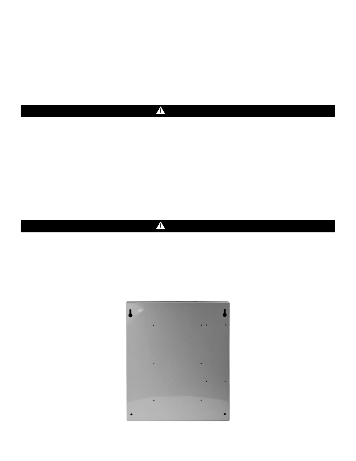
3.1 Mounting Holes
Mounting holes are provided in the DVP-120 case at the four corners. The top two are keyhole shaped so that the panel can be hung
and then the two bottom screws driven to hold the panel. See figure 3-1. The panel should be mounted with sufficient space around the
panel for access to Conduit entry holes provided on the top, bottom and right side of the panel.
Figure 3-1 Mounting Holes
7
Page 8
WARNING
3.2 General Wiring Information
High voltage terminals (120/240 VAC) are located within the DVP-120, presenting a hazard to service technicians. Only qualified
technicians should open the D VP-120 case and serv ice the internal circu its. Ensure power is r emoved from the DVP -120 prior to ser vicing
the unit.
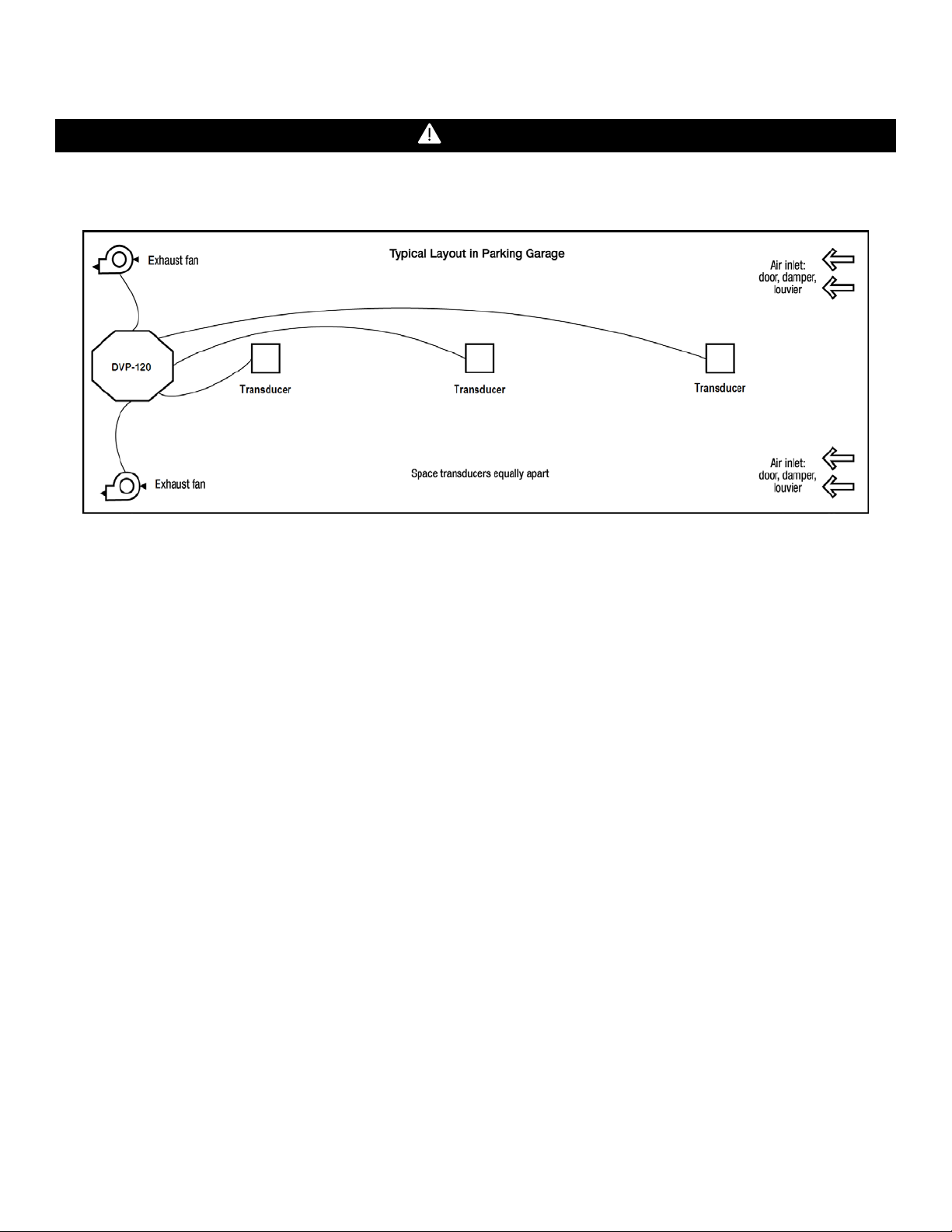
Figure 3-2 Typical Layout
With the exception of the safety ground, all field wiring is completed via modular connectors (provided). After wiring, simply plug the
modular connectors into the matching connectors on the printed circuit board (PCB).
Note: It is recommended to always install with wires enclosed within the rigid metallic conduit.
3.2.1 DVP-120
The power and signal connections to the remotely mounted sensors should be size AWG18 (minimum) for short runs. Refer to Table 32 for recommended wire gauges. Four conductor cables may be used in all cases since the DVP-120 employs DC power for remote
sensors to help prevent electrical noise from interfering with the sensor output signal.
Do not bundle sensor power and/or signal connections with other AC power cables to prevent electrical interference. If other AC power
connections must be bundled with the DVP-120 sensor cables, the sensor connections should be made with two twisted pairs of the
appropriate gauge, with an overall foil and braid shield. All shields should be terminated at the DVP-120 end of the cable only. A ground
stud is provided near the bottom left corner of the panel.
3.2.2 DVP-120B
The power connections to the MRS-485 and remote mounted sensors and should be size AWG18 (minimum) for short runs. Refer to
Table 3-2a for recommended wire gauges. The power for the MRS-485 adapter is connected via a two-terminal screw type connector,
12 to 24 VAC or 12 to 24 VDC and no polarity.
The MRS-485 adapter output is wired in the standard 2W-Modbus circuit definition with selectable built-in terminating resistors at the
ends of the RS-485 bus. It is recommended to always use twisted wires to reduce noise and allow for reliable data communication over
greater distances. For best performanc e use sh ielded 3-cond uctor wire w ith one twist ed pai r pr oviding a pair f or sign al (A & B), common
(COM) and shield ground (SHD) connections. Use at least 3-conductor wire with one twisted pair providing a pair for signal (A & B) and
common (COM) connections. The Macurco MRS-485 Modbus output is connected via a four-terminal screw type connector.
Running the Modbus cable adjacent to or in the same conduit with high voltage wires is not recommended as there may be interference
from the high voltages.
8
Page 9
Signal
Connector
Pin Number
Line (120/220/240/ 2 50 VAC)
AC~ 3 Neutral
AC~ 1 Ground
Ground Stud
n/a
3.3 Main Power Connec ti on
The main power cable should be routed int o the bott om left c onduit entry. Ma curco re commend s a minimum w ire size of A WG18 and the
wire insulator must be rated for 140°F (60°C) service. The modular connector will accept wire from 12 to 24 AWG. The safety ground
wire should be secured to the ground stud at the bottom left of the cabinet with the lock washer and nut supplied. Use a ring terminal for
the ground connection. Refer to Table 3-1 for DVP-120 power connections. The line and neutral wires should be stripped 1/4 in. (6.5
mm), insert the wire into the wire cavity of the modular connector and tighten the screw clamp. Ensure that the wire cannot be easily
pulled from the connector. Plug the modular connector into AC~ on the PCB and ensure that it latches into the header properly.
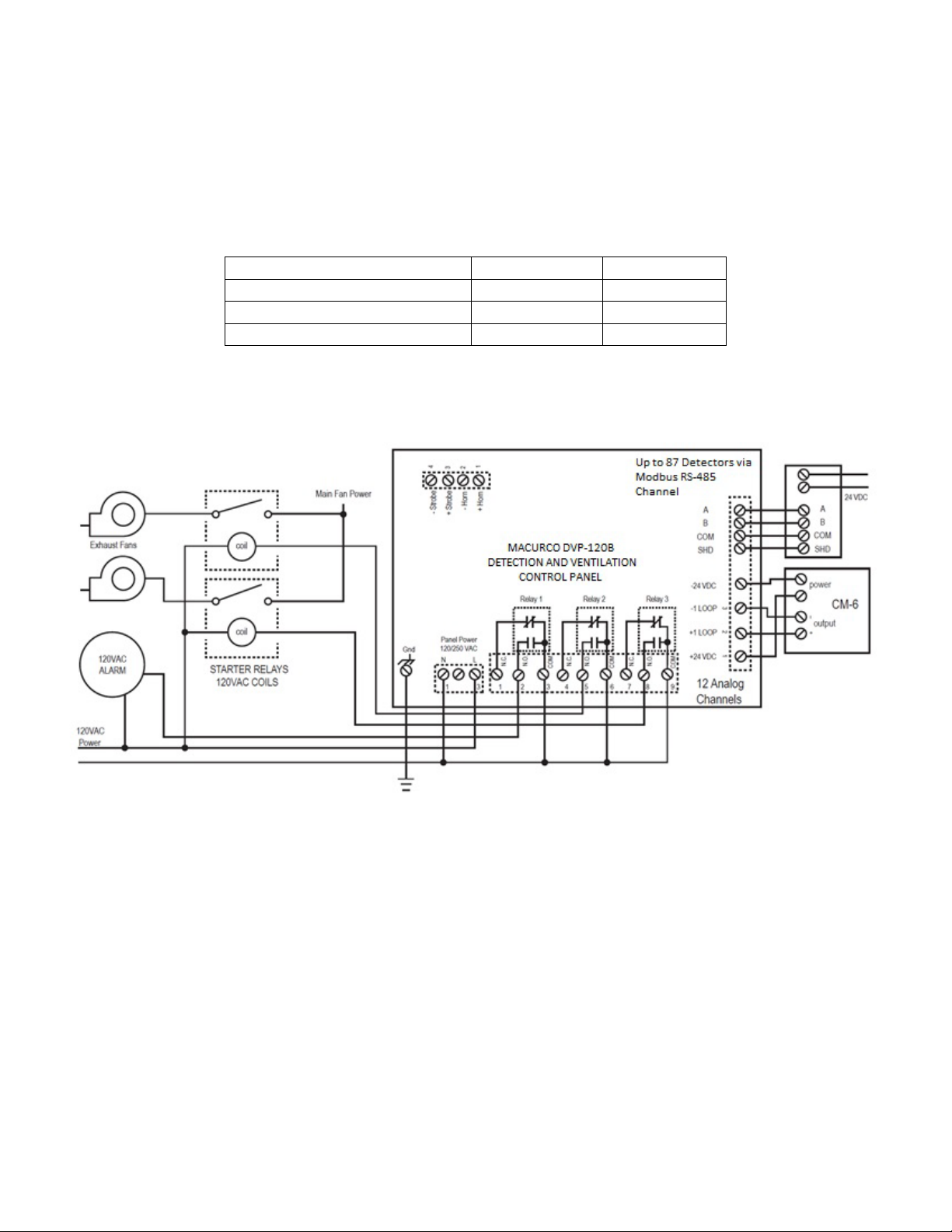
Table 3-1 Main Power Connections
Figure 3-3 System Wiring Diagram
3.4 Remote Sensor Connection
3.4.1 DVP-120
Each remote sensor is connected by a four-wire connection – two wires for DC power and two wires for the 4 – 20 mA loop connection.
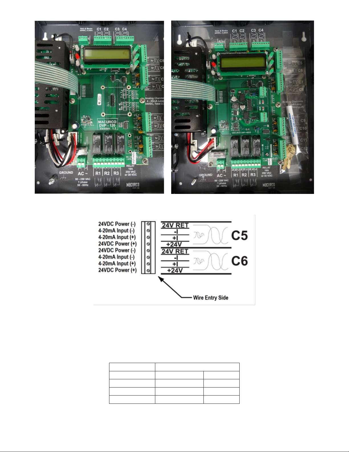
The sensors are connected to the control panel PCB with modular connectors, two sensors per connector. See Figure 3-5 for a view of
a typical sensor connector. Refer to Table 3-2 for wire size recommendations.
9
Page 10
Wire gauge
Maximum Run Length
(feet)
(meters)
18
500
152
16
800
244
14
1250
381
Figure 3-4 DVP-120 Internal View and DVP-120B with DVP-485 Modbus Adapter
Figure 3-5 Sensor Interface Connector – Channels 5 and 6
Each 8-terminal sensor modular connector may be disconnected from the PCB connector to ease wire installation. The terminals will
accept wire from 16 to 28 AWG. To install a wire, strip back approximately 0.25 in. (6 mm) of insulation and insert the bare wire into the
terminal. Tighten the screw clamp and ensure that the wire cannot be easily pulled from the connector. Connector to sensor C1 through
C12 correspondence to all 12 input channels.
Table 3-2 Recommended Wire Gauge
10
Page 11

Typical coverage for CO, CO2 and NO2 sensors is 5,000 sq. ft. (464.5 sq. m), 900 sq. ft. (83.6 sq. m) for combustibles and other toxic
gases (see the User Instructions for each sensor type for location and coverage details). Extra sensors may be needed near areas
where people work, such as toll booths. Macurco provides only the control panels and sensors. Fans, relays, and other devices are
provided by the contractor. See the appropriate building code for the size of fans and air changes per unit of time.
3.4.2 DVP-120B
A Modbus over Serial Line Cable should be shielded for best performance. The shield should be connected on each detector at SHD
terminal and connected to a ground terminal or chassis only at one end of the bus. An RS485-MODBUS must use a balanced pair (for
A-B) and a third wire (for the Common). For RS485-MODBUS, Wire Gauge must be chosen sufficiently wide to permit the maximum
length (1000 m or 3281ft). AWG 24 is always sufficient for the MODBUS Data. Category 5 cables may operate for RS485-MODBUS, to
a maximum length of 600 m 1968.5 ft. For the balanced pairs used in an RS485-system, wire with a characteristic impedance of higher
than 100 Ohms may be preferred, especially for 19200 and higher baud rates.
Note: It is recommended to always use twisted wires to reduce noise and allow for reliable data communication over greater distances.
Use at least 3-conductor wire with one twisted pair providing a pair for signal (A & B) and common (COM) connections.
For best performance use shielded 3-conductor wire with one twisted pair providing a pair for signal (A & B), common (COM) and shield
ground (SHD) connections.
Figure 3-6 MRS-485 wiring
3.4.2.1 Topology
An RS485-MODBUS configuration w itho ut repeat er has on e trunk cab le, alo ng whic h devi ce s are con necte d, dire ctly (d aisy cha inin g) or
by short derivation cables. The trunk cable, also named “Bus”, can be long. Its two ends must be connected on Line Terminations. (see
Line Termination - End of Line Resistor section). The use of repeaters between sev eral RS 485-MODBUS is also possible.
3.4.2.2 Length
The end to end length of the trunk cable must be limited. The maximum length depends on the baud rate, the cable (Gauge,
Capacitance or Characteristic Impedance), the number of loads on the daisy chain, and the network configuration (2-wire). For a
maximum 9600 Baud Rate and AWG26 (or wider) gauge, the maximum length is 1000m 3281ft. The derivations must be short, never
more than 20m 65.5ft. If a multi-port tap is used with n derivations, each one must respect a maximum length of 40m 131ft divided by n.
3.4.2.3 Grounding
The Common circuit (COM) must be connected directly to protective ground, preferably at one point only for the entire bus.
3.4.2.4 Power Wire
All field wiring is completed via modular connectors (provided). After wiring, simply plug the modular connectors into the matching
connectors on the MRS-485. The power connections to t he remotely mounted detectors s hould be s ize AWG18 ( minimum) for short runs .
Since Macurco detectors are rated for operation between 12 and 24 VDC or VAC, the voltage drop between the power supply and the
MRS-485 should not be an issue if the recommended power wire gauge guidelines below are followed. The terminals will accept wire
11
Page 12
from 16 to 28 AWG. To install a wire, strip back approximately 0.25 in. (6 mm) of insulation and insert the bare wire into the terminal.
Wire gauge
Maximum Run Length
(feet)
(meters)
18
263
80
16
418
127
14
665
203
12
1058
322
Tighten the screw clamp and ensure that the wire cannot be easily pulled from the connector.
3.4.2.5 Power Supply
Selection of a UL recognized NEC Class 2 power supply which can power 12 MRS-485 connected to 6-Series detectors.
• MRS-485 is rated 3.25W with a detector connected.
• The minimum power which the power supply needs to deliver is 12 detectors x 3.25 W/detector = 39W
So, a 24VDC, 60W power supply will work.
Table 3-2a Wire selection for a 60W power supply
3.4.2.6 Relay Connection
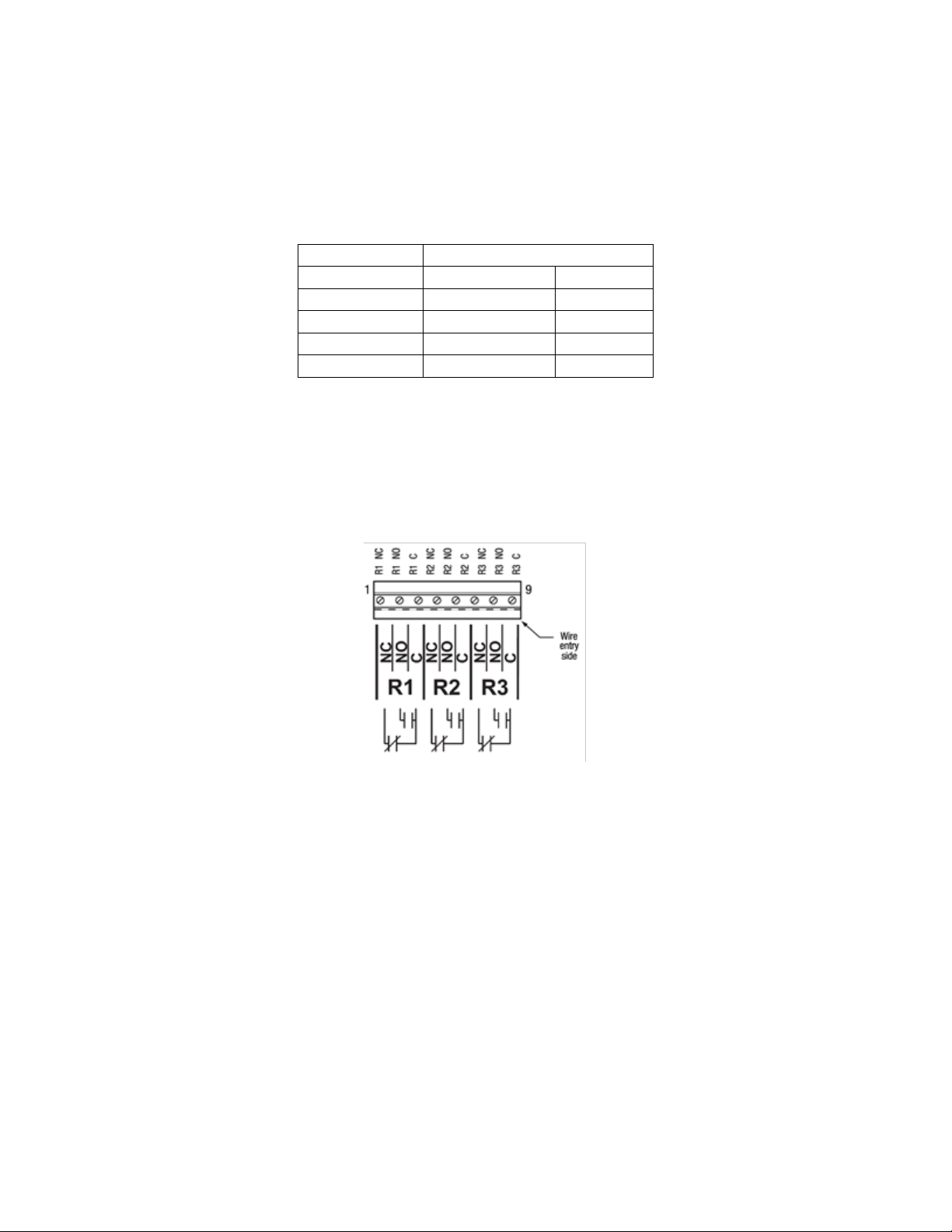
All poles of the three relays are available at the modular connector R1 R2 R3 (see Figure 2 for details). R1 R2 R3 is a 9-position variant
of the high voltage modular connector used for power input. Each terminal can accommodate a wire size from 12 to 24 AWG.
Figure 3-7 Relay Connector
To install the wiring for the relays, disconnect the connector from the header on the PCB. Strip the insulation off each wire back
approximately 1/4 in. (6.5 mm), insert the bare wire into the terminal and tighten the screw clamp. Ensure that the wire cannot easily be
pulled from the connector.
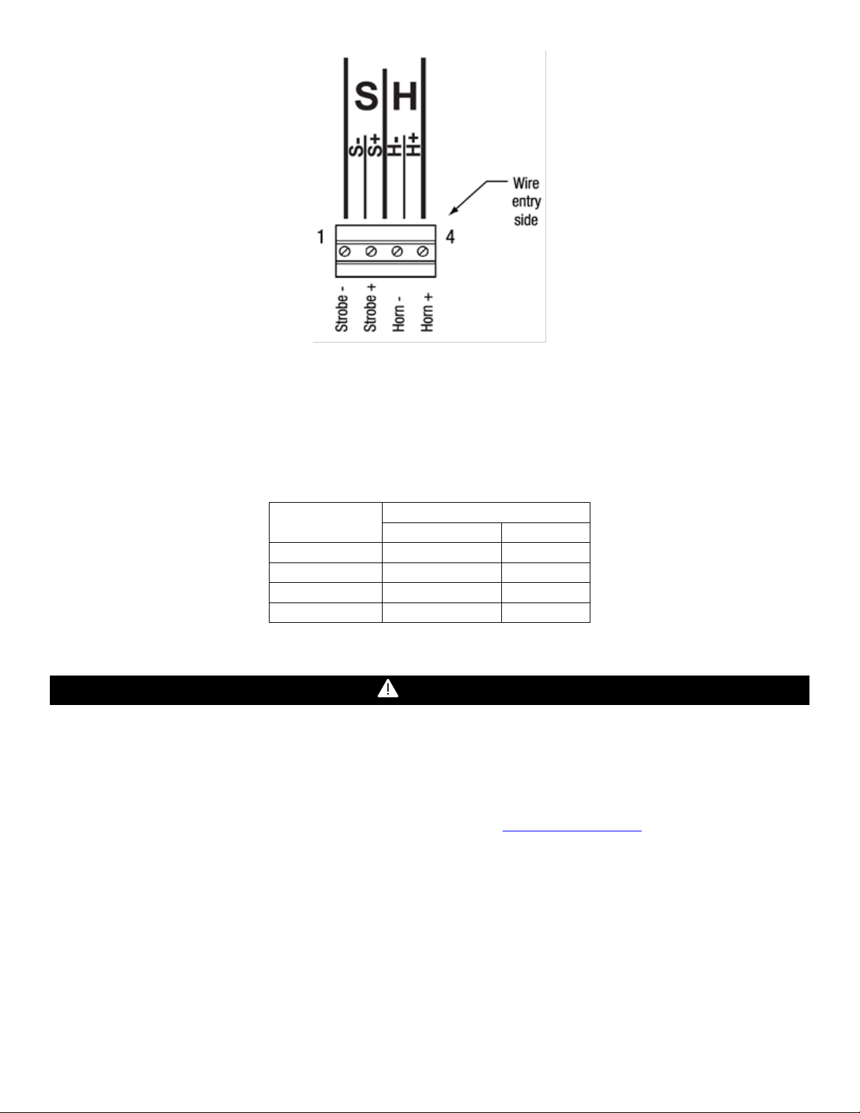
3.4.2.7 Horn & Strobe Connection
The external horn and strobe connections are available at the modular connector S H (see Figure 2 for details). S H as a 4-position
connector, similar to the sensor interface connectors.
12
Page 13
Maximum Run Length
(feet)
(meters)
24
200
61
22
340
103
20
480
147
18
850
215
WARNING
Figure 3-8 Horn & Strobe Connector
To install the wiring for the horn or strobe, disconnect the connector from the header on the PCB. Strip the insulation off each wire back
approximately 0.25 in. (6 mm), insert the bare wire into the terminal and tighten the screw clamp. Ensure that the wire cannot eas ily be
pulled from the connector. When all wire s are connected, sea t the modular connector into the PCB header; ensur e that the latch engage s.
Refer to Table 2 3 for recommended wire gauge vs. run length for the horn & strobe functions (maximum 2.5-volt drop in the wire). The
Strobe and Horn circuits are Class 2 control circuits, so Class 2 conductors should be used.
Wire gauge
Table 3-3 Wire gauge for Horn & Strobe functions
Immediately exit any environm ent that cau ses an a larm cond i tion on the sen sor. Fa ilure to d o so may re sult in serious inj ur y or death.
3.5 Interfacing Macurco Sensors
3.5.1 DVP-120
Macurco sensors with current loop outputs may be used with the DVP-120. See http://www.macurco.com
Macurco gas transducers. See specific information on other manufacturer’s transducers.
Power connections to Macurco sensors used with the DVP-120 are polarity-insensitive (no polarity) since a bridge rectifier is connected
to the power input terminals. All sensors used with the DVP-120 panel employ screw clamp terminal blocks for power and signal
connections. The polarity of the current loop connections is marked on the printed circuit b oard of the sensor.
3.5.2 DVP-120B
The Macurco MRS-485 Adapter converts the Macurco 6-S er ies 4-20mA analog output to a digital output for use with the DVP-120B and
other addressable network systems
13
for information on compatible
Page 14
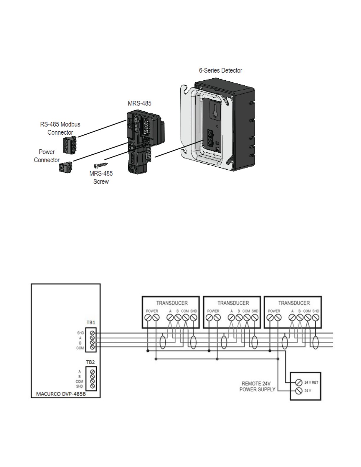
1. Remove the 4-20mA/Power plug from the Macurco 6-Series gas detector
2. Plug the MRS-485 adapter into the empty socket.
3. Install the provided MRS-485 screw.
4. See the wiring diagram for wire connection.
Figure 3-9 MRS-485 Installation
3.5.2.1 Connection
The Macurco MRS-485 output is connected via a four -termina l screw t ype conne ctor. The MR S-485 adapter is wired in the standard 2W Modbus circuit definition wi th s electable buil t-in t ermin ating re sistor s at the end s of the RS-4 85 bu s. The pow er for t h e MR S-4 85 ada pte r
is connected via a two-terminal screw type connector, 12 to 24 VAC or 12 to 24 VDC and no polarity.
Note: Running the Modbus cable adjacent to or in the same conduit with high voltage wires is not recommended as there may be
interference from the high voltages.
Figure 3-10 Modbus Wiring
14
Page 15
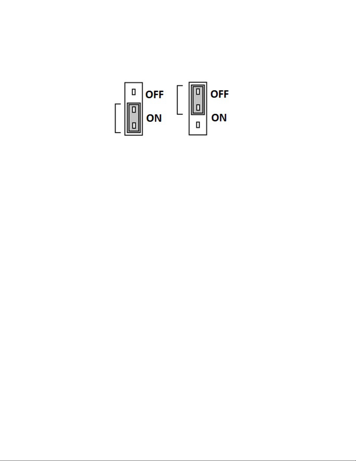
3.5.2.2 Line Termination - End of Line Resistor
The MRS-485 and DVP-485B adapters are wired in the standard 2W-Mo dbus circuit definitio n with selectable bui lt-in terminat ing resistors
at the ends of the RS-485 bus. The MRS-485 and DVP-485B adapters provide integral termination for the end of line resistors (EOL).
The terminations use 4-pin connector (for MRS-485) and 3-pin (for DVP-485B) with a jumper to select termination: The user selects no
termination or one of the two Modbus line termination options. The MRS-485 has two line termination options provided and DVP-485B
adapters have 120-ohm termination options provided onboard.
Figure 3-11 End of Line Resistor
Place the EOL jumper on one of the following positions:
3.5.2.3 Determining EOL Use
At the baud rate of 19200 (default baud rate for Macurco MRS-485 and D VP-485) and with cables less th an 1,000 ft. in length, terminat ion
resistors are not recommended.
At the baud rate of 19200 and with cables longer than 1,000 ft., termination resistors are recommended.
It is recommended to use an RS-485 type of cable and 120 ohms for termination resistor.
An RS-485 network requires a 3-wire cable: a twisted pair and a third wire. It is difficult to tell whether shielding is required or not in a
particular system until problems arise, so it is recommended to always use shielded cable.
When using termination resistors use only 2 resistors, one at each end of the RS-485 transmission line (i.e. 1 at the DVP-485B and 1 at
the last/farthest MRS-485).
3.5.2.4 Using Other Baud Rates
For any other baud rates calculate when (at what length) termination resistors are required. Calculate the length as 1000 ft. divided by
the ratio between the new baud rate and 19200.
For example, if new baud rate is 9600
1000 / (9600/19200) = 1000 / 0.5 = 2000 (ft.)
Use termination resistors when cables are longer than 2000 ft.
For example, if new baud rate is 38400
1000 / (38400/19200) = 1000 / 2 = 500 (ft.)
Use termination resistors when cables are longer than 500 ft.
Note: Other manufacturers may have different recommendations on wire length and EOL resistor usage.
15
Page 16
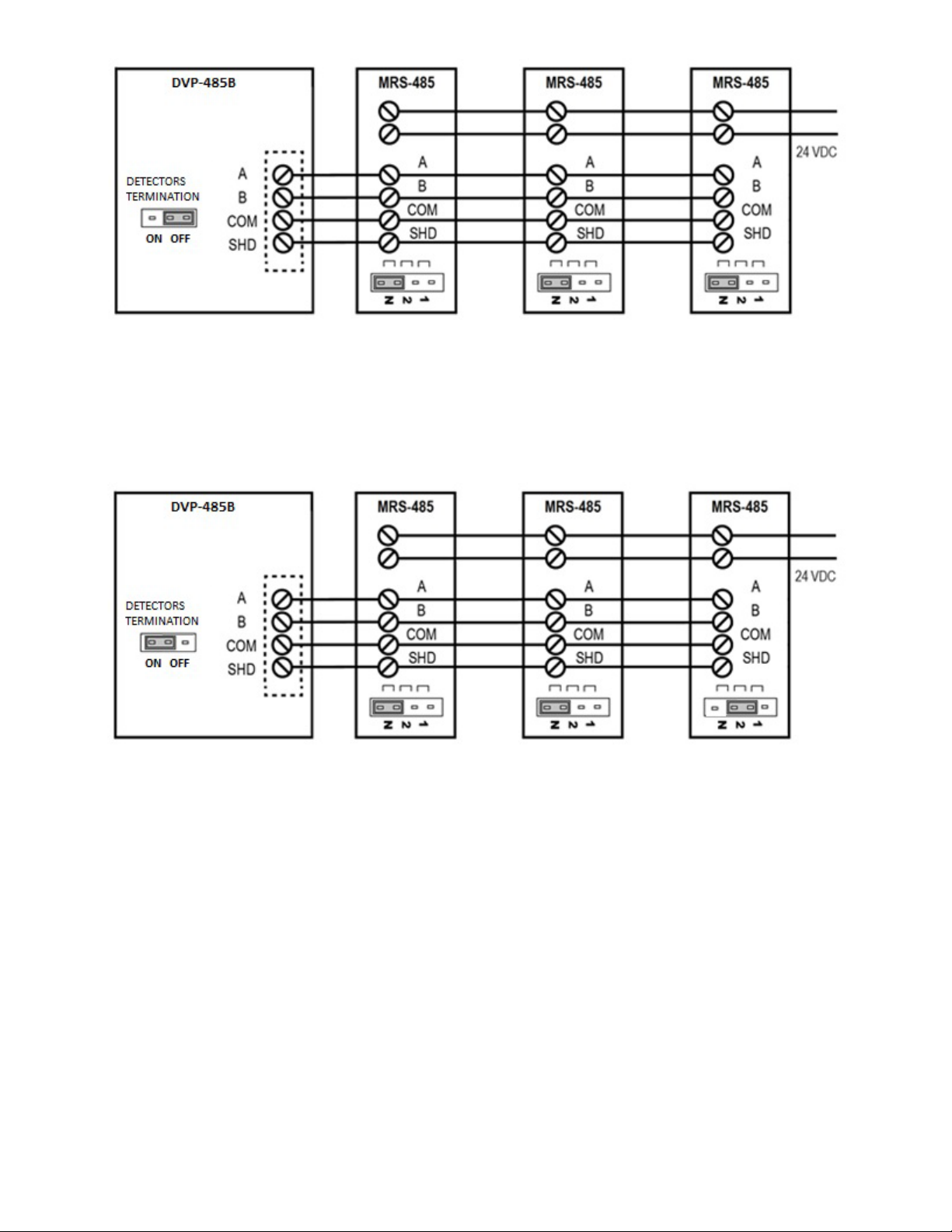
Figure 3-12
At 19200 baud rate (default), 1000 ft or less and using RS-485 or Cat-5 type cable
Figure 3-13
At 19200 baud rate (default), more than 1000 ft and using RS-485 type cable
16
Page 17
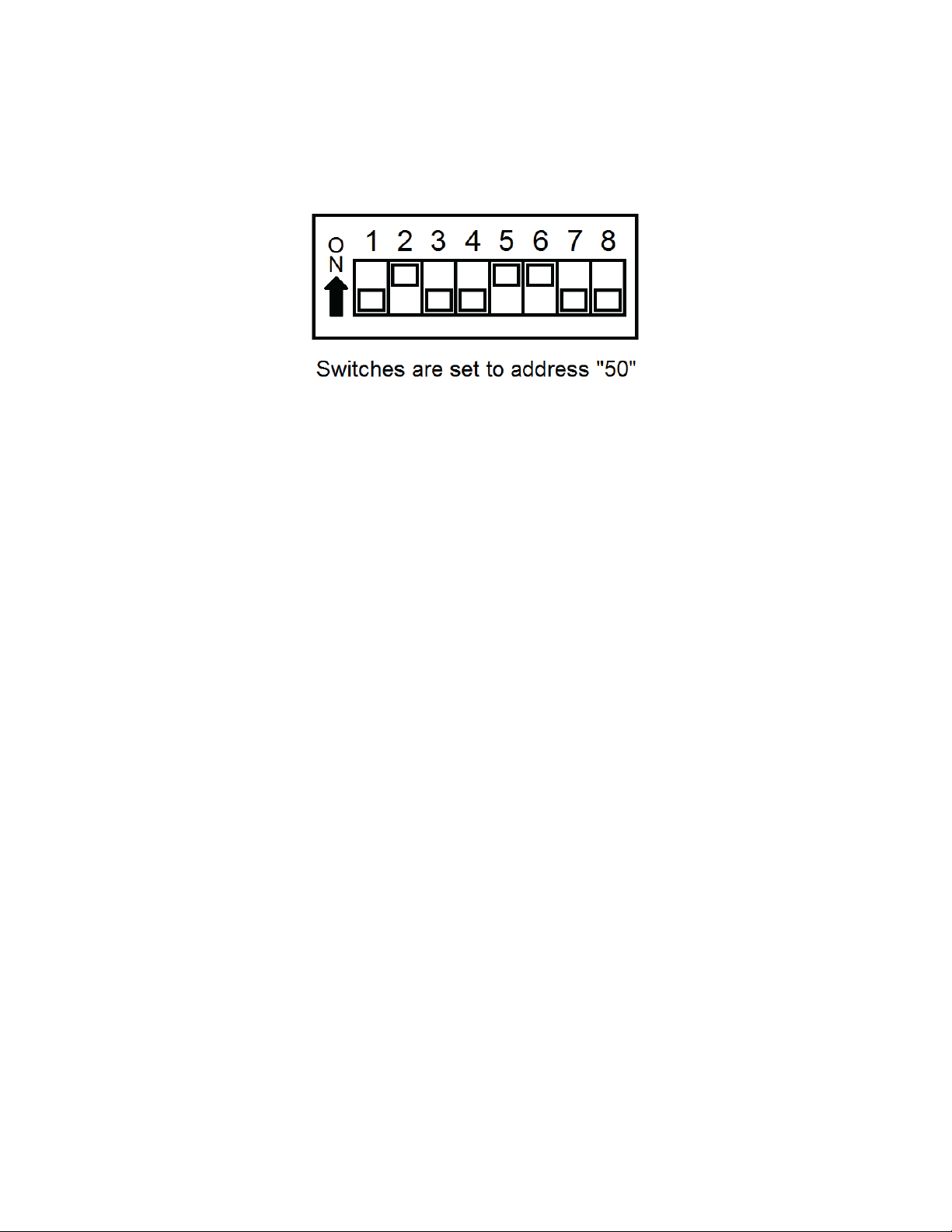
3.5.2.5 DIP Switches and Addressing
Each MRS-485 (and the partner gas detector) must be configured to a unique address. If there are 10 detectors on the serial lin e, t hen
10 unique addresses must be used, one for each detector. To set the address, use the eight DIP switch positions. For each unit choose
the value from 13 to 99 (see chart) and set the eight switches to match the address. UP means ON or 1 and DOWN means OFF or 0.
For example, to configure a unit as address “50”, set switches “2, 5, 6” (see table) to ON or in the up position (01001100). See page 11
for a list of applicable addresses and dip-switch settings.
13 = 1, 3, 4
14 = 2, 3, 4
15 = 1, 2, 3, 4
16 = 5
17 = 1, 5
18 = 2, 5
19 = 1, 2, 5
20 = 3, 5
21 = 1, 3, 5
22 = 2, 3, 5
23 = 1, 2, 3, 5
24 = 4, 5
25 = 1, 4, 5
26 = 2, 4, 5
27 = 1, 2, 4, 5
28 = 3, 4, 5
29 = 1, 3, 4, 5
30 = 2, 3, 4, 5
31 = 1, 2, 3, 4, 5
32 = 6
33 = 1, 6
34 = 2, 6
35 = 1, 2, 6
36 = 3, 6
37 = 1, 3, 6
38 = 2, 3, 6
39 = 1, 2, 3, 6
40 = 4, 6
41 = 1, 4, 6
42 = 2, 4, 6
43 = 1, 2, 4, 6
44 = 3, 4, 6,
45 = 1, 3, 4, 6
46 = 2, 3, 4, 6
47 = 1, 2, 3, 4, 6
48 = 5, 6
49 = 1, 5, 6
50 = 2, 5, 6
51 = 1, 2, 5, 6
52 = 3, 5, 6
53 = 1, 3, 5, 6
54 = 2, 3, 5, 6
55 = 1, 2, 3, 5, 6
56 = 4, 5, 6
57 = 1, 4, 5, 6
58 = 2, 4, 5, 6
59 = 1, 2, 4, 5, 6
60 = 3, 4, 5, 6
61 = 1, 3, 4, 5, 6
62 = 2, 3, 4, 5, 6
63 = 1, 2, 3, 4, 5, 6
64 = 7
65 = 1, 7
66 = 2, 7
67 = 1, 2, 7
68 = 3, 7
69 = 1, 3, 7
70 = 2, 3, 7
71 = 1, 2, 3, 7
72 = 4, 7
73 = 1, 4, 7
74 = 2, 4, 7
75 = 1, 2, 4, 7
76 = 3, 4, 7
77 = 1, 3, 4, 7
78 = 2, 3, 4, 7
79 = 1, 3, 4, 7
80 = 5, 7
83 = 1, 2, 5, 7
84 = 3, 5, 7
85 = 1, 3, 5, 7
86 = 2, 3, 5, 7
87 = 1, 2, 3, 5, 7
88 = 4, 5, 7
89 = 1, 4, 5, 7
90 = 2, 4, 5, 7
91 = 1, 2, 4, 5, 7
92 = 3, 4, 5, 7
93 = 1, 3, 4, 5, 7
94 = 2, 3, 4, 5, 7
95 = 1, 2, 3, 4, 5, 7
96 = 6, 7
97 = 1, 6, 7
98 = 2, 6, 7
99 = 1, 2, 6, 7
3.5.2.6 Normal MRS-485 Operation
The MRS-485 will monitor the 4-20 mA current output of the detector. At power up and during its warm-up period, the 6-Series detector
will communicate its sensor type over the 4-20 current output using a custom protocol. The MRS-485 will automatically register each 6Series detector as it is programmed with information about all the detectors to which it can be connected. The MRS-485 will use this
information to determine the gas level sensed by the 6-Series detector by measuring the 4-20 mA current-loop output during normal
operation of the detector.
• When the LED is solid GREEN, the operation is normal, the MRS-485 knows the detector type, no errors are
detected and no MODBUS data are being received or transmitted over the RS-485 line.
• When the LED is GREEN with random bursts of AMBER, the operation is normal and now data are being received
or transmitted over the RS-485 line. The AMBER LED will come on anytime that there is data traffic
17
Page 18
4 Operations
D V P - 1 2 0 V e r 1 . 0 7
WARNING
D V P - 1 2 0 V e r . 1 . 0 7 W a r m - u p 2 : 3 0
4.1 Initial Operating Mode
When power is first applied to the DVP-120, a few simple self-tests will be performed, and the system will cycle through all status lights,
and display the system model and firmware version number (Figure 4-1). The system will then proceed to normal mode if the operating
parameters have been entered.
Figure 4-1 Model Display
Each time the unit is turned on it performs a self-test, which activates the audible and visual alarms . If the self-test fails, or all the alarms
do not activate, do not use. Failure to do so may adversely affect product performance and result in serious injury or death.
If the user has not entered any parameters, the system WILL NOT be controlling the ventilation system. The relays WILL NOT actuate,
and the horn and strobe outputs WILL NOT be powered. The power status light will show NORMAL (steady green) and the system will
immediately enter the CONFIGURATION mode, see section 4.2 for details to set the configuration parameters.
If a valid set of configuration parameters have been entered, the panel will wait for all sensors to warm up. During this time, the display
will show a count-down, minutes and seconds, until the end of the warm-up period, (Figure 4-2).
Figure 4-2 Warm=Up display
During the warm-up period, the keypad will be locked. When the warm-up period ends, the LCD will start showing the normal display.
4.1.1 Status Light Display
The POWER, ALARM/WARNING, SILENCE, RELAY 1, RELAY 2 and RELAY 3 status lights indicate the system status and provide the
following data:
• POWER
o Green (steady) – Power is good and there are no trouble indic ati o ns
o Yellow (steady) – Trouble is indicated by a transducer or the panel itself
• ALARM/WARNING
o Off – All indicated gas levels are below the warning level
o Red (steady) – One or more gas levels are at or above the alarm level
o Amber (steady) – One or more gas levels are at or above the warning level
• HUSH
o Off –There are no silenced alarms or warnings
o Red (flashing) –There are alarms, warnings and/or troubles that have been silenced (gas levels may or
may not remain or continue to be at an alarm or warning levels)
• RELAY 1
o Off – Relay 1 is not on
o Green (steady) – Relay 1 is on
• RELAY 2
o Off – Relay 2 is not on
18
Page 19
o Green (steady) – Relay 2 is on
• RELAY 3
o Off – Relay 3 is not on
o Green (steady) – Relay 3 is on
The overall system status is visible at a distance via the status lights as described above. More detailed system information is displayed
on the LCD, which can show the status of each relay and sensor. A typical status display is shown in Figure 4-4.
4.1.2 User Interface
The LCD display is used to show detailed information about th e status of the contro l system and the configuration parameter s to the user.
The keypad is used to select the information displayed and to enter the configuration parameters, which are stored in the DVP-120
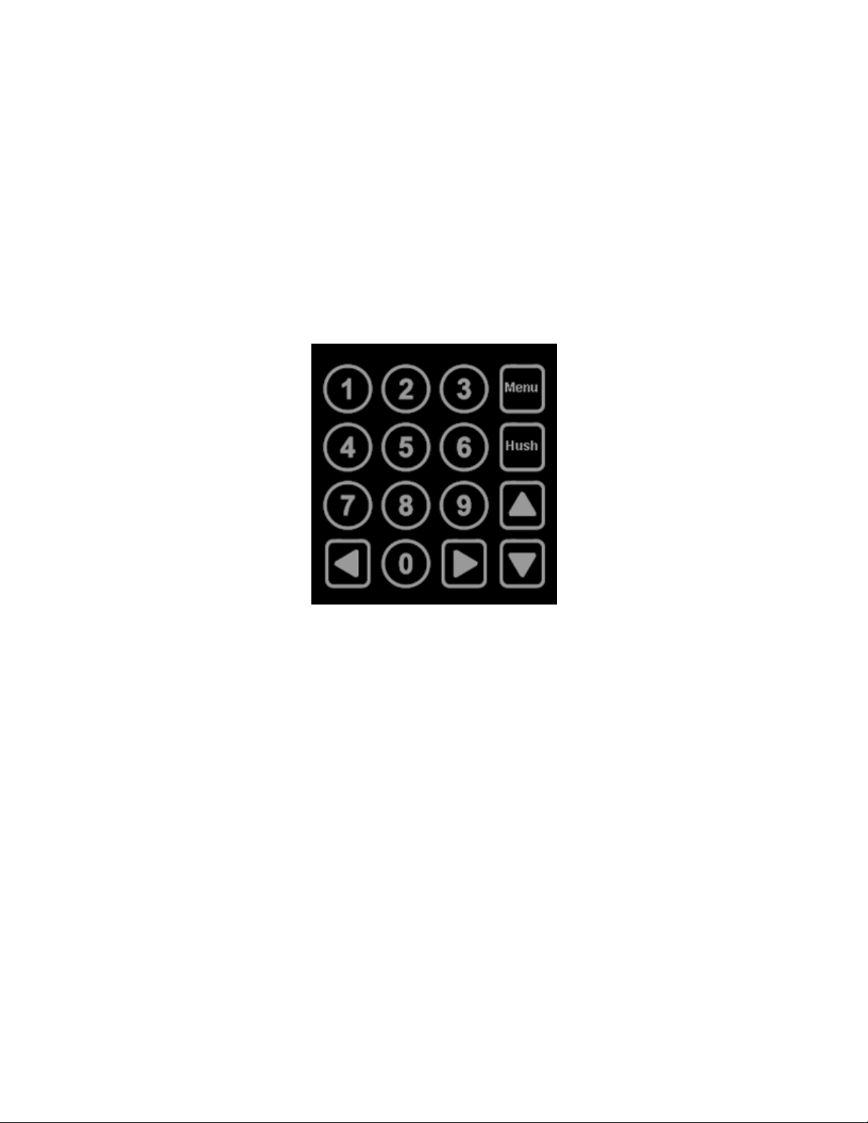
memory. The keypad consists of the usual ten-digit keys, four direction keys, plus a MENU key that is used to access the configuration
menu and a HUSH key that will silence the audible alarm indicators. In normal mode, holding the zero key for three (3) seconds can be
used to lock the keypad against accidental (or unauthorized) use. See Section 4.5 for details.
Figure 4-3 Keypad layout
4.1.3 Cursor Keys
In normal mode, (no warnings or alarm s ind icat ed), the up an d d own cur sor ke ys wi ll s crol l the d isplay to an y con figure d s ensors’ stat us .
In normal mode, the left and right cursor keys will scroll through the status of each of the relays. When the left (or right) key is used to
scroll to another relay, the display will remove the underlining under the sensor number and underline the relay number; this indicates
that the digit keys can be used to jump directly to a par ticular relay’s stat us. When the up or d own key is again used the di splay will switch
back to the digit keys jumping to a particular sensor.
4.1.4 MENU Key
The MENU key has three functions. First, when the system is presenting the normal display, pressing the MENU key will cause the
system to shift to the Configuration Menu. The second function of the MENU key is to return to the next-higher menu level, e.g. from the
sensor configuration menu to the system menu, or from the system menu out to normal mode. If in the middle of entering a multi-digit
parameter, the MENU key also cancels any changes to the parameter. When the MENU key is used to return to normal mode, any
changed configuration parame ters are saved in the DVP-120 ’s memory. The third function of the MENU ke y is to chang e the LCD contr ast
by holding the MENU key for five (5) seconds, at which point the LCD will prompt for further activities, see sections 4.4 for more detail.
4.1.5 HUSH Key
The HUSH key is only used to silence the audible indicators (internal buzzer and possible external Horn and Strobe devices). Pressing
and releasing the button will silence the internal buzzer. The HUSH button must be held for 3 seconds to silence the Horn and Strobe
devices.
19
Page 20

M O N 1 0 : 2 3 R 1 O F F S 0 1 C O 5 P P
M
S h o w S e n s o r _ 1
A L A R M C O S E N S O R 0 2
WARNING
4.1.6 Normal Status Display
Figure 4-4 Normal System Display
The display shows the day of the week and the time of day, in 24-hour format. It also shows the status of one of the relays, R1 in this
example, and the type and indi cated the gas concentration of one of the configured sen sors , S 01 is a C O sen sor ind icatin g 5ppm i n thi s
example.
Notice in Figure 4-4 that the digits 0 1 are underlined; this indicates that the digit keys can be used to jump directly to another sensor’s
status. When the first digit is pressed, the display will prompt for the second digit of the target sensor.
Figure 4-5 Sensor Prompt
In this example, the first digit entered was 1. Since the DVP-120 can handle 12 sensors, the first digit for a sensor number is either 0 or
1. The leading zero must be entered when selecting a sensor less than ten. When the second digit is entered, the normal display will be
restored; showing the type and value of the selected sensor.
As mentioned above, the left an d right scroll keys will display the next or previous relay’s stat us. The display w ill also change the und erline
to indicate that the digit keys (zero, one and two) can be used to jump directly to a particular relay. Since only one digit is needed to
select a relay, the system does it immediately rather than prompting to show the relay.
If the sensor is indicating a gas level that is great er than the alarm or warn ing leve ls, the g as reading will altern ate wit h the word s ALARM
or WARNING as appropriate. If a sensor fails, a connection is lost or the panel itself detects a failure of its own, the panel will enter
TROUBLE mode and the gas reading will be replaced by the word TROUBLE (the TROUBLE status condition is discussed in section
4.1.6 Trouble Status Display
).
4.1.7 ALARM Status Display
When any sensor indicates a gas level that is at or above the configured alarm level for the sensor, the panel will enter ALARM mode,
during which the internal buzzer will sound, the alarm lamp will be red and the LCD will show the sensor type and channel number.
Figure 4-6 Alarm Display
The display will cycle through all sensors that are signaling alarm levels, at five seconds per display. Pressing any key (except HUSH)
will advance the display to the next sensor that is signaling an alarm level.
Do not cover or obstruct audible alarm opening or visual alarm LED. Doing so may adversely affect product performance and result in
serious injury or death.
If an external horn and/or strobe are conn ected and configur ed t o signal a n a larm con dition, they will also so und when an alarm condit ion
occurs, after a delay if that configuration option is used.
20
Page 21

When the HUSH key is pressed, the internal buzzer will be silenced for five (5) minutes. If the horn or strobe turn on delays have not
A L A R M S I L E N C E D F O R 5 M I N U T E S
W A R N I N G C O S E N S O R 0 2
W A R N I N G S I L E N C E D F O R 1 5 M I N U T E S
finished then they will also be silenced. If the delays have finished the HUSH key must be held for three (3) seconds in order to silence
the horn and strobe.
When all indicators have been silenced, the display will show that alarms have been silenced for five minutes. After any key is pressed
(or five seconds), the display will return to normal mode.
Figure 4-7 Alarm Silenced message
If Relay 1 is configured as an ALARM relay, it will be turned on when an alarm condition is recognized.
4.1.8 Warning Status Display
When any sensor indicates a gas level that is at or above the configured warning level for the sensor, the panel will enter WARNING
mode during which the internal buzzer will sound, the alarm/warning lamp will be amber, and the LCD will show the sensor type and
channel number.
Figure 4-8 Warning display
The display will cycle through all sensors t hat are s igna ling war ning levels , at fiv e se cond s per display. P re ssing any key (except HUS H)
will advance the display to the next sensor that is signaling a warning level.
If the buzzer and/or an external horn and/or external strobe are connected and configured to signal a warning condition, they will also
sound when a warning condition occur s. Ther e is a confi gur able del ay bef ore the h or n or s trobe w ill sound, see s ectio ns
Horn Submenu, 4.3.6 Configure Strobe Submenu, and 4.3.4 Configure Relays, Horn & Strobe.
When the HUSH key is pressed, the internal buz zer w ill be sil enced for fif teen (1 5) m inute s. I f the horn or stro b e turn on delays ha ve no t
finished, then they will also be silenced. If the delays have finished, the HUSH key must be held for three (3) seconds in order to silence
the horn and strobe.
When all indicators have been silenced, the display will show that warnings have been silenced for fifteen minutes. After any key is
pressed (or five seconds) the display will return to normal mode.
Figure 4-9 Warning Silenced message
4.1.9 Trouble Status Display
4.3.5 Configure
If a sensor fails, a connection is lost or the panel itself detects a failure of its own, the panel will enter TROUBLE mode during which the
internal buzzer will sound, the power lamp will be yellow, and the LCD will display the specific sensor identified.
Possible trouble conditions are:
• Any configured channel has less than 4 mA flowing in the current loop
• A sensor is reporting a trouble condition
• Any configured channel wiring is open.
• Internal controller board problems are detected.
21
Page 22

T r o u b l e C O S e n s o r 0 2
T R O U B L E S I L E N C E D F O R 8 H O U R S
Z O N E S I G N A L Z O N E 1
Figure 4-10 Trouble display
The display will cycle through all trouble ind ications, at five seco nds per display. Pressing an y key (except HUSH) w ill advance the displa y
to the next trouble indicator.
If an external horn and/or strobe are conn ected and configur ed t o signal a trou ble cond ition, they will also so und wh en a tro uble conditio n
occurs, after a delay, if that configuration option is selected.
When the HUSH key is pressed, the internal buzzer will be silenced for eight (8) hours. If the horn or strobe turn on delays have not
finished then they will also be silenced. If the delays have finished, the HUSH key must be held for three (3) seconds in order to silence
the horn and strobe.
When all indicators have been silenced, the d isp lay will show that t roub le indicatio ns h ave b een s ilen ced f or ei ght ho urs. A ft er any key is
pressed (or five seconds), the display will return to normal mode.
Figure 4-11 Trouble Silenced message
4.2 Ventilation Control
The ventilation control functio n operates in dependentl y from the alar m function. It pr ovides the abi lity to config ure the DVP -120 for control
of one to three zones. Each zone can respond to gas levels indicated by one or more of the sensors, with configurable turn on and turn
off concentrations (rising and falling) for each gas type. Each zone can also be controlled based on the time of day.
Each zone can be configured to control one, two or all three of the relays and the external horn and strobe if desired. When more than
one zone is controlling a relay it only takes one zone to activate the relay, but all controlling zones must release the relay before it will
turn off.
Each of the relays, horn, and strobe has independent turn-on delays (to ignore short duration, transient gas signals) and turn off delays
(to ensure minimum run times for fans that must run for internal cooling).
4.2.1 Zone Signal Display
When a zone is controlling the horn or strobe and they are activated, the panel will enter ZONE SIGNAL mode during which the horn
and/or strobe will be turned on and the LCD will show the zone that is signaling.
Figure 4-12 Zone Signal display
The display will cycle t hrough all zones that are contr olling th e horn or strobe and ar e signal ing, at f ive seconds per displ ay. P ressing an y
key (except HUSH) will advance the display to the next zone that is signaling.
When the HUSH key is held for three (3) seconds, the horn and/or strobe will be silenced for fifteen (15) minutes. When silenced, the
display will show that zone si gnals have bee n silenced for f ifteen minu tes. After any key is p ressed (or five s econds) the di splay will retu rn
to normal mode.
22
Page 23

Z O N E S I L E N C E D F O R 1 5 M I N U T E S
Figure 4-13 Zone Signal Silenced message
5 S E N S O R S F O U N D 3 R E L A Y S F O U N D
S a v e C o n f i g . ? ( 0 = N O , 1 = Y E S )
4.3 Setting the System Configuration
The configuration menus can be entered from nor mal mode by press ing the MENU key. Wh ile in configuration mode, th e user can review
all configuration parameters to check the current operating conditions. As an aid when configuring the control panel, the first entry in the
top menu summarizes the number of se nsor s and rel ays t h at the pane l is cur rentl y reco g nizing. B e sure th at the 4-2 0m A o utput on ea ch
sensor is set to “On”.
Figure 4-14 Hardware Summary
The MENU key is also used to return to a higher-level menu and final ly ex it the conf igurat io n menus ba ck to norm al mode . When exiti n g
from the menu system to normal mode, if any configuration changes have been made, the panel will ask whether changes are to be
saved.
Figure 4-15 Save Configuration? Prompt
Pressing the zero (0) key at this point will cancel all changes except time and day of week. Pressing the one (1) will save all changes to
memory, and the changes will then become effective in controlling the ventilation system.
While the DVP-120 is in the configuration mode, alarm and ventilation control functions continue in the background with the previously
set configuration values. In particular, if an alarm condition is detected, the alarm lamp, the buzzer, the horn and the strobe will operate
as configured but the LCD will not display the detailed information. The HUSH key can be used to silence any alarm, warning or trouble
indicators without having to exit the configuration mode. If the MENU key is used to exit the configuration mode before using the HUSH
key, the LCD will display the cause of the audible indicator.
The numeric keys are use d to change the part icul ar par amet e r di splayed. The un derl ined char acter, or spa ce, on e ach display, indicates
what will be changed by the digit keys.
The left and right cursor keys will enter the particular submenu and scroll through the items of the same type where appropriate, e.g.
enter the Configure Sensors submenu and scroll through the parameter lists for the existing sensors.
The up cursor key scrolls through the menu entries in the order listed here, while the down cursor key scrolls in the reverse order.
Changing the configuration parameters requires the entry of a password before changes can be made. The default password is 1234.
See Figure 3-21 for an example of the password prompt.
In many cases, the parameter is entered as a string of digits, but some parameters are selected by pressing a single key, e.g. pressing
1 selects Monday, 2 selects Tuesday, etc.
4.3.1 System Menu
The top menu level allows the user to select:
• Configure System
23
Page 24

• Configure Sensors
Baud Rate
Reading Retries
19200 (Default)
12 (Default)
9600
8
4800
5
T i m e : 2 2 : 5 5 D a y : T u e s d a y
T i m e : 0 1 : 5 5 D a y : T u e s d a y
• Configure Relays, Horn & Strobe
• Configure Zones
• Configure Signals
The up and down cursor keys can be used to scroll through the entries in the list, while the left or right key will enter the particular
submenu.
The MENU key will return to normal mode. If any configur ation parameters have been chang ed, the panel will prompt to save the changes.
If the changes are saved, this is the poi nt at which they beco me effective in control ling the ventilation syste m and for alarm level detect ion.
Note that changes to the time and day of week are not considered configuration items; they are saved as soon as they are entered.
NOTE:
For DVP-120B, if baud rate for the panel is changed then “Reading Retries” Modbus parameter must be updated as per the following
table.
Figure 4-16 BACnet baud rate
4.3.2 Configure System Submenu
The system configuration submenu provides entries to:
• Set the time of day, 24-hour format
• Set the day of the week, day 1 is Monday
• Load Default Configuration
• Change Password
• Configure Sensor Type
4.3.2.1 Set Time of Day
Figure 4-17 Set Time of Day
This display example shows that the time is 22:55 (10:55 PM). The underlined characters indicate that the numeric keys can be used to
set the current time of day. When the first digit is entered (and after the password is entered if required), the display will change to show
that the “hour” portion of the time is currently being entered.
In this example, the first digit entered was 1 (one), and the panel is waiting for the second digit of the hour to be entered. If the second
digit is not entered within five seconds, the time will revert to the previous value. After the second digit of the hour is entered, the display
will prompt for the “minute” entry:
Figure 4-18 Enter Hours
24
Page 25

T i m e : 1 6 : 5 5 D a y : T u e s d a y
Figure 4-19 Enter Minutes
T i m e : 2 2 : 5 5 D a y : 2 T u e s d
a y
1 L o a d D e f a
u l t C o n f i g u r a t i o n
In this example, the hour (16) has been accepted and the panel is waiting for the minute to be entered. If no digits are entered within 5
seconds, the entry will be finished without changing the minute; however, the hour will be changed to the value entered.
Note that the time is saved as soon as the fourth digit is entered.
4.3.2.2 Set Day of Week
Figure 4-20 Set Day of the Week
This display example shows that T uesda y is the curre n t day of the week. Th e un derl ine ch ar acter in dicate s that the da y can b e chan ged
by entering the corresponding digit:
• 1 Monday
• 2 Tuesday
• 3 Wednesday
• 4 Thursday
• 5 Friday
• 6 Saturday
• 7 Sunday
Note that the day of the week is saved as soon as the digit is entered.
4.3.2.3 Load Default Configuration
Figure 4-21 Load Default Configuration
When the number one (1) digit is pre sse d, the pane l will pro mpt for t he pa ssword, even if i t has be en en tered p r eviou sly. I f the pa ssw ord
is entered correctly, the panel will overwrite the existing configuration with the default configuration. This operation is intended to restore
the panel to a known basic condition if it is removed from one installation and installed in another.
Default Configuration
1. Password 1234
2. Sensors Undefined
3. Alarm signals Buzzer = Intermittent, Horn = Intermittent, Strobe = Continuous
4. Warning signals Buzzer = Off, Horn = Off, Strobe = Off
5. Trouble signals Buzzer = Triple Tap, Horn = Off, Strobe = Off
6. Relay 1 Normally off, 1-minute turn on delay, 1 minute minimum on time
7. Relay 2 Normally off, 1-minute turn on delay, 1 minute minimum on time
8. Relay 3 Normally off, 1-minute turn on delay, 1 minute minimum on time
9. Horn Normally off, 1-minute turn on delay, 0 (zero) minimum on time
10. Strobe Normally off, 1-minute turn on delay, 0 (zero) minimum on time
11. Zone 1 Controls R1
12. Zone 2 Controls R2
25
Page 26

13. Zone 3 Controls R3
Type
CO
NO2
EX
NH3
H2S
REF
CO2
O2
Range
200ppm
20ppm
50% LEL
100ppm
50ppm
1000ppm
5,000ppm
25% v/v
Alarm Level
200ppm
5ppm
20% LEL
75ppm
20ppm
300ppm
4,000ppm
19.5% v/v
Warning
Level
Rising Level
35ppm
2.5ppm
10% LEL
25ppm
8ppm
100ppm
1,000ppm
20.3% v/v
Falling Level
15ppm
1.2ppm
5% LEL
10ppm
3ppm
50ppm
800ppm
20.6% v/v
C h a n g e P a s s w o r d * * * *
Config.
changed
Any
Key
to
save
14. Group 1 in each zone Type 1 CO, Voting mode, Quorum = 1
15. Group 2 in each zone Type 2 NO
16. Group 3 in each zone Type 3 EX, Voting mode, Quorum = 1
17. Group 4 in each zone Type 4 NH
18. Group 5 in each zone Type 5 H
19. Group 6 in each zone Type 6 REF, Voting mode, Quorum = 1
20. Group 7 in each zone (Currently not used)
21. Group 8 in each zone Type 8 O
22. Group 9 in each zone Type 9 CO
Description
Carbon
Monoxide
100ppm 3ppm 15% LEL 50ppm 14ppm 200ppm 1,500ppm 20.0% v/v
Nitrogen
Dioxide
Combustible
Figure 4-22 Default Configuration Settings
, Voting mode, Quorum = 1
2
, Voting mode, Quorum = 1
3
S, Voting mode, Quorum = 1
2
, Voting mode, Quorum = 1
2
Voting mode, Quorum = 1
2
Gas
Ammonia
Hydrogen
Sulfide
Refrigerants
Carbon
Dioxide
Oxygen
4.3.2.4 Change Password
Figure 3-23 Change Password
When the first digit is entered to change the password, the panel will prompt for the existing password to be entered (if it hasn’t already
been entered), see section 4.3.2.6 Enter Password
for the new password.
4.3.2.5 Configure sensor Type
Sensor Registration
Sensor registration is continuously monitored by the DVP-120 . When the currently selected s ensor type agrees with the stor ed registration
information the DVP-120 will remain in normal mode. When new registration information is detected by the DVP-120, for example, if a
different gas type of Macurco sensor was installed, the following message is displayed: “Configuration Changed Any key to save” is
displayed.
Pressing any key will prompt the user to enter the password. Once the valid password is entered the new sensor type is saved. The
program does not allow any other activity unless a valid password is entered.
If the DVP-120 is in configuration mode (user is changing the configuration) the registration information is saved in the background and
the message indicating that configuration was changed is delayed until the user goes back to normal mode.
for more detail. Once the current password has been entered, the panel will prompt
Figure 4-23.1 Configuration Changed
26
Page 27

Configure
sensor
type
Type: 01
CO
Good definition
Type:
01
Tag:
CO
♦
Type: 01
CO
Units:
ppm
♦
Type: 01
CO
Depletion:
0 No
Type: 01
CO
Dec.: 0
8888.
ppm
Custom Sensor Implementation
Custom sensor types or “wildc ards” can be conf igured with th e DV P-120. T here are 8 M acurco sen sor ty pes and 21 cu stom se nsor typ es
available. Though the Macurc o sens or data canno t be c han ged, cu stom sen sor para meter s can b e con figure d to def ine t he sen sor typ e:
Figure 4-23.2 Configure Sensor
From this menu, you can access any of the foll owing men us to change t ype parameter s using the navi gation key u p, dow n, left and right.
Figure 4-23.3 Sensor Definition
CO for carbon monoxide is one of the 8 Macurco sensor types already defined.
Figure 4-23.4 Sensor Tag
“Tag” is a 3-character parameter and is used to identify the sensor type (i.e. CO, EX...)
Figure 4-23.5 Sensor Units
“Units” is a 4-character parameter and indicates the engineering units (i.e. ppm, %LEL…)
Figure 4-23.6 Depletion Type
“Depletion” is “1” when the sensor is a dep letion type a nd “0” when it is not a de pletion typ e sensor. A dep letion sen sor dete cts when ga s
concentrations in a space fall below a specified level.
“Dec.” defines how many decimal points are used to display the reading, alarm, warning, range, rising and falling levels. It can have
values between 0 and 2.
Figure 4-23.7 Decimal Points
27
Page 28

Type: 01
CO
Res.:
1 ppm
Figure 4-23.8 Resolution
Type: 01
CO
Range:
200
ppm
Type: 01
CO
Alarm:
200
ppm
Type: 01
CO
Warn:
100
ppm
Type: 01
CO
Rise:
35
ppm
Type: 01
CO
Fall:
15
ppm
“Res.” Defines the resolutio n u sed t o d ispl ay the readi ng, alar m, w arni ng, r ange, fa lling le vel and ris ing level. It can have values between
1 and 500 when “Dec.” is 0, 50.0 when “Dec.” is 1 and 5.00 when “Dec.” is 2.
Figure 4-23.9 Sensor Range
“Range” is the value displayed when current measured is 20mA.
Figure 4-23.10 Alarm Level
“Alarm” is the default alarm range.
Figure 4-23.11 Warning Level
“Warn” is the default warning range.
Figure 4-23.12 Rising Trip Point
“Rise” is the default rising level used in Zone configuration.
Figure 4-23.13 Falling Trip Point
“Fall” is the default falling level used in Zone configuration.
For the custom sensor, types default par ameters are s et to dis play the current measured a bove 4 mA. So if the curr ent is 4 mA, it display s
0.00 mA. And when the current is 20 mA it displays 16.00 mA.
4.3.2.6 Enter Password
If the password has not yet be en ent ered, w hen t he f irst dig it of an y par amet er is e nter ed, th e pane l wi ll prompt for the current password.
Note that the first digit entered is discarded; it does not count toward the password or toward the parameter entry.
28
Page 29

E n t e r P a s s w o r d _ _ _ _
E n t e r P a s s w o r d _ _ _ *
W r o n g P a s s w o r d
WARNING
S e n s o r 0 1 C O A : 2 0 0 W : 5 0
Figure 4-24 Enter Password
When the first digit is entered, the panel will show
Figure 4-25 Password Prompt
If the password is not entered correctly the panel will display
Figure 4-26 Wrong Password Prompt
Once the current password has been entered, the panel will prompt for the configuration parameter being changed.
If the password has been lost:
• Power down the DVP-120.
• Remove the Jumper Shorting Connector from the EXT header and place the Jumper Shorting Connector onto the top two pins
of the SYS header.
• Power up the DVP-120. The first display is the current password on the unit.
• Remove the Jumper Shorting Connector from the SYS header and install back onto the two bottom pins of the EXT header.
Use only for monitoring the gases which the sensors and equipment are designed to monitor. Failure to do so may result in exposures
to gases not detectable and result in serious injury or death. For proper use, see supervisor or User Instructions, or call Macurco
Technical Service at 1-844-325-3050.
4.3.3 Configure Sensors Submenu
There is a list of parameters for each sensor in the system, either currently wired or configured but presently disconnected. The left and
right cursor keys can be used to move from one sensor to another and the up and down keys will scroll through the parameters for the
particular sensor.
4.3.3.1 Sensor Summary
Figure 4-27 Sensor Summary
This display example shows that the sensor on channel 01 has been configured as a Carbon Monoxide sensor with an Alarm level of
200ppm and a Warning level of 50ppm.
29
Page 30

Notice that the sensor number, 01 in this example, is underlined. This indicates that the digit keys can be used to jump to a particular
S e n s o r 0 1 C O T y p e : 1
S e n s o r 0 1 C O A l a r m : 2 0 0 p p
m
Alarm Level
200ppm
5ppm
20% LEL
75ppm
20ppm
300ppm
4,000ppm
19.5% v/v
S e n s o r 0 1 C O W a r n i n g : _ 5 0 p p
m
Warning Level
100ppm
3ppm
15% LEL
50ppm
14ppm
200ppm
1,500ppm
20.0% v/v
channel, even if there is no sensor connected to the channel.
4.3.3.2 Sensor Type
Figure 4-28 Sensor Alarm Level
This display example shows that the sensor on channel 01 has been configured as a Carbon Monoxide Sensor. The valid entries for
Macurco type sensors are Carbon Monoxide (CO), Nitrogen Dioxide (NO
(H
S), Refrigerants (REF), Carbon Dioxide (CO2) and Oxygen (O2).
2
), Combustible Gas (EX), Ammonia (NH3), Hydrogen Sulfide
2
Setting the sensor type to 0 (zero) will cause the display to ask if the user wants to DELETE the sensor. If the answer is yes, the
configuration record for this sensor channel w ill be deleted and the channe l will no longer be used to control the vent ilation syste m. When
a sensor’s type is changed, the alarm level, warning level, and range will be set to the default for the sensor type.
The following three parameters are not accessible until a sensor type of 1, 2 or 3 is selected.
4.3.3.3 Alarm Set Point
Figure 3-29 Sensor Alarm Level
The default alarm levels for the sensors are:
Description
Carbon
Monoxide
Nitrogen
Dioxide
Combustible
Gas
Ammonia
Hydrogen
Sulfide
Setting an alarm level of 0 (zero) will disable alarm detection for this particular sensor.
4.3.3.4 Warning Set Point
Figure 4-30 Sensor Warning Level
The default warning levels for the sensors are:
Description
Carbon
Monoxide
Nitrogen
Dioxide
Combustible
Gas
Ammonia
Hydrogen
Sulfide
Refrigerants
Refrigerants
Carbon
Dioxide
Carbon
Dioxide
Oxygen
Oxygen
Setting a warning level of 0 (zero) will disable warning detection for this particular sensor.
30
Page 31

4.3.3.5 Range
S e n s o r 0 1 C O R a n g e : 2 0 0 p p
m
Range
200ppm
20ppm
50% LEL
100ppm
50ppm
1,000ppm
5,000ppm
25% v/v
R e l a y 1 N o r m . O f f D e l a y O n , M i n . O n
R e l a y 1 N o r m . O f f M o d e : 2
Figure 4-29 Sensor Range
The range for each sensor is the gas concentration that corresponds to the 20-mA signal level.
The default range values for the sensors are:
Description
4.3.4 Configure Relays, Horn & Strobe Submenu
There is a list of parameters for each relay in the system. The left and right cursor keys can be used to move from one relay, horn or
strobe to another and the up and down keys will scroll through the parameters for the particular relay, horn or strobe.
Carbon
Monoxide
Nitrogen
Dioxide
Combustible
Gas
Ammonia
Hydrogen
Sulfide
Refrigerants
Carbon
Dioxide
Oxygen
4.3.4.1 Relay Summary
Figure 4-30 Relay Summary
This display example shows that Relay 1 is configured to operate Normally Off, with a turn-on delay and a minimum on time.
Notice that the relay number, 1 in this example, is underlined. This indicates that the digit keys can be used to jump to a particular relay,
horn or strobe. The relays are numbers 1, 2 and 3; the horn is number 4 and the strobe is 5.
4.3.4.2 Relay Mode
Figure 4-31 Relay Mode
This display example shows that relay 1 is configured to operate in the Normally Off mode. The relay modes are:
• 1 ALARM
• 2 Normally Off (default)
• 3 Normally On
Relay mode 1 is a special case. This mode is only available on relay 1 and dedicates the relay to function as an alarm signal to a
subsequent alarm or monitoring panel. This mode forces the relay to Normally Off mode with no turn on delay or minimum on time. See
Section 4.1.7 for more detail regarding alarms.
31
Page 32

Fail Safe operation can be implemented by configuring a relay to operate Normally On, and wiring the circuit using the NC (normally
R e l a y 1 D e l a y O n ( m m : s s ) 0 1 : 0 0
R e l a y 1 M i n . O n ( m m : s s ) 0 1 : 0 0
H o r n 4 D e l a y O n
H o r n D
e l a y O n ( m m : s s ) 0 1 : 0 0
H o r n M i n . O n ( m m : s s ) 0 0 : 0 0
closed) contact. In this way, if the control panel loses power the relay will turn on the controlled device if it still has power.
4.3.4.3 Relay Turn on Delay
Figure 4-32 Minimum on time
The default turn-on delay is one minute and the maximum allowed value is fifteen minutes. The value is entered in two groups, 2 digits
for the minutes and then 2 digits for the seconds. A leading zero must be entered for each group if applicable.
4.3.4.4 Relay Minimum on Time
Figure 4-33 Minimum on time
The default minimum on time is one minute and the maximum allowed value is fifteen minutes.
4.3.5 Configure Horn Submenu
The configuration parameters for the horn are similar to those for relays. A horn would not normally require a minimum on time, but this
parameter allows a more versatile configuration.
4.3.5.1 Horn Summary
Figure 4-34 Horn Summary
This display example shows that the horn has been configured to operate with a turn on delay and no minimum on time.
Notice that the horn number, 4, is underlined. This indicates that the digit keys can be used to jump to a particular relay, horn or strobe.
The relays are numbers 1, 2 and 3; the horn is number 4 and the strobe is 5.
4.3.5.2 Horn Turn on Delay
Figure 4-35 Horn Turn on Delay
The default turn-on delay is one minute and the maximum allowed value is fifteen minutes.
4.3.5.3 Horn Minimum on Time
Figure 4-36 Horn Minimum on Time
32
Page 33

S t r o b e 5 D e l a y O n
S t r o b e D e l a y O n ( m m : s s ) 0 1 : 0 0
S t r o b e M i n . O n ( m m : s s ) 0 0 : 0 0
The default minimum on time is zero and the maximum allowed value is fifteen minutes.
4.3.6 Configure Strobe Submenu
The configuration parameters for the strobe are the same as those for relays. A strobe would not normally require a minimum on time
but this parameter allows a more versatile configuration.
4.3.6.1 Strobe Summary
Figure 4-37 Strobe Summary
This display example shows that the strobe has been configured to operate with a turn on delay and no minimum on time.
Notice that the strobe number, 5, is underlined. This indicate s that the digit keys c an be used to jump to a par ticular rela y, horn or strobe.
The relays are numbers 1, 2 and 3; the horn is number 4 and the strobe is 5.
4.3.6.2 Strobe Turn on Delay
Figure 4-39 Strobe Turn on Delay
The default turn-on delay is one minute and the maximum allowed value is fifteen minutes.
4.3.6.3 Strobe
Figure 4-39 Strobe Minimum on Time
The default minimum on time is zero and the maximum allowed value is fifteen minutes.
4.3.7 Configure Zones Submenu
The DVP-120 ventilation control can support up to three zones. The zone functionality makes the DVP-120 very flexible. For example,
each zone can be configured to monitor a separate set of four sensors and control a single relay.
Another control scheme uses one zon e to m onitor all sens or s and tur n one r e lay on at a r e la tively low g as c once ntratio n. A second zone
monitors the same sensors and turns on a second relay if the gas concentration reaches a higher level. The third zone can also monitor
the same relays turning the la st relay on as a signalin g devic e to a l ive monitor statio n, as we ll as turni ng on the extern al horn and strobe,
under the assumption that the ventilation system is not working.
In addition to controlling the relays based on the gas concentration, each zone can have a timed function, e.g. turn on low volume
ventilation fans at 7:00 AM and turn them off at 8:00 PM.
The default Ventilation Controls are:
33
Page 34

• Zone 1 controls Relay 1
Z o n e 1 C o n t r o l s R 1 R 2 R 3 H 4 S 5
Z 1 G r o u p 1 N O 2 S e n s o r T y P e : 2
• Zone 2 controls Relay 2
• Zone 3 controls Relay 3
4.3.7.1 Zone Controls
Figure 4-40 Zone Controls
This display example shows that Zone 1 is configured to control all of the relays plus the horn and the strobe. Each of the relays, the
horn, and the strobe can be removed from (or added to) the zones control by pressing the indicated digit key. By default, Zone 1 will
control Relay 1, Zone 2 will control Relay 2 and Zone 3 will control Relay 3.
Definitions:
• Zone – Defines Sensor Input & Relay / Alarm Output
• Group – Set of Sensors of the same type and output within the same zone
• Average – Activation based upon an average of sensors in a group
• Voting – Number of sensors needed to be above trip point to activate the output
• Quorum – Number of sensors need to vote, 1 = any sensor
The digit controls are:
• 1 Relay 1 added/removed from the zone’s control
• 2 Relay 2 added/removed from the zone’s control
• 3 Relay 3 added/removed from the zone’s control
• 4 Horn added/removed from the zone’s control
• 5 Strobe added/removed from the zone’s control
When controlled by a zone the default horn pattern is the Triple Tap pattern, see 3.3.8.7 and the strobe will turn on continuously when a
zone is controlling them.
Each zone can have up to three control groups defined. Each group either monitors a sensor type or implements a timer function.
4.3.7.2 Zone Group Type
Figure 4-41 Zone Group Type
This display example shows that group 1 in zone 1 will be monitoring Nitrogen Dioxide sensors. The valid Types are:
• 0 Timed
• 1 Carbon Monoxide (CO)
• 2 Nitrogen Dioxide (NO2)
• 3 Combustible (EX)
• 4 Ammonia (NH3)
• 5 Hydrogen Sulfide (H2S)
• 6 Refrigerants (REF)
• 7 (currently unused)
• 8 Oxygen (O2)
34
Page 35

• 9 Carbon Dioxide (CO2)
Z 1 G r o u p 1 T i m e d D a y s : 1 W E e k d a y
s
Z 1 G r o u p 1 T i m e d S t a r t T i m E : 0 7 : 0
0
Z 1 G r o u p 1 T i m e d S t o p T i m e : 1 8 : 0
0
Z 1 G r o u p 1 N O 2 S e n s o r s : 0 2 , 0 4 , 1
1
The default Types are:
Group 1 in each zone Type 1 CO, Voting mode, Quorum = 1
Group 2 in each zone Type 2 NO
Group 3 in each zone Type 3 EX, Voting mode, Quorum = 1
Group 4 in each zone Type 4 NH
Group 5 in each zone Type 5 H
Group 6 in each zone Type 6 REF, Voting mode, Quorum = 1
Group 7 in each zone (currently unused)
Group 8 in each zone Type 8 O
Group 9 in each zone Type 9 CO2, Voting mode, Quorum = 1
Timed mode turns the zone’s outputs on at the START TIME if the current day is a weekday (or a weekend) and turns them off at the
next occurrence of STOP TIME. The other thr ee mode s turn the outputs o n if the gas co nce ntration in dica ted by that t ype of sensor is at
or above the Rising Trip Point and turns the outputs off if the concentration is less than or equal to the Falling Trip Point.
4.3.7.3 Timed Day Selection
Valid entries are:
, Voting mode, Quorum = 1
2
, Voting mode, Quorum = 1
3
2
S, Voting mode, Quorum = 1
, Voting mode, Quorum = 1
2
Figure 4-42 Timed Day Selection
1. 1 Weekdays, Monday thru Friday, (default)
2. 2 Weekends, Saturday and Sund ay
4.3.7.4 Start Time
Figure 4-43 Start Time Selection
The start time is entered in 24-hour format and the default value is 07:00 (7:00 AM).
4.3.7.5 Stop Time
Figure 4-44 Stop Time Selection
The stop time is entered in 24-hour format and the default value is 18:00 (6:00 PM).
4.3.7.6 Sensor Selection
Figure 4-45 Sensor Selection
35
Page 36

Sensors are included or removed from the group by entering the two-digit channel number. After a sensor is added or removed, the list
Z 1 G r o u p 1 N O 2 A d d / R e m o v e : _ 0
Z 1 G r o u p 1 N O 2 R i s i n g : 2 . 5 p p
m
Type
CO
NO2
EX
NH3
H2S
REF
CO2
O2
Rising Level
35ppm
2.5ppm
10% LEL
25ppm
8ppm
100ppm
1,000ppm
20.3% v/v
Z 1 G r o u p 1 N O 2 F a l l i n g : 1 . 0 p p
m
Type
CO
NO2
EX
NH3
H2S
REF
CO2
O2
Falling Level
15ppm
1.2ppm
5% LEL
10ppm
3ppm
50ppm
800ppm
20.6% v/v
Z 1 G r o u p 1 N O 2 M o d e : 2 V o t i n g
will be re-sorted so it does not matter in which order the sensors are added or removed. The default is to include all sensors of the
specified type.
When the first digit of a sensor number is entered (a leading zero must be ent ered if the nu mber is less than ten) , the d isp lay will prom pt
to Add or Remove a sensor from the group.
Figure 4-46 Add / Remove sensor prompt
When the second digit is entered, the sensor will be added or removed from the control group, provided the sensor is of the proper
type, NO
in this example. If the sensor is of the wrong type, or an invalid sensor channel number is entered, the request will not be
2
completed.
4.3.7.7 Rising Trip Point
Figure 4-47 Rising Trip Point Entry
The default rising trip points are:
Description
Carbon
Monoxide
Nitrogen
Dioxide
Combustible
Gas
Ammonia
Hydrogen
Sulfide
Refrigerants
Carbon
Dioxide
Oxygen
4.3.7.8 Falling Trip Point
The default falling trip points are:
Description
Carbon
Monoxide
4.3.7.9 Multiple Sensor Mode
Nitrogen
Dioxide
Figure 4-48 Falling Trip Point Entry
Combustible
Gas
Ammonia
Hydrogen
Sulfide
Figure 4-49 Sensor Mode Selection
Refrigerants
Carbon
Dioxide
Oxygen
36
Page 37

When multiple sensors are being monit ored by a group, th e output decisi on can be based o n either voting, as shown h ere, or th e average
Z 1 G r o u p 1 N O 2 Q u o r u m : _ 2
A l a r m S i g n a l s B u z z , H o r n , S t r o b
E
A l a r m S i g n a l s B u Z z : 2 I n t e r m i t
.
of all sensors in the group. Valid modes are:
• 1 Average
• 2 Voting (default)
When the configuration is Average, the gas concentrations from all sensors in the group are averaged and if the average is greater than
or equal to the rising trip point the zone outputs(s) are activated. When the average is less than or equal to the falling trip point the zone
output(s) is de-activated. If the average is between the two trip points, the outputs remain in their previous state.
When the configuration is Voting, the number of sensors in the group indicating a value greater than or equal to the rising trip point is
counted. If the count is greater than or equal to the quorum then the zone output(s) are activated. If the count of sensors indicating less
than or equal to the falling trip point is greater than or equal to the quorum the zone output(s) is de-activated. Activating the output(s) is
given priority if a group has an equal number of sensors with gas readings greater than or equal to the rising trip point and sensors with
readings less than or equal to the falling trip point.
4.3.7.10 Multiple Sensor Quorum
Figure 4-50 Quorum Entry
It is up to the installer to ensure that the quorum entry is appropriate for the configuration. Valid entries are one to twelve, but a value
greater than the number of sensors being mon itored b y the group stop s the group fro m controlli ng the outputs. T he defa ult quorum value
is 1.
4.3.8 Configure Signals Submenu
The DVP-120 can drive the bu zzer, hor n, and strobe w ith d ifferent sound pat terns to ind icate the severit y of the current con ditions. T hese
patterns are selectable by the installer using this group of submenus. Once again, the left and right keys will scroll through the signal
types and the up and down keys will scroll to the signal sources.
4.3.8.1 Alarm Signal Summary
The alarm signals are in response to one or more sensors indicating gas levels at or above the sensors’ configured alarm level.
Figure 4-51 Alarm Signals
This display example shows that alarms are signaled by the internal buzzer, the external horn, and the strobe.
4.3.8.2 Alarm Buzzer Signal
Figure 4-52 Buzzer Alarm Signal
This display example shows that the buzzer will signal an alarm condition with an intermittent signal. The signal definitions are:
• 1 Continuous Buzzer sound continuously
• 2 Intermittent One second on at two-second intervals (default)
37
Page 38

• 3 Double tap Two beeps at five-second intervals
A l a r m S i g n a l s H o r n : 2 I n t e r m i t
.
A l a r m S i g n a l s S t r o b e : 1 C o n t i n
.
W a r n i n g S i g n a l s B u z z
W a r n i n g S i g n a l s B u z z : 5 O F
F
• 4 Triple tap Three short beeps at ten-second intervals
• 5 Off Buzzer will not sound
4.3.8.3 Alarm Horn Signal
Figure 4-53 Horn Alarm Signal
This display example shows that the horn will signal an alarm condition with an intermittent signal. The signal definitions are:
• 1 Continuous Horn sounds continuous (default)
• 2 Intermittent One second on at two-second intervals
• 3 Double tap Two beeps at five-second intervals
• 4 Triple tap Three short beeps at ten-second intervals
• 5 Off Horn will not sound
4.3.8.4 Alarm Strobe Signal
Figure 4-54 Warning Signals
This display example shows that the strobe will signal an alarm condition with a continuous signal. The signal definitions are:
• 1 Continuous (default)
• 2 Intermittent One second on at two-second intervals
• 3 Double tap Two beeps at five-second intervals
• 4 Triple tap Three short beeps at ten-second intervals
• 5 Off Strobe will not flash
4.3.8.5 Warning Signal Summary
The warning signals are in response to one or more sensors indicating gas levels at or above the sensors’ configured warning level.
Figure 4-55 Warning Signals
This display example shows that warnings are signaled by the internal Buzzer only.
4.3.8.6 Warning Buzzer Signal
Figure 4-56 Buzzer Warning Signal
This display example shows that the buzzer will not signal a warning condition. The signal definitions are:
• 1 Continuous
• 2 Intermittent One second on at two-second intervals
38
Page 39

• 3 Double tap Two beeps at five-second intervals
W a r n i n g S i g n a l s H o r n : 5 O F
F
W a r n i n g S i g n a l s S t r o b e : 5 O F
F
T r o u b l e S i g n a l s B u z z
T r o u b l e S i g n a l s B u z z : 4 T r i p l
e
• 4 Triple tap Three short beeps at ten-second intervals
• 5 Off Buzzer will not sound (default)
4.3.8.7 Warning Horn Signal
Figure 4-57 Strobe Warning Signal
This display example shows that the horn will not signal a warning condition. The signal definitions are:
• 1 Continuous
• 2 Intermittent One second on at two-second intervals
• 3 Double tap Two beeps at five-second intervals
• 4 Triple tap Three short beeps at ten-second intervals
• 5 Off Horn will not sound (default)
4.3.8.8 Warning Strobe Signal
Figure 4-58 Strobe Warning Signal
This display example shows that the strobe will not signal a warning condition. The signal definitions are:
• 1 Continuous
• 2 Intermittent One second on at two-second intervals
• 3 Double tap Two beeps at five-second intervals
• 4 Triple tap Three short beeps at ten-second intervals
• 5 Off Strobe will not flash (default)
4.3.8.9 Trouble Signal Summary
The trouble signals are in response to one or more sensor faults, either as a defined current level or because of wiring problems.
Figure 4-59 Trouble Signals
This display example shows that troubles are signaled by the internal buzzer only.
4.3.8.10 Trouble Buzzer Signal
Figure 4-60 Buzzer Trouble Signal
This display example shows that the buzzer will signal a trouble condition with a triple tap signal. The buzzer signal definitions are:
• 1 Continuous
• 2 Intermittent One second on at two-second intervals
39
Page 40

• 3 Double tap Two beeps at five-second intervals
T r o u b l e S i g n a l s H o r n : 5 O F
F
T r o u b l e S i g n a l s S t r o b e : 5 O F
F
• 4 Triple tap Three short beeps at ten-second intervals (default)
• 5 Off Buzzer will not sound
4.3.8.11 Trouble Horn Signal
Figure 4-61 Horn Trouble Signal
This display example shows that the horn will not signal a trouble condition. The horn signal definitions are:
• 1 Continuous
• 2 Intermittent One second on at two-second intervals
• 3 Double tap Two beeps at five-second intervals
• 4 Triple tap Three short beeps at ten-second intervals
• 5 Off Horn will not sound (default)
4.3.8.12 Trouble Strobe Signal
Figure 4-62 Strobe Trouble Signal
This display example shows that the strobe will not signal a trouble condition. The strobe signal definitions are:
• 1 Continuous
• 2 Intermittent One second on at two-second intervals
• 3 Double tap Two beeps at five-second intervals
• 4 Triple tap Three short beeps at ten-second intervals
• 5 Off Strobe will not flash (default)
40
Page 41

5 BACnet
5.1 General Information
Following standard objects defined by BACnet are used in DVP-120B:
a. Analog Input
b. Binary Input
BACnet objects available for each detector connected to DVP-120B are as follows:
5.1.1 Analog Input - Sensor ID
The value in the BACnet object refers to the Sensor ID/Type of Macurco Gas detector and value will have 6 trailing zeros e.g. for CM-6
value will be 1.000000. Values of 1 to 8 are only valid values.
5.1.2 Analog Input - Gas Reading
This represents the gas readin g of the detector . If the r eading is not reliab le then it w ill ha ve value 6553.5. The r eading may be unre liable
for any of the following reasons:
• Registration Status of MRS-485 is non-zero (it is non-zero during detector warm-up period, trouble code, MRS-485
registration in progress, and other miscellaneous MRS-485 error indicated by red Status LED in MRS-485).
• A successful request/response has not been detected for the reading (i.e. a timeout occurred, or a detector does not
exist).
• The reading is under or over range DVP-120B compares the current reading of a detector with its range and anytime it
is outside the range, it will set the gas reading to 6553.5.
• Invalid Sensor ID Type (1 - 8 are the only valid values).
5.1.3 Binary Input - MRS Trouble
This binary input object is set (i.e. the value is 1) when there is an error in MRS-485.
5.1.4 Binary Input - Over Range
This binary input object is set when reading from the detector is over the range.
5.1.5 Binary Input – Trouble
This binary input object is set when the detector is in trouble condition.
5.1.6 Binary Input- DVP Com Error
If the panel stops making Modbus request to the detectors for a specified timeout period of 3 seconds, then a timeout event is triggered,
and all gas reading is set to 6553.5, and DVP Com Error Binary Input data is set to 1. If timeout event is not triggered value is set to 0.
One way to find out Modbus Address and information type is to look at the value of the property “Object Name”. E.g.”S13 Sensor ID”
meant address is 13 and information cont ained by BACnet object is “Sensor ID”.
5.2 Macurco Network Parameter Utilit y ( NPU)
Macurco Network Parameter Utility can be used to update firmware for IC used for BACnet functionality and BACnet configuration. To
receive the latest version of Macurco NPU, as well as firmware and configurations, download the Macurco NPU from our website
http://www.macurco.com/downloads.html
connected to the DVP-120B.
NOTE: Macurco NPU cannot use to upload DVP-120 firmware.
Figure 5-4 shows the screen of NPU software when a device is connected. As shown in the Figure, it displays the device name with
device configuration version under it. Fields greyed out are read-only. Only protocol available as of now is BACnet MS/TP Server.
Address - The address of the device in the network.
If a newer version of firmware is available in the NPU you will be prompted to update when
41
Page 42

Default baud rate - 38400 bit/sec.
APDU Timeout - The time in milliseconds that the driver will wait for a response from a device after sending a request.
A number of APDU Retries - The number of times the driver will retry a request when a response is not received.
Figure 5-4 NPU Home Screen
Device Name - the description assigned to the device. The device name must be unique across entire BACnet network and must be
between 1 and 16 characters in length.
Device Instance - node’s instance number and must be unique across the entire BACnet network. The value must be between 0 and
4194302.
Max Master - defines the highest allowable address (0 to 127) for MS/TP master nodes on the network. Any address higher than this
will not receive the token from the device. This value must be greater than or equal to device address. Set this field to 127 if the highest
address on the network is unknown.
Reload button - Will load the current settings for DVP-120B. To change the settings (on BACnet end) in DVP-120B, change the
parameter in DVP-120B and hit Submit.
IC (in DVP-485B PCBA) used to sniff Modbus data and output BACnet has two types of file.
• DUF File
This file contains the configuration for the device, i.e. Macurco Modbus Mappings, BACnet mappings etc.
• ELF File
42
Page 43

This is device firmware file (.elf file) which run on the CPU. When connected to Macurco NPU (Network Parameter
Utility) software, the software will compare the ELF file versi on with the version loaded on the panel and prompt for
an update if a newer version exists. The. elf file is downloaded with the NPU software from
http://www.macurco.com/downloads.html
5.3 BACnet Connection
The Macurco DVP-120B BACnet output uses a 4 wire RS-485 connection, Data-A, Data-B, Common, and Shield (optional). RS-485
connection for BACnet output is labeled ‘TB2’. This can be converted to USB, Ethernet and Serial connections with the use of
corresponding conversion equipment. For this example, we will use a USB to RS-485 Serial Converter Cable.
5.3.1 Serial RS-485 to USB Wiring
Most converter cables are going to come with more wires than what is needed by the Macurco DVP-120B BACnet output. The extra
wires do not have a termination point and should be secured and protected from shorting using tape or heat shrink.
• Connect the required Data A, Data B and Common (Ground), and shield (if available) to the 4 pin BACnet
connector.
NOTE: The color code for your cable may be different than the one shown here, reference the user manual for your
specific cable for accurate wiring information.
• Plug the USB connection into the USB port of your computer, install any necessary drivers for the USB to
RS-485 Serial Converter cable.
• Open your BACnet Software Solution and verify the Macurco DVP-120B BACnet Panel is communicating
with the software.
43
Page 44

5.3.2 Serial RS-485 to Ethernet (TCP/IP)
There are converters available to take the RS-485 BACnet output on the Macurco DVP-120B Control panel to an Ethernet TCP/IP
connection. Follow the wiring diagram for your specific Serial RS-485 to Ethernet converter.
5.4 BACnet software
There are a number of software applications available to read the BACnet output of the Macurco DVP-120B Control panel. For more
information on these please contact Macurco Support at 1-844-325-3050 or support@macurco.com
44
Page 45

6 Troubleshooting
WARNING
The DVP-120/DVP-120B is tested at t he factory for reliable op eration. Most problems c an be traced to the set-up o f configurable feature s
and modes, system wiring or trouble with the sensors.
Do not disassemble unit or attempt to repair or modify any component of this instrument. This instrument contains no user serviceable
parts, and substitution of components may adversely affect product performance and result in serious injury or death.
6.1 System Status Light Flashing
The system status light (section 3 Operation) is normally green indicating power is present but will change to yellow whenever the
controlling firmware detects a Trouble condition. Possible trouble condit ions are:
• Any configured channel has less than 4 mA flowing in the current loop.
• A sensor is reporting a trouble condition.
• Any configured channel wiring is open.
• Internal controller board problems are detected.
6.1.1 Input Channel Trouble
Any time the POWER light is y ellow, the f irst thing the technician sho uld consider is t hat one of the input chan nels is in trou ble. Reviewing
the Sensor Status displays (using the up and down keys), should reveal which channel has a problem since the gas reading will be
replaced with the word TROUBLE. Be sure that the 4-20mA output on each sensor is set to “On”.
6.1.1.1 No Sensor
A common source of a trouble condition is an input channel that is configured for a sensor that does not exist. In this case, the system
expects to see current flowing within the current loop, but there cannot be current if there is no sensor connected. Either fix the misswired sensor or change the sensor type to NONE, section 4.3.3.2 Sensor Type
the power light should return to steady green. Be sure that the 4-20mA output on each sensor is set to “On”.
6.1.1.2 Wrong Sensor Type
If all channels are configured properly, another source a trouble condition could be the type of sensor attached to an input channel.
Macurco™ Toxic sensors can indicate high gas concentrations with signals of up to 24 mA in the current loop. However, a combustible
sensor can indicate a trouble condition with a 21-mA signal. Therefore, a toxic sensor connected to channel which is configured for a
combustible sensor can cause a fault indication if the gas concentration is high enough.
6.1.1.3 Sensor Trouble
All Macurco™ Sensors are e ither supplie d with a STA TUS la mp that will in dicate the he alth of th e device or will display a trouble condit ion
on the digital display. Macurco sensors may be tested by depressing the TEST button on the sensor printed circuit board, or (depending
on the type of sensor), the button on the interior front panel of the unit. Macurco sensors will step the output current level from 4 mA to
20 mA over the course of the w arm-up period, allowing th e techni cian to deter mine where the t rouble cond ition exists. If t he sen sor is still
in a trouble condition, resetting the power may cle ar the troub le condi tion. R em ove one of th e powe r wires fro m the sensor terminal strip
causing the sensor to go through a power-up reboot. Be sure that the 4-20mA output on each sensor is set to “On”.
6.1.1.4 Faulty Wiring
Finally, the wiring between the DVP-120 and the sensor should be investigated. The pow er input to the sen sor sh ould be i nvestigated at
the sensor. Since Macurco se nsors are rate d for operat ion b etw een 12 and 24 VD C or VAC, the voltage drop betw een th e DV P-120 an d
the sensor should not be an issue if the wiring guidelines in Table 2 2 are followed. A multimeter can be inserted to check the current
flow within the loop, or a continuity test can be performed on all four wires between the DVP-120 and the sensor. Ensure power is
removed from the DVP-120 prior to removing the input or out put conn ectors from th e DVP -120 controller b oard. Be sur e t hat the 4-20mA
output on each sensor is set to “On”.
. After returning to normal mode (using the MENU key),
45
Page 46

6.1.1.5 Resettable Fuse
WARNING
WARNING
Each sensor channel is provided with a PTC-resettable fuse internal to the DVP-120 to protect against over current situations. To reset
a sensor channel, power should be remove d from the ch anne l. This ca n be accompl ish ed b y remov ing power from th e se nsor – causing
the loop current to go to zero, or by completely removing power from the DVP-120.
6.1.2 Internal Controller Board Trouble
If the sensor status display and investigative efforts reveal no problems with the input channel current loops and channel configuration,
the most likely trouble condition is an internal problem detected by the DVP-120 controller. In this case, contact the Macurco Technical
Support at 1-844-325-3050 for advice and help.
6.2 Timed ventilation problem
When using the timed ventilation mode, the system clock should be checked regularly (at least twice a year). The battery-backed real
time clock in the DVP -120 does not adjust for daylight saving time so the spring and fa ll switch over poin ts are good c hoices to chec k the
system clock.
High voltage terminals (120/240 VAC) are located within the DVP-120, presenting a hazard to service technicians. Only qualified
technicians should open the D VP-120 case and serv ice the internal circu its. Ensure power is r emoved from the DVP -120 prior to ser vicing
the unit.
6.3 No Power
The DVP-120 starts up as soon as power is applied to the microcontroller, and the DVP-120 is designed to have power continuously
applied to the unit. An external indication of successful power application to the unit is the immediate operation of the Status Lamps
grouped around the LCD. If the operator does not see an immediate response from the status lamps, power should be checked at AC~.
If the correct voltage is noted at AC~, then the internal fu se of the DVP-1 20 should be investigated. T he DVP-120 is protect ed from overcurrent and transient situations by the fuse at F3. After removing power from the DVP-120, F3 can be checked by removing the safety
cover. If necessary, replace F3 with a 5x20 mm SLO-BLO fuse with a rating of 1 Amp 250V, e.g. Littelfuse P/N 218001. Be sure to
Replace the Safety Cover on F3 before re-applying power to the DVP-120.
DVP-120 may not function effectively below 32°F (0°C). Using the instrument below this temperature may adversely affect product
performance and result in serious injury or death.
6.4 LCD Display unreadable
It is possible that the LCD is unreadable due to temperature or aging of the control panel. If this is the case the following steps should
rectify the problem:
• Hold the MENU key for three (3) seconds. After three seconds, the power led will turn red. After two additional seconds, the
LCD backlight will also be turned off.
• Press the UP and DOWN cursor keys to change the LCD contrast. Each press of the UP or DOWN cursor key will change the
contrast by a step in that direction. Adjust the contrast for best viewing.
• Press any other key to exit the contrast-setting mode.
6.5 The Keypad does not r e s pond (LCD shows KEY S LOC K ED )
The keypad can be unlocked by holding the zero (0) key for 3 seconds. At this time the backlight will turn on and the display will return
to normal mode. The keypad can again be locked by holding the zero key for 3 seconds until the display shows KEYS LOCKED.
46
Page 47

6.6 The Keypad does not respond after silencing an Al arm, Warning or Trouble.
LCD continues to show the alarm, warning or trouble message.
It is possible that the horn or strobe have been configured to respond in alarm, warning or trouble conditions, even though there is no
horn or strobe connected (or perhaps they are used for some purpose that is not audible or visible). First, hold the HUSH key for five
seconds, or until the display changes to “ALARM silenced for 5 minutes” or another relevant message. Second, use the configuration
menu to disable the horn or strobe, if they are not being used for some other purpose.
6.7 After a power failure
After any power failure, the user should check the system clock. While system parameters are maintained in memory, the system clock
is backed-up by a limited-capacity button cell battery.
6.8 MRS-485 Modbus Application
The MRS-485 will monitor the 4-20 mA current output of the detector. At power up and during its warm-up period, the 6-Series detector
will communicate its sensor type over the 4-20 current output using a custom protocol. The MRS-485 will automatically register each 6Series detector as it is programmed with information about all the detectors to which it can be connected. The MRS-485 will use this
information to determine the gas level sensed by the 6-Series detector by measuring the 4-20 mA current-loop output during normal
operation of the detector.
6.8.1 Normal Operation
1. When the LED is solid GREEN, the operation is normal, the MRS-485 knows the detector type, no errors are detected, and no
MODBUS data are being received or transmitted over the RS-485 line.
2. When the LED is GREEN with random bursts of AMBER, the operation is normal and now data are being received or
transmitted over the RS-485 line. The AMBER LED will come on anytime that there is data traffic.
6.8.2 Unknown Sensor Code
GREEN/OFF Alternating every 500 milliseconds - The MRS-485 doesn’t know the detector type, no MODBUS communication is in
progress and no errors are detected.
To correct this condition:
1. Disconnect the power line from the MRS-485.
2. Disconnect the MODBUS line from the MRS-485.
3. Re-connect the Modbus Line to the MRS-485.
4. Re-connect the power line to the MRS-485.
6.8.3 Error Codes
Solid RED - The MRS-485 detected an error and no MODBUS communications are in progress.
RED with random bursts of AMBER - The MRS-485 detected an error and AMBER is displayed when data are received or transmitted
over the RS-485 line.
There are a number of conditions which are signalized in this way:
1. Current EEPROM Settings not initialized
2. Current EEPROM Settings have a bad checksum
3. Factory EEPROM Settings not initialized
4. Factory EEPROM Settings have a bad checksum
5. Unknown Sensor exponent value
6. Watchdog Reset
7. Loaded Factory EEPROM Settings in EEPROM Current Settings
8. Latched sensor type different than registered sensor type
9. Unknown sensor type because registration failed
6.8.4 Dip Switch Settings Codes
RED/GREEN Alternating every 200 milliseconds indicates that MRS-485 is in programming mode and waiting for the user to enter
new settings using the 8 switches.
47
Page 48

RED/OFF Alternating every 200 milliseconds indicates that saving new settings failed.
GREEN/OFF Alternating every 200 milliseconds indicates that saving new settings passed.
RED/OFF Alternating every 500 milliseconds indicates that selected MODBUS address is not an accepted value.
48
Page 49

7 Testing and Maintenance
Key in Keypad
Functionality Test
0
Strobe
9
Horn
Menu
Relay 1
Hush
Relay 2
Up
Relay 3
Right
Buzzer
7.1 Testing
Macurco recommends performing the DVP Functionality Test at least once a year.
7.1.1 Keypad Test
1. Power down the DVP-120.
2. Remove the Jumper Shorting Connector from the EXT header and place the Jumper Shorting Connector onto the top two pins
of the SYS header.
3. Power up the DVP-120 and close the panel door. The LCD will display “Current Password ####” for 3 seconds (where #### is
the current set password) then will display “V24 =##. #-OK”, where V24 is the expected Power Supply output voltage and the
##.# is the actual Power Supply output voltage. If the status is OK, then proceed to the test process by pressing 0 key.
4. Read and follow the instruction on the LCD to test the keypad. When finished, the LCD will display “Keypad Test OK 0-Control
Buzzer”.
5. Press 0 key to test the buzzer. You will hear the buzzer sound. To turn off the sound, press the 0 key again.
6. When the keypad test has passed, and the buzzer sound is good, turn off the power of the DVP-120.
7. Remove the jumper shorting connector from SYS header and install onto the two bottom pins of EXT header marked +24V.
8. Turn ON the DVP-120 and it should operate as explained in section 4.1 Initial Operating Mode
7.1.2 DVP Functionality Test Note: This test will energize the devices connected with Relays, Horn and Strobe.
1. Turn off the DVP-120 or DVP-120B.
2. For DVP-120 move the jumper from bottom two pins of EXT connector to pins 1 and 2 of EXT connector. For DVP-120B,
move the jumper in J10 to left two pins of J10.
3. Turn on the DVP-120 or DVP-120B.
Self-test is performed when th e panel is powered on with a jumper in the position indicated in above step. A self-te st pass is in dicated
by “Test Mode mm: ss – Press any key” on the LCD where “mm” are minutes and “ss” are seconds. Confirm “ss” is incremented
every second.
4. Press following keys in the keypad to test corresponding functionality .
.
Table 7-1 Keypad keys for Testing Functionality
5. If all test is complete, turn off the DVP-120 or DVP-120B. Move the jumper back to bottom two pins of EXT connector for DVP120 and right two pins of J10 for DVP-120B.
6. Turn ON DVP-120 or DVP-120B and verify the normal operation as explained in section 4.1 Initial Operating Mode
7.2 Maintenance
DVP-120 and DVP-120B do not have parts that require regular maintenance.
For fuse, replacement see Section 4.3 of the manual.
In the event of trouble or any kind of help and support contact Macurco Technical Support 1-844-325-3050
49
.
Page 50

8 Appendix A – Quick Setup
IMPORTANT: To properly and effectively program the system you must configure the Sensors, Relays, Zones, and Signals. If the user
has not entered any parameters, the system WILL NOT be monitoring the sensors or controlling the ventilation system. The relays will
be in the not actuated state and the horn and strobe outputs will be off. Be sure that the 4-20mA output on each sensor is set to “On”.
1.
Configure System; allows the installer to set the time of day, the day of the week, load the default configuration, configure
custom sensors and change the password.
2. Configure Sensors; defines the Sensor type – CO, NO2, EX, NH3, H2S, REF, CO2, O2, Custom (wildcard) or None and sets
Alarm Level, Warning Level, and Sensor Range
3. Configure Relays, Horn and Strobe: defines operation as Normally Off or On, Delay Time, Minimum Runtime – this applies
to all three relays as well as the horn and strobe.
Note: The Delay Time default is 1 minute. If the duration of a test procedure or gas exposure is less than 1 minute, the relays,
horns, and strobes may not engage even though the DVP-120 display and the sensors respond. When testing the system
disable the delay (set Delay Time to zero minutes/seconds).
4.
Configure Zones: defines Sensor Input & Relay/Alarm Output and sets up the sensor Groups (set of sensors of the same
type and output within the same zone) - Sensor type, Sensor Number, Rising Trip point and Falling Trip point
5. Configure Signals: defines the output of the Alarm, Warning and Trouble Signals (Buzzer, Horn and Strobe) as On, Off,
Intermittent, Continuous, etc.
Note 1: The default Password is 1234. If the password has been changed and/or lost:
o Power down the unit. Remove the Jumper Shorting Connector from the EXT header and place it on the top two pins
of the SYS header.
o Power up the DVP-120. The first display is the current password on the unit.
o Power down the unit. Remove the Jumper Shorting Connector from the SYS header and place it back onto the two
bottom pins of the EXT header.
Note 2: When entering multiple digit values the Up arrow ( ) acts as an enter key and it is not necessary to enter all allowed fields.
Any other key is ignored or cancels the current parameter change.
Note 3: The MENU key will cause the system to shift to the Configuration Menu. The up and down and left and right arrow keys will
scroll through all configuration parameters.
Default Configuration:
• Password 1234
• Sensors Undefined
• Alarm signals Buzzer = Intermittent, Horn = Intermittent, Strobe = Continuous
• Warning signals Buzzer = Off, Horn = Off, Strobe = Off
• Trouble signals Buzzer = Triple Tap, Horn = Off, Strobe = Off
• Relay 1 Normally off, 1-minute turn on delay, 1 minute minimum on time
• Relay 2 Normally off, 1-minute turn on delay, 1 minute minimum on time
• Relay 3 Normally off, 1-minute turn on delay, 1 minute minimum on time
• Horn Normally off, 1-minute turn on delay, 0 (zero) minimum on time
• Strobe Normally off, 1-minute turn on delay, 0 (zero) minimum on time
• Zone1 Controls R1
• Zone2 Controls R2
• Zone3 Controls R3
• Group 1 in each zone Type 1 CO, Voting mode, Quorum = 1
50
Page 51

• Group 2 in each zone Type 2 NO2, Voting mode, Quorum = 1
Type
CO
NO2
EX
NH3
H2S
REF
CO2
O2
Range
200ppm
20ppm
50% LEL
100ppm
50ppm
1000ppm
5,000ppm
25% v/v
Alarm Level
200ppm
5ppm
20% LEL
75ppm
20ppm
300ppm
4,000ppm
19.5% v/v
Warning
Level
Rising Level
35ppm
2.5ppm
10% LEL
25ppm
8ppm
100ppm
1,000ppm
20.3% v/v
Falling Level
15ppm
1.2ppm
5% LEL
10ppm
3ppm
50ppm
800ppm
20.6% v/v
• Group 3 in each zone Type 3 EX, Voting mode, Quorum = 1
• Group 4 in each zone Type 4 NH3, Voting mode, Quorum = 1
• Group 5 in each zone Type 5 H2S, Voting mode, Quorum = 1
• Group 6 in each zone Type 6 REF, Voting mode, Quorum = 1
• Group 7 in each zone (currently unused)
• Group 8 in each zone Type 8 O2, Voting mode, Quorum = 1
• Group 9 in each zone Type 9 CO2, Voting mode, Quorum = 1
Description
Typical coverage for CO, CO
gases (see the User Instructions for each sensor type for location and c overage details). Ex tra sensors may be needed n ear areas wher e
people work, such as toll booths. Macurco pro vides onl y the control panel s and sensors. Fa ns, relays, and ot her devi ces are provide d by
the contractor. See the appropriate building code for the size of fans and air changes per unit of time.
Carbon
Monoxide
100ppm 3ppm 15% LEL 50ppm 14ppm 200ppm 1,500ppm 20.0% v/v
Nitrogen
Dioxide
and NO2 sensors is 5,000 sq. ft. (464.5 sq. m), 900 sq. ft. (83.6 sq. m) for combustibles and other toxic
2
Combustible
Gas
Ammonia
Hydrogen
Sulfide
Refrigerants
Carbon
Dioxide
Oxygen
Figure A-1 System Wiring Diagram
51
Page 52

Setting the System Configuration
5 S E N S O R S F O U N D 3 R E L A Y S F O U N D
S a v e C o n f i g . ? ( 0 = N O , 1 = Y E S )
The configuration menus can be entered from normal mode by pressing the MENU key. While in configuration mode, the user can
review all configuration parameters to check the current operating conditions.
Figure A-2 Hardware Summary
The MENU key is also used to return to a higher-level menu, exit the configuration menus and finally return to normal mode.
Figure A-3 Keypad Layout
When exiting from the menu system to normal mode, if any configuration changes have been made, the panel will ask whether
changes are to be saved.
Figure A-4 Save Configuration? Prompt
Pressing the zero (0) key at this point will cancel all changes except time and day of the week. Pressing the one (1) key will save all
changes to memory, and the changes will then become immediately effective in controlling the ventilation system.
The numeric keys are used to change the particular parameter displayed. The underlined numeral, or space, on each display, indicates
what will be changed by the numeric keys. The left and right arrow keys will enter the particular submenu and scroll through the items
of the same type where appropriate, (e.g., enter the Configure Sensors submenu) and scroll through the parameter lists for the existing
sensors. The up arrow key scrolls through the menu entries in the order listed here, while the down arrow key scrolls in the reverse
order.
Changing the configuration parameters requires the entry of a password before changes can be made. The default password is 1234.
In many cases, the parameter is entered as a string of numerals, but some parameters are selected by pressing a single key, e.g.
pressing 1 selects Monday, 2 selects Tuesday, etc.
8.1 Configure System Submenu
The system configuration submenu provides entries to:
1. Set the time of day, 24-hour format
2. Set the day of the week, day 1 is Monday
3. Load Default Configuration
52
Page 53

4. Change Password
T i m e : 2 2 : 5 5 D a y : T u e s d a y
T i m e : 2 2 : 5 5 D a y : 2 T u e s d a y
1 L o a d D e f a u l t C o n f I g u r a t i o n
C h a n g e P a s s w o r d * * * *
Figure A-5 Set Time of Day
This display example shows that the time is 22:55 (10:55 PM). The underlined numerals indicate that the numeric keys can be used to
set the current time of day. When the first numeral is entered (and after the password is entered if required), the display will change to
show that the hour portion of the time is currently being entered.
Note that the time is saved as soon as the fourth numeral is entered.
Set Day of Week
Figure A-6 Set Day of the week
This display example shows that Tuesday is the current day of the week. The underlined numeral indicates that the day can be
changed by entering the corresponding numeral: 1 Monday, 2 Tuesday, 3 Wednesday, 4 Thursday, 5 Friday, 6 Saturday, 7 Sunday
Load Default Configuration
Figure A-7 Load Default Configuration
When the one (1) numeral is pressed, the panel will prompt for the password, even if it has been entered previously. If the pa sswor d is
entered correctly, the panel will overwrite the existing configuration with the default configuration. This operation is intended to restore
the panel to a known basic condition if it is removed from one installation and installed in another.
Change Password
Figure A-8 Change Password
When the first digit is entered to change the password, the panel will prompt for the existing password to be entered (if it hasn’t already
been entered), see section 3.3.2.5 for more detail.
Once the current password has been entered, the panel will prompt for the new password.
Enter Password
If the password has not yet been entered, then when the first digit of any parameter is entered the panel will prompt for the current
password. Note that the first digit entered is discarded; it does not count toward the password or toward the parameter entry.
53
Page 54

E n t e r P a s s w o r d _ _ _ _
W r o n g P a s s w o r d
S e n s o R 0 1 C O A : 2 0 0 W : 5 0
S e n s o r 0 1 C O T y p e : 1
Figure A-9 Enter Password
If the password is not entered correctly the panel will display as follows:
Figure A-11 Wrong Password Prompt
Once the current password has been entered, the panel will prompt for the configuration parameter being changed.
If the password has been lost:
→ Power down the DVP-120
→ Remove the Jumper Shorting Connector from the EXT header and place the Jumper Shorting Connector onto the top two pins of
the SYS header.
→ Power up the DVP-120. The first display is the current password on the unit.
→ Remove the Jumper Shorting Connector from the SYS header and install back onto the two bottom pins of the EXT header.
8.2 Configure Sensors Submenu
8.2.1 See section 4.1 Initial Operating Mode for more detail
8.2.2 See section 4.1.2 User Interface for more detail
8.2.3 See section 4.3 Setting the System Configuration for more detail
8.2.4 See section 4.3.3 Configure Sensors Submenu for more detail
Press Menu to display Hardware Summary
↑ x 2 Configure Sensors
• Sensor
Figure A-12 Sensor Summary
↑ Sensor type (set sensor type)
1=CO, 2=NO
, 3=EX, 4=NH3, 5=H2S, 6=REF, 7=CO2, 8=O2 and 0=None
2
Figure A-13 Sensor Type
54
Page 55

↑ Alarm Level - set level if needed, 0 = disable
S e n s o r 0 1 C O A l a r m : 2 0 0 p p
m
S e n s o r 0 1 C O W a r n i n G : _ 5 0 p p
m
S e n s o r 0 1 C O R a n g e : 2 0 0 p p
m
R e l a y 1 N o r m . O f f D e l a y O N , M i n . O n
R e l a y 1 N o r m . O f f M o d e : 2
R e l a y 1 D e l a y O n ( m m : s s ) 0 1 : 0 0
↑ Warning Level - set level if needed
↑ Sensor Range - default range is in system
→ Next Sensor - complete for all sensor channels
Figure A-14 Sensor Alarm Level
Figure A-15 Sensor Warning Level
Figure A-16 Sensor Range
8.3 Configure Relays, Horn & Strobe Submenu
8.3.1 See section 4.3.4 Configure Relays, Horn & Strobe Submenu for more detail
Press Menu to display Hardware Summary
↑ x 3 Configure Relays
→ Relay 1
Figure A-17 Relay Summary
Default – Normally Off
Figure A-18 Relay Mode
Default - Delay – 1 Minute
Figure A-19 Turn on Delay
55
Page 56

R e l a y 1 M i n . O n ( m m : s s ) 0 1 : 0 0
Z o n e 1 C o n t r o l s R 1 R 2 R 3 H 4 S 5
Z 1 G r o u p 1 N O 2 S e n s o r T y p e : 2
Z 1 G r o u p 1 N O 2 S e n s o r s : 0 2 , 0 4 , 1
1
Default - Minimum Runtime - 1 Minute
Figure A-20 Minimum on Time
→ Relay 2 - repeat for all relays, horn, and strobe
8.4 Configure Zones Submenu
8.4.1 See section 4.3.7 Configure Zones Submenu for more detail
Definitions:
Zone – Defines Sensor Input & Relay / Alarm Output
Group – Set of Sensors of the same type and output within the same zone
Average – Activation based upon an average of sensors in a group
Voting – Number of sensors needed to be above trip point to activate the output
Quorum – Number of sensors need to vote, 1 = any sensor
Press Menu to display Hardware Summary
↑x 4 Configure Zones
→ Zone 1 Controls
R_ R_ R_ H_ S_
Enter (underlined) number of output for zone
R = Relay (1, 2 and 3), H = Horn (4), S = Strobe (5)
Figure A-21 Zone Controls
↑ Configure Group 1
Sensor type - enter #
1=CO, 2=NO2, 3=Combustible, 0=None
Figure A-22 Zone Controls
↑ Sensor Number - enter a two-digit number for each sensor to be included in the group (e.g., 01, 02, 03…12.) from 01 through 12.
Figure A-23 Sensor Selection
56
Page 57

↑ Rising (activation) Trip point
Z 1 G r o u p 1 N O 2 R i s i n g : 2 . 5 p p
m
Type
CO
NO2
EX
NH3
H2S
REF
CO2
O2
Rising Level
35ppm
2.5ppm
10% LEL
25ppm
8ppm
100ppm
1000ppm
20.3% v/v
Z 1 G r o u p 1 N O 2 F a l l i n g : 1 . 0 p p
m
Type
CO
NO2
EX
NH3
H2S
REF
CO2
O2
Falling Level
15ppm
1.2ppm
5% LEL
10ppm
3ppm
50ppm
800ppm
20.60% v/v
Z 1 G r o u p 1 N O 2 M o d e : 2 V o t i n g
The default rising trip points are:
Description
Carbon
Monoxide
↑ Falling (off) Trip point
The default falling trip points are:
Description
Carbon
Monoxide
Nitrogen
Dioxide
Nitrogen
Dioxide
Figure A-24 Rising Trip Point Entry
Combustible
Gas
Ammonia
Hydrogen
Sulfide
Figure A-25 Falling Trip Point Entry
Combustible
Gas
Ammonia
Hydrogen
Sulfide
Refrigerants
Refrigerants
Carbon
Dioxide
Carbon
Dioxide
Oxygen
Oxygen
↑ Average or Voting Mode
Figure A-26 Sensor Mode Selection
→ Configure Group 2 - repeat for up to three groups
When multiple sensors are being monitored as a Group, the DVP-120 output can be based on either sensor Voting (default) or the
Average of all sensor readings in the Group.
When the configuration is Average, the gas concentrations from all sensors in the Group are averaged.
• If the average is greater than or equal to the rising trip point, the zone outputs are activated.
• If the average is less than or equal to the falling trip point, the zone output(s) is de-activated.
• If the average is between the two trip points, the outputs remain in their previous state.
When the configuration is Voting, the number of sensors in the Group indicating a value greater than or equal to the rising trip point is
counted.
• If the count is greater than or equal to t he Quorum (t he minim um number of sensor vot es in a Group nee ded) then t he zon e
output(s) are activated.
• If the count of sensors indicating less than or equal to the falling trip point is greater than or equal to the Quorum the zone
output(s) is de-activated.
57
Page 58

• If a group has an equal number of sensors with gas readings greater than or equal the rising trip point and sensors with
A l a r m S i g n a l s B u z z , H o r n , S t r o b
e
A l a r m S i g n a l s B u z z : 2 I n t e r m i t
.
W a r n i n g S i g n a l s H o r n : 5 O F
F
T r o u b l e S i g n a l s B u z z : 4 T r i p l
e
readings less than or equal to the falling trip point, activating the output(s) is given priority.
It is up to the installer to ensure that the Quorum entry is appropriate for the configuration. Valid entries are from one to twelve, but a
value greater than the number of sensor s being monitor ed b y the gro up stop s the gr oup fr om contr olling t he output s. The default Quoru m
value is 1; in this case, only 1 sensor vote is needed to control the output.
8.5 Configure Signals Submenu
8.5.1 See section 4.3.8 Configure Signals Submenu for more detail
Press Menu to display Hardware Summary
↑ x5 Configure Signals
→Alarm Signals
Figure A-27 Alarm Signals
↑ Alarm Signal Buzzer (default 2 – Intermittent)
↑ Alarm Signal Horn (default 2 – Intermittent)
↑ Alarm Signal Strobe (default 1 – Continuous)
→Warning Signals
↑ Warn Signal Buzzer (default 5 – Off)
↑ Warn Signal Horn (default 5 – Off)
↑ Warn Signal Strobe (default 5 – Off)
→Trouble Signals
↑ Trouble Signal Buzzer (default 4 – Triple Tap)
↑ Trouble Signal Horn (default 5 – Off)
↑ Trouble Signal Strobe (default 5 – Off)
Figure A-28 Buzzer Alarm Signal
Figure A-29 Horn Warning Signal
Figure A-30 Buzzer Trouble Signal
58
Page 59

9 Appendix B – DVP-120 Setup Record
Channel Address
Detector Type
Location
C1
C2
C3
C4
C5
C6
C7
C8
C9
C10
C11
C12
Relay connection
Connected device
Zone Configured
Delay
Runtime
Relay 1
Relay 2
Relay 3
Horn 4
Strobe 5
Record network parameters and keep in a safe place to assist with installation and future troubleshooting will be simplified.
Date of Install: ______________________________________
Location of Install: __________________________________
Detectors / Sensors
Under Detector type record gas type (e.g. TX-6-ND, OX-12)
Note that CX-6 uses two addresses, one for each gas type.
Serial Number: _____________________________________
Installed by: ________________________________________
Notes:
59
Page 60

10 Appendix C – DVP-120B Setup Record
Modbus
Address
Detector
Type
Location
Wireless
Password
Modbus
Address
Detector
Type
Location
Wireless
Password
Modbus
Address
Detector
Type
Location
Wireless
Password
1 34 67
2 35 68 3 36 69 4 37 70 5 38 71 6 39 72 7 40 73 8 41 74 9 42 75 10 43 76 11 44 77 12 45 78 13 46 79 14 47 80 15 48 81 16 49 82 17 50 83 18 51 84 19 52 85 20 53 86 21 54 87 22 55 88 23 56 89 24 57 90 25 58 91 26 59 92 27 60 93 28 61 94 29 62 95 30 63 96 31 64 97 32 65 98 33 66 99
Relay connection
Connected device
Zone Configured
Delay
Runtime
Relay 1
Relay 2
Relay 3
Horn 4
Strobe 5
Record network parameters and keep in a safe place to assist with installation and future troubleshooting will be simplified.
Date of Install: ______________________________________
Location of Install: ___________________________________
Detectors / Sensors
Under Detector type record gas type (e.g. TX-6-ND, OX-12)
Note that CX-6 uses two addresses, one for each gas type.
Serial Number: _____________________________________
Installed by: ________________________________________
Notes:
60
Page 61

11 Appendix D – DVP-120 Quick Start Guide
61
Page 62

12 Macurco Gas Detection products limited warranty
Macurco warrants the DVP-120B gas detector will be free from defective materials and workmanship for a period of two (2) years from
the date of manufacture (indicated on inside cover of the DVP-120), provided it is maintained and used in accordance with Macurco
instructions and/or recommendations. If any component becomes defective during the warranty period, it will be replaced or repaired
free of charge, if the unit is returned in accordance with the instructions below. This warranty does not apply to units that have been
altered or had repair attempted, or that have been subjected to abuse, accidental or otherwise. The above warranty is in lieu of all other
express warranties, obligations or liabilities. THE IMPLIED WARRANTIES OF MERCHANTABILITY AND FITNESS FOR
PARTICULAR PURPOSE ARE LIMITED TO A PERIOD OF TWO (2) YEARS FROM THE PURCHASE DATE. Macurco shall not be
liable for any incidental or consequential damages for breach of this or any other warranty, express or implied, arising out of or related
to the use of said gas detector. The manufacturer or its agent’s liability shall be limited to replacement or repair as set forth above.
Buyer’s sole and exclusive remedies are the return of the goods and repayment of the price, or repair and replacement of nonconforming goods or parts.
*Modbus is a trademark or registered trademark of Schneider Automation Inc.
*BACnet is a registered trademark of ASHRAE.
Macurco Gas Detection
3601 N. St. Paul Avenue
Sioux Falls, SD 57104
Technical Support Contact Information
Phone: 1-844-325-3050
Fax: 1-605-951-9616
Email: support@macurco.com
Website: www.support.macurco.com
Rev. A
Issue Date: 5-16-2018
Document No: 34-8708-4770-7
© Aerionics 2018. All rights reserved.
Macurco is a trademark of Aerionics, Inc.
General Contact Information
Phone : 1-877-367-7891
Fax : 1-605-951-9616
Email : info@macurco.com
Website: www.macurco.com
62
 Loading...