

Page 1

Macurco™ CD-12H / CD-12MC
Carbon Dioxide Detector, Controller and Transducer
User Instructions
IMPORTANT: Keep these User Instructions for reference.
Page 2

Table of Contents
1 GENERAL SAFETY INFORMATION ........................................................................................................................................... 3
1.1 Intended Use ........................................................................................................................................................................ 3
1.2 List of Warnings and Cautions within these User Instructions .............................................................................................. 3
2 USER INSTRUCTIONS AND LIMITATIONS ............................................................................................................................... 4
2.1 Use For ................................................................................................................................................................................. 4
2.2 Do Not Use For ..................................................................................................................................................................... 4
2.3 General Description .............................................................................................................................................................. 4
2.4 Features ............................................................................................................................................................................... 5
2.5 Specifications........................................................................................................................................................................ 5
3 INSTALLATION AND OPERATING INSTRUCTIONS ................................................................................................................. 6
3.1 Location ................................................................................................................................................................................ 6
3.2 General Wiring Information ................................................................................................................................................... 6
3.3 Mains Power Connection ...................................................................................................................................................... 6
3.4 Fan Relay Connection .......................................................................................................................................................... 6
3.5 Alarm Relay Connection ....................................................................................................................................................... 7
3.6 4-20mA Signal Connection ................................................................................................................................................... 7
3.7 Installation............................................................................................................................................................................. 7
3.8 Power Up ............................................................................................................................................................................ 10
3.9
Operation ............................................................................................................................................................................ 10
3.10 Default Configuration – Factory Settings ............................................................................................................................ 11
3.10.1 Selecting Default Configuration – “dEF” .................................................................................................... 11
3.10.2 Selecting Power Up Test Option – “PUt” ................................................................................................... 12
3.10.3 Selecting Display Option – “dSP” .............................................................................................................. 12
3.10.4 Selecting Buzzer Option – “bUZ” .............................................................................................................. 12
3.10.5 Selecting Alarm Relay Setting – “ArS” ...................................................................................................... 12
3.10.6 Selecting Alarm Relay Configuration – “Arc” ............................................................................................. 12
3.10.7 Selecting Fan Relay Settings – “FrS” ........................................................................................................ 12
3.10.8 Selecting Fan Relay Delay – “Frd” ............................................................................................................ 12
3.10.9 Selecting Fan Relay Minimum Runtime – “Frr” ......................................................................................... 12
3.10.10 Selecting Fan Relay Latching Option – “FrL” ............................................................................................ 13
3.10.11 Selecting Trouble Fan Setting Option – “tFS” ........................................................................................... 13
3.10.12 Selecting 4-20mA Output Option – “420” .................................................................................................. 13
3.11 Onboard Diagnostics .......................................................................................................................................................... 13
4 Maintenance .............................................................................................................................................................................. 14
4.1 End-of-life Signal ................................................................................................................................................................ 14
Cleaning ............................................................................................................................................................................. 14
4.2
4.3 Testing ................................................................................................................................................................................ 14
4.3.1 Operation Test .......................................................................................................................................... 15
4.3.2 Manual Operation Test ............................................................................................................................. 15
4.3.3 Carbon Dioxide Gas Test .......................................................................................................................... 16
4.4 Gas Testing ........................................................................................................................................................................ 16
4.4.1 Testing the Fan Relay ............................................................................................................................... 16
4.4.2 Testing the Alarm Relay ............................................................................................................................ 17
4.4.3 Testing the 4-20mA current loop ............................................................................................................... 18
4.4.4 Manual Calibration – CD-12MC ONLY ..................................................................................................... 18
5 Appendix A – Menu Structure .................................................................................................................................................... 20
5.1 Main Menu .......................................................................................................................................................................... 20
5.2 Auto Test Menu “bUZ” ........................................................................................................................................................ 21
5.3 Configuration Menu “CON” ................................................................................................................................................. 22
5.4 Select Test Menu “tst” ......................................................................................................................................................... 28
5.5 CAL Menu * CD-12MC Only ............................................................................................................................................... 29
6 MACURCO PRODUCTS LIMITED WARRANTY ....................................................................................................................... 30
Technical Support Contact Information ............................................................................................................................................. 30
General Contact Information ................................
............................................................................................................................. 30
2
Page 3

1 GENERAL SAFETY INFORMATION
WARNING
1.1 Intended Use
The Macurco CD-12H and CD-12MC are line voltage, dual relay Carbon Dioxide (CO2) detector, controller, and transducer. The CD12”x” has selectable 4-20 mA output, buzzer and digital display options. It is an electronic detection system used to measure the
concentration of Carbon Dioxide and provide feedb ack and automatic vent ilation control to help reduce CO
rooms, classrooms, meet ing halls or simil ar applications. Th e CD-12”x” is a low-level meter capable of displaying from 0-5000 ppm (part s
per million) of Carbon dioxide. The CD-12”x” is factory calibrated and 100% tested for proper operation.
The CD-12H uses an automated background calibration program to set the clean air level on a regular basis.
The CD-12MC has the same setting and featur es of the C D-12H w ith the addition of being a ble to perform a manual cal ibration. The C D-
12MC requires a manual calibration process at a minimum of once per year using the Macurco CD6-FCK calibration kit.
1.2 List of Warnings an d C a utions within these U s e r Instr uc t i ons
• Each person using this equipment must read and understand the information in these User Instructions before use. Use of this
equipment by untrained or unqualified persons or use that is not in accordance with these User Instructions, may adversely
affect product performance and result in serious injury or death.
• Use only for monitoring the gas which the sensor and instrument are designed to monitor. Failure to do so may result in
exposures to gases not detectable and cause serious injury or death. For proper use, see supervisor or User Instructions,
or call Technical Support at 844-325-3050.
• This equipment may not function effectively below 32°F or above 122°F (0°C or above 50°C). Using the detector outside of
this temperature range may adversely affect product performance and result in serious injury or death.
• This detector helps monitor for the presence and concentration level of a certain specified airborne gas. Misuse may pro duce
an inaccurate reading, which means that higher levels of the gas being monitored may be present and could result in
overexposure and cause serious injury or death. For proper use, see supervisor or User Instructions, or call Technical
Support at 844-325-3050.
• High voltage terminals (120/240 VAC) are located within this detector, presenting a hazard to service technicians. Only
qualified technicians should open the detector case and service the internal circuits. Ensure power is de-energized from the
detector relays prior to servicing the unit. Failure to do so may result in serious injury or death.
• Do not disassemble unit or attempt to repair or modify any component of this instrument. This instrument contains no user
serviceable parts, and substitution of components may impair product performance and result in serious injury or death.
• Using a certified gas with a concentration other than the one listed for this detector when conducting a calibration verification
test (bump test) will produce inaccurate readings. This means that higher levels of the gas being monitored may be present
and could result in overexposure and cause serious injury or death. For proper use, see supervisor or User Instructions, or
call Technical Support at 844-325-3050
• The following steps must be performed when conducting a calibration verification test (bump test) to ensure proper
performance of the monitor. Failure to do so may adversely affect product performance and result in serious injury or death.
When performing a calibration verification test (bump test) only use certified calibration gas at the required concentration level.
o Do not test with expired calibration gas.
o Do not cover or obstruct display or visual alarm cover.
o Ensure sensor inlets are unobstructed and are free of debris
concentr ations in conference
2
3
Page 4

2 USER INSTRUCTIONS AND LIMIT ATIONS
WARNING
WARNING
WARNING
Each person using this equipment must read and understand the information in these User Instructions before use. Use of this equipment by
untrained or unqualified persons or use that is not in accordance with these User Instructions, may adversely affect product performance and
result in sickness or death.
2.1 Use For
The CD-12”x” provides CO2 detection and automatic ventilation control for conference rooms, classrooms, meeting halls or similar
applications. Carbon dioxide is a colorless, odorless gas that is produced both by people exhaling CO
coal, oil, and wood. The outdoor concentration of carbon dioxide can vary from 350-450 parts per million (ppm) or higher in areas with
high vehicle traffic or industrial activity. The indoor CO
occupied, the amount of outdoor fresh air entering the area and other factors. CO
level depends upon the number of people present, how long an area has been
2
concentrations indoors can vary several hundred
2
parts per million in areas with many people present for an extended period and where fresh air ventilation is limited. Outdoor "fresh" air
ventilation is important as it can dilute CO
levels of the indoor environment. The amount of fresh air that should be supplied to a room
2
depends on the type of facility and room. Ventilation should keep carbon dioxide concentrations below 1000 ppm and create indoor air
quality conditions that are acceptable to most individuals.
For applications storing or usin g CO
tanks, the detector will pr ovide notif icat ion i n the e ven t of a gas lea k. Such appl icat io ns include but
2
are not limited to food storage, beverage dispensing, agriculture, fire suppression, medical, etc.
The CD-12H uses an automated background calibration program to set the clean air level on a regular basis. The CD-12H will maintain
accuracy if it is exposed to the “clean air reference valu e” (this reference value is the low est concentration to whi ch the sensor is exposed )
at least once per week.
The CD-12MC does not perform automated background calibrations and it is suggested to perform a Manual Calibration on the unit no
less than once per year using the Macurco CD6-FCK calibration kit.
Note:
This applies when used in typical indoor ambient air. The CD-12”x” can be used as a standalone detector. For use with the Macurco Detection
and Ventilation Control Panel (DVP-120 only), and other fire/security panels or building automation systems. Line voltage is provided to the CD-12”x”
with the 4-20mA communication loop connected back to the panel.
as well the burning of gasoline,
2
Use only for monitoring the gas which the sensor and instrument are designed to monitor. Failure to do so may result in exposures to gases
not detectable and cause sickness or death. For proper use, see supervisor or User Instructions, or call Technical Support at 844-325-3050.
2.2 Do Not Use For
The CD-12”x” is not intended for use in hazardous locations or industrial applications such as refineries, chemical plants, etc. Do not
mount
the CD-12”x” where the normal ambient temperature is below 32°F or exceeds 122°F (0°C or above 50°C). The CD-12”x” mounts on a
type 4S electrical box supplied by the contractor. Do not install the CD-12”x” inside another box unless it has good air flow through it.
This equipment may not function effectively below 32°F or above 122°F (0°C or above 50°C). Using the detector outside of this temperature
range may adversely affect product performance and result in sickness or death.
2.3 General Description
The CD-12H is a line voltage, dual relay Carbon Dioxide (CO2) detector, and automatic ventilation contro ller. The CD-12”x” uses a
microcomputer controlled, electronic system to measure the concentration of CO
CD-12”x” has a low maintenance long life (15+ years) non-dispersive infrared (NDIR) sensor and optional gas test/calibration kits. The
CD-12”x” is a low-level meter capable of displaying from 0-5000 ppm of carbon dioxide.
4
, actuate relays and provide a 4-20 mA output. The
2
Page 5

2.4 Features
• ETL LISTED to UL 61010-1, Certified to CAN/CSA Std. C22.2 No 61010-1
• Low level meter capable of displaying from 0-5000 ppm of CO
• Sensor Resolution of 50 PPM
• The CD-12 uses an automated background calibration program to set the clean air level on a regular basis *
• The CD-12MC uses a manual Calibration to set clean and polluted air levels using a Calibration Kit **
• Selectable fan and alarm relay activation
• 5 A SPDT fan relay controls starters of ventilation
• 0.5 A N.O. or N.C. alarm relay connects to warning devices or control panels
• 4-20 mA Current Loop
• Mounts on a standard 4x4 electrical box and becomes cover for the box
• Supervised system: any internal detector problem will cause the fan & alarm relay to activate
• Carbon Dioxide sensor has an expected 15-year life. EOL indicator after 180 months of sensor power-up
• Calibration verification test kit is available.
• Easy access, one screw removal allows for gas test and configuration
*CD-12H Only
**CD-12MC Only
2
2.5 Specifications
• Power: 100-240VAC (50 – 60 HZ)
• Current: 1.0 A MAX
• Shipping Weight: 1 pound (0.45 kg)
• Size: 4 1/2 x 4 x 2 1/8 in. (11.4 X 11.4 X 5.3 cm)
• Color: White or dark gray
• Connections: plugs/terminals
• Mounting box: (not included) 4x4 electric
• Fan relay: 5 A, 240 VAC, pilot duty, SPDT, latching or non-latching
• Fan relay actuation: selectable at dIS (disabled), 600, 700, 800, 900, 1000 (default)…, 4800, 4900, 5000 ppm
• Fan Delay Settings of 0, 1, 3 (default), 5 and 10 minutes
• Fan Relay Minimum Runtime settings are 0 (default), 3, 5, 10 or 15 minutes
• Fan relay latching or non-latching (default) selectable
• Alarm relay: 0.5A 120 V, 60 VA
• Alarm relay actuation: selectable N.O. (default) or N.C.
• Alarm relay settings: “dIS” (disabled), 900, 1000, 1100, 1200, …4000(default), ….4900, 5000
• Current Loop, 4-20 mA for 0-5000 ppm CO
• Buzzer: 85 dBA at 10cm settable to off or on (default)
• Digital display: 4-digit LED selectable to off or on (default).
• Operating Environment: 32°F to 122° F (0°C to 50°C), 10 to 90% RH non-condensing
• Operating altitude: Up to 16,404ft (5,000m)
, selectable to off or on (default)
2
5
Page 6

3 INST A LLATION AND OPERATING INSTRUCTIONS
WARNING
WARNING
The following instructions are intended to serve as a general guideline for the use of the Macurco CD-12H / CD-12MC Carbon Dioxide
Detector. It is not to be considered all-inclusive, nor is it intended to replace the policy and procedures for each facility. If you have any
doubts about the applicability of the equipment to your situation, consult an industrial hygienist or call Technical Support at 844-325-
3050.
This detector helps monitor the presence and co ncen tra tion level of a certai n spe cifie d airb orne gas. M isu se may pro du ce an inaccurate
reading, which means that higher le vels of the gas being mo nitored may be pr esent an d co uld result in overexposure and cause serious
injury or death. For proper use, see supervisor or User Instructions, or call Technical Support at 844-325-3050.
3.1 Location
Mounting height will be depen dent on the appl ication. For applications with C O2 tanks, mount heig ht s houl d be about one foot abo ve t he
floor. For indoor air quality mount detector at breathing level, about 5 feet (1.5 meters) above the floor on a wall or column in a central
area where air movement is ge nerally good. The un it, on aver age, can co ver abou t 5,000 sq. ft. (465 sq. meters). The cover age depe nds
on air movement within the room or facility. Extra detectors may be needed near any areas where people work or where the air is
stagnant. The CD-12”x” mounts on a 4x4 electrical box supplied by the contractor. Do not install the CD-12”x” inside another box unless
it has good air flow through it. Do NOT mount the CD-12”x” where the normal ambient temperature is below 32°F or exceeds 122°F
(below 0°C or above 50°C).
High voltage terminals (120/240 VAC) are located within this detector, presenting a hazard to service technicians. Only qualified
technicians should open the detector case and service the internal circuits. Ensure power is removed from the detector relays prior to
servicing the unit. Failure to do so may result in serious injury or death.
3.2 General Wiring Inf or mation
With the exception of the safety ground, all field wiring is completed via modular connectors (provided). After wiring, simply plug the
modular connectors into the matching connectors on the back side of the detector.
3.3 Mains Power Connection
Mains connections should be done in accordance with National and Local Electrical Codes. Only qualified personnel should connect
Mains power to any device. Macurco r ecommen ds a mini mum w ire size of A WG18 and th e wire insulator must be r ated for 140°F (60°C)
service. The modular connector will accept wire from 12 to 24 AWG. The safety ground wire should be secured to the ground screw of
the metal electrical box. Tighten the screw and make sure the wire is snug. Ensure that the wire cannot be pulled out from under the
screw. The Line (L) and Neutral (N) wires should be stripped 1/4 in. (6.5 mm), insert the wire into the ”L” and “N” wire positions of the
modular Fan/Power connector and tighten the screw clamp. Ensure that the wire cannot be easily pulled from the connector. Plug the
modular connection into the Fan/Power connection and ensure that it latches into the header properly.
3.4 Fan Relay Connection
All the SPDT Fan relay terminals are available at the Fan/Power modular connector. Each fan relay terminal normally open, common
and normally closed (NO, COM, and NC) can acco mmodate a wire size 12 to 24 AWG. To install the w iring for the rela ys, disconnec t the
connectors from the header. Strip the insulation off each wire back approximately ¼ inch (6.5 mm), insert the bare wire into the terminal
and tighten the screw clamp. Ensure that the wire cannot easily be pulled from the connector. Plug the modular connection i nto the
Fan/Power connection and ensure that it latches into the header properly.
6
Page 7

3.5 Alarm Relay Connection
The external alarm connections (A and B) are available at the Alarm modular connector. There is no polarity for these connections. To
install the wiring for the alarm contacts, di sco nnec t the co nn ector from t he he ad er on the d etector. S tri p the in sulat ion off each wire back
approximately 1/4 in. (6.5 mm), insert the bare wire into the terminal and tighten the screw clamp. Ensure that the wire cannot easily be
pulled from the connector. When the wires are connected seat the modular connector into the header ensuring that the latch engages.
3.6 4-20mA Signal Connection
The positive and negative 4-20mA signal connections (+ and -) are available at the 4-20mA modular connector, a 2-position connector.
To install the wiring for the 4-20 mA contacts, disconnect the conne ctor from the hea der on t he detector. Strip the ins ulatio n off each wire
back approximately 1/4 in. (6.5 mm), insert the bare w ire into the terminal and t ighten the screw clamp. Ensur e that the wire cannot easily
be pulled from the connector. When the wires are c onnected seat the mo dular connector int o the header ensuring th at the latch engages .
Note: The 4-20mA current loop outputs may be used with the Macurco DVP-120 control panel or other systems. The 4-20mA signal
connections to detectors should be size AWG18 (minimum) for short runs. Refer to the table for recommended wire gauges. Do not
bundle detector 4-20mA signal connections with AC power cables to prevent electrical interference. If AC power connections must be
bundled with the detector 4-20mA signal cables, the signal connections should be made with a twisted pair of the appropriate gauge,
with an overall foil and braid shield. All shields should be terminated at the DVP-120 end of the cable only. A ground stud is provided
near the bottom left corner of the DVP-120 panel.
3.7 Installation
1. The CD-12”x” mounts on a 4” square (or 4x4) electrical box supplied by the contractor. Do not mount the CD-12”x” inside
another box, unless it has good air flow through it.
2. Connect the CD-12”x’ to the control cables with terminal plugs. When making connections, make sure the power is deenergized.
3. There are two terminals for Power: 100-240VAC (50 – 60 HZ)
4. There are two terminals for the dry alarm relay contacts, again with no polarity preference. The alarm relay can switch up to
0.5 A 120 V, or 60 VA. The alarm relay is activated if gas reaches or exceeds the alarm settings. See section
OPERATION of these User Instructions for details on relay settings.
5. The alarm relay can be configured to normally open (default) (N.O.) or normally closed (N.C.) and will activate if the gas
concentration exceeds alarm set point. It will deactivate once the gas concentration drops below the alarm set point. Note that
the “disable” setting will cause the alarm relay not to engage at all.
6. The dry contact, SPDT fan relay has three terminals. The common (COM.), normally open (N.O.) and the normally closed
(N.C.) contact. The fan relay can switch up to 5.0 A up to 240 VAC. See section 3.9 OPERATION
for details on relay settings.
7. The Fan Relay can be configured for latching or non-latching (default) when activated (when the gas concentration exceeds
fan relay setpoint). Once latched in, power will need to be interrupted or the “TEST” button pressed to un-latch the relay
condition.
8. The Fan Relay will engage if the fan setting Carbon Dioxide concentration is exceeded for longer than the Fan Relay Delay
time. Unless it is configured for latching, the fan relay will disengage once both conditions have been met:
• Carbon Dioxide concentration has dropped below fan setting
• Fan Relay Runtime has been exceeded
Note that the “disable” fan setting will cause the fan relay to not engage. The fan relay will engage in trouble fault condition (if
the Trouble Fan Setting Option is set to “ON”) and will disengage once trouble fault condition is cleared.
9. The Current Loop is 4 mA in clean air and 4-20 mA for 0-5000 ppm CO
2
of these User Instructions
3.9
7
Page 8

3.7.1 4-20mA graph
3.7.2 Use with Alarm Panel
8
Page 9

3.7.3 Multiple CD-12 Installation
3.7.4 DVP-120 Control Panel Connection
9
Page 10

3.7.5 Alternate connection to the alarm panel
In this application (3.2.7 Alternate connection to alarm panel
) the Fan or primary relay is used as a low-level alarm relay. The Alarm or
secondary relay is used as a supervisory relay when utilized in the normally closed configuration. The CD-12”x” monitors all critical
functions of the unit through software diagnostics that continually test and verify its operations. If a problem is found, the unit will switch
to a fail-safe/error mode or trouble condition. In this error mode, the Fan* and Alarm rela ys will be activated indi cating the trouble c ondition
at the panel and the CD-12”x display will flash the error. *See the
Trouble Fan Setting Option.
3.8 Power Up
The CD-12”x” cycles through an internal self-test cycle for the first minute that it is powered. The unit will execute the test cycle any time
power is de-energized and re-energized (i.e. power failure). During the self-test cycle, the unit will display the firmware version number,
then count down from 60 to 0 (if the display setting is “On”) and finally go into normal operation. The alarm relay will be activated for 10
seconds and the fan relay for 60 seconds during the power-up cycle unless the “Power Up Test” (PUt) option is OFF. The indicator light
(LED) will flash green during the self-test cycle. At the end of the 1-minute cycle, the unit will take its first sample of the air and the
indicator light will turn solid green.
3.9 Operation
1. With the display function turned “On”, the CD-12”x” will show the current concentration of CO2 ppm in the air. Normal outdoor
concentration ranges between 350-450 ppm. When the CO
example) the display will flash back and forth between “FAn” and “2000”. With the display function turned “Off”, the display
does not show the CO
concentration but will show “FAn” as long as the fan relay is activated.
2
2. With the display function turned “On” and the CO
concentration reaching the Alarm Relay setting, (4000 ppm, for example)
2
the display will flash back and forth between “ALr” and “4000”. The buzzer will sound indicating “Alarm” if the buzzer is turned
“On”. With the display function turned off the display does not show the CO
relay is activated.
concentration reaches the Fan Relay setting (2000ppm, for
2
concentration, but will show “ALr” when the Alarm
2
10
Page 11
3. With the 4-20 mA function turned “On” and the CO2 concentration climbing, the 4-20 mA signal will ramp up corresponding to
Setting:
Default:
Power Up Test
On
Display
On
Buzzer
On
Alarm Relay Setting
4000 ppm
Alarm Relay Configuration
Normally Open (NO)
Fan Relay Setting
1000 ppm
Fan Relay Delay
3 minutes
Fan Relay Minimum Runtime
0 minutes
Fan Relay Latching
Off
Trouble Fan Setting
Off
4-20mA
On
the concentration (0-5000 ppm, for example). The display will show “FAn” and “ALr” and sound as outlined above.
3.10 Default Configuration – Factory Settings
To change settings, remove the Philips screw on the front of the CD-12”x”. Pull off the front cover of the unit.
3.10.1 Selecting Default Configuration – “dEF”
To select the Default Configuration, in normal mode, push the Next button to get to “Con” or the Configuration menu. Then push the
Enter button to enter the Con menu. The first selection is the “dEF” or Default setting. Push Enter. If it is already in Default
configuration, there will be no action. If it is not already in Default configuration, “nO” will be displayed. Push Next to change it to “YES”
(flashing) then push Enter to confirm the change (solid) and push Enter again to return to “dEF” in the con menu. Push Next until “End”
is displayed then push Enter to get back to normal operation.
11
Page 12

3.10.2 Selecting Power Up Test Option – “PUt”
To select the Power Up Test Configuration, in normal mode, push the Next button to get to “Con” or the Configuration menu. Then
push the Enter button to enter the Con menu. Then push the Next button to get to the second selection “PUt” or Power Up Test
setting. Push Enter. If the test is “On” push Next to turn it “OFF” (flashing) then push Enter to confirm the change (solid) and push
Enter again to return to “PUt” in the Con menu. Push Next until “End” is displayed then push Enter to get back to normal operation.
3.10.3 Selecting Display Option – “dSP”
To select the Display Configuration, in normal mode, push the Next button to get to “Con” or the Configuration menu. Then push the
Enter button to enter the Con menu. Then push the Next button to get to the third selection “dSP” or Display setting. Push Enter. If
the display is “On” push Next to turn it “OFF” (flashing) then push Enter to confirm the change (solid) and push Enter again to return to
“dSP” in the Con menu. Push Next until “End” is displayed then push Enter to get back to normal operation.
3.10.4 Selecting Buzzer Option – “bUZ”
To select the Buzzer Configuration, in normal mode, push the Next button to get to “Con” or the Configuration menu. Then push the
Enter button to enter the Con menu. The fourth selection is the “bUZ” or Buzzer setting. Push Next twice to get to “bUZ” then Enter. If
the display is “On” push Next to turn it “OFF” (flashing) then push Enter to confirm the change (solid) and push Enter again to return to
“bUZ” in the Con menu. Push Next until “End” is displayed then push Enter to get back to normal operation.
3.10.5 Selecting Alarm Relay Setting – “ArS”
To select the Alarm Relay Setting, in normal mode, push the Next button to get to “Con” or the Configuration menu. Then push the
Enter button to enter the Con menu. The fifth selection is the “ArS” or Alarm Relay Setting. Push Next three times to get to “ArS” then
Enter. If the display is “dIS” (disabled) push Next to change it to 900, 1000, 1100, 1200, …, 4000 (default), 4800, 4900, 5000 ppm
(flashing) then push Enter to conf irm the chang e (solid) and push Enter again to return to “ArS” in the Con menu. Push Next until “End”
is displayed then push Enter to get back to normal operation.
3.10.6 Selecting Alarm Relay Configuration – “Arc”
To select the Alarm Relay Configuration, in normal mode, push the Next button to get to “Con” or the Configuration menu. Then push
the Enter button to enter the Con menu. The sixth selection is the “Arc” or Alarm Relay Configuration. Push Next four times to get to
“Arc” then Enter. If the relay is “nO” (normally open) push Next to turn it to “nC” (flashing) then push Enter to confirm the change (solid)
and push Enter again to return to “Arc” in the Con menu. Push Next until “End” is displayed then push Enter to get ba ck to normal
operation.
3.10.7 Selecting Fan Relay Settings – “FrS”
To select the Fan Relay setting, in normal mode, push the Next button to get to “Con” or the Configuration menu. Then push the Enter
button to enter the Con menu. The seventh selection is the “FrS” or Fan Relay setting. Push Next five times to get to “FrS” then
Enter. If the fan relay i s “dIS” (disabled) push Next to change it to 600, 700, 800, 900, 1000 (default)…, 4800, 4900, 5000 ppm (flashing)
then push Enter to confirm the change (solid) and push Enter again to return to “FrS” in the Con menu. Push Next until
“End” is displayed then push Enter to get back to normal operation.
3.10.8 Selecting Fan Relay Delay – “Frd”
To select the Fan Relay Delay setting, in normal mode, push the Next button to get to “Con” or the Configuration menu. Then push the
Enter button to enter the Con menu. The eighth selection is the “Frd” or Fan Relay Delay. Push Next six times to get to “Frd” then
Enter. If the de
(solid) and push Enter again to return to “Frd” in the Con menu. Push Next until “End” is displayed then push Enter to get back to
normal operation.
lay is “0” (disabled) push Next to change it to 1, 3, 5, or 10 minutes (flashing) then push Enter to confirm the change
3.10.9 Selecting Fan Relay Minimum Runtime – “Frr”
To select the Fan Relay Minimum Runtime setting, in normal mode, push the Next button to get to “Con” or the Configuration menu.
12
Page 13

Then push the Enter button to enter the Con menu. The ninth selection is the “Frr” or Fan Minimum Run Time. Push Next seven
times to get to “Frr” then Enter. If the runtime is “0” (disabled) push Next to change it to 3, 5, 10 or 15 minutes (flashing) then push
Enter to confirm the change (solid) and push Enter again to return to “Frr” in the Con menu. Push Next until “End” is displayed then
push Enter to get back to normal operation.
3.10.10 Selecting Fan Relay Latching Option – “FrL”
To select the Fan Relay Latching Option, in normal mode, push the Next button to get to “Con” or the Configuration menu. Then push
the Enter button to enter the Con menu. The tenth selection is the “FrL” or Fan Relay Latching Option. Push Next nine times to get to
“FrL” then Enter. If latching is “OFF” push Next to turn it to “ON” (flashing) then push Enter to confirm the change (solid) and push
Enter again to return to “FrL” in the Con menu. Push Next until “End” is displayed then push Enter to get back to normal operation.
3.10.11 Selecting Trouble Fan Setting Option – “tFS”
To select the Trouble Fan Setting Option, in normal mode, push the Next button to get to “Con” or the Configuration menu. Then
push the Enter button to enter the Con menu. The eleventh selection is the “tFS” or Trouble Fan Setting Option. Push Next ten times
to get to “tFS” then Enter. If Trouble Fan Setting is “OFF” push Next to turn it to “ON” (flashing) then push Enter to confirm the change
(solid) and push Enter again to return to “tFS” in the Con menu. Push Next until “End” is displayed then push Enter to ge t back to
normal operation.
3.10.12 Selecting 4-20mA Output Option – “420”
To select the 4-20mA Output Option, in normal mode, push the Next button to get to “Con” or the Configuration menu. Then push the
Enter button to enter the Con menu. The twelfth selection is the “420” or 4-20mA Output Option. Push Next eleven times to get to
“420” then Enter. If the 4-20mA is “On” push Next to turn it to “OFF” (flashing) then push Enter to confirm the change (solid) and push
Enter again to return to “420” in the Con menu. Push Next until “End” is displayed then push Enter to get back to normal operation.
3.11 Onboard Diagnostics
The CD-12”x” monitors all critical functions of the unit through software diagnostics that continuou sly test and verify unit operations. If a
problem is found, the unit will switch to a fail-safe/error mode or trouble condition. In this error mode, the Alarm relay will be activated,
the 4-20 mA current loop will go to 24 mA, the unit will display the error code, the green status indicator LED light will flash and the
buzzer will chirp intermittently. The Fan relay will also engage if the Trouble Fan Setting Option is set to “ON”. This is a safety
precaution. To clear this mode, simply turn off power to the unit for a few seconds or push the ENTER/TEST switch (inside the unit).
This will cause the unit to restart the 1-minute self-test cycle.
The 4-20 mA signal can be used for troubleshooting:
• 0 mA is most likely a connection problem
• 4-20 mA is normal gas reading range (0-5000 ppm)
• 24 mA indicates a Trouble condition
Error Codes
• t001 - Trouble with the sensor signal
• t002 - Temperature compensation failed
• t004 - EEPROM bad checksum
• t008 - IR lamp trouble
• t010 - Bad EEPROM
• t020 - Bad calibration
• t040 - Factory calibration failure
• t080 - ADC trouble
100 - Under range
• t
• t200 - Sensor expired
• t400 - Pressure sensor trouble
• t800 - PCBA not tested
13
Page 14

WARNING
WARNING
If the error mode repeats frequently, check for continuous power and proper voltage. If power is not the problem and a unit has
repeating error conditions, it may need to be returned to Macurco for service, per these User Instructions.
If the error mode indicates “Sensor expired” see section 4.1 End-of-life Signal of these User Instructions.
4 Maintenance
The CD-12”x” is low maintenance. The unit uses a long life NDIR sensor that has a 15-year life expectancy (in normal conditions). The
CD-12H uses an automated background calibration program to set the clean air level on a regular basis. The CD-12H will maintain
accuracy if it is exposed to the “clean air reference valu e” (this reference value i s the lowest concentration to w hich the sensor is exposed)
at least once per week.
Note: This applies when used in the typical indoor ambient air with weekly unoccupied periods.
All maintenance and rep air of p roduct s manuf a ctured b y M a curco a re to be p erforme d a t t he appr opriat e M acur co manuf acturin g fa cil ity .
Macurco does not sanction any third-party repair facilities.
Note: There is not a field calibration procedure for the Macurco CD-12H.
4.1 End-of-life Signal
The CD-12”x” has a long life, the non-replaceable infrared sensor (IR Sensor). Fifteen (15) years after t he CD-12”x” is installed th e sensor
end-of-life signal will be activated indicating that the CD-12”x” has reached the end of its typical usable life. The end-of-life signal will
cause an error code t200 “Sen sor expired”. S ee section 3.6.2 Error Codes
the "ENTER/TEST" button or by temporarily dropping power to the unit. The end-of-life signal provides the user an opportunity to test
and/or calibrate the sensor (CD-12MC only) assuring that it is stil l perfor ming w ithin a cce pt able para meter s though the sensor is nearing
the end of its expected life. The silence function will continue to be available for 29 days after the CD-12”x” initiates the initial end-of-life
signal. After this 29-day period, the CD-12”x” can no longer be silenced and the unit must be replaced.
. The end-of-life signal can be silenced for 48 ho urs by pr essing
Do not disassemble unit or attempt to repair or modify any component of this instrument. This instrument contains no user serviceable
parts and substitution of components may impair intrinsic safety, which may adversely affect product performance and result in
sickness or death.
CAUTION
Avoid the use of harsh cleaning materials, abrasives and other organic solvents. Such materials may permanently scratch the surfaces
and damage the display window, labels, sensor or instrument housing. High voltage terminals (100-240VAC) are located within this
detector, presenting a hazard to service technicians. Only qualified technicians should open the detector case and service the internal
circuits. Ensure power is removed from the detector prior to cleaning the unit. Failure to do so may result in serious injury or death.
4.2 Cleaning
Cleaning of the external surfaces is best carried out using a damp cloth with a mild detergent or soap. Use a vacuum cleaner with a soft
brush to remove dust or contamination under the cover. Do not blow out the sensor with compressed air.
4.3 Testing
Using a certified gas with a co ncentration ot her tha n the one listed for t his dete ctor when c ondu cting a cali bration ver ificati on test ( bump
test) will produce inaccurate readings. This means that higher levels of the gas being monitored may be present and could result in
overexposure and cause sickness or death. For proper use, see supervisor or User Instructions, or call Technical Support at
844-325-3050.
14
Page 15

All CD-12”x” units are factory calibrated and 100% tested for proper operation. During normal operation, the green status indicator LED
light will be on steady, the fan & alarm relay will be in standby mode and the 4-20 mA output will be at 4mA (in clean air). The unit also
performs a regular automatic self-test during normal operation. If the unit detects an improper voltage or inoperable component, it will
default into Error mode. In this error mode, the Alarm relay will be activated, the 4-20 mA current loop will go to 24 mA, the unit will
display the error code, the green status indicator LED light will flash, and the buzzer will chirp intermittently. The Fan relay will also
engage if the Trouble Fan Setting Option is set to “ON”.
4.3.1 Operation Test
Check that the green CD-12”x” status indicator LED light is illuminated continuously. If not, do not proceed with the tests. If the unit is in
error mode, contact your local representative or Macurco technical support representative for information on resolving the problem.
1. Remove the single screw in the middle of the front cover of the CD-12”x”.
2. Remove the front cover.
3. Observe the LED light on the front of the CD-12”x”.
4. If the light is solid green proceed to step 6.
5. If the green status indicator LED light is off or flashing, refer to the General section above.
6. Locate the switch labeled ENTER/TEST on the left side of the printed circuit board. Press the Test switch once.
7. The CD-12”x” will step through a cycle test:
a. The display progresses through the BUZ (Buzzer Test), Art (alarm relay test), Frt (fan relay test) then 42t (4-20 mA
output test). Make sure that the settings are “on” or not disabled “diS”.
b. During the first 10 seconds of the test cycle, the display will show BUZ and set off the audible buzzer
c. The alarm relay will be closed, so any devices connected to that relay will be tested.
d. The Fan relay will be activated for the next 1 minute of the test, so if the fan circuits are wired in the normal manner,
the fan should run.
e. The 4-20mA output will then ramp up from 4 to 16 mA over the next 130 seconds of the test, so if the circuit is wired
in the normal manner, the control panel or building automation system should respond.
f. At the end of the test cycle, the light will turn green and be on steady (Normal Operation), the fan & alarm relay will
be in standby mode and the 4-20 mA output will return to 4 mA (in clean air).
8. When testing is completed reassemble the unit or units.
4.3.2 Manual Operation Test
This option gives the user th e oppor tunity t o manual ly initiate an indiv idual test for each r elay, the anal og output a nd the sensor response
to gas.
From normal operation mode press the Next button 2 times to get to the Test Mode (tSt).
Press the Enter button once to get into the Test Menu.
Press the Next button to scroll through the five test options and press Enter to initiate the selected test.
Note that if the relay or 4–20 mA output has been disabled, the test selection will not be displayed in the test menu.
bUZ- Buzzer Test, 3 seconds
Art - Alarm Relay Test, 5 seconds
Frt - Fan Relay Test, 60 seconds
42t - 420 loop test, 25 seconds
gtS - Gas Test, 3 minutes (no output to the panel during the gas test)
The display will flash during the test, or in the case of the gas test, the gas level will alternate with gtS. Once the test is complete, the
display will return to the steady display. To exit the test menu, press the Next button until “End” is displayed then, press Enter to return
to
normal mode.
15
Page 16

4.3.3 Carbon Dioxide Gas Test
WARNING
The following steps must be performed when conducting a calibration verification test (bump test) to ensure proper performance of the
monitor. Failure to do so may adversely affect product performance and result in serious injury or death.
• When performing a calibration verification test (bump test) only use certified calibration gas at the required concentration level.
• Do not test with expired calibration gas.
• If the instrument cannot be calibrated, do not use until the reason can be determined and corrected.
• Do not cover or obstruct display or visual alarm cover.
• Ensure sensor inlets are unobstructed and are free of debris.
Field Calibration Kit – CD6-FCK
A Field Calibration Kit, CD6-FCK, is needed to complete a CO
• CD6-FCK: (2) Gas Cylinders
o (1) 34L 400ppm carbon dioxide (CO
o (1) 34L 5000ppm carbon dioxide (CO
) in air
2
2
• Gas regulator 0.2 LPM
• About two feet of tubing
• CD-6-TH calibration hood
FCK Information
Several detectors can be calibrated with one FCK. The only limitation is the amount of gas in the cylinder. The 34-liter cylinder has
approximately 175 minutes of continuous test run time. Replacement cylinders are available. The gas cylinder should be replaced when
the pressure gauge on the regulator shows 25-psi or less or has reached its expiration dat e.
Note: For optimum test results it is suggested that the unit be in clean air, green light on, and be in a low ambient air flow.
gas test. These are available through local distribution.
2
) in air
4.4 Gas Testing
4.4.1 Testing the Fan Relay
1. Remove the Philips screw on the front of the CD-12”x”. Remove the front cover.
2. Open the FCK. Connect the 5000-ppm gas cylinder to the regulator.
3. Check the pressure gauge on the regulator. If you have 25-psi or less you will need to replace the gas canister. Check the
expiration date on the cylinder, if it has passed the expiration date the cylinder should be replaced.
4. Assemble regulator, hose, and Test Hood and place the Test Hood over the CO
Note: The time to activate the Fan relay depends on the delay setting. See section 3.5.8 Selecting Fan Relay Delay
sensor.
2
16
Page 17

5. Turn on the regulator to start the gas flow and wait with the gas applied continuously.
6. With the display function turned “On”, the CD-12”x” will show the current concentration of CO
in the air. When the CO2
2
concentration reaches the Fan Relay setting (2000 ppm, for example) the display will flash back and forth between “FAn” and
“2000”. With the display function turned ”Off”, the display does not show the CO
concentration but will show “FAn” as long as
2
the fan relay is activated.
Note: If the Fan relay does not close within 2 minutes, there are five possibilities:
a. The gas cylinder is empty, check the pressure gauge. Replace the gas cylinder if 25psi or less.
b. Gas cylinder has reached its expiration date. Replace the gas cylinder.
c. Unit needs to be re-calibrated (automated background calibration for CD-12, Manual Calibration for CD-12MC) then
re-test. The detector is in need of servicing (contact Technical Support for at 844-325-3050 servicing options).
a. The detector has fan relay set to disable (diS). Set fan relay to 2000 ppm and repeat the test.
b. The detector has fan relay delay set to 3 minutes. Set fan relay delay to 0 and repeat the test.
7. Remove the gas from the sensor. Proceed to Test the Alarm relay or replace the top cover.
4.4.2 Testing the Alarm Relay
Note: The CO2 concentration to activate the Alarm relay depends on the setting.
1. Connect the 5000-ppm cylinder of carbon dioxide to the regulator.
2. Check the pressure gauge on the regulator. If you have 25-psi or less you will need to replace the gas canister. Check the
expiration date on the cylinder, if it has passed the expiration date the cylinder should be replaced.
3. Place the Test Hood over the CO
4. The Fan relay should activate according to the settings.
5. With the display function turned “On” and the CO
the display will flash back and forth between “ALr” and “4000”. The buzzer will sound indicating “Alarm” if the buzzer is turned
“On”. With the display function turned off the display does not show the CO
relay is activated.
Note: If the Alarm relay fails to operate within 2 minutes, there are four possibilities:
a. The gas cylinder is empty, check the pressure gauge. Replace the gas cylinder if 25-psi or less.
b. Unit needs to be re-calibrated (automated background calibration and re-test).
c. The detector is in need of servicing (return unit to the factory for servicing).
d. The detector has Alarm relay set to disable (diS). Set Alarm relay to 4000 ppm and repeat the test.
sensor. Turn on the regulator to start the gas flow.
2
concentration reaching the Alarm Relay setting, (4000 ppm, for exampl e)
2
concentration, but will show “ALr” when the Alarm
2
17
Page 18

6. Remove the gas from the sensor after Test. Proceed to Test the 4-20mA output or replace the top cover.
4.4.3 Testing the 4-20mA current loop
1. Connect the 5000-ppm cylinder of carbon dioxide to the regulator.
2. Check the pressure gauge. If there is 25-psi or less the cylinder should be replaced.
3. Place the cap from the regulator over the CO
sensor. Turn on the regulator to start the gas flow.
2
4. The Fan relay should activate according to the settings.
5. The Alarm relay should activate according to the settings.
6. The 4-20 mA output should ramp up from 4mA in clean air to 20mA at 5000 ppm. See 4-20 mA diagram
.
Note: If the 4-20mA output does not ramp up within 2 minutes, there are four possibilities:
a. The gas cylinder is empty, check the pressure gauge. Replace the gas cylinder if 25-psi or less.
b. Unit needs to be re-calibrated (automated background calibration and re-test).
c. The detector is in need of servicing (return unit to the factory for servicing).
d. The detector has 4-20 mA option set to “OFF”. Set 4-20mA option to “On” and repeat the test.
7. Remove the gas from the sensor. Re-assemble the CD-“x” (make sure the LED is aligned with the front case hole). You are
done.
4.4.4 Manual Calibration – CD-12MC ONLY
Note: For optimum calibration results the unit should be in the clean air and be in a low ambient air flow.
1. Remove the Philips screw on the front of the CD-12MC. Remove the front cover.
2. Open the FCK. Connect the 400-ppm gas cylinder to the regulator.
3. Check the pressure gauge on the regulator. If you have 25-psi or less you will need to replace the gas canister. Check the
expiration date on the cylinder, if it has passed the expiration date the cylinder should be replaced.
4. Assemble regulator, hose, and Calibration Hood and place the hood over the CO
sensor.
2
5. On the detector press the Menu / Next button three times to get to the CAL menu. Press Enter / Test button
6. With the display showing “400” press Enter / Test button. The display will begin flashing “400” and “____”.
7. Turn on the regulator to start the gas flow and wait with the gas applied continuously.
18
Page 19

Note: The sensor will look for gas for 90 seconds. If no gas is applied or detected in that time, the display will return to “400”.
8. When the sensor detects the gas, the display will flash back and forth between the Gas concentration and CAL, then the
calibration will progress, and the display will show the gas level for a maximum of 165 seconds.
9. When the calibration is successful, the display will flash back and forth between Gas concentration and PAS, then the display
will show the calibration gas level and the calibration is done.
10. If the calibration fails, the display will flash back and forth between the gas concentration and FAiL. If this occurs, check the
pressure gauge on the regulator. If the pressure is less than 25 psi the flow of gas may not be adequate to properly calibrate
the unit. If there is proper pressure in the cylinder repeat steps 6 through 8. If the unit fails to calibrate twice contact Technical
Support: 844-325-3050.
11. Once the calibration has passed, remove gas and disassemble the cylinder and regulator.
12. Re-assemble the CD-12MC (make sure the LED is aligned with the front case hole).
13. See Calibration Flowchart on the inside of the housing, or section 5.5 CAL Menu
.
19
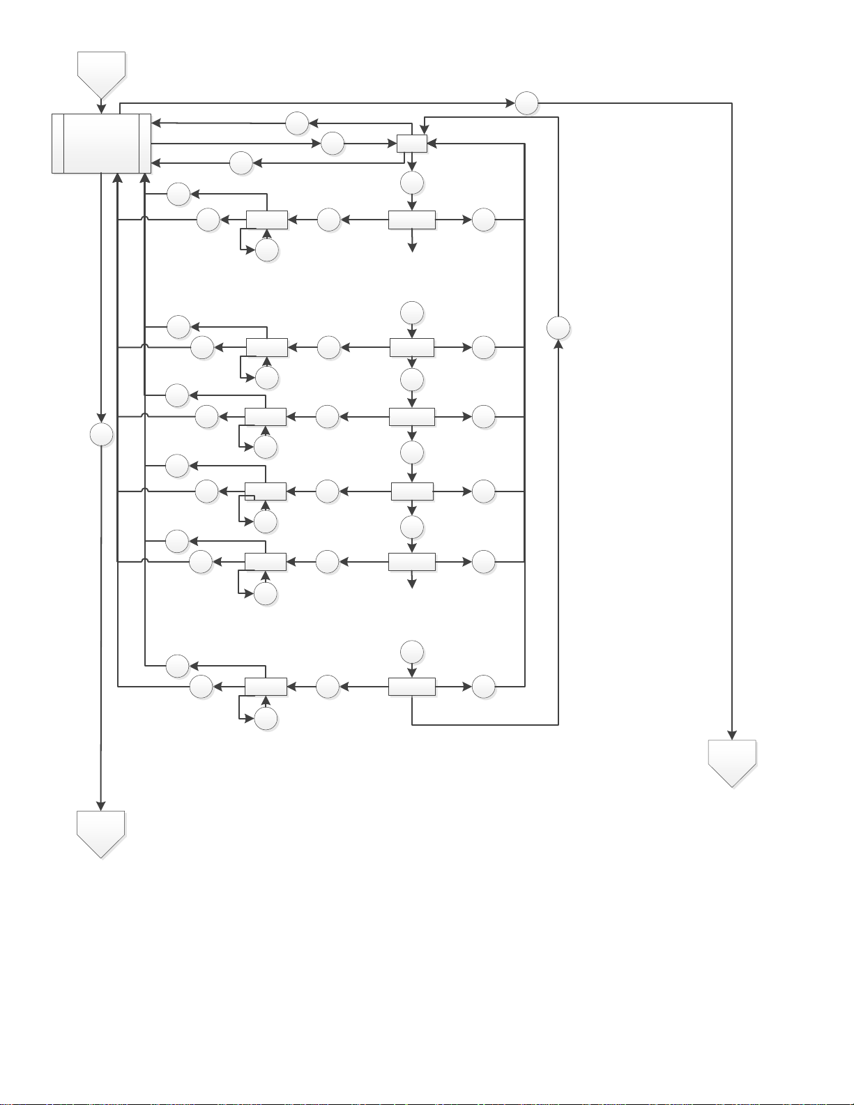
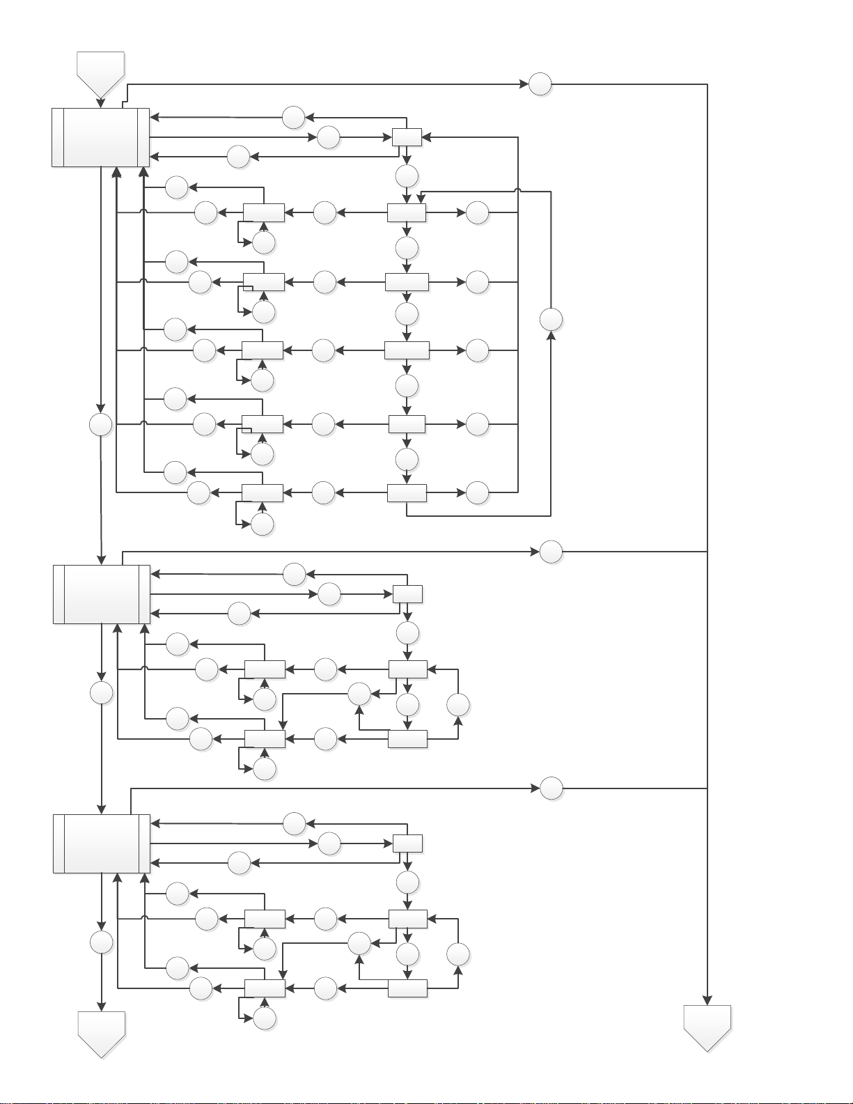
Page 20
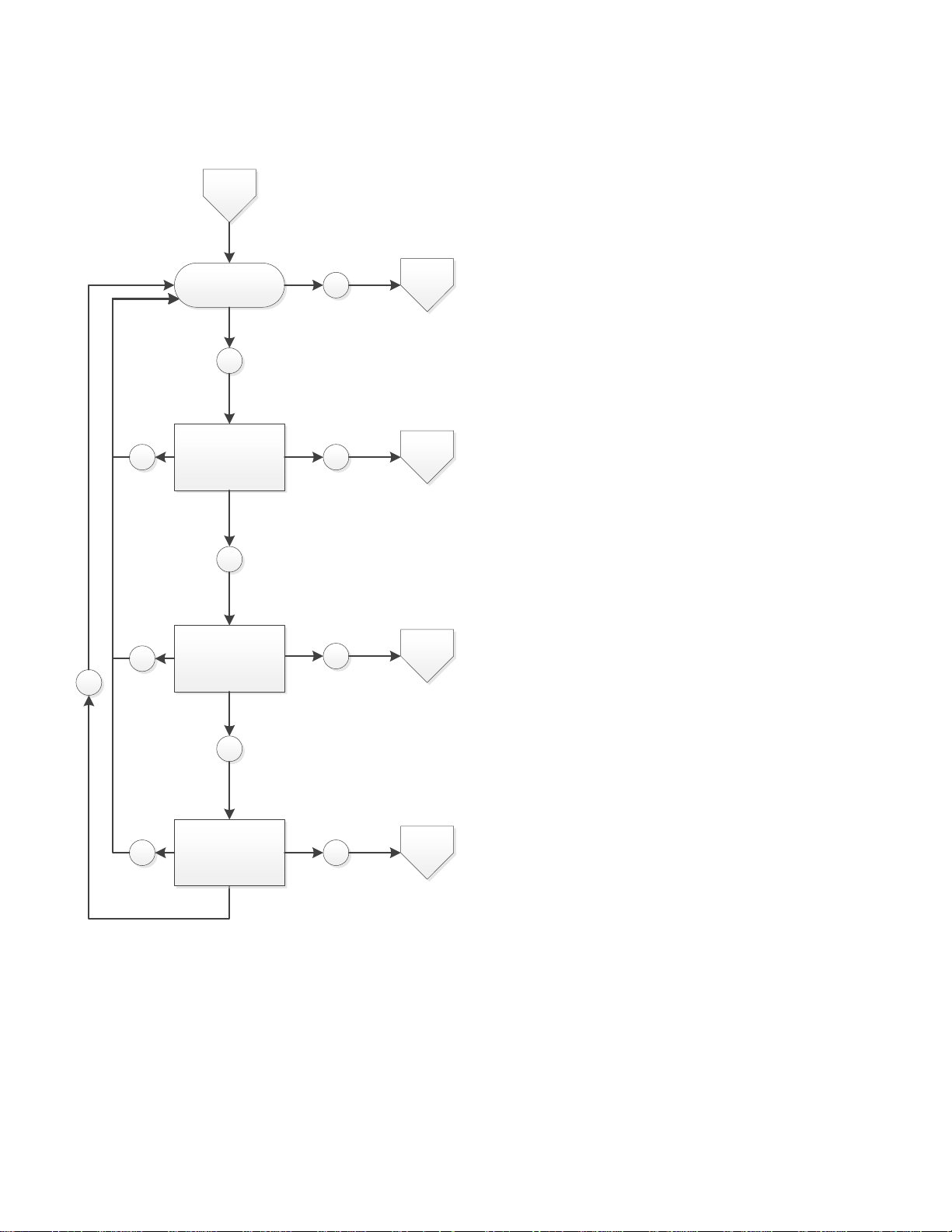
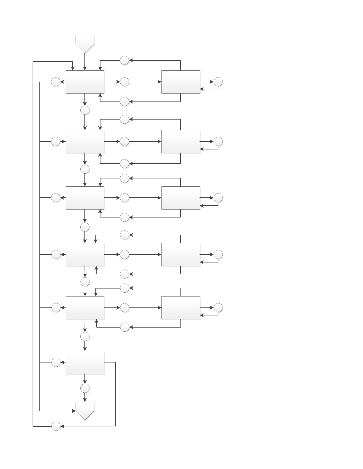
5 Appendix A – Menu Structure
Normal Mode
“Con”
Configuration Mode
E/T
M /N
“tst”
Test Mo de
M /N
M /N
E/T
M /N
E/T
“CAL”
Calibration
(CD6MC only)
bUZ
CAL
E/T
Config 1
tst
Normal
Wait
Wait
Wait
5.1 Main Menu
20
Page 21
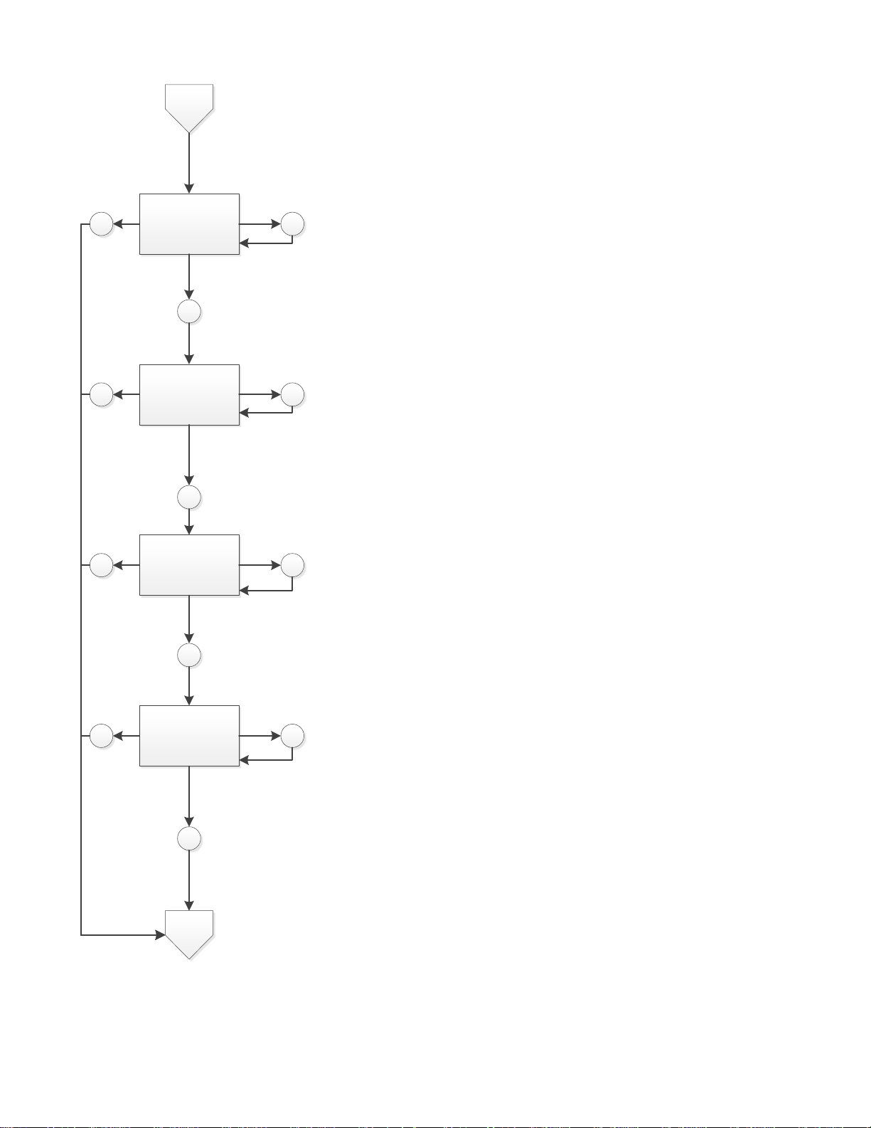
5.2 Auto Test Menu “bUZ”
bUZ
“bUZ”
Buz zer t est
“Art”
Alar m re lay t est
“Frt”
Fa n rel ay tes t
“420”
Current loop test
Normal
M /N E/T
M /N
Wait
E/T
M /N
Wait
E/T
M /N
Wait
E/T
Wait
21
Page 22
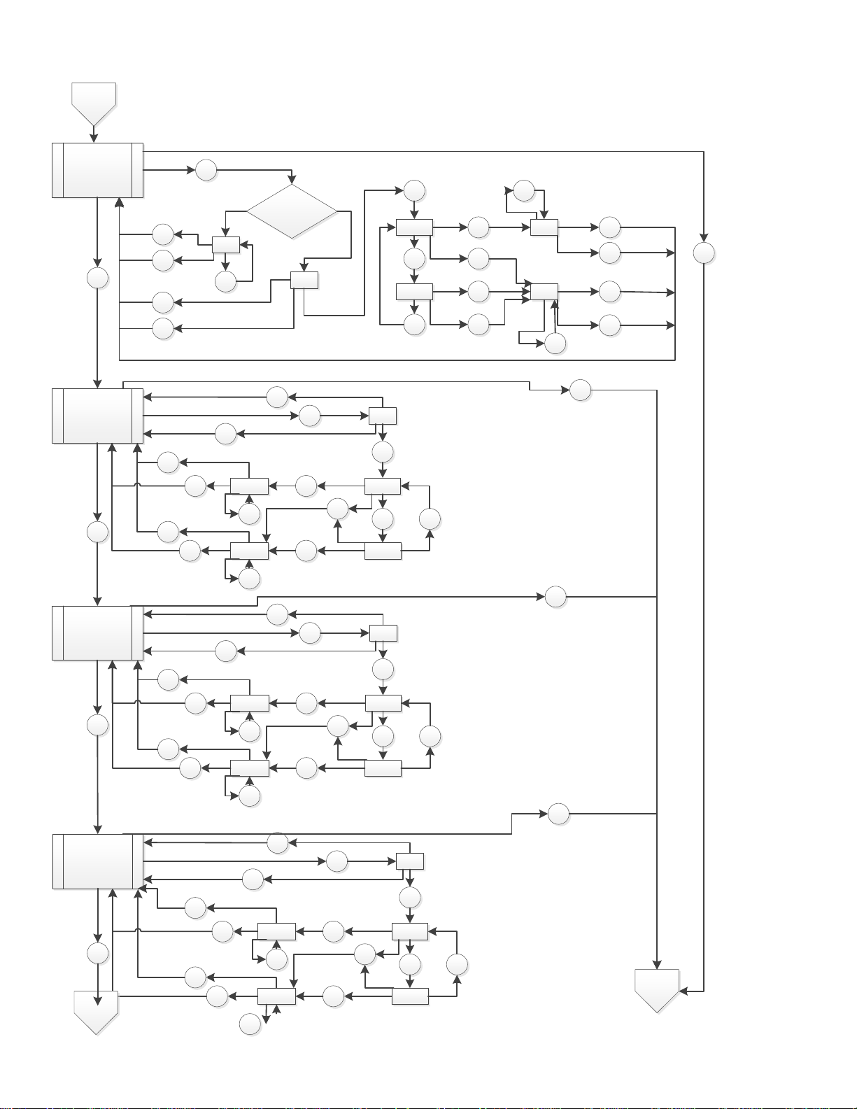
5.3 Configuration M e n u “ CON ”
“dEF”
Default
“Put”
Power up test
“dSP”
Display mode
Deafult
value s?
“YES”
“_nO”
E/T
M /N
Wait
M /N
E/T
M /N
E/T
M /N
Wait
E/T
M /N
Wait
E/T
M /N
WaitE/T
M /N
Wait
“_no”
“YES”“ /YES”
“ / _nO”
E/T
Wait
M /N
Config 1
“_On”
“ / oFF”
“ / _On”
“oFF”
“_On”
E/T
M /N
Wait
E/T
M /N
Wait
E/T
M /N
Wait
E/T
M /N
M /N
E/T
E/T
Go to current setting – ON i n
this example
Wait
“_On”
“ / oFF”
“ / _On”
“oFF”
“_On”
E/T
M /N
Wait
E/T
M /N
Wait
E/T
M /N
Wait
E/T
M /N
M /N
E/T
E/T
Go to current setting – ON i n
this example
Wait
“bUZ”
Buzzer mode
“_On”
“ / oFF”
“ / _On”
“oFF”
“_On”
E/T
M /N
Wait
E/T
M /N
Wait
E/T
M /N
Wait
E/T
M /N
M /N
E/T
E/T
Go to current setting – ON i n
this example
Wait
M /N
Config 2
M /N
Normal
Wait
Wait
Wait
Wait
22
Page 23
Config 2
ArS
Alarm Relay
Setting
“4000”
“ / 4100”
“ / 5000”
“4100”
“5000”
E/T
M /N
Wait
E/T
M /N
Wait
E/T
M /N
Wait
E/T
M /N
M /N
E/T
E/T
Go to current setting – 4000
in this exa mple
Wait
M /N
“ / _900”
“ / 1000”
“_900”
“1000”
E/T
Wait
E/T
M /N
Wait
M /N
M /N
E/T
E/T Wait
“ / _diS”“diS”
E/T
M /N
Wait
M /N
M /N
E/T Wait
Wait
Wait
Config 3
Normal
Wait
“ / 3900”“3900
E/T
M /N
Wait
M /N
E/T Wait
8 more options: 4200, 4300,
…..4900
28 more options: 1100, 1200,
…..3800
23
Page 24
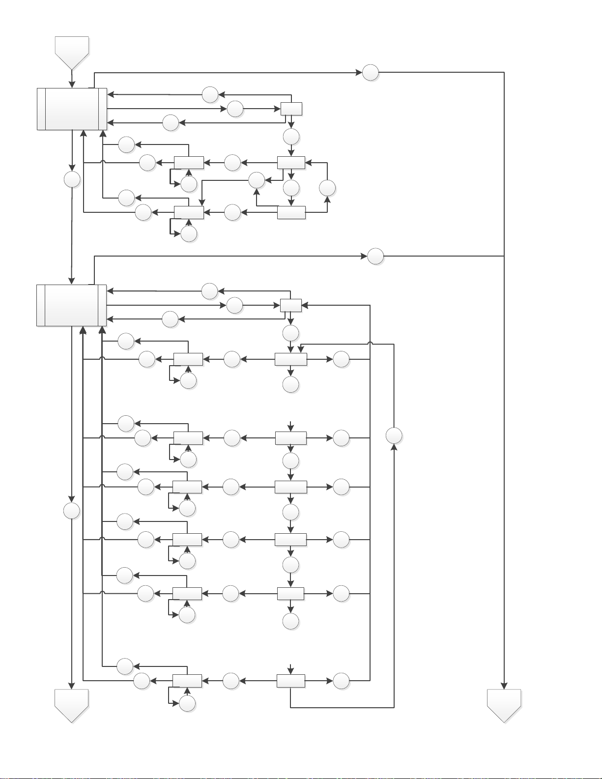
Config 3
“Arc”
Alar m re lay
configuration
“_nO”
“ / _nC”
“ / _nO”
“_nC”
“_nO”
E/T
M /N
Wait
E/T
M /N
Wait
E/T
M /N
Wait
E/T
M /N
M /N
E/T
E/T
Go to current setting – nO in
this example
Wait
M /N
“FrS”
Fan Relay
Setting
“2000”
“ / 2100”
“ / 5000”
“2100”
“5000”
E/T
M /N
Wait
E/T
M /N
Wait
E/T
M /N
Wait
E/T
M /N
M /N
E/T
E/T
Go to current setting – 2000
in this exa mple
Wait
M /N
“ / _600”
“ /2000
“_600”
“2000”
E/T
Wait
E/T
M /N
Wait
M /N
M /N
E/T
E/T Wait
“ /_diS”
“_di S”
E/T
M /N
Wait
M /N
M /N
E/T
Wait
Wait
Wait
“ /_700”“_700”
E/T
Wait
M /N
M /N
E/T Wa it
Config 4 Normal
Wait
Wait
38 more options: 2200, 2300,
…...4800, 4900
12 more options: 800,
900…….1800, 1900
24
Page 25
Config 4
“Frd”
Fan relay delay
“__3”
“ / _5”
“ /_ 10”
“__5”
“__10”
E/T
M /N
Wait
E/T
M /N
Wait
E/T
M /N
Wait
E/T
M /N
M /N
E/T
E/T
Go to current setting – 3 in
this example
Wait
M /N
“ / _1”
“ / _3”
“__1”
“__3”
E/T
Wait
E/T
M /N
Wait
M /N
M /N
E/T
E/T W ait
“ / _0”
“__0”
E/T
M /N
Wait
M /N
M /N
E/T W ait
Wait
Wait
Config 5
Normal
Wait
25
Page 26
Config 5
“Frr”
Fa n rel ay
runtime
“__0”
“ / _3”
“ / _5”
“__3”
“__5”
E/T
M /N
Wait
E/T
M /N
Wait
E/T
M /N
Wait
E/T
M /N
M /N
E/T
E/T
Go to current setting – 0 in
this example
Wait
M /N
“ /_ 15”
“ / _0”
“_15”
“__0”
E/T
Wait
E/T
M /N
Wait
M /N
M /N
E/T
E/T Wait
“ /_ 10”“_10”
E/T
M /N
Wait
M /N
M /N
E/T Wait
Wait
Wait
“FrL”
Fan relay la tch
“OFF ”
“ / _On ”
“ / OFF ”
“_On”
“_O FF”
E/T
M /N
Wait
E/T
M /N
Wait
E/T
M /N
Wait
E/T
M /N
M /N
E/T
E/T
Go to current setting – OFF in
this example
Wait
M /N
“tF S”
Trouble fault
setting
“OFF ”
“ / _On ”
“ / _OF F”
“_On”
“_O FF”
E/T
M /N
Wait
E/T
M /N
Wait
E/T
M /N
Wait
E/T
M /N
M /N
E/T
E/T
Go to current setting – OFF in
this example
Wait
M /N
Config 6
Wait
Wait
Wait
Normal
26
Page 27

Config 6
“420”
Current loop
“_On”
“ / OFF ”
“ / _On
”
“_O FF
”
“_On”
E/T
M /N
Wait
E/T
M /N
Wait
E/T
M /N
Wait
E/T
M /N
M /N
E/T
E/T
Go to current setting – On in
this example
Wait
M /N
“End”
Normal
M /N
E/T
Wait
Config 1
Wait
27
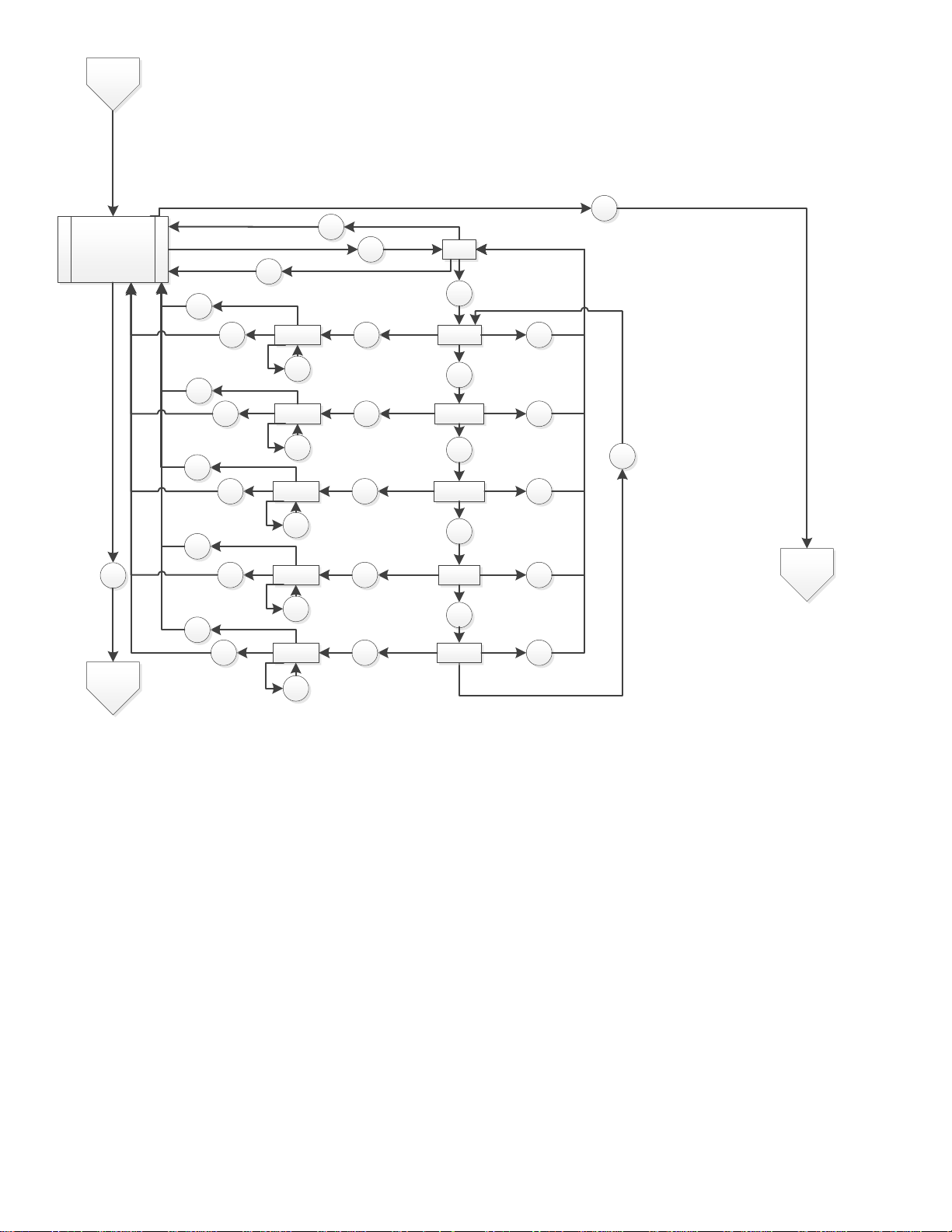
Page 28
5.4 Select Test Menu “tst”
tst
“bUZ”
Buz zer t est
“Art ”
Alar m relay test
“Frt”
Fa n rela y t est
“420”
Current loop test
Normal
M /N
E/T
M /N
E/T
M /N
Wait
E/T
M /N
Wait
E/T
Wait
Wait
“End”
E/T
“___/bUZ”
Buz zer t est
“___/Art”
Alar m relay test
“___/Frt”
Fa n rela y t est
“___/420”
Current loop test
Wait
M /N
M /N
E/T
120
M /N
E/T
60
M /N
E/T
10
M /N
E/T
10
“gSt”
Gas te st
E/T
M /N
Wait
“___/gSt”
Gas te st
M /N
180
E/T
28
Page 29

5.5 CAL Menu * CD-12MC Only
CAL
“400”
Cal mode
(CD6MC only)
“End”
“400/___”
Waiting for gas
Gas OK within
90 secs?
“GR/CAL"
Gas reading
alt ernates wi th CAL
until stable (165 s)
Cal OK?
“GR/FAil” alternate
gas reading with
FAil
“GR /PAS” gas
reading alternating
with PAS
NO
YES
NO YES
E/T
E/T
E/T
M /N
M /N
Normal
E/T
29
Page 30

6 MACURCO PRODUCTS LIMITED WARRANTY
Macurco warrants the CD-12H / CD-12MC gas detector will be free from defective materials and workmanship for a period of two (2)
years from the date of manufacture (indicated on the inside cover of the CD-12H / CD-12MC), provided it is maintained and used in
accordance with Macurco instructions and/or recommendations. If any component becomes defective during the warranty period, it will
be replaced or repaired free of charge, if the unit is returned in accordance with the instructions below. This warranty does not apply to
units that have been altered or ha d r e pair attem pted, or tha t have been sub jecte d to abu se, acc identa l or other wi se. T he a bove w arra nty
is in lieu of all other express warranties, obligations or liabilities. THE IMPLIED WARRANTIES OF MERCHANTABILITY AND FITNESS
FOR PARTICULAR PURPOS E ARE LIMIT ED TO A PERIO D OF TWO (2 ) YEARS FROM T HE PURCHASE DATE. Macurc o shall n ot
be liable for any inc idental or consequ ential da mages for bre ach of t his or any other warra nty, expr ess or implied, ar ising out of or re lated
to the use of said gas detect or. The manufacturer or its agent’ s liability shall be limited to replaceme nt or repair as set forth above. Buyer ’s
sole and exclusive rem ed ie s a re the return of the good s an d repaym ent of t he pri ce, or r epa ir and rep lac ement of no n-conf orming goods
or parts.
Macurco Gas Detection
3601 N. St. Paul Avenue
Sioux Falls, SD 57104
Technical Support Contact Information
Phone: 844-325-3050
Email: support@macurco.com
Website: www.support.macurco.com
General Contact Information
Phone: 877-367-7891
Fax : 512-524-3415
Email : info@macurco.com
Website: www.macurco.com
Rev. A
Issue Date: 03-09-2018
Document No: 34-2900-0132-7
© Aerionics 2018. All rights reserved.
Macurco is a trademark of Aerionics, Inc.
30
Page 31

Macurco™ CD-12H / CD-12MC
Détecteur d e Dio xyd e de C arbo n e, Con t rô leur et
Transducteur Instructions d'utilisation
Important: Conservez ces instruc tions d'utilisation pour référence
Page 32

Table of Contents
1 INFORMATIONS GÉNÉRALES DE SÉCURITÉ ......................................................................................................................... 3
1.1 Utilisation prévue ........................................................................................................................................................................ 3
1.2 Liste des avertissements et mises en garde dans ce manuel d'utilisation ................................................................................. 3
2 INSTRUCTIONS ET LIMITES D'UTILISATION ........................................................................................................................... 4
2.1 Utilisations .................................................................................................................................................................................. 4
2.2 Utilisations à éviter ..................................................................................................................................................................... 4
2.3 Description générale .................................................................................................................................................................. 4
2.4 Généralités, ................................................................................................................................................................................ 5
2.5 Caractéristiques ......................................................................................................................................................................... 5
3 INSTRUCTONS D’INSTALLATION ET D'UTILISATION ............................................................................................................. 6
3.1 Emplacement ............................................................................................................................................................................. 6
3.2 Informations générales de câblage ............................................................................................................................................ 6
3.3 Raccordement de l’alimentation principal ................................................................................................................................... 6
3.4 Raccordement du relais de ventilateur ....................................................................................................................................... 6
3.5 Raccordement du relais d'alarme ............................................................................................................................................... 7
3.6 Raccordement du signal 4-20 mA .............................................................................................................................................. 7
3.7 Installation .................................................................................................................................................................................. 7
3.8
M
ettre en marche ..................................................................................................................................................................... 11
3.9 Opération ................................................................................................................................................................................. 11
3.10 Configuration par défaut - Paramètres usine............................................................................................................................ 11
3.10.1 Sélection configuration par défaut - "dEF" ................................................................................................ 12
3.10.2 Sélection d’option de démarrage Test - "PUt" ........................................................................................... 12
3.10.3 Sélection d’option d'affichage - "dSP" ....................................................................................................... 12
3.10.4 Sélection d’option alarme - "bUZ" ............................................................................................................. 12
3.10.5 Sélection réglage du relais d'alarme – "ArS" ............................................................................................. 13
3.10.6 Sélection de configuration du Relais Alarme - "Arc" ................................................................................. 13
3
.10.7 Sélection des paramètres de relais ventilateur - "FrS" .............................................................................. 13
3.10.8 Sélection de relais ventilateur retardé - "Frd" ............................................................................................ 13
3.10.9 Sélection relais de ventilateur d'exécution - "Frr" ...................................................................................... 13
3.10.10 Sélection de relais de ventilateur, option de verrouillage - "FrL" ............................................................... 13
3.10.11 Sélection de ventilateur de condition de trouble option - "tFS" ................................................................. 14
3.10.12 Sélection 4-20mA Option de sortie - "420" ................................................................................................ 14
3.11 Systèmes de diagnostic ........................................................................................................................................................... 14
4 Entretien .................................................................................................................................................................................... 15
4.1 Signal de fin de vie
................................
................................................................................................................................... 15
4.2 Nettoyage ................................................................................................................................................................................. 15
4.3 Essai 15
4.3.1 Test de fonctionnement ............................................................................................................................ 16
4.3.2 Test manuel d'opération ............................................................................................................................ 16
4.3.3 Test de dioxyde de carbone ...................................................................................................................... 17
4.4 Test de gaz .............................................................................................................................................................................. 17
4.4.1 Test du relais de ventilateur ...................................................................................................................... 17
4.4.2 Test du relais d'alarme .............................................................................................................................. 18
4.4.3 Testing the 4-20mA current loop ............................................................................................................... 19
4.4.4 Calibration manuelle – CD-12MC UNIQUEMENT .................................................................................... 19
5 Annexe A – Structure de menu .................................................................................................................................................. 21
5.1 Menu principal .......................................................................................................................................................................... 21
5.2 Menu Auto Test “bUZ” .............................................................................................................................................................. 22
5.3 Configuration du Menu “CON” .................................................................................................................................................. 23
5.4 Choix du Test Menu “tst” .......................................................................................................................................................... 29
5.5 Menu CAL * CD-12MC uniquement ......................................................................................................................................... 30
6 GARANTIE LIMITÉE DES PRODUITS MACURCO .................................................................................................................. 31
Technical Support Contact Information ............................................................................................................................................. 31
eneral Contact Information
G
................................
............................................................................................................................. 31
2
Page 33

AVERTISSEMENT
1 INFORMATIONS GÉNÉRALES DE SÉCURITÉ
1.1 Utilisation prévue
Le Macurco CD-12H et CD-12MC est un détecteur de dioxyde de carbone (CO2) à tension de ligne, contrôleur, et transducteur avec
deux relais. Le CD- 12« x » posséde des opt ions d’ un sortie 4-2 0 mA, un sondeur et de s op tions d'aff ichage n umérique sélectionna ble.
Il s'agit d'un système de détection électronique utilisé pour mesurer la concentration de dioxyde de carbone et fournir de la rétroaction
et de contrôle automatique du ventilateur d'écha ppement pour aider à réduire les concentra tions de C O
salles de classe, salles de réunion ou des applications similaires. Le CD-12« x » est un compteur de bas niveau capable d'afficher de
0 à 5000 ppm (parties par million) de dioxyde de carbone. Le CD-12« x » est étalonné en usine et testés à 100% pour un bon
fonctionnement.
Le dispositif de détection de série CD-12H emploie un programme de calibration en arrière-plan, qui va procéder régulièrement à
l'ajustement du niveau d'air pur.
Le détecteur CD-12MC possède des fo nctions et des réglages identiques à ceux du CD-12H, hor mis qu'il propose égalemen t une fonction
de calibration manuelle. Le CD-12MC nécessite une calibr ation man uelle à l'aide du k it de c alibration C D6-FCK au minimum une fois par
an.
1.2 Liste des avertissements et mises en garde dans ce manuel d'utilisati on
dans les salles de conféren ce,
2
• Chaque personne utilisant cet apareil doit lire et comprendre les informations contenues dans ces instructions d'utilisation avant
de l'utiliser. L'utilisation de cet appareil par des personnes non qualifiées, ou de l'utilisation qui n'est pas en conformité avec ces
instructions d'utilisation, peuvent nuire la performance du produit en résultant en cas de maladie ou de décès.
• Utilisez uniquement pour surveiller le gaz que le capteur et l'instrument sont conçus pour surveiller. Ne pas le faire peut entraîner
des expositions aux gaz non détectable qui peuvent causer des maladies ou la mort. Pour une utilisation correcte, voir votre
superviseur, lire les instructions d'utilisation et/ou appeler au service technique au 1-844-325-3050.
• Cet appareil ne peut fonctionner d’une manière efficace en dessous de 32° F ou au-dessus de 122 ° F (0° C ou au-dessus de 50°
C). Utilisation du détecteur à l'extérieur de ces températures peut affecter les performances du produit et entraîner des maladies
ou la mort.
• Ce détecteur permet de surveiller la présence et le niveau de concentration d'un certain gaz dans l'air déterminé. Usage impropre
peut produire une lecture inexacte, ce qui signifie que des niveaux plus élevés de gaz à surveiller peuvent être présents et
pourraient entraîner une surexposition et la cause de maladie ou de décès. Pour une utilisation correcte, voir votre superviseur,
lire les instructions d'utilisation et/ou appeler au service technique au 1-844-325-3050.
• Bornes de relais à haute tension (120/240 VAC) sont situés dans ce détecteur, présentant un danger pour les techniciens de
service.
• Seulement des techniciens qualifiés devraient ouvrir le boîtier du détecteur et entretenir les circuits internes. Assurer que la
puissance est retirée des relais du détecteur avant l'entretien de l'unité. Ne pas le faire peut entraîner des maladies ou la mort .
• Ne démontez pas l'unité, ni essayer de réparer ou de modifier les composants de cet instrument. Cet instrument ne contient aucune
pièce réparable, et la substitution de composants peut nuire à la performance du produit et entraîner des maladies ou la mort.
• L'utilisation d'un gaz certifié avec une concentration différente de celle indiquée pour ce détecteur lorsque vous effectuez un test
d'étalonnage (test de déclenchement) va produire des lectures inexactes. Cela signifie que les niveaux plus élevés de gaz à
surveiller peuvent être présente et pourrait entraîner une surexposition et la cause de maladie ou de décès. Pour une utilisa tion
correcte, voir votre superviseur, lire les instructions d'utilisation et/ou appeler au service technique au 1-844-325-3050.
• Les étapes suivantes doivent être effectuées lors de la conduite d'un vérification de l'étalonnage (bump te st) pour assurer la bonne
performance de l'appareil. Ne pas le faire pourrait nuire à la performance du produit et entraîner des maladies ou la mort. Lors
d'un vérification de l'étalonnage, utiliser seulment du gaz d'étalonnage certifié avec le niveau de concentration nécessaire.
o Ne pas un test d'étalonnage avec un gaz d'étalonnage expiré.
o Ne pas couvrir ou obstruer l’affichage ou la couverture d'alarme visuelle.
o S'assurer entrées de capteurs est dégagées et sont exempts de débris
3
Page 34

2 INSTRUCTIONS ET LIMITES D'UTILISATION
AVERTISSEMENT
AVERTISSEMENT
AVERTISSEMENT
Chaque personne utilisant cet équipement doit lire et comprendre les informations contenues da ns ces instructions d'utilisation avant de l'utiliser.
L'utilisation de cet appareil par des personnes non qualifiées ou non qualifiées, ou de l'utilisation qui n'est pas en conformité avec ces
instructions d'utilisation, peuvent nuire la performance du produit et le résultat en cas de maladie ou de décès.
2.1 Utilisations
Le CD-12« x » fournit une détection de CO2 et le contrôle automatique de ventilation pour salles de conférence, salles de classe, salles de
réunion ou des applications similaires. Le dioxyde de carbone est un gaz incolore et inodore qui est produite à la fois par des personnes
exhalant CO
de 350-450 parties par million (ppm) ou plus dans des zones où la circulation des véhicules ou de grande activité industrielle. Le niveau de
CO
intérieur dépend du nombre de personnes présentes, combien de temps une zone a été occupée, la quantité d'air frais entrant dans la
2
zone et d'autres facteurs. Les concentrations de dioxyde de carbone à l'intérieur peuvent varier de plusieurs centaines de parties par million à
plus de 1000 ppm dans les zones avec beaucoup de personnes présentes pendant une période prolongée et où la ventilation d'air frais est
limitée. Ventilation extérieure "frais" de l'air est importante car elle peut diluer CO
être fournie à une pièce dépend du type d'installation et la salle. La ventilation doit maintenir les concentrations de dioxyde de carbone en
dessous de 1000 ppm et de créer des conditions intérieures de qualité de l'air qui sont acceptables pour la plupart des individus.
Pour des installations de stockage ou employant des cuves de CO
peuvent notamment, mais non exclusivement, inclure : des installations de stockage alime ntaire, de distribution de boissons, agri coles, de lutte
contre les incendies, médicales, etc.
Le dispositif de détection de série CD-12H emploie un programme de calibration en arrière-plan, qui va procéder régulièrement à l'ajustement
du niveau d'air pur. Le CD-12H maintiendra u n haut niveau de p récision s'il est exposé, au moin s une fois par s emaine, à la « concentration de
référence en air pur » (qui correspond à la concentration en gaz détecté la plus basse à laquelle le dispositif est soumis).
Le CD6-MC n'effectue aucune calibration automatique en arrière-plan. Il est donc recommandé de réaliser une calibration manuelle au moins
une fois par an à l'aide du kit de calibration Macurco CD6-FCK.
Remarque: Ceci s'applique l orsqu'il est utilisé dans l'air a mbiant intérieur typique. Le CD-12 "x" peut être utilisé comm e un détecteur autonome.
À utiliser avec le panneau de commande de détection et de ventilation Macurco (DVP-120 uniquement) et d'autres panneaux d'incendie / de
sécurité ou d'automatisation de bâtiments. La tension de ligne est fournie au CD-12 "x" et la boucle de communication 4-20 mA raccordé au
panneau.
ainsi la combustion de l'essence, le charbon, le pétrole et le bois. La concentration extérieure de dioxyde de carbone peut varier
2
de l'environnement intérieur. La qua ntité d'air frais qui devrait
2
, le détecteur enverra une alerte en cas de fuite de gaz. Ces installations
2
Utilisez uniquement pour surveiller le gaz que l e capteur et l'instrument sont conçus pour surveill er. Ne pas le faire pe ut entraîner une expos ition
aux gazes de serre non détectable qui peut causer la maladie ou la mort. . Pour une utilisation correcte, voir votre superviseur, lire les
instructions d'utilisation et/ou appeler le Service technique au 1-844-325-3050.
2.2 Utilisations à éviter
Le CD-12« x » n'est pas destiné à être utilisé dans d es zones da ngereuses ou des applications i ndustrielles telles qu e les raffineries, les usines
chimiques, etc. Ne pas monter le CD-12« x » où la température ambiante normale est inférieure à 32° F ou supérieure à 122° F (0° C ou audessus de 50° C). Le CD-12« x » se monte sur un boîtier électrique 4S, fourni par l'entrepreneur. Ne pas i nstaller l e CD-12« x » dans un autre
boîtier sauf s’il y a une bonne circulation de l'air.
Cet appareil ne peut fonctionner de manière efficace en des sou s de 32° F ou sup érieure à 122° F (0° C ou au -dessus de 50° C). Utilisation du
détecteur à l'extérieur de ces températures peut affecter les per formances du p roduit et entraîner des maladies ou la mort.
2.3 Description générale
Le Macurco CD-12H est un détecteur de dioxyde de carbone (CO2) à basse tension et contrôleur de la ventilation automatique. Le CD12« x » utilise un système electronique de contrôle micro-ordinateur pour mesurer la concentration de CO
une sortie 4-20 mA. Le CD-12« x » a une longue durée de vie à faible entretien (15+ ans) infrarouge (NDIR) capteur non dispersif et des kits
de test de gaz en option. Le CD-12« x » est un indicateur de niveau bas capable d'afficher de 0 à 5000 ppm de à partir de dioxyde de
carbone.
4
, actionner les relais et de fournir
2
Page 35

2.4 Généralités,
• ETL LISTED to UL 61010-1, Certified to CAN/CSA Std. C22.2 No 61010-1
• Compteur de bas niveau capable d'afficher 0-5000 ppm de CO
• Capteur de résolution 50 PPM
• Le CD-12H utilise un programme d'étalonnage de fond automatisé pour définir le niveau de qualité de l'air sur une base régulière*
• Le CD-12MC utilize une calibration manuelle pour obtenir des niveaux d’air prope en utilisant un kit de calibration**
• Ventilateur de sélection et acti vation du relais d'alarme
• Inverseur ventilateur relais de 5 A avec commande entrées de ventilateurs d'extraction
• Le relais d'alarme NO ou NF de 0.5 A se connecte à des dispositifs d'avertissement ou des panneaux de contrôle
• 4-20 mA boucle de courant
• CD-12 se monte sur un boîtier électrique standard de 4x4 et devient couvercle du boîtier
• Système de surveillance: un problème de détecteur interne fera activer le ventilateur et le relais d'alarme
• Kit de test de vérification de l'étalonnage est disponible. Une vis permet un accès pour le test de gaz
• Le capteur de dioxyde de carbone possède une durée de vie nominale de 15 ans. L'alarme de fin de vie se déclenche après
une durée d'utilisation du capteur de 180 mois.
• Le kit de test de vérification de la calibration de l'appareil est disponible. Un tour de vis permet d'accéder au test de présence
d'un gaz
*CD-12H uniquement
**CD-12MC uniquement
2
2.5 Caractéristiques
•
Tension: 100 - 240VAC (50 – 60 HZ)
• Courant: 1.0 A MAX
• Poids: 1 livre (0,45 kg)
• Taille: 4 1/2 x 4 x 2 1/8 po (11,4 X 11,4 X 5,3 cm)
•
Couleur: Blanc ou gris foncé
• Connexions: fiches / bornes
•
Boîte de montage: (non inclus) 4x4 électrique
• Relais du ventilateur: 5 A, 240 VAC, le devoir de pilote, SPDT, verrouillage ou non-verrouillage
•
Ventilateur relais actionnement: sélectionnable à diS (désactiver), 600, 700, 800, 900, 1000 (par défaut)…, 4800, 4900,
5000 ppm
•
Paramètres de délai Ventilateur de 0, 1, 3 (par défaut), 5 et 10 minutes
•
Ventilateur paramètres d'exécution minimum sont 0 (par défaut), 3, 5, 10 ou 15 minutes
•
Relais du ventilateur de verrouillage ou non verrouillage (par défaut) sélectionnable
• Relais d'alarme: 0,5 A, 120 V, 60 VA
•
Relais d'alarme actionnement: sélectionnable NO (par défaut) ou NC
•
Paramètres de relais d'alarme: diS (disabled), 900, 1000, 1100, 1200, ... 4000 (par défaut)…, 4900, 5000
•
Boucle de courant 4-20 mA pour 0-5000 ppm de CO2 sélectionnable à arrêt ou marche (par défaut)
•
Alarme: 85 dBA à 10 cm réglable à désactivé (par défaut) ou sur marche
•
Affichage numérique: 4 chiffres LED sélectionnable désactivé (par défaut) ou marche
•
Environnement d'exploitation: 32 ° F à 122 ° F (0 ° C à 50 ° C) 10 à 90% HR
5
Page 36

3 INSTRUCTONS D’INSTALLATION ET D'UTILISATION
AVERTISSEMENT
AVERTISSEMENT
Les instructions suivantes sont destinées à servir de guide pour l'utilisation de la Macurco CD-12H / CD-12MC détecteur de dioxyde de
carbone. Il ne s'agit pa s d'être considér ée co mme ex haustif, et il n'est pas de stiné à rem placer la politique et les proc édures po ur chaque
installation. Si vous avez des d outes quan t à l'appl icabilité de l'équipe ment à votr e situat ion, consultez un h ygiéniste indust riel ou service
technique au 1-844-325-3050
Ce détecteur permet de surveiller la présence et le niveau de concentration d'un certain gaz dans l'air déterminé. Une mauvaise utilisation peu t
produire une lecture inexacte, ce qui signifie que des niveaux plus élevés de gaz à surveiller peuvent être présents et pourraient entraîner une
surexposition et provoquer des maladies ou la mort. Pour une utilisation correcte, voir superviseur ou les instructions d'utilisation ou appeler
le service technique au 1-844-325-3050.
3.1 Emplacement
La hauteur de fixation du dispositif dépen d du type d'installa tion équ ipé. Po ur des in stallatio ns compren ant des cuves de CO2, la hauteur
de fixation minimale doit être d'environ 1 pied au dessus du sol (soit environ 30 cm). Pour une mesure précise de qualité de l'air en
environnement fermé, fixer le détecteur au niveau de ventilation optimal, à savoir environ 5 pieds (1,5 m) au dessus du sol sur un mur
ou une colonne au centre d'une pièce, où la circulation de l'air est bonne. L'équipement est capable de couvrir une surface d'environ
5000 pieds carrés. (soit environ 465 mètres carrés). Les performances de l'équipement dépendent de la qualité de circulation de l'air au
sein de la pièce ou de l'entrep ôt. D es dis positifs su pplé ment aires peuv ent être n éce ssa ires à pro xim ité d es zon es de tr av ail o u da ns de s
zones dans lequel la circul atio n d'air stagn e. Le s disp osit ifs d e séri e CD-12 « x » sont fixés à un coffret électrique, fourni par le fabricant.
Merci de ne pas procéder à l'installa tion du d ispositif de sér ie CD-12 « x » d ans un a utre coff ret, sau f si la vent ilation à l'inté rieur de cel uici est optimale. Merci de ne PAS INSTALLER le dispositif de série CD-12 « x » dans des mili eux où la température ambiante est inférie ure
à 32° F ou supérieure à 122° F (inférieure à 0° C ou supérieure à 50° C).
.
Bornes de relais haute tension (120/240 VAC) sont situés dans ce détecteur, présentant un danger pour les techniciens de maintenance.
Seul un technicien qualifié techniciens doit ouvrir le boîtier du détecteur pour le service des circuits internes. Assurer que la puissance est
retirée des relais de détection avant l’entretien de l'appareil. Ne pas le faire peut e ntraîner des maladies ou la mort.
3.2 Informations générales de câb lage
À l'exception de la mise à la terr e de séc urité, t ous l es c âblag es sur site s ont co mpl étés via des connect eur s modul aires (f our nis). Apr è s
avoir effectué le câblage, branchez simple ment les connecte urs modulaires dan s les conne cteurs correspondants à l'arrière du détecteur.
3.3 Raccordement de l’alimentation princ ipa l
Les raccordements électriques doivent être effectuées conformément aux codes électriques nationaux et locaux. Seul le personnel
qualifié doit raccorder l'alimentation électrique secteur à tout appareil. Macurco recommande un fil de calibre minimum AWG18 et
l'isolateur de fil doit être conçu pour fonctionner à 140 ° F (60 ° C). Le connecteur modulaire acceptera le fil de grosseur 12 à 24 AWG.
Le fil de mise à la terre de sécurité doit être fixé à la vis de mise à la terre de la boîte électrique en métal. Serrez la vis et assurez-vous
que le fil est bien serré. Assurez-vous que le fil ne peut pas être retiré. Les fils de ligne Line (L) et le neutre Neutral (N) doivent être
dénudés de 6,5 mm (1/4 in.), Insérer le fil "L" et "N" du connecteur modulaire Fan / Power et serrer le collier de serrage. Assurez-vous
que le fil ne peut pas être facilement retiré tiré du connecteur. Branchez la connexion modulaire dans la connexion ventilateur /
alimentation et assurez-vous qu'elle se verrouille correctement.
3.4 Raccordement du relais de ventil at eur
Toutes les bornes du relais du ventilateur SPDT sont disponibles sur le connecteur modulaire Fan / Power. Chaque borne de relais de
ventilateur normalement ouvert, commun et normalement fermée (NO, COM et NC) peut recevoir un fil de calibre 12 à 24 AWG. Pour
installer le câblage pour le des relais, dé connecte z les connecteurs de l'en-tête. D énudez l' isolant de chaq ue fil d'en viron ¼ po (6, 5 mm),
insérez le fil dénudé dans la borne et serrez la vis. Assurez-vous que le fil ne peut pas être facilement retiré du connecteur. Branchez la
connexion modulaire dans la connexion ventilateur / alimentation et assurez-vous qu'elle se verrouille correctement dans l'en-tête.
6
Page 37

3.5 Raccordement du relais d'alarme
Les raccordements d'alarme externes (A et B) sont disponibles sur le connecteur modulaire Alarme. Il n'y a pas de polarité pour ces
raccordements. Pour installer le câblage des contacts d'alarme, déconnectez le connecteur de l'en-tête du détecteur. Dénudez l'isolant
de chaque fil d'environ 6,5 mm (1/4 po), insére z le fil nu dans la borne et serrez la vis. Assur ez-vous que le fil ne p eut pas être facilem ent
retiré du connecteur. Lorsque les fils sont connectés, placez le connecteur modulaire dans le collecteur en vous assurant que le verrou
s'enclenche.
3.6 Raccordement du signal 4-20 mA
Les Raccordements de signaux 4-20 mA positives et négatives (+ et -) sont disponibles sur le connecteur modulaire 4-20 mA, un
connecteur à 2 positions. Pour installer le câblage des contacts 4-20 mA, débranchez le connecteur de l'en-tête du détecteur. Dénudez
l'isolant de chaque fil d'environ 6,5 mm (1/4 po), insérez le fil nu dans la borne et serrez le serre-joint. Assurez-vous que le fil ne peut
pas être facilement retiré du connecteur. Lorsque les fils sont branchés, placez le connecteur modulaire dans le collecteur en vous
assurant que le verrou s'enclenche.
Remarque: Les sorties de boucle d e co urant 4-20 mA peuvent être utilisées a vec le p anne au de contr ô le Macurco DVP-120 ou d'autres
systèmes. Les raccordements de signaux 4-20 mA aux détecteurs doivent être de taille AWG18 (minimum) pour les courtes distances.
Reportez-vous au tableau pour les calibres de fil recommandés. Ne pas regrouper les raccordements de signal du détecteur 4-20 mA
avec les câbles d'alimentation AC pour év iter les interfér ences électriq ues. Si les ra ccordements d' alimentation A C doivent être group ées
avec les câbles de signal du détecteur 4-20 mA, les connexions de signal doivent être réalisées avec une paire torsadée de calibre
appropriée, avec un blindage global en feuille et en tresse. Tous les blindages doivent être terminés à l'extrémité du DVP-120
uniquement. Un raccord de mise à la terre de masse est fourni près du coin inférieur gauche du panneau DVP-120.
3.7 Installation
1. Le CD-12« x » se monte sur un carré de 4 po (ou 4x4) boîtier électrique fourni par l'entrepreneur. Ne montez pas le CD12« x » dans un autre boîtier, à moins qu'il ait une bonne circulation de l'air.
2. Connectez le CD-12« x » à l’alimentation classe 2 seulement. Il est recommandé d'utiliser un transformateur séparé pour
alimenter l'unité ou des unités en raison de l'interférence possible à partir d'autres appareils sur la même alimentation.
3. Connectez le CD-12« x » pour les câbles de commande avec borniers. Lors des connexions, assurez-vous que
l'alimentation est coupée.
4. Il ya deux terminaux de puissance: de 12 à 24 VAC ou 12 à 32 VDC, sans préférence de polarité.
5. Il ya deux terminaux pour les contacts d'alarme de relais secs, encore une fois sans préférence de polarité. Le relais d'alarme
peut commuter jusqu'à 0.5 A 120 V, ou 60 VA. Le relais d'alarme est activé si le gaz atteint ou dépasse les paramètres
d'alarme. Pour plus d'informations concernant le réglage des relais, consultez la section 3.4 MISE EN OEUVRE
d'utilisation.
6. Le relais d'alarme peut être configuré à normalement ouverts (par défaut) (NO) ou normalement fermé (NC) et s'active si le
gaz concentration dépasse le point de consigne d’alarme. Il sera désactivé une fois que la concentration de gaz descend en
dessous du point de consigne d'alarme. Notez que le réglage "désactiver" fera le relais d'alarme ne pas s'engager du tout.
7. Le contact sec, SPDT relais de ventilateur dispose de trois terminaux. Le commun (Com.), normalement ouvert (NO) et le
contact normalement fermé (NC). Le relais de ventilateur peut commuter jusqu'à 5.0 A à 240 VAC. Pour plus d'informations
concernant le réglage des relais, consultez la section 3.4 MISE EN OEUVRE de ce manuel d'utilisation.
8. Le relais de ventilateur peut être configuré pour verrouiller ou non-verrouillage (par défaut) lorsqu'il est activé (lorsque la
concentration de gaz dépasse le point de consigne du relais de ventilateur). Une fois verrouillé, l’alimentation devra être
interompue ou le bouton "TEST" appuyé pour non verrouiller la condition de relais.
9. Le relais de ventilateur engagera si le réglage ventilateur concentration de de dioxyde de carbone est dépassé pendant plus
de temps que le retard de relais ventilateur. Sauf s'il est configuré pour verrouiller, le relais de ventilateur dégagera une fois
que ces deux conditions sont remplies:
• La concentration de dioxyde de carbone a chuté en dessous de réglage du ventilateur
• Le retard de relais ventilateur a été dépassé
de ce manuel
7
Page 38

Notez que le réglage du ventilateur "désactiver" fera que le relais du ventilateur ne s’engage pas. Le relais de ventilateur
Dioxyde de Carbone : ppm
Puissance
AC ou DC
Pas de polarité
Ventilateurs
Contrôles
(transformateur et
Dispositio n typique
Monter au centre
Entrée d’air:
Transformateur
Puissance
12/24 V
RELAIS
D’ALARME
SPDT RELAIS DE
VENTILATION
Pour panneau informatique
4-20 mA boucle
Pour alarme à distance 24 V CA
RELAIS 24 V CA
bobine
Ventilateurs
d’extraction
Alim. du ventilateur
ou
s'engagera en condition de défaut (si le ventilateur de condition de malfonction est réglé sur "ON") et s’arrêtera une fois la
condition de problème de défaut est effacée.
10. La boucle de courant est de 4 mA à l'air propre et 4-20 mA pour 0-2000 ppm CO
2
3.7.1 Diagramme pour un courant d'alimentation du relais de commande du ventilateur compris entre 4 et 20 mA
d’extraction
relais)
dans un petit
garage
porte, volet,
amortisseur
de courant
ou le contrôle
bobine
principal
3.7.2 Raccordement de base au réseau électrique d'une pièce
8
Page 39

Puissance
Transformateur
24 VAC
Puissance du
ventilateurs principal
Ventilateur s d’extract ion
AC ou DC
Pas de polarité
AC ou DC
Pas de polarité
AC ou DC
Pas de polarité
Puissance
Puissance
Puissance
RELAIS
D’ALARME
RELAIS
D’ALARME
RELAIS
D’ALARME
SPDT RELAIS DE
VENTILATION SPDT RELAIS DE
VENTILATION
SPDT RELAIS DE
VENTILATION
Ventilateurs
d’extraction
Détecteurs spatiaux aussi
Ventilateurs
Entrée d’air:
Entrée d’air:
AC ou DC
RELAIS 12 ou
H
Contrôles
(transformateur
Puissance
24 V CA
Fonctions auxiliaires
telles que les
indicateurs
Alim. du venti lateur
bobine
Relais
Alarme à
ou
ou
ou
ou
3.7.3 Raccordement du détecteur à un tableau d'alarme
24 V CA
bobine
principal
porte, volet,
registre
(Démarrage)
Bobine
24 V CA
et relais)
3.7.4 Raccordements de dispositifs CD-12 en cascade
distance
24 V CA
d’extraction
9
porte, volet,
registre
Page 40

Puissance du
ventilateurs principal
Ventilateur s d’extract ion
MACURCOTM DVP-120 Détection et
Panneau de configuration Ventilation
12 canaux d’ entrée
120 V CA
Alim.
Puissance
Puissance
H
H
Alarme
120 V CA
bobine
bobine
RELAIS DÉMARRAGE
Alim. 120/250
Sortie
Sortie
BOBINES 120 V CA
3.7.5 Câblage du panneau de contrôle DVP-120
V CA
3.7.6 Branchement alternatif sur tableau de commande
Dans cette application (3.2.7 A lternate conne ctio n to al arm p anel )
de bas niveau. Le relais d'alarme ou secondaire est utilisée dans la configuration normalement fermée d'un relais de surveillance. Les
fonctions critiques du CD-12
fonctionnement. Si un problème est détecté, l'appareil passe en mode de trouble. Dans ce mode de trouble ou d'erreur, le ventilateur et
relais d'alarme seront activés et le détecteur clignote le code d'erre ur indiquant l'état d e la difficulté au ni veau du dét ecteur et le panneau
de commande. Dans le cas d'une perte de puissance au niveau du détecteur, l'alarme ou relais secondaire utilisé dans la configuration
normalement fermée changent d'état indiquant l'état de la panne au panneau de commande. *Voir option de config du ventilateur.
10
le ventilateur ou le relais primair e est u tilisé comm e un r elais d'alarme
« x » sont toutes contrôlées par le diagnostic de logiciels qui teste en permanence et vérifie son
Page 41

3.8 Mettre en marche
Paramètre :
Par défaut :
Test Alim.
On
Affichage
On
Alarme
On
Réglage de relais d’alarme
4000 ppm
Config relais d’alarme
Normalement (ouvert)
Reglage de relais de ventilateur
1000 ppm
Retard relais de ventilateur
3 minutes
Fonct. Mini relais de ventilateur
0 minutes
Marche relais de ventil at e ur
Off
Calibrage relais de ventilateur
Off
4-20 mA
On
Le CD-12« x » cycle par un système d'auto-test interne pour la première minute qu'il est alimenté. L'appareil exécutera le cycle d'essai
chaque fois que l’alimentation est arrêtée et rallumé e (c.-à-panne de courant). Pendant le cycle d'auto-test, l'appareil affiche le numéro
de version, puis compte à rebours de 60 à 0 (si le réglage de l'affichage est "On") et enfin retourne enfonctionnement normal. Le relais
d'alarme est activé pour 10 seconde s et le relais du ventilateur pendant 60 sec ondes pend ant le cycle d e mise sous ten sion à moins que
l'option "Power Up Test" (option de vente) est sur OFF. L’indicateur (LED) clignote en vert pendant le cycle d'auto-test. A la fin du cycle
d'une minute, l'appareil aura son premier échantillon de l'air et lindicateur devient vert.
3.9 Opération
1. Une fois fonction d'affichage réglée sur "On", le CD-12« x » affiche la concentration actuelle de CO2 ppm dans l'air. La
concentration extérieure nor male s e s itue e ntre 3 5 0-450 pp m. Lor sque la concentr ati on d e CO
ventilateur (1000 ppm, par exemple), l'aff ichage clignote e ntre “Fan” et "1000 ". Avec la fonction d' affichage en posit ion "OFF",
l'écran n'affiche pas la concentration de CO
, mais montrera "Fan" aussi longtemps que le relais du ventilateur est activé.
2
atteint le réglage du r elais d e
2
2. Avec la fonction d'affichage réglée sur "On" et la concentration de CO
par exemple) l’affichage clignote entre "ALr" et "4000". Le signal sonore retentit indiquant "Alarme" si la sonnerie est réglée
sur "On". Avec la fonction d'affichage éteint l'écran n'affiche pas la concentration de CO
d'alarme est activé.
3. Avec la fonction 4-20 mA réglée sur "On" et la concentration de CO
correspondant à la concentration (0 à 5000 ppm, par exemple). L'écran affichera "Fan" et "ALr" et sonnera comme indiqué
ci-dessus.
3.10 Configuration par défa ut - Paramètres usine
atteignant le réglage de relais d'alarme, (4000 ppm,
2
, mais affiche "ALr” lorsque le relais
2
en escalade, le signal 4-20 mA s'accélérera
2
Pour modifier les paramètres, enlever la vis Philips sur le devant de la CD-12« x ». Retirez le couvercle au devant de l'appareil.
11
Page 42

Capteur
3.10.1 Sélection configuration par défaut - "dEF"
Pour sélectionner la configuration par défaut, en mode normal, appuyez sur le bouton NEXT pour passer à "Con" ou le menu de
configuration. Puis appuyez sur Enter pour entrer dans le menu Con. Le premier choix est le "dEF" ou le réglage par défaut. Appuyez
sur ENTER. S'il est déjà en défaut configuration, il n'y aura pas d'action. Si elle n'est pas déjà dans la configuration par défaut, "Non"
sera affiché. Appuyez sur NEXT pour changer en "OUI" (Clignotant), puis appuyez sur Enter pour confirmer le changement (solide) et
appuyez sur ENTER pour revenir à "dEF" dans le menu de con. Appuyez sur NEXT jusqu'à ce que "End" s'affiche puis appuyez sur
ENTER pour revenir à un fonctionnement normal.
3.10.2 Sélection d’option de démarrage Test - "PUt"
Pour sélectionner le Test de configuration Mettre en marche en mode normal, appuyez sur le bouton NEXT pour passer à "Con" ou le
menu de configuration. Puis appuyez sur le bouton ENTER pour entrer dans le menu Con. Appuyez ensuite sur le bouton NEXT pour
accéder à la deuxième séle ction "PUt" o u Mettr e en marc he réglage d’essai . Appu yez sur ENTER. Si le te st est "O n" ap puyez sur NEXT
pour l'activer "OFF" (clignotant), puis appuyez sur ENTER pour confirmer le changement (solide) et poussez ENTER à nouveau pour
revenir à "PUt" dans le menu Con. Appuyez sur NEXT j usqu'à ce que "End" s'affiche puis appuyez sur ENTER pour revenir à un
fonctionnement normal.
3.10.3 Sélection d’option d'affichage - "dSP"
Pour sélectionner la configuration d'affichage, en mode normal, appuyez sur le bouton NEXT pour passer à "Con" ou le menu de
configuration. Puis appuyez sur ENTER pour entrer dans le menu Con. Appuyez ensuite sur le bouton NEXT pour passer à la troisième
sélection "dSP" ou le réglage de l'affichage. Appuyez sur ENTER. Si l'affichage est "On" appuyez sur NEXT pour le mettre sur "OFF"
(clignotant), puis appuyez sur ENTER pour confirmer le changement (solide) et appuyez sur ENTER pour revenir à "dSP" dans le men u
Con. Appuyez sur NEXT jusqu'à ce que "End" s'affiche puis appuyez sur ENTER pour revenir à un fonctionnement normal.
3.10.4 Sélection d’option alarme - "bUZ"
Pour sélectionner la configuration alarme, en mode normal, appuyez sur le bouton NEXT pour passer à "Con" ou le menu de configuration. Puis
appuyez sur le ENTER pour entrer dans le menu Con. La quatrième sélection est le "bUZ" ou le réglage d’alarme. Appuyez deux fois sur NEXT pour
aller à "bUZ" puis appuyez sur ENTER. Si l'affichage est "On" appuyez sur NEXT pour le mettre sur "OFF" (clignotant), puis appuyez sur ENTER pour
confirmer le changement (solide) et appuyez sur ENTER pour revenir à "bUZ" dans le menu Con. Appuyez sur NEXT jusqu'à ce que "End" s'affiche
puis appuyez sur ENTER pour revenir à un fonctionnement normal.
12
Page 43

3.10.5 Sélection réglage du relais d'alarme – "ArS"
Pour sélectionner le réglage de relais d'alarme, en mode normal, appuyez sur le bouton NEXT pour passer à "Con" ou le menu de
configuration. Puis appuyez sur ENTER pour entrer dan s le menu Con. La cinquième sélection e st les “ArS” ou réglage du r elais d'alarme.
Appuyez trois fois sur NEXT pour aller à “ArS” puis ENTER. Si l' af fichage est "diS" (désacti vé) appuy ez sur NEXT pour changer de 900,
1000, 1100, 1200….4000 (par défaut)…, 4800, 4900, 5000 ppm (clignotant), puis appuyez sur ENTER pour confirmer la changement
(solide) et appuyez sur ENTER pour revenir à “ArS” dans le menu Con. Appuyez sur NEXT jusqu'à ce que "End" s'affiche puis appuyez
sur ENTER pour revenir à un fonctionnement normal.
3.10.6 Sélection de configuration du Relais Alarme - "Arc"
Pour sélectionner l'alarme de configuratio n du Relais, e n mode normal, ap puyez sur le bo uton NEXT pour passer à "Con" ou le menu de
configuration. Ensuite, poussez sur la touche ENTER pour accéder au menu de Con. La sixième sélection est "Arc" ou configuration de
relais d'alarme. Appuyez sur NEXT quatre fois pour se re ndre à "Arc", puis sur ENTER. Si le relais est "nO" (normal ment ouvert) appuyez
sur NEXT pour le mettre sur "nC" (clignotant), puis appuyez sur Enter pour confirmer le changement (solide) et appuyez sur Enter pour
revenir à "Arc" dans le menu Con. Appuyez sur NEXT jusqu'à ce que "End" s'affiche alors appuyez sur ENTER pour revenir à un
fonctionnement normal.
3.10.7 Sélection des paramètres de relais ventilateur - "FrS"
Pour sélectionner les paramètres relais de ventilateur, en mode normal, appuyez sur le bouton NEXT pour passer à "Con" ou le menu
de configuration. Puis appuyez sur ENTER pour entrer dans le menu Con. La septième sélection est la "FrS” ou réglage du relais de
ventilateur. Appuyez sur NEXT cinq fois pour atteindre "FrS", puis ENTER. Si le relais du ventilateur est sur "diS" (désactivé) appuyez
sur NEXT pour changer à 600, 700, 800, 900, 1000 (par défaut), 4800, 4900, 5000 ppm (clignotant), puis appuyez su ENTER pour
confirmer la changement (solide) et appuyez sur ENTER pour revenir à "FrS" dans le menu Con. Appuyez sur NEXT jusqu'à ce que
"End" s'affiche puis appuyez sur ENTER pour revenir à un fonctionnement normal.
3.10.8 Sélection de relais ventilateur retardé - "Frd"
Pour sélectionner le réglage d u ventilateur re lais retard é, en mode normal, a ppuyez s ur le bouton NEXT pour passer à "Con" ou le menu
de configuration. Puis ap puyez sur ENTER pour entrer dans l e menu C on. La huitième sélection est le "FrD" ou r elai s vent ilateur retard é.
Appuyez sur NEXT six fois pour se rendre à “FrD”, puis ENTER. Si le retard est "0" (désactivé) appuyez sur NEXT pour changer de 1,
3, 5, ou 10 minutes (clignotant), puis appuyez sur ENTER pour confirmer le changement (Solide) et appuyez sur ENTER pour revenir à
"Frd" dans le menu Con. Appuyez sur NEXT jusqu'à ce que "End" s'affiche puis appuyez sur ENTER pour revenir à un fonctionnement
normal.
3.10.9 Sélection relais de ventilateur d'exécution - "Frr"
Pour sélectionner le réglage ventilateur d'exécution minimum, en mode normal, appuyez sur le bouton NEXT pour passer à "Con" ou le
menu de configuration. Puis a ppuyez sur le bo uton ENTER pour entrer dans le menu Con. La neuvième sélection est “Frr ” ou ventilateur
d'exécution minimum. Appuyez sur NEXT sept fois pour arriver à “Frr”, puis sur ENTER. Si l'autonomie est "0" (désactivé) appuyez sur
NEXT pour passer à 3, 5, 10 o u 15 m inute s (clign otant) , pui s ap puyez s ur ENTER pour confirmer le change ment ( soli de) e t appu yez sur
ENTER pour revenir à "Frr" dans le menu Con. Appuye z sur NEXT jusqu'à ce que "End" s'affiche puis appuye z sur ENTER pour revenir
à un fonctionnement normal.
3.10.10 Sélection de relais de ventilateur, option de verrouillage - "FrL"
Pour sélectionner l'option de verrouillage relais de ventilateur, en mode normal, appuyez sur le bouton NEXT pour passer à "Con" ou le
menu de configuration. Ensuite, poussez sur l a touche ENTER pour accéder au menu de Con. La dixième sélec tion est l e "FrL" ou rela is
de ventilateur, option de verrouillage. A ppuyez sur NEXT neuf fois pour arriver à "FrL" puis appuyez sur ENTER. Si le mai ntien est "OFF"
appuyez sur NEXT pour tourner sur "ON" (clignotant), puis appuyez sur ENTER pour confirmer le changement (solide) et appuyez
ENTER à nouveau pour revenir à "FrL" dans le menu Con. Appuyez sur NEXT jusqu'à ce que "End" s'affiche puis appuyez sur ENTER
pour revenir à un fonctionnement normal.
13
Page 44

3.10.11 Sélection de ventilateur de condition de trouble option - "tFS"
Pour sélectionner l'option ventilateur de condition de trouble, en mode normal, appuyez sur le bouton NEXT pour passer à "Con" ou le
menu de configuration. Puis appuyez sur la touche ENTER pour accéder au menu de Con. La onzième sélection est "tFS" ou de
ventilateur de condition de trouble option. Appuyez sur NEXT dix fois pour arriver à "tFS" puis ENTER. Si de ventilateur de condition de
trouble option est "OFF" appuyez sur NEXT pour tourner sur "ON" (clignotant) puis appuyez sur ENTER pour confirmer le changement
(solide) et appuyez sur ENTER pour revenir à "tFS" dans le menu Con. Appuyez sur NEXT jusqu'à ce que "End" s'affiche puis appuyez
sur ENTER pour revenir à un fonctionnement normal.
3.10.12 Sélection 4-20mA Option de sortie - "420"
Pour sélectionner l'option de sortie 4-20mA, en mode normal, appuyez sur le bouton NEXT pour passer à "Con" ou le menu de
configuration, puis appuyez sur ENTER pour entrer dans le menu Con. La douzième sél ec tion e st le "420" ou 4-20 mA Option de sortie.
Appuyez sur NEXT onze fois pour arriver à "420" puis appuyez sur ENTER. Si le 4-20 mA est "On" appuyez sur NEXT pour le mettre
sur "OFF" (clignotant), puis appuyez sur ENTER pour confirmer le changeme nt (solide) et appuye z sur ENTER pour revenir à "420" dans
le menu Con. Appuyez sur NEXT jusqu'à ce que "End" s'affiche puis appuyez sur ENTER pour revenir à un fonctionnement normal.
3.11 Systèmes de di agno stic
Le CD-12« x » gère toutes le s fonctions critiques de l' appareil par le biais de logiciels de diagnostic qui test ent et vérif ient l es opérati on s
unitaires en continu. Si un problème e st détecté, l'appar eil passe en mode fail-safe/error ou condition de trouble. D ans c e mode d'erreur,
le relais d'alarme est activé, la boucle de couran t 4-20 ira à 24 mA, l'a ppareil affiche le code d' erreur, l'indicateur d' état LED verte clign ote
et le buzzer émettra un bip par intermittence. Le relais Ventilateur s'engagera également si l'option d’ventilateur de condition de trouble
est réglée sur "ON". Il s'agit d'une mesure de sécurité. Pour effacer ce mode, il suffit de couper l'alimentation de l'appareil pendant
quelques secondes, ou appuy ez sur l'interru pteur EN TER / T ES T (à l'intérie ur de l’un ité). C ela entraînera l'unité pour red émarr er le cycle
d'auto-test 1 minute.
Le signal 4-20 mA peut être utilisé pour le dépannage:
• 0 mA est probablement un problème de connexion
• 4-20 mA est une lecture normale du gaz (0-5000 ppm)
• 24 mA indique une condition de problème
Codes d'erreur
• t01 Capteur manquant
• t02 La compensation de température échoué
• t04 Mauvaise EEPROM contrôle
• t08 Capteur est court-circuitée
• t10 Mauvaise EEPROM
• t20 Mauvais étalonnage
• t40 L'étalonnage en usine échoué
• t80 ADC lecture a échoué
• t100 Capteur sous valeurs altendues
• t200 Capteur en fin de vie
• t400 - Problème de capteur de pression
• t800 - PCBA non testét
Si le mode d'erreur se répète fréquemment, vérifier si le courant est continu et la tension est appropriée. Si l'alimentation n'est pas le
problème et que l’appareil a des conditions d'erreur q ui se rép étent, il se p eut qu’il doive être ret ourné à Macur co pour le s er vice, comme
indiqué par ces instructions d'utilisation.
Si le mode d'erreur indique « capteur arrivé à fin de vie » consultez la section 4.1 Signal de fin de vie
de ce manuel d'utilisation.
14
Page 45

4 Entretien
AVERTISSEMENT
AVERTISSEMENT
Le CD-12« x » nécessite peu d’entretien. L'appareil utilise un capteur de longue durée de vie NDIR qui a une espérance de vie 15+
ans (en conditions normales). Le CD-12H utilise un programme d'étalonnage automatisé pour définir le niveau de qualité de l'air sur
une base régulière. Le CD-12H va maintenir cette valeur si exposé à la "valeur de référence de l'air propre» (cette valeur de
référence est la plus faible concentration à laquelle le capteur est exposé) au moins une fois par semaine.
Remarque: Ceci vaut lorsqu'il est utilisé dans l'air ambiant intérieur typique avec des périodes d'inoccupation hebdomadaires. Tout
l'entretien et la réparation de produits fabriqués par Macurco doivent être effectuées à l'usine de fabrication Macurco appropriée.
Macurco ne recommande pas d'installations de réparation effectuées par des tiers.
Remarque: Il n'y a aucune procédure d'étalonnage sur le terrain pour le CD-12H Macurco.
4.1 Signal de fin de vie
Le CD-12« x » a une longue durée de vie, avec un capteur a infra-rouges non remplaçables. Au bout de Quinze (15) ans à compter de
la date d’installation, du CD-12« x », le signal de fin de vie capteur est activé, indiquant que le CD-12« x » a atteint la fin de sa durée de
vie typique. Le signal de fin de vie va causer un code erreur t200 "Fin de vie de capteur". Voir la section des 3.6.2 codes d’erreur.
signal de fin de vie peut être ré duit au silence pendant 48 heu res en appuyant sur le bout on "ENTRER / TE ST" ou arrêtant temporairement
l’alimentation à l’appareil. Le signal de fin de vie off re à l'utilisateur la possibilit é de tester et / ou calibrer le capteur (CD-12MC uniquement)
assurant qu'il exerce toujours dans les paramètres acceptables meme si le capteur est Presque à la fin de sa durée de vie prévue. La
fonction de silence continuera d'être disponible pendant 29 jours après que le CD-12
cette période de 29 jours le CD-12« x » ne peut plus être réduit au silence et le capteur est étalonné et la réinitialisation de la durée de
vie de capteur ou le détecteur CD-12« x » remplacée.
« x » déclenche le signal initial de fin de vie. Après
Le
Ne démontez pas l'appareil, ni essayer de réparer ou de modifier les composants de cet instrument. Cet instrument ne contient pas de parties
réparables par l'utilisateur, et la substitution de composants peut compromettre la sécurité intrinsèque, ce qui peut nuire à la performance du
produit et entraîner des maladies ou la mort.
MISE EN GARDE
Éviter l'utilisation de produits de nettoyage, abrasifs et d'autres solvants organiques. Ces matériaux peuvent rayer définitivement les
surfaces et endommager la fenêtre d'affichage, les étiquettes, le capteur ou le boîtier. Des bornes haute tension (100-240 V CA) sont
situées dans ce détecteur, pré sentant u n danger pour les techniciens de maintenan ce. S eul s les techni cien s qua lifiés devr aient ou vrir le
boîtier du détecteur et desser vir les circuits internes. S’assurer que l’alimentation est supprimée au détecteur avant de nettoyer l'apparei l.
Ne pas le faire peut entraîner des maladies ou la mort.
4.2 Nettoyage
Le nettoyage des surfaces externes est mieux réalisé à l'aide d'un chiffon humide avec un détergent ou un savon doux. Utilisez un
aspirateur avec une brosse douce pour enlever la poussière ou la contamination sous le couvercle. Ne pas souffler sur le capteur avec
de l'air comprimé.
4.3 Essai
L'utilisation d'un gaz certifié, avec une concentration différente de celle indiquée pour ce détecteur lorsque vous effectuez une calibration ou
d'étalonnage test de vérification (test de déclenchement), va produire des lectures inexactes. Cela signifie que les niveaux plus élevés de gaz
à surveiller peuvent être présents et pourraient entraîner une surexposition et la ca use de mala die ou d e décès . Pour une uti li sation correc te,
voir le superviseur ou les instructions d'utilisation ou appeler technique S ervice au 1-844-325-3050.
Tous les appareils CD-12« x » sont étalonnés en usine et testés à 100% pour un fonctionnement correct. Pendant le fonctionnement
normal de l'indicateur d'état la LED verte sera allu mée, le ve ntilate ur et le relai s d'alarme s era en mode ve ille et l a sortie 4-20 mA sera à
4 mA (dans l'air). L'appareil eff ectue également un auto test p endant le fonctionnement n ormal. Si l'appareil dé tecte une tension incorr ecte
ou composant inutilisable, il se met par défaut en mode d'err eur. Dans ce mode d'erreu r, le relais d'alarme e st activé, la boucle de courant
15
Page 46

4-20 ira à 24 mA, l'appareil affiche le code d'erreur, l'indicateur vert d'état LED clignote et le buzzer émettra un bip par intermittence. Le
relais ventilateur s'engagera également si l'option du ventilateur de condition de trouble est réglé sur "ON".
4.3.1 Test de fonctionnement
Vérifiez que l'indicateur d'état CD-12« x » à LED verte est allumé en permanence. Sinon, ne pas procéder à des tests. Si l'appareil est
en mode d'erreur, contactez votre représentant local ou le Macurco représentant du service technique pour obtenir des informations sur
la résolution du problème. Retirez la vis au milieu de la page de couverture de la CD-12« x
1. Retirez la vis au milieu du couvercle de la CD-12« x ».
2. Retirez le capot avant.
3. Observez la lumière à LED sur le devant de la CD-12« x ».
4. Si le voyant est vert passez à l'étape 6.
5. Si l'indicateur d'état à LED verte est éteint ou clignote, reportez-vous à la section générale ci-dessus.
6. Localiser le commutateur marqué ENTER / TEST sur le côté gauche de la carte de circuit imprimé. Appuyez sur
l'interrupteur d'essai une fois.
7. Le CD-12« x » va commencer un cycle d'essai:
a. L'affichage progresse à travers la, bUZ (Alarme), Art (test de relais d'alarme), Frt (test ventilateur de relais) puis
42t (4-20 test de sortie mA). Assurez-vous que les paramètres sont "On" ou non désactivés "diS".
».
b. Pendant les 10 premières secondes du cycle de test, l'écran affiche bUZ et déclenche l’alarme.
c. Le relais d'alarme sera fermé, donc élément connecté à ce relais peutêtre testé.
d. Le relais du ventilateur sera activé pour la prochaine 1 minute de l'essai et, si les circuits de ventilation sont câblés
dans la manière normale, le ventilateur doit fonctionner.
e. Ensuite, la sortie 4-20 mA montera en puissance de 4 à 16 mA au cours des 130 prochaines secondes du test,
si le circuit est câblé de la manière normale, le système d'automatisation du panneau ou le contrôle du bâtiment
doit répondre.
f. À la fin du cycle d'essai, la lumière devient verte et reste allumée (fonctionnement normal), le ventilateur et relais
d'alarme serant en mode veille et la sortie 4-20 mA sera de retour à 4 mA (air propre).
8. Lorsque le test est terminé, remonter l'appareil.
4.3.2 Test manuel d'opération
Cette option permet à l'utilisateur la possibilité de commencer manuellment un test individuel de chaque relais, la sortie analogique et la
réponse du capteur à gaz. Depuisle mode de fonctionnement normal, appuyez le bouton NEXT 2 fois pour se rendre au mode de test
(tSt). Appuyez une fois sur le bouton ENTER pour entrer dans le menu de test. Appuyez sur le bouton NEXT pour faire défiler les cinq
options de test et appuyez sur ENTER
la sélection de test ne sera pas affichée dans le menu de test.
bUZ- Alarme essai, 3 secondes
pour lancer le test sélectionné. Remarque que si le relais ou une sortie 4-20 mA a été désactivé,
Art - Essai de relais d'alarme, 5 secondes
Frt - Test de relais de ventilateur, 60 secondes
42t - 420 tests en boucle, 25 secondes
gtS - Test de gaz, 3 minutes (pas de sortie sur le panneau pendant le test de gaz)
16
Page 47

L'affichage clignote pendant le test, ou dans le cas de l'e ssai de gaz, le ni veau de ga z en alt ernance a vec GTS. U ne foi s le test ter miné,
AVERTISSEMENT
l’affichage revient à l'affichage permanent. Pour qu itter le me nu de test, appuyez sur la touche NEXT jusqu'à ce que "End" s'affiche alors,
appuyez sur ENTER pour revenir à mode normal.
4.3.3 Test de dioxyde de carbone
Les étapes suivantes doivent être effectuées lors de la conduite de vérification de l'étalonnage (bump test) pour assurer un bon
fonctionnement de l'écran. Ne pas le faire, pourrait nuire à la performance du produit et entraîner des maladies ou la mort.
• Lors d'un essai de vérification de l'étalonnage (bump test) employer seulement du gaz d'étalonnag e certifié au ni veau de
concentration requis.
• Ne pas procéder à un essai avec un gaz expiré.
• Si l'instrument ne peut pas être testé,, ne pas utiliser jusqu'à ce que la cause peut être déterminée et corrigée.
• Ne pas couvrir ou obstruer l’affichage ou le couvercle d'alarme visuelle.
• S'assurer que les entrées de capteurs sont dégagées et sont exemptes de débris
Kit de calibrage sur site – CD6-FCK
Un kit d'étalonnage sur site, CD6-FTK, est nécessaire pour compléter un test de gaz CO
votre représentant local ou de Macurco.
• CD6-FCK : (2) bouteilles de gaz
o (1) contenant 34 L de dioxyde de carbone (CO
o (1) contenant 34 L de dioxyde de carbone (CO
) concentré à 400 ppm dans l'air
2
) concentré à 5000 ppm dans l'air
2
• Régulateur de pression 0,2 L/min
• Environ deux pieds de raccords de tuyauterie
• Capot d'étalonnage CD-12-TH
Informations relatives au kit de calibrage
Plusieurs détecteurs peuvent être calibrés avec un FTK. La seule limitation est la quantité de gaz dans la bouteille. La bouteille de 34
litres a environ 175 minutes de temps d'étalonnage de fonctionnement continu. Des de rechange sont disponibles. La bombonne doit
être remplacée lorsque la jauge de pression sur le régulateur montre 25 psi ou moins.
Remarque: Pour des résultats de test optimaux, il est suggéré que l'appareil soit en air propre (lumière allumée) et être dans un faible
débit de l'air ambiant
. Ces documents sont disponibles auprès de
2
4.4 Test de gaz
4.4.1 Test du relais de ventilateur
1. Retirez la vis Philips sur le devant de la CD-12« x ». Retirez le couvercle avant.
2. Ouvrez le FTK. Raccorder la bouteille de gaz de 5000 ppm pour le régulateur.
3. Vérifier l'indicateur de pression sur le régulateur. Si vous avez 25 psi ou moins, vous aurez besoin de remplacer la cartouche
de gaz.
Vérifiez la date d’expiration de la bouteille. Au delà de cette date, il faudra remplacer la bouteille.
4. Assemblez le régulateur, le tuyau et le tester capot et placez le capot de test sur le capteur de CO
.
2
Remarque: Le temps d'a ctiver le relais du ventilat eur dépend du réglag e de retard.Consultez la section 3.5.8 Sélection de la temporisatio n
du relai du système de ventilation
17
Page 48

Détendeur
Gaz
Capot de test
5. Démarrer le régulateur pour démarrer le flux de gaz et d'attendre avec le gaz appliqué en permanence.
6. Avec la fonction d'affichage réglé sur "On", le CD-12« x » affiche la concentration actuelle de CO
concentration de CO
atteint le réglage du relais de ventilateur (2000 ppm, par exemple), l'affichage clignote entre “Fan” et
2
“1000”. Avec la fonction d'affichage en position "OFF", l'écran n'affiche pas la concentration de CO
dans l'air. Lorsque la
2
, mais montrera "Fan"
2
aussi longtemps que le relais de ventilateur est activé.
Remarque: Si le relais de ventilateur ne ferme pas dans les 2 minutes, il ya cinq possibilités:
a. La bouteille de gaz est vide, vérifiez le manomètre. Remplacez la bouteille de gaz si 25 psi ou moins.
b. La durée de vie de la bouteille de gaz est arrivée à expiration. Procéder à son remplacement.
c. L'équipement doit être de nouveau calibré (calibration automatique en arrière-plan pour le CD-12H, calibration
manuelle dans le cas du CD-12MC) puis de nouveau testé. Le détecteur nécessite une maintenance (veuillez
contacter le service technique au 1-844-325-3050 afin qu'il procède à la maintenance).
d. Le détecteur a un relais de ventilateur configuré pour désactiver (OFF). Réglez le relais du ventilateur à 2000 ppm
et répéter le test.
e. Détecteur a relais de ventilateur délai fixé à 3 minutes. Réglez le retard de relais à 0 et répéter le test.
7. Enlever le gaz provenant du capteur. Procéder à l'essai du relais d'alarme ou reposer le capot supérieur.
4.4.2 Test du relais d'alarme
Remarque: La concentration de CO2 pour activer le relais d'alarme dépend du réglage.
1. Connecter le cylindre de 5000 ppm de dioxyde de carbone au régulateur.
2. Vérifier l'indicateur de pression. S'il n'y a 25 psi ou moins la cartouc he doit être remplacée.
3. Placez le capot de test sur le capteur de CO
. Mettre en marche le régulateur pour démarrer l'écoulement de gaz.
2
4. Le relais du ventilateur doit fonctionner en fonction des paramètres.
5. Avec la fonction d'affichage réglée sur "On" et la concentration de CO
alteignant le réglage de relais d'alarme, (4000 ppm,
2
par exemple) l'affichage clignote entre "ALr" et "4000". Le signal sonore retentit indiquant "Alarme" si la sonnerie est réglée
18
Page 49

sur "On". Avec la fonction d'affichage éteinte, l'écran n'affiche pas la concentration de CO2, mais affiche "ALr” lorsque le relais
d'alarme est activé.
Remarque: Si le relais d'alarme ne fonctionne pas dans les 2 minutes, il y a quatre possibilités:
a. La bouteille de gaz est vide, vérifiez le manomètre. Remplacez la bouteille de gaz, si 25 psi ou moins.
b. L'appareil doit être ré-étalonné (passer par le recalibrage et re-test).
c. Le détecteur a besoin d'entretien (retourner l’appareil à l'usine pour entretien).
d. Détecteur du relais d'alarme mis à désactiver (diS). Réglez le relais d'alarme à 4000 ppm et répéter le test.
6. Enlever le gaz provenant du capteur après essai. Procéder à l'essai de la sortie 4-20mA ou remplacer le capot supérieur.
4.4.3 Testing the 4-20mA current loop
1. Connecter la bouteille 5000 ppm de dioxyde de carbone au régulateur.
2. Vérifier l'indicateur de pression. S'il n'y a 25 psi ou moins, la bouteille doit être remplacée.
3. Placer le capuchon du régulateur sur le capteur de CO
4. Le relais du ventilateur doit être activé en fonction des paramètres.
5. Le relais d'alarme doit être activé en fonction des paramètres.
6. La sortie 4-20 mA devrait monter en puissance de 4 mA dans l'air à 20 mA à 5000 ppm. Voir schéma 4-20 mA.
. Mettre en marche le régulateur pour démarrer l'écoulement de gaz.
2
Remarque: Si la sortie 4-20mA ne monte pas dans les 2 minutes, il y a quatre possibilités:
a. La bouteille de gaz est vide, vérifiez le manomètre. Remplacez la bouteille de gaz si 25 psi ou moins.
b. L'appareil doit être ré-étalonné (passer par le recalibrage et re-test).
c. Détecteur a besoin d'entretien (unité de retour à l'usine pour l'entretien).
d. Détecteur a 4-20 mA option sur "OFF". Réglez l'option 4-20mA sur “On” et répéter le test.
7. Enlever le gaz provenant du capteur. Remonter le CD-12« x » (assurez-vous que le voyant est aligné avec le trou sur le
devant).
Vous avez f
ini.
4.4.4 Calibration manuelle – CD-12MC UNIQUEMENT
Remarque : Pour des résultats de calibration optima, l'équipement doit être exposé à de l'air pur, à faible circulation dans le milieu
ambiant.
1. Retirez la vis Philips située à l'avant du CD-12MC. Retirez le couvercle situé à l'avant de l'appareil.
2. Ouvrir le kit de calibration FCK. Raccordez la bouteille de gaz de concentration 400 ppm au régulateur de pression.
3. Contrôlez le niveau de pression de la jauge du régulateur. Si la pression relevée est inférieure ou égale à 25 psi, vous devrez
procéder au remplacement de la cartouche de gaz. Vérifiez la date d'expiration figurant sur la bonbonne, si celle-ci a été
dépassée, merci de procéder à son remplacement.
4. Montez le régulateur de pression, le flexible et le capot de calibrage puis placez le capot au dessus du capteur de CO
.
2
19
Page 50

5. Appuyez trois fois sur le bouton Menu / Suivant sur l'écran du dispositif de détection, afin d'accéder au menu de calibration.
Détendeur
Gaz
Capot de test
Appuyez sur le bouton Entrée / Test
6. Lorsque l'écran affiche « 400 » appuyez sur le bouton Entrée / Test. L'écran va alors clignoter et afficher en alternance
« 400 » et « ____ ».
7. Placez le régulateur de pression en position de marche afin que l'alimentation en gaz démarre et attendez jusqu'à ce que
celle-ci se stabilise.
Remarque : Le capteur va rechercher l a prés ence de ga z pe ndant 90 seco ndes . Si auc un gaz n'est d étect é ou ne circ ule durant ce
laps de temps, l'écran du dispositif va de nouveau afficher « 400 ».
8. Lorsque du gaz est détecté par le capteur, l'écran va afficher alternativement la concentration de gaz détecté et la valeur
CAL, puis le processus de calibration va se poursuivre jusqu'à ce que l'écran affiche le niveau de concentration en gaz
pendant une durée d'au maximum 165 secondes.
9. Lorsque le processus de calibration est terminé, l'écran va afficher alternativement la concentration en gaz détecté et le
message PAS, puis l'écran va ensuite afficher le niveau de concentration en gaz calibré, indiquant que le processus est
terminé.
10. En cas d'échec de la calibration, l'écran va alternativement afficher la concentration en gaz détectée et le message FAIL. Si
cela se produit, contrôlez le niveau de pression de la jauge du régulateur. Si la pression relevée est inférieure à 25 psi, la
circulation de gaz peut ne pas être suffisante pour calibrer l'équipement de façon appropriée. Si la pression dans la bonbonne
est suffisante, répétez les étapes 6 à 8. Si la calibration de l'appareil échoue par deux fois, veuillez contacter le service
d'assistance technique : 1-844-325-3050.
11. Une fois l'étalonnage terminé, coupez toute alimentation en gaz puis démontez la bonbonne ainsi que le régulateur de
pression.
12. Procédez ensuite au remontage du CD-12MC (s'assurer que le voyant est en vis-à-vis de l'orifice à l'avant du boîtier).
13. Consultez le diagramme d'étalonnage disponible à l'intérieur du boîtier, ou à la section5.5 Menu CAL
20
Page 51

5 Annexe A – Structure de menu
Normal Mode
“Con”
Configuration Mode
E/T
M /N
“tst”
Test Mo de
M /N
M /N
E/T
M /N
E/T
“CAL”
Calibration
(CD6MC only)
bUZ
CAL
E/T
Config 1
tst
Normal
Wait
Wait
Wait
Mode Normal
Mode
“Con”
Mode de test “tst”
Mode de calibration
CD6MC)
Temporisation
Temporisation
Temporisation
5.1 Menu principal
configuration
“CAL” (disponible
uniquement sur le
21
Page 52

5.2 Menu Auto Test “bUZ”
bUZ
“bUZ”
Buz zer t est
“Art”
Alar m re lay t est
“Frt”
Fa n rel ay test
“420”
Current loop test
Normal
M /N E/T
M /N
Wait
E/T
M /N
Wait
E/T
M /N
Wait
E/T
Wait
Test du buzz er
Test du relais
Test du relais
Test de la boucle
“bUZ”
d’alarme “Art ”
ventilateur “Frt”
de courant “420”
22
Page 53

5.3 Configuration du Menu “CON”
“dEF”
Default
“Put”
Power up test
“dSP”
Display mode
Deafult
value s?
“YES”
“_nO”
E/T
M /N
Wait
M /N
E/T
M /N
E/T
M /N
Wait
E/T
M /N
Wait
E/T
M /N
WaitE/T
M /N
Wait
“_no”
“YES”“ /YES”
“ / _nO”
E/T
Wait
M /N
Config 1
“_On”
“ / oFF”
“ / _On”
“oFF”
“_On”
E/T
M /N
Wait
E/T
M /N
Wait
E/T
M /N
Wait
E/T
M /N
M /N
E/T
E/T
Go to current setting – ON i n
this example
Wait
“_On”
“ / oFF”
“ / _On”
“oFF”
“_On”
E/T
M /N
Wait
E/T
M /N
Wait
E/T
M /N
Wait
E/T
M /N
M /N
E/T
E/T
Go to current setting – ON i n
this example
Wait
“bUZ”
Buzzer mode
“_On”
“ / oFF”
“ / _On”
“oFF”
“_On”
E/T
M /N
Wait
E/T
M /N
Wait
E/T
M /N
Wait
E/T
M /N
M /N
E/T
E/T
Go to current setting – ON i n
this example
Wait
M /N
Config 2
M /N
Normal
Wait
Wait
Wait
Wait
Mode par
Valeurs par
Accéder au menu de réglage du courant –
Test de mise
Mode
“dSP”
Mode
“bUZ”
Accéder au menu de réglage du courant –
Accéder au menu de réglage du courant –
Temporisation
Temporisation
Temporisation
Temporisation
Temporisation
Temporisation
Temporisation
Temporisation
Temporisation
Temporisation
Temporisation
Temporisation
Temporisation
Temporisation
Temporisation
Temporisation
défaut
sous tension
d’affichage
défaut ?
Réglé sur On d ans cet exem ple
Réglé sur On d ans cet exem ple
d’alarme
23
Réglé sur On d ans cet exem ple
Page 54

Config 2
ArS
Alarm Relay
Setting
“4000”
“ / 4100”
“ / 5000”
“4100”
“5000”
E/T
M /N
Wait
E/T
M /N
Wait
E/T
M /N
Wait
E/T
M /N
M /N
E/T
E/T
Go to current setting – 4000
in this exa mple
Wait
M /N
“ / _900”
“ / 1000”
“_900”
“1000”
E/T
Wait
E/T
M /N
Wait
M /N
M /N
E/T
E/T Wait
“ / _diS”“diS”
E/T
M /N
Wait
M /N
M /N
E/T Wait
Wait
Wait
Config 3
Normal
Wait
“ / 3900”
“3900
E/T
M /N
Wait
M /N
E/T Wait
8 more options: 4200, 4300,
…..4900
28 more options: 1100, 1200,
…..3800
Temporisation
Temporisation
Temporisation
Temporisation
Temporisation
Temporisation
Temporisation
Paramètre d u
relai d’alarme
“aRS”
Accéder au menu de régl ag e du
8 options supplémentair es : 4200,
28 options supplé me ntai r es : 1100,
courant – 40 00 dans cet exemple
4300, 4900…
1200, 3800…
24
Page 55

Config 3
“Arc”
Alar m re lay
configuration
“_nO”
“ / _nC”
“ / _nO”
“_nC”
“_nO”
E/T
M /N
Wait
E/T
M /N
Wait
E/T
M /N
Wait
E/T
M /N
M /N
E/T
E/T
Go to current setting – nO in
this example
Wait
M /N
“FrS”
Fan Relay
Setting
“2000”
“ / 2100”
“ / 5000”
“2100”
“5000”
E/T
M /N
Wait
E/T
M /N
Wait
E/T
M /N
Wait
E/T
M /N
M /N
E/T
E/T
Go to current setting – 2000
in this exa mple
Wait
M /N
“ / _600”
“ /2000
“_600”
“2000”
E/T
Wait
E/T
M /N
Wait
M /N
M /N
E/T
E/T Wait
“ /_diS”
“_di S”
E/T
M /N
Wait
M /N
M /N
E/T
Wait
Wait
Wait
“ /_700”“_700”
E/T
Wait
M /N
M /N
E/T Wa it
Config 4 Normal
Wait
Wait
38 more options: 2200, 2300,
…...4800, 4900
12 more options: 800,
900…….1800, 1900
Temporisation
Temporisation
Temporisation
Temporisation
Temporisation
Temporisation
Temporisation
Temporisation
Temporisation
Temporisation
Temporisation
Temporisation
Temporisation
Temporisation
Temporisation
Temporisation
Temporisation
Configuration
d’alarme
Accéder au menu de réglage du
Paramétrage
ventilateur
Accéder au menu de réglage du
38 options supplé me ntai r es : 2200,
12 options s upplémentaires:
du relais
courant – nO dans cet exemple
du relais
2300….4800, 4900
courant – 20 00 dans cet exemple
800,900….1800, 1900
25
Page 56

Config 4
“Frd”
Fan relay delay
“__3”
“ / _5”
“ /_ 10”
“__5”
“__10”
E/T
M /N
Wait
E/T
M /N
Wait
E/T
M /N
Wait
E/T
M /N
M /N
E/T
E/T
Go to current setting – 3 in
this example
Wait
M /N
“ / _1”
“ / _3”
“__1”
“__3”
E/T
Wait
E/T
M /N
Wait
M /N
M /N
E/T
E/T Wait
“ / _0”
“__0”
E/T
M /N
Wait
M /N
M /N
E/T Wait
Wait
Wait
Config 5
Normal
Wait
Temporisation
Retard du
ventilateur
Accéder au menu de réglage du
Temporisation
Temporisation
Temporisation
Temporisation
Temporisation
Temporisation
Temporisation
Temporisation
Temporisation
Temporisation
relais
courant – 3 da ns cet exemple
26
Page 57

Config 5
“Frr”
Fa n rel ay
runtime
“__0”
“ / _3”
“ / _5”
“__3”
“__5”
E/T
M /N
Wait
E/T
M /N
Wait
E/T
M /N
Wait
E/T
M /N
M /N
E/T
E/T
Go to current setting – 0 in
this example
Wait
M /N
“ /_ 15”
“ / _0”
“_15”
“__0”
E/T
Wait
E/T
M /N
Wait
M /N
M /N
E/T
E/T Wait
“ /_ 10”“_10”
E/T
M /N
Wait
M /N
M /N
E/T
Wait
Wait
Wait
“FrL”
Fan relay la tch
“OFF ”
“ / _On ”
“ / OFF ”
“_On”
“_O FF”
E/T
M /N
Wait
E/T
M /N
Wait
E/T
M /N
Wait
E/T
M /N
M /N
E/T
E/T
Go to current setting – OFF in
this example
Wait
M /N
“tF S”
Trouble fault
setting
“OFF ”
“ / _On ”
“ / _OF F”
“_On”
“_O FF”
E/T
M /N
Wait
E/T
M /N
Wait
E/T
M /N
Wait
E/T
M /N
M /N
E/T
E/T
Go to current setting – OFF in
this example
Wait
M /N
Config 6
Wait
Wait
Wait
Normal
Temporisation
Retard du
ventilateur
Accéder au menu de réglage du
Verrouilla ge du
ventilateur
Paramètre d e
Temporisation
Temporisation
Temporisation
Temporisation
Temporisation
Temporisation
Temporisation
Temporisation
Temporisation
Temporisation
Temporisation
Temporisation
Temporisation
Temporisation
Temporisation
Temporisation
Temporisation
Temporisation
Accéder au menu de réglage du
Accéder au menu de réglage du
relais
courant – 3 da ns cet exemple
ventilateur
courant – OFF dans cet exemple
défaut/d’erreurs
27
courant – OFF dans cet exemple
Page 58

Config 6
“420”
Current loop
“_On”
“ / OFF ”
“ / _On
”
“_O FF
”
“_On”
E/T
M /N
Wait
E/T
M /N
Wait
E/T
M /N
Wait
E/T
M /N
M /N
E/T
E/T
Go to current setting – On in
this example
Wait
M /N
“End”
Normal
M /N
E/T
Wait
Config 1
Wait
Boucle de
courant “420”
Temporisation
Accéder au menu de réglage du
Temporisation
Temporisation
Temporisation
“Fin”
courant – ON dans cet exemple
28
Page 59

5.4 Choix du Test Menu “tst”
tst
“bUZ”
Buz zer t est
“Art ”
Alar m relay test
“Frt”
Fa n rela y t est
“420”
Current loop test
Normal
M /N
E/T
M /N
E/T
M /N
Wait
E/T
M /N
Wait
E/T
Wait
Wait
“End”
E/T
“___/bUZ”
Buz zer t est
“___/Art”
Alar m relay test
“___/Frt”
Fa n rela y t est
“___/420”
Current loop test
Wait
M /N
M /N
E/T
120
M /N
E/T
60
M /N
E/T
10
M /N
E/T
10
“gSt”
Gas te st
E/T
M /N
Wait
“___/gSt”
Gas te st
M /N
180
E/T
Test du buzz er
Temporisation
Temporisation
Temporisation
Temporisation
Temporisation
Temporisation
Test du relais
Test du relais
Test de la
courant “420”
Test de
gaz “gSt”
ventilateur “Frt”
“bUZ”
d’alarme “Art ”
presence d’un
boucle de
“FIN”
29
Page 60

5.5 Menu CAL * CD-12MC uniquement
CAL
“400”
Cal mode
(CD6MC only)
“End”
“400/___”
Waiting for gas
Gas OK within
90 secs?
“GR/CAL"
Gas reading
alt ernates wi th CAL
until stable (165 s)
Cal OK?
“GR/FAil” alternate
gas reading with
FAil
“GR /PAS” gas
reading alternating
with PAS
NO
YES
NO YES
E/T
E/T
E/T
M /N
M /N
Normal
E/T
Mode calibration
Mesure d’un gaz
Détection d’un
“400/___”
Détection OK
en 90 s ?
CAL OK ?
“GR/CAL”Mesure
stabilisation (165 s)
Mesure d’un gaz
“GR/PAS”
NON
OUI
OUI
NON
“400” (CD6MC
uniquement)
“FIN”
gaze en attente
alterne avec FAil
“GR/FAil”
d’un gaz alterne
avec Cal jusqu’à
alterne avec le
message PAS
30
Page 61

6 GARANTIE LIMITÉE DES PRODUITS MACURCO
Macurco garantit que son détecteur de gaz CD-12H / CD-12MC sera exempt de défauts dus aux matériaux et à la main-d’œuvre pour
une période de deux (2) ans à partir de sa date de fabrication (indiquée à l’intérieur du couvercle du produit), dans la mesure où il sera
utilisé et entretenu en conformité avec les instructions et/ou les recommandations de Macurco. Si un quelconque composant devient
défectueux durant cette période de garantie, il sera remplacé ou réparé, sans frais, si l’appareil nous est retourné selon les instructions
qui suivent. Cette garantie ne s’applique pas aux appareils qui auraient été altérés ou auraient reçu une tentative de réparation, ou
auraient subi des abus, des accidents ou d’autres dégradations. La présente garantie tient lieu de toutes autres sortes de garanties
explicites, obligations ou responsabilités. LES GARANTIES IMPLICITES DE VALEUR MARCHANDE ET D’ADÉQUATION À UNE
FINALITÉ SPÉCIFIQUE SONT LIMITÉES À UNE PÉRIODE DE DEUX (2) ANS À COMPTER DE LA DATE D’ACHAT. Macurco ne
pourra pas être tenue responsable de tous dommages accessoires ou indirects pour rupture de cette garantie ou de n’importe qu’elle
autre, explicite ou implicite, venant de ou en relat ion avec l ’utilisation d udit détecte ur de ga z. La respon sabilité du constru cteur o u de ses
agents sera limitée au remplacement ou à la réparation comme mentionné précédemment. Les seuls et uniques recours pour le client
sont le renvoi des marchandises avec remboursement de leur prix, ou bien la réparation et le remplacement des marchandises ou des
parties non-conformes.
Macurco Gas Detection
3601 N. St. Paul Avenue
Sioux Falls, SD 57104
Technical Support Contact Information
Phone: 844-325-3050
Email: support@macurco.com
Website: www.support.macurco.com
General Contact Informat ion
Phone: 877-367-7891
Fax : 512-524-3415
Email : info@macurco.com
Website: www.macurco.com
Rev. A
Issue Date: 03-09-2018
Document No: 34-2900-0132-7
© Aerionics 2018. All rights reserved.
Macurco is a trademark of Aerionics, Inc.
31
Page 62

32
Page 63

33
Page 64

Macurco™ CD-12H CD-12MC
Detector de dióxido de carbono, controlador y
transductor
Instrucci on es para el u sua rio
Importante: Guarde estas instrucciones de uso para la referencia.
Page 65

Tabla de contenidos
1 Información general de seguridad ............................................................................................................................................... 3
1.1 Uso previsto .......................................................................................................................................................................... 3
1.2 Lista de advertencias y precauciones dentro de estas instrucciones de usuario ................................................................. 3
2 Instrucciones y limitaciones del usuario ....................................................................................................................................... 4
2.1 Utilizar para........................................................................................................................................................................... 4
2.2 No utilice para ....................................................................................................................................................................... 4
2.3 Descripción general .............................................................................................................................................................. 5
2.4 Características ...................................................................................................................................................................... 6
2.5 Especificaciones ................................................................................................................................................................... 6
3 Instrucciones de instalación y funcionamiento ............................................................................................................................. 7
3.1 Ubicación .............................................................................................................................................................................. 7
3.2 Información general del cableado ......................................................................................................................................... 7
3.3 Conexión de alimentación de red ......................................................................................................................................... 7
3.4 Conexión del relé del ventilador ........................................................................................................................................... 7
3.5 Conexión de relé de alarma .................................................................................................................................................. 8
3.6 conexión de la señal 4-20mA ............................................................................................................................................... 8
3.7 Instalación............................................................................................................................................................................. 8
3.8 Encendido ........................................................................................................................................................................... 11
3.9
Operación ........................................................................................................................................................................... 11
3.10 Configuración predeterminada: configuración de fábrica ................................................................................................... 12
3.10.1 Seleccionando Configuración predeterminada – "Def” ............................................................................. 13
3.10.2 Selección de la opción de prueba de encendido – "Poner” ...................................................................... 13
3.10.3 Selección de la opción de visualización – "DSP” ...................................................................................... 13
3.10.4 Selección de la opción zumbador – "Buz” ................................................................................................. 13
3.10.5 Selección del ajuste del relé de alarma – "ARS” ....................................................................................... 13
3.10.6 Selección de la configuración de relé de alarma – "Arc" ........................................................................... 13
3.10.7 Selección de los ajustes del relé del ventilador – "FRS” ........................................................................... 14
3.10.8 Selección del retardo del relé del ventilador – "FRD” ............................................................................... 14
3.10.9 Selección de la duración mínima del relé del ventilador – "FRR” ............................................................. 14
3.10.10 Selección de la opción de bloqueo del relé del ventilador – "FRL” ........................................................... 14
3.10.11 Selección de problemas opción de ajuste del ventilador – "TFS” ............................................................. 14
3.10.12 Selección de la opción de salida 4-20mA-"420" ....................................................................................... 14
3.11 Diagnóstico a bordo ............................................................................................................................................................ 15
4 Mantenimiento ........................................................................................................................................................................... 16
4.1 Señal de fin de vida ............................................................................................................................................................ 16
4.2 Limpieza
................................
............................................................................................................................................. 16
4.3 Pruebas .............................................................................................................................................................................. 16
4.3.1 Prueba de operación ................................................................................................................................. 17
4.3.2 Prueba de operación manual .................................................................................................................... 17
4.3.3 Prueba de gas de dióxido de carbono ...................................................................................................... 18
4.4 Pruebas de gas................................................................................................................................................................... 18
4.4.1 Prueba del relé del ventilador ................................................................................................................... 18
4.4.2 Prueba del relé de alarma ......................................................................................................................... 19
4.4.3 Probando el bucle de corriente de 4-20mA ............................................................................................... 20
4.4.4 Calibración manual – CD-12Sólo MC ....................................................................................................... 20
5 Apéndice A – estructura del menú ............................................................................................................................................. 22
5.1 Menú principal .................................................................................................................................................................... 22
5.2 Menú de prueba automático "Buz” ..................................................................................................................................... 23
5.3 Configmenú uration "con" ................................................................................................................................................... 24
5.4 Seleccione menú de prueba "TST” ..................................................................................................................................... 30
5.5 Cal Menú CD-12Sólo MC ................................................................................................................................................... 31
6 Garantía limitada de productos MACURCO .............................................................................................................................. 32
Información de contacto de soporte técnico ..................................................................................................................................... 32
Información general de contacto ....................................................................................................................................................... 32
2
Page 66

1 Información gener al de segur i dad
ADVERTENCIA
1.1 Uso previsto
La Macurco CD-12H y CD-12MC son línea voltaje, bióxido de carbono del relais dual (Co2) detector, regulador, y transductor. La CD12x" tiene seleccionable 4-20 mA salida, zumbador y opciones de pantalla digital. Es un sistema de detección electrónico utilizado para
medir la concentración de carbono Dióxido y proporcionar retroalimentación y control automático de ventilación para ayudar a reducir
Co
concentraciones en sa las de co nferencias, aulas, salas de reun ione s o ap licacion es si milare s. La CD-12x" es un bajo nivel medidor
2
capaz de mostrar desde 0-5000 ppm (partes por millón) de carbono dióxido. La CD-12x" está calibrado d e fábr ica y el 100 % prob ó par a
la operación apropiada.
La CD-12H utiliza una calibración de fondo automatizada Programa para establecer el nivel de aire limpio sobre una base regular.
El CD-12El MC tiene el mismo ajuste y cara cteríst icas d el C D-12H con la adición de poder realizar u na calibra ción manu al. El CD-12MC
requiere un proceso de calibración manual a un mínimo de una vez por año utilizando el Macurco CD6-Kit de calibración FCK.
1.2 Lista de advertencias y precaucion es dentro de estas instrucciones de usuario
• Cada persona que utilice este equipo debe leer y entender la información de estas instrucciones de uso antes de usarla. Uso
de este equipo por no entrenado o no cualificado personas o uso que no está de acuerdo con estas instrucciones de usuario,
puede afectar adversamente el rendimiento del producto y resultar en lesiones graves o la muerte.
• Úselo solamente para monitorear el gas que el sensor y el instrumento están diseñados para monitorear. El no hacerlo puede
dar lugar a que las exposiciones a los gases no sean perceptibles y causa lesiones graves o la muerte. Para un uso
adecuado, consulte el supervisor o instrucciones del usuario, o llame al técnico Apoyo en 844-325-3050.
• Este equipo puede no funcionar con eficacia debajo de 32°F o superior a 122°F (0°C o superior a 50°C). el uso del detector
fuera de este rango de temperatura puede afectar adversamente el rendimiento del producto y resultar en lesiones graves
o la muerte.
• Este detector ayuda a monitorear para el nivel de presencia y concentración de un determinado gas aéreo especificado. El
mal uso puede producir una lectura incorrecta, lo que significa que los niveles más altos del gas que se monitorean pueden
estar presentes y pueden resultar en una sobreexposición y causa lesiones graves o la muerte. Para un uso adecuado,
consulte el supervisor o instrucciones del usuario, o llame al técnico Apoyo en 844-325-3050.
• Los terminales de alto voltaje (120/240 VAC) se encuentran dentro de este detector, presentando un peligro para los técnicos
de servicio. Sólo los técnicos cualificados deben abrir la caja del detector y servir los circuitos internos. Asegúrese de que la
energía de-energizado de los relés del detector antes de dar servicio a la unidad. Si no lo hace puede resultar en slesión
erious o la muerte.
• No desarme la unidad ni intente reparar o modificar ningún componente de este instrumento. Este instrumento no contiene
piezas reparables por el usuario, y la sustitución de componentes puede perjudicar el rendimiento del producto y resultar en
lesiones graves o la muerte.
• El uso de un gas certificado con una concentración distinta de la indicada para este detector al realizar una prueba de
verificación de calibración (prueba de choque) producirá lecturas inexactas. Esto significa que los niveles más altos del gas
que se monitorean pueden estar presentes y pueden resultar en sobreexposición y causa lesiones graves o la muerte.
Para un uso adecuado, consulte el supervisor o instrucciones del usuario, o llame al técnico Apoyo en 844-325-3050
• Los siguientes pasos deben realizarse al realizar una prueba de verificación de calibración (prueba de choque) para asegurar
el correcto funcionamiento del monitor. Si no lo hace, puede afectar adversamente el rendimiento del producto y resultar en
lesiones graves o la muerte. Cuando realice una prueba de verificación de calibración (prueba de choque), utilice
únicamente gas de calibración certificado en el nivel de concentración requerido.
o No pruebe con gas de calibración expirado.
o No cubra ni obstruya la pantalla ni la cubierta visual de la alarma.
o Asegúrese de que las entradas del sensor no estén obstruidas y son libre de escombros
3
Page 67

2 Instrucciones y limitaciones del usuario
ADVERTENCIA
ADVERTENCIA
ADVERTENCIA
Cada persona que utilice este equipo debe leer y entender la información de estas instrucciones de uso antes de usarla. Uso de este equipo
por no entrenado o no cualificado personas o uso que no está de acuerdo con estas instrucciones de usuario, puede afectar adversamente
rendimiento del producto y resultado en la enfermedad o la muerte.
2.1 Utilizar para
La CD-12x" proporciona Co2 detección y control automático de la ventilación para las salas de conferencias, las aulas, las salas de
reunión o similares aplicacione s. El dióxido de carbono e s un gas incoloro, inodoro que se produce ta nto por la gente exh alando C o
como la quema de gasolina, carbón, aceite, y madera. La concentración exterior de dióxido de carbono puede variar de 350-450 partes
por millón (ppm) o más en áreas con alto tráfico vehicular o actividad industrial. El co de interior
depende del número de personas
2
presentes, cuánto tiempo ha sido un área ocupado, la cantidad de aire fresco al aire libre que entra en la zona y otros factores. Co
concentraciones en interiores pueden variar varios cientos de partes por millón en áreas con muchas personas presentes durante un
período prolongado y donde el aire fresco la ventilación es limitada. La ventilación de aire "fresca" al aire libre es importante ya que
puede diluir Co
niveles de el ambiente interior. La cantidad de aire fresco que se debe suministrar a una habitación depende del tipo
2
de instalación y habitación. La ventilación de be mante ner co ncentra cion es de dió xido de car bono debajo 1000 ppm y crear condic ione s
de calidad del aire interior que son aceptables para la mayoría de los individuos.
Para aplicaciones que almacenan o utili zan Co
los tanques, el detector propor cionará la n otificación en cas o de una fug a de gas. Tales
2
aplicaciones incluyen, pero no son limitadas Para almacenaje del alimento, dispensación de la bebida, agricultura, supresión de fuego,
médico, etc.
La CD-12H utiliza un P rograma d e calibración de fond o para ajustar el nivel de aire l impio sobre un a base regu lar. La CD-12H mantendrá
la precisión si se expone a la "valor de referencia del aire limpio" (este valor de referencia es la concentración más baja a la que se
expone el sensor) al menos una vez por semana.
El CD-12MC no realiza calibraciones de fondo automatizadas y se sugiere realizar una calibración manual en la unidad no menos de
una vez por año utilizando el Macurco Kit de calibración CD6-FCK.
Nota:
Esto se aplica cuando se utiliza en el aire ambiente interior típico. La CD-12x" puede ser utilizado como un detector autónomo. Fo utilizar con
el Macurco Detección y el panel de control de la ventilación (DVP-120 solamente), y otros paneles de fuego/seguridad o sistemas de automatización
de edificios. El voltaje de línea se proporciona al CD-12 "x" con la comunicación 4-20mA bucle conectado de nuevo al panel.
así
2
las
2
Úselo solamente para monitorear el gas que el sensor y el instrumento están diseñados para monitorear. El no hacerlo puede resultar en
exposiciones gases no detectables y causar enfermedad o mu erte. Para un uso adecuado, consulte el superviso r o instrucciones del usuario,
o llame al técnico Apoyo en 844-325-3050.
2.2 No utilice para
La CD-12x" no está d iseñ ado para s er u t ilizado en ubi cacion es pe ligro sas o apli cacione s in dustria les co mo re finerí as, pla ntas quími cas,
etc. No monte la CD-12x" donde la temperat ura am bient e no rmal es in ferior a 32 ° f o s upe rior a 1 22 ° f (0°C o super ior a 50°C). el CD12x" monta en un tipo 4S caja eléctrica suministrada por el contratista. No instale el CD-12x" dentro de otra caja a menos que tenga
buen flujo de aire a través de él.
Este equipo puede no funcionar con eficacia debajo de 32°F o superior a 122°F (0°C o superior a 50°C). usando el detector fuera de este el
rango de temperatura puede afectar adversamente el rendimiento del producto y resultado en la enfermedad o la muerte.
4
Page 68

2.3 Descripción general
La CD-12H es un línea voltaje, bióxido de carbono del relais dual (Co2) detector, y regulador automático de la ventilación. La CD-12x"
utiliza un microordenador controlado, sistema electrónico para medir la concentración de Co
salida de 4-20 mA. La
CD-12x" tiene una larga vida de mantenimiento bajo (15+ años) sensor infrarrojo no dispersivo (NDIR) y prueba de gas
opcional/calibración kits. La CD-12x" es un bajo-LEVEL medidor capaz de mostrar desde 0-5000 ppm de dióxido de carbono.
, accione los relés y proporcione una
2
5
Page 69

2.4 Características
• ETL Listados para UL 61010-1, Certificado a CAN/CSA STD. c 22.2 no 61010-1
• Bajo medidor de nivel capaz de mostrar desde 0-5000 ppm de Co
• Resolución del sensor de 50 ppm
• La CD-12 utiliza un programa de calibración de fondo automatizado para establecer el nivel de aire limpio sobre una base
regular *
• El CD-12MC utiliza una calibración manual para establecer niveles de aire limpios y contaminados usando un kit de
calibración * *
• Activación de relé de ventilador y alarma seleccionable
• 5 Un SPDT relé de ventilador controla los arrancadores de ventilación
• 0.5 un relé de alarma n.a. o N.C. se conecta a los dispositivos de advertencia o paneles de control
• 4-20 mA Current Loop
• Mounts en una caja eléctrica 4x4 estándar y se convierte en cubierta para la caja
• Sistema supervisado: cualquier problema interno del detector hará que el relé del ventilador y de la alarma se active
• El sensor de dióxido de carbono tiene una vida prevista de 15 años. Indicador EOL después de 180 meses de encendido del
sensor
• Verificación de calibración el kit de prueba está disponible.
• Fácil acceso, oNE tornillo eliminación permite la prueba del gas y configuración
CD-12H sólo
**CD-12Sólo MC
2
2.5 Especificaciones
• Poder: 100-240 VCA (50 – 60 Hz)
• Actual: 1.0 A máximo
• Peso del envío: 1 libra (0.45 kilogramos)
• Tamaño: 4 1/2 x 4 x 2 1/8 pulg (11.4 x 11.4 x 5.3 cm)
• Color: gris blanco o oscuro
• Conexiones: enchufes/terminales
• Caja de montaje: (no incluido) 4x4 eléctrico
• Relais del ventilador: 5 A, 240 VAC, deber experimental, SPDT, el enganche o el no-enganche
• Impulsión del relais del ventilador: seleccionable en dis (discapacitado), 600, 700, 800, 900, 1000 (por defecto)..., 4800, 4900,
5000 ppm
• Ajustes del retardo del ventilador de 0, 1, 3 (por defecto), 5 y 10 minutos
• Relé del ventilador los ajustes mínimos de tiempo 0 (por defecto), 3, 5, 10 o 15 minutos
• Enganche del relé del ventilador o No-enganche (predeterminado) seleccionabl e
• Relé de alarma: 0,5 a 120 V, 60 va
• A
ccionamiento del relé de alarma: seleccionable N.o. (por defecto) o N.C.
• Configuración de relé de alarma: "dis" (discapacitados), 900, 1000, 1100, 1200, …4000(por defecto), .... 4900, 5000
• Bucle actual, 4-20 mA para 0-5000 PPM Co
• Zumbador: 85 DBA en 10cm configurable a OFF o on (por defecto)
• Pantalla digital: 4 dígitos LED seleccionable a apagado o en (por defecto).
• Entorno de funcionamiento: 32 ° f a 122 ° c (0°C a 50°C), 10 a 90% RH sin condensación
• Altitud de funcionamiento: hasta 16, 404ft (5.000 m)
, seleccionable a OFF o en defecto)
2
6
Page 70

3 Instrucciones de instalación y funcionamiento
ADVERTENCIA
ADVERTENCIA
Las siguientes instrucciones están destinadas a servir como General pauta para el uso del Macurco CD-12H CD-12MC Detector de
dióxido de carbono. No deb e ser considerado todo incluido, n i tiene la intenci ón de r eempla zar la polí tica y los pro cedimientos p ara cad a
instalación. Si tiene alguna duda sobre él la aplicabilidad del equipo a su situación, consulte a un higienista industrial o llame al técnico
Apoyo en 844-325-3050.
Este detector ayuda a monitor ear la pre senc ia y el nivel d e c oncentra ció n de un determ ina do gas a er otran sportad o esp e cifi cado. El mal
uso puede producir un lectura inexacta, lo que significa que los niveles más altos del gas que se monitorean pueden estar presentes y
pueden resultar en sobreexposición y causa lesio nes graves o la muerte. Para un uso adecuado, co nsulte el superv isor o instruccione s
del usuario, o llame al técnico Apoyo en 844-325-3050.
3.1 Ubicación
La altura de montaje dependerá de la aplicación. Para aplicaciones con Co2 tanques, la altura del montaje debe ser aproximadamente
un pie sobre el piso. Para el d etector del montaje de la calidad del aire de in ter ior en el niv el de re spir ació n, cer ca d e 5 p ies (1.5 metro s)
sobre el piso en una pared o columna en un área central donde el aire el movimiento es generalmente bueno. La unidad, en promedio,
puede cubrir alrededor de 5.000 pies cuadrados (465 sq. metros). La cobertura depende del aire movimiento dentro de la habitación o
de la instalación. Los detectores adicionales se pueden necesitar cerca de cualquier área donde la gente trabaja o donde está el aire
estancada. La CD-12x" se monta en una caja eléctrica 4x4 suministrada por el contratista. No instale el CD-12x" dentro de otra caja a
menos que tenga buen flujo de aire a través de él. No monte el CD-12x" donde la temperatura ambiente normal es inferior a 32 ° f o
superior a 122 ° f (por debajo de 0°C o superior a 50°C).
Los terminales de alto voltaje ( 120/240 VAC) se encuent ran dentro de e ste detector, present ando un peligro para los técnicos de servicio.
Sólo calificado los técnicos deben abrir la caja del detector y servir los circuitos internos. Asegúrese de que la energía se retira de los
relés del detector antes mantenimiento de la unidad. De lo contrario, puede resultar en lesiones graves o la muerte.
3.2 Información general del cabl eado
Con la excepción de la tierra de seguridad, todo el cableado del campo se completa vía los conectadores modulares (proporcionados).
Después del cableado, simplemente pArrastre los conectores modulares en los conectores correspondientes en la parte posterior del
detector.
3.3 Conexión de alimentación de red
Las conexiones de red deben realizarse de acuerdo con los códigos eléctricos nacionales y locales. Sólo personal cualificado debe
conectarse Alimentación de red a cualquier dispositivo. Macurco recomienda un tamaño mínimo del alambre de AWG18 y el aislador
del alambre debe ser clasificado para 140 ° f (60 ° c) servicio. El conector modular aceptará cables de 12 a 24 AWG. El cable de tierra
de seguridad debe estar asegurado al tornillo de tierra de la caja eléctrica metálica. Apriete el tornillo y asegúrese de que el cable esté
ajustado. Asegúrese de que el cable no pueda sacarse por debajo del tornillo. Los cables de línea (L) y neutro (N) deben ser pelados
de 6,5 mm (1/4 pulg.), inserte el cable en la "L"y" N "las posiciones de los cables del conector modular de ventilador/alimentación y
apretar la abrazadera de tornillo. Asegúrese de que el cable no pueda ser jalado fácilmente del conector. Enchufe la conexión modular
en la conexión del ventilador/alimentación y asegúrese de que se enganche en el cabezal correctamente.
3.4 Conexión del relé del ventilador
Todos los terminales del relé del ventilador SPDT están disponibles en el conector modular fan/Power. Cada terminal del relais del
ventilador se abre normalmente, común y normalmente cerrado (no, com, y NC) puede acomodar un tamaño de alambre de 12 a 24
AWG. Para instalar el cableado de los relés, desconecte los conectores de la cabecera. Pelar el aislante off cada cable retrocede
aproximadamente ¼ pulgadas (6.5 mm), inserte el cable desnudo en el terminal y apriete la abrazadera del tornillo. Asegúrese de que
el cable no pueda ser jalado fácilmente d el conector. Enchufe la conexión modular en la co nexión del ventilador/a limentación y asegúrese
de que se enganche en el cabezal correctamente.
7
Page 71

3.5 Conexión de relé de alarma
Las conexiones externas de alarma (a y B) están di sponibles en el conector mod ular de alarma. No hay polar idad para estas conexiones.
Para instalar el cableado de los contactos de alarma, des conecte el conector de la c abecera del detector. P elar el aislante off cada cable
retrocede aproximadamente 6,5 mm (1/4 pulg.), inserte el cable desnudo en el terminal y apriete la abrazadera del tornillo. Asegúrese
de que el cable no pueda ser jalado fácilmente del conector. Cuando los cables están conectados, asiente el conector modular en el
cabezal asegurándose de que el pestillo se enganche.
3.6 conexión de la señal 4-20mA
Las conexiones de señal positivas y negativas de 4-20mA (+ y-) están disponibles en el conector modular de 4-20 mA, un conect or de 2
posiciones. Para instalar el cableado para l os contactos de 4 -20 mA, desconecte el conector de la cabecera del detector. P elar el aislante
off cada cable retro cede aproxi madamente 6,5 mm (1/4 pulg.) , inserte el cabl e desnudo en el terminal y apriet e la abrazader a del tornillo.
Asegúrese de que el cable no pueda ser jalado fácilmente del conector. Cuando los cables están conectados, asiente el conector
modular en el cabezal asegurándose de que el pestillo se enganche.
Nota: Las salidas de bucle de corriente de 4-20 mA pueden u t ilizarse c on el M acur co El pan el de con trol DV P-120 u otros sistemas. Las
conexiones de señal 4-20mA a los detectores deben ser el tamaño AWG18 (mínimo) para los funcionamientos cortos. Refiérase a la
tabla para los calibradores de alambre recomendados. No haga una conexión de la señal del detector 4-20mA con los cables de
alimentación de CA para evitar interferencias eléctricas. Si las conexiones de alimentación de CA deben estar empaquetadas con los
cables de señal del detector 4-20mA, las conexiones de señal deben realizarse con un retorcido par del calibre apropiado, con una
lámina de aluminio y un escudo de trenzas. Todos los escudos deben ser terminados en el extremo DVP-120 del cable solamente. Un
montante de tierra se proporciona cerca de la esquina inferior izquierda del panel DVP-120.
3.7 Instalación
1. La CD-12x" se monta en una caja eléctrica de 4 "cuadrada (o 4x4) suministrada por el contratista. No monte el CD-12x"
dentro de otra caja, a menos que tenga un buen flujo de aire a través de él.
2. Conecte el CD-12x' a los cables de control con clavijas terminales. Al hacer conexiones, asegúrese de que la alimentación
de-energizado.
3. Hay dos terminales para la energía: 100-240 VCA (50 – 60 Hz)
4. Hay dos terminales para los contactos de relé de alarma seca, de nuevo sin preferencia de polaridad. El relé de alarma puede
cambiar hasta 0,5 a 120 V, o 60 va. El relé de alarma se activa si el gas alcanza o excede la configuración de la alarma. Ver
sección 3.9 Operación de estas instrucciones de usuario para obtener detalles sobre la configuración del relé.
5. El relé de alarma puede configurarse normalmente abierto (por defecto) (n.a.) o normalmente cerrado (N.C.) y se activará si
la concentración de gas excede el punto de ajuste de la alarma. Se desactivará una vez que la concentración de gas
descienda por debajo del punto de ajuste de alarma. Tenga en cuenta que el ajuste "Deshabilitar" provocará que el relé de
alarma no se enganche.
6. El contacto seco, relé del ventilador SPDT tiene tres terminales. El contacto común (com.), normalmente abierto (n.a.) y el
normalmente cerrado (N.C.). El relé del ventilador puede cambiar hasta 5,0 a hasta 240 VAC. ver sección 3.9 Operación
estas instrucciones de usuario para obtener detalles sobre la configuración del relé.
7. El relé del ventilador se puede configurar para que se enganche o no se enganche (por defecto) cuando se activa (cuando la
concentración de gas excede el relé del ventilador setpoint). Una vez que se haya enganchado, se deberá interrumpir la
alimentación o se presionará el botón "Test" para desenganchar la condición de relé.
8. El relé del ventilador se activará si se excede la concentración de dióxido de carbono durante más tiempo que el tiempo de
retardo del relé del ventilador. A menos que esté configurado para el enganche, el relé del ventilador se desenganchará una
vez ambos las condiciones se han cumplido:
• La concentración de dióxido de carbono se ha reducido
• Relé del ventilador Runtime se ha superado
de
8
Page 72

Tenga en cuenta que el ajuste del ventilador "Disable" hará que el relé del ventilador no se enganche. El relé del ventilador se
enganchará en la condición de falla de problemas (si la opción de ajuste del ventilador de problemas está en "ON") y se
desenganchará una vez que se haya despejado la condición de avería.
9. El bucle actual es de 4 mA en aire limpio y 4-20 mA para 0-5000 PPM Co
2
3.7.1 gráfico 4-20mA
3.7.2 Uso con el panel de la alarma
9
Page 73

3.7.3 Varios CD-12 Instalación
3.7.4 DVP-120 conexión del panel de control
10
Page 74

3.7.5 Conexión alternativa a la alarma panel
En esta aplicación (3.2.7 alternar conexión al panel de alarma
) el ventilador o relé principal se utiliza como b ajo niv el relé de alarma. La
alarma o relé secundario se utiliza como relé de supervisión cuando se utiliza en la configuración normalmente cerrada. La CD-12x"
supervisa todas las funciones críticas de la unidad a través del software diagnósticos que continuamente prueban y verifican sus
operaciones. Si se encuentra un problema, la unidad cambiará a un modo de seguridad/error o problemas condición. En este error
modo, los relés fan * y Alarm se activarán indicando la condición de la panel y la CD-12"x pantalla destellará el error. * ver el
Ajuste del
ventilador del apuro Opción.
3.8 Encendido
El CD-12 "x" se desplaza a través de un ciclo de autocomprobación interno d ura nte el pri m er minuto en que e stá ali ment ado. La unidad
ejecutará el ciclo de prueba en cualquier momento la energía se desenergiza y se vuelve a energizar (es decir, un corte de energía).
Durante la auto-prueba ciclo, la unidad mostrar á el númer o de vers ión del firmw are, lue go contará de 6 0 a 0 ( si el aju ste de pantal la está
en "ON") y finalmente entrará en funcionamiento normal. El relé de alarma se activará durante 10 segundos y el relé del ventilador
durante 60 segundos dura nte el ciclo de encendido a menos que la "poten cia de pr ueba" (Poner ) la opción e stá desactiv ada. El indicador
luz (LED) parpadeará en verde durante el ciclo de auto-prueba. Al final del 1 minuto ciclo, la unidad tomará su primera muestra del aire
y el la luz indicadora se encenderá verde sólido.
3.9 Operación
1. Con la función de visualización activada, el CD-12x" mostrará la concentración actual de Co2 ppm en el aire. La
concentración normal al aire libre oscila entre 350-450 ppm. Cuando el Co
la concentración alcanza la configuración del relé
2
del ventilador (2ppm, por ejemplo) la pantalla destellará de un lado a otro entre "Ventiladory"2000 ". Con la función de
visualización vuelta"Apagado", la pantalla no muestra el Co
concentración pero mostrará "Ventilador" Siempre que el relé
2
del ventilador está activado.
2. Con la función de visualización activada y el Co
concentración que alcanza el ajuste del relais de la alarma, (4000 ppm, por
2
ejemplo) la pantalla parpadeará de un lado a otro entre "ALRy"4000 ". El zumbador sonará indicando "Alarm" si el zumbador
está encendido. Con la función de visualización apagada, la pantalla no muestra el Co
concentración, pero mostrará
2
"ALR"cuando el relé de alarma está activado.
11
Page 75

3. Con la función de 4-20 mA encendida y el Co2 la concentración que sube, la señal de 4-20 mA aumentará para arriba que
Ajuste:
Defecto:
Prueba de encendido
En
Pantalla
En
Zumbador
En
Configuración de relé de alarma
4000 ppm
Configuración de relé de alarma
Normalmente abierto (no)
Ajuste del relé del ventilador
1000 ppm
Retardo del relé del ventilador
3 minutos
Duración mínima del relé del
ventilador
0 minutos
Enganche del relé del ventilador
Apagado
Ajuste del ventilador del apuro
Apagado
4-20mA
En
corresponde a la concentración (0-5000 ppm, por ejemplo). La pantalla mostrará "Ventiladory"ALR"y el sonido como se indica
más arriba.
3.10 Configuración predeterminada: configuración de fábrica
Para cambiar la configuración, quite el tornillo Philips en la parte CD-12x". Retire la cubierta delantera de la unidad.
12
Page 76

3.10.1 Seleccionando Configuración predeterminada – "Def”
Para seleccionar la configuraci ón predetermina da, en el mod o normal, pulse la Siguiente para llegar a "con" o al menú de configuración.
Luego empuje el Entrar para entrar en el menú con. La primera selección es la "Def"o configuración predeterminada. Empuje Entrar.
Si ya está en Defecto configuración, no habrá acción. Si no está ya en Defecto configuración, "No"se mostrará. Empuje Siguiente para
cambiarlo a "sí" (intermitente) luego empuje Entrar para confirmar el cambio (sólido) y pulse Intro de nuevo para volver a "Def"en el
menú con. Empuje Siguiente hasta "End" se muestra a continuación, pulse Entrar para volver a la operación normal.
3.10.2 Selección de la opción de prueba de encendido – "Poner”
Para seleccionar la configuración de la prueba de encendido, en el modo normal, pulse el Siguiente para llegar a "con" o al menú de
configuración. Entonces empujar el Entrar para entrar en el menú con. Luego empuje el Siguiente para llegar a la segunda selección
"Poner"o prueba de encendido ajuste. Empuje Entrar. Si la prueba está en "ON" push Siguiente para apagarlo (destellando) luego
empuje Entrar para confirmar el cambio (sólido) y empujar Entrar otra vez para volver a "Poner"en el menú con. Empuje Siguiente
hasta que se visualice "End" y pulse Entrar para volver a la operación normal.
3.10.3 Selección de la opción de visualización – "DSP”
Para seleccionar la configuración de la pantalla, en el modo normal, pulse la Siguiente para llegar a "con" o al menú de configuración.
Luego empuje el Entrar para entrar en el menú con. Luego empuje el Siguiente para llegar a la tercera selección "DSP" o ajuste de
pantalla. Empuje Entrar. Si la pantalla está en "ON" pus h Siguiente p ara apag arlo (de stell ando) lueg o empu je Entrar para confirmar el
cambio (sólido) y empujar Entrar otra vez para volver a “DSP" en el menú con. Empuje Siguiente hasta que se visualice "End" y pulse
Entrar para volver a la operación normal.
3.10.4 Selección de la opción zumbador – "Buz”
Para seleccionar la configuración del zumbador, en el modo normal, pulse la Siguiente para llegar a "con" o al menú de configuración.
Luego empuje el Entrar para entrar en el menú con. La FOuRTH la selección es el "Buz"o la configuración del zumbador. Empuje
Siguiente dos veces para llegar a "Buz"entonces Entrar. Si la pantalla está en "ON" push Siguiente para apagarlo (destellando) luego
empuje Entrar para confirmar el cam bio (s ólido) y empujar Entrar otra vez para volver a “B uz"en e l men ú con . Empuj e Siguiente hasta
que se visualice "End" y pulse Entrar para volver a la operación normal.
3.10.5 Selección del ajuste del relé de alarma – "ARS”
Para seleccionar la configuración del relé de alarma, en el modo normal, pulse el Siguiente para llegar a "con" o al menú de
configuración. Luego empuje el Entrar para entrar en el menú con. La quinta selección e s la "ARS"o el aju ste del relé de ala rma. Empuje
Siguiente tres veces para llegar a "ARS"entonces Entrar. Si la pantalla es "dis"(deshabilitado) Push Siguiente para cambiarlo a 900,
1000, 1100, 1200,..., 4000 defecto), 4800, 4900, 5000 ppm (intermitente) luego empuje Entrar Para Confirme el cambio (sólido) y emp uje
Entrar otra vez para volver a "ARS"en el menú con. Empuje Siguiente hasta que se visualice "End" y pulse Entrar para volver a la
operación normal.
3.10.6 Selección de la configuración de relé de alarma – "Arc"
Para seleccionar la configuración del relé de alarma, en el modo normal, pulse el Siguiente para llegar a "con" o al menú de
configuración. Luego empuje la Entrar para entrar en el men ú con. La sex ta selección es la configurac ión "Arc" o relé d e alarma. Em puje
Siguiente cuatro veces para llegar a "Arc" entonces Entrar. Si el relé e s "No"(nor mal ment e abierto) e mpuj ar Siguiente para convertirlo
en "NC"(parpadeando) luego empuje Entrar para confirmar el cambio (sólido) y empujar Entrar nuevamente para volver a "Arc" en el
menú con. Empuje Siguiente hasta que se visualice "End" y pulse Entrar p ara volver a la normalidad operación.
13
Page 77

3.10.7 Selección de los ajustes del relé del ventilador – "FRS”
Para seleccionar la configuración del relé del ventilador, en el modo normal, pulse el Siguiente para llegar a "con" o al menú de
configuración. Luego empuje el Entrar para entrar en el menú con. La séptima selección es la "FRS"o el ajuste del relé del ventilador.
Empuje Siguiente cinco vece s para llegar a "FRS"entonces Entrar. Si el relé del ventilador es "dis"(desh abilitado) Pus h Siguiente para
cambiarlo a 600, 700, 800, 900, 1000 (por defecto)..., 4800, 4 900, 5000 ppm (intermitente) luego emp uje Entrar para confirmar el cambio
(sólido) y empujar Entrar otra vez para volver a "FRS"en el menú con. Empuje Siguiente hasta sE visualiza "End" y luego se pulsa
Entrar para volver a la operación normal.
3.10.8 Selección del retardo del relé del ventilador – "FRD”
Para seleccionar el ajuste de retardo del relé del ventilador, en el modo normal, pulse el Siguiente para llegar a "con" o al menú de
configuración. Luego empuje el Entrar para entrar en el menú con. La octava selección es el "FRD"o retardo del relé del ventilador.
Empuje Siguiente seis veces para llegar a "FRD"entonces Entrar. Si el retraso es "0"(deshabilitado) Push Siguiente para cambiarlo a
1, 3, 5, o 10 minutos (parpadeando) luego empuje Entrar para confirmar el cambio (sólido) y empuje Entrar otra vez para volver a
"FRD"en el menú con. Empuje Siguiente hasta que se visualice "End" y pulse Entrar para volver a operación normal.
3.10.9 Selección de la duración mínima del relé del ventilador – "FRR”
Para seleccionar el ajuste de ti empo de f uncionam iento mínimo del re lé del ventilad or, en e l modo n ormal, pulse el Siguiente para llegar
a "con" o al menú de configuración. Luego empuje el Entrar para entrar en el menú con. La novena selección es la "FRR"o el tiempo
mínimo de funcionamiento del ventilador. Empuje Siguiente siete veces para llegar a "FRR"entonces Entrar. Si el Runtime es
"0"(deshabilitado) Push Siguiente para cambiarlo a 3, 5, 10 o 15 m inuto s (parp adeand o) lu ego emp uje Entrar para confirmar el cam bi o
(sólido) y empujar Entrar otra vez para volver a "FRR"en el menú con. Empuje Siguiente hasta que se visualice "End" empuje Entrar
para volver a la operación normal.
3.10.10 Selección de la opción de bloqueo del relé del ventilador – "FRL”
Para seleccionar la opción de bloqueo del relé del ventilador, en el modo normal, pulse el Siguiente para llegar a "con" o al menú de
configuración. Luego empuje la Entrar para entrar en el menú con. La décima selección es la "FRL"o la opción de bloqueo del relé del
ventilador. Empuje Siguiente nueve veces para llegar a “FRL"entonces Entrar. Si el enganche está en "OFF" empuje Siguiente para
convertirlo en "ON" (intermitente) y luego empujar Entrar para confirmar el cambio (sólido) y empujar Entrar otra vez para volver a
"FRL"en el menú con. Empuje Siguiente hasta que se visualice "End" y pulse Entrar para volver a la operación normal.
3.10.11 Selección de problemas opción de ajuste del ventilador – "TFS”
Para seleccionar la opción de ajuste del ventilador de problemas, en el modo normal, pulse el Siguiente para llegar a "con" o al menú
de configuración. Entonces empujar el Entrar para entrar en el menú con. La undécima selección es el "TFS"o la opción de ajuste del
ventilador problemático. Empuje Siguiente diez veces para llegar a "TFS"entonces Entrar. Si el ajuste del ventilador de la avería está
"apagado" empuje Siguiente para convertirlo en "ON" (intermitente) y luego empujar Entrar para confirmar el cambio (sólido) y empuje
Entrar otra vez para volver a "TFS"en el menú con. Empuje Siguiente hasta que se visualice "End" y pulse Entrar para volver a
operación normal.
3.10.12 Selección de la opción de salida 4-20mA-"420"
Para seleccionar la opción de salida 4-20mA, en el modo normal, pulse el Siguiente para llegar a "con" o al menú de configuración.
Luego empuje el Entrar para entrar e n el menú co n. L a duo décima sel ecc ión es la opc ión de sali da "42 0" o 4-20mA . Em puje Siguiente
once veces para llegar a "420" entonces Entrar. Si el 4-20mA está "encendido" empuje Siguiente para convertirlo en "OFF"
(intermitente) y luego empujar Entrar para confirmar el cambio (sólido) y empujar Entrar nuevamente para volver a "420" en el menú
con. Empuje Siguiente hasta que se visualice "End" y pulse Entrar para volver a la operación normal.
14
Page 78

3.11 Diagnóstico a bordo
La CD-12x" supervisa todas las funcion es críticas de la unidad mediante diagnósticos de s oftware que prue ban y verifican continuamente
las operaciones de la unidad. Si un se encuentra el problema , la unidad cambiará a un modo de segurida d/error o condici ón de problema.
En este modo de error, el relé de alarma se activará, el lazo actual de 4-20 mA irá a 24 mA, la unidad exhibirá el código de error, la luz
verde del indicador LED del estado dest ellar á y el el zumbador emitirá un chirrido intermitente. El relé d el ve ntila dor tam b ién se a ctivará
si la opción de ajuste del ventilador de proble mas está ajusta da en "ON". Esto e s una seguridad PRECAUCIÓN. Para borrar este modo,
simplemente desconecte la alimentación de la unidad durante unos segundos o Presione el interruptor Enter/test (dentro de la unidad).
Esto hará que la unidad reinicie el 1 minuto ciclo de auto-prueba.
La señal de 4-20 mA se puede utilizar para la localización de averías:
• 0 mA es probablemente un problema de conexión
• 4-20 mA es normal gama de la lectura del gas (0-5000 ppm)
• 24 mA indica una condición de problema
Códigos de error
• t001-problemas con el sensor señal
• t002-la compensación de temperatura falló
• t004-EEPROM Bad checksum
• t008-ir Lámpara problema
• t010-mal EEPROM
• t020-mala calibración
• t040-falla de calibración de fábrica
• t080-ADC Trouble
• t100-bajo rango
• t200-el sensor expiró
• t400-sensor de presión de problemas
• t800-PCBA no probado
Si el modo de error se repite frecuentemente, Compruebe la potencia continua y el voltaje adecuado. Si el poder no es el problema y
una unidad tiene
repitiendo las condiciones de error, puede ser necesario volver a Macurco para el servicio, por estas instrucciones de usuario.
Si el modo de error indica "sensor caducado" vea la sección 4.1 Señal de fin de vida de estas instrucciones de uso.
15
Page 79

4 Mantenimiento
ADVERTENCIA
ADVERTENCIA
La CD-12x" es de bajo mantenimiento. La unidad utiliza un sensor NDIR de la larga vida que tiene un 15 años esperanza de vida (en
condiciones normales). La CD-12H utiliza un programa de calibración d e fondo automatizado para establecer el nivel de a ire limpio sobre
una base regular. La CD-12H mantendrá la precisión Si se expone al "valor de referencia del aire limpio" (este valor de referencia es la
concentración más baja a la que se expone el sensor) en menos una vez por semana.
Nota: Esto se aplica cuando se utiliza en el típico aire ambiente interior con períodos semanales desocupados.
Todo el mantenimiento y reparación de productos fabri cados por Macurco deben realizarse en el Macurco plant a de fabricación. Macurco
no se sancionar cualquier instalación de reparación de terceros.
Nota: No hayt a procedimiento de calibración de campo para el Macurco CD-12H.
4.1 Señal de fin de vida
La CD-12x" tiene una larga vida, la no reemplazable sensor infrarrojo (ir SEnsor). Quince (15) años después de la CD-12x" se instala el
sensor End-of-Life la señal se activará indicando que el CD-12x" ha llegado al final de su vida típica utilizable. La señal de fin de vida
causará un error código T200 "el sensor expiró". Ver sección 3.6.2 Códigos de error
48 horas pulsando el bOtón "Enter/test" o al soltar temporalmente la alimentación de la unidad. La señal de fin de vida proporciona al
usuario la oportunidad de probar y/o calibrar el sensor CD-12MC solamente) asegurando que todavía se está ejecutando dentro de
parámetros aceptables Aunque el sensor se está acercando al fina l de s u vida esperada. La función s ilen cio seguir á esta ndo di sponi ble
durante 29 días después de la CD-12x" inicia la señal inicial de fin de vida. Despué s de este 29 días período, la CD-12x" ya no se puede
silenciar y el la unidad debe ser reemplazada.
. La señal de fin de vida puede silenciarse durante
No desarme la unidad ni intente reparar o modificar ningún componente de este instrumento. Este instrumento no contiene
piezas y la sustitución de componentes puede perjudicar la seguridad intrínseca, que puede afectar adversamente el rendimiento del
producto y resultar en enfermedad o muerte.
PRECAUCIÓN
Evite el uso de materiales de limpieza ásperos, abrasivos y otros disolventes orgánicos. Estos materiales pueden rayar
permanentemente las superfici es y dañe la ventana de visual ización, las etiqueta s, el sensor o la c arcasa del instrumen to. Los terminales
de alta tensión (100-240 VCA) se encuentran dentro de este detector, presentando un peligro para los técnicos de servicio. Solamente
los técnicos calificados deben abrir la caja del detector y el servicio el interno circuitos. Asegúrese de que el detector se haya retirado
antes de limpiar la unidad. De lo contrario, puede resultar en lesiones graves o la muerte.
4.2 Limpieza
La limpieza de las superficies externas se realiza mejor utilizando un paño húmedo con un detergente suave o jabón. Utilice una
aspiradora con un suave Cepille para quitar el polvo o la contaminación debajo de la cubierta. No sople el sensor con aire comprimido.
4.3 Pruebas
Utilizar un gas certificado con una concentración distinta de la indicada para este detector al realizar una prueba de verificación de
calibración (Bump prue ba) producirá l ecturas inexact as. Esto significa que los ni veles más altos del g as que se monitorean pueden estar
presentes y pueden resultar en sobre exposición y causar enfermedad o muerte. Para un uso adecuado, consulte el supervisor o
instrucciones del usuario, o llame al técnico Apoyo al 844-325-3050.
Todos CD-12x" las uni dades están calibradas de fáb rica y 100% probadas par a un funcionamiento corre cto. Durante el nor mal operación,
el indicador de estado verde llevó la luz estará en constante, el relé de ventilador y alarma estará en modo de espera y la salida de 420 mA estará en 4mA (en aire limpio). La unidad también
16
Page 80

realiza una autoprueba automática regular durante la operación normal. Si la unidad detecta un voltaje incorrecto o un componente
inoperable, se predeterminado en el modo de error. En este modo de error, el relé de alarma se activará, el bucle de corriente de 4-20
mA irá a 24 mA, la unidad se la exhibición el código de error, la luz verde del indicador LED del estado Flash, y el zumbador emit i r á un
chirrido intermitentemente. El relé del ventilador también se Active si la opción de ajuste del ventilador de problemas está ajustada en
"ON".
4.3.1 Prueba de operación
Compruebe que el verde CD-12x" indicador luminoso de e stado la lu z LED se i lumina cont inuamente. Si no, no pro ceda con las pr uebas.
Si la unidad está en modo de error, Comuníquese con su representante local o Macurco técnica apoyo Representante para obtener
información sobre la solución del problema.
1. Retire el tornillo único en el centro de la cubierta frontal del CD-12x".
2. Retire la cubierta delantera.
3. Observe la luz del LED en la parte CD-12x".
4. Si la luz es de color verde sólido, proceda al paso 6.
5. Si la luz LED del indicador de estado verde está apagada o parpadeando, consulte la sección General de arriba.
6. Localice el interruptor etiquetado Enter/test en el lado izquierdo de la tarjeta de circuitos impresos. Presione el interruptor de
prueba una vez.
7. La CD-12x" dará paso a través de una prueba de ciclo:
a. La pantalla avanza a través de la Buz (prueba del zumbador), Arte (prueba del relais de la alarma), FRT (prueba del
relais del ventilador) entonces 42T (salida de 4-20 mA prueba). Asegúrese de que los ajustes estén en "ON" o no
deshabilitados "dis".
b. Durante los primeros 10 segundos del ciclo de prueba, la pantalla mostrará Buz y activará el zumbador audible
c. El relé de alarma estará cerrado, por lo que cualquier dispositivo conectado a ese relé será probado.
d. El relé del ventilador se activará durante el próximo 1 minuto de la prueba, por lo que si los circuito s del ven ti lador
están cableados de la manera normal, el ventilador debería funcionar.
e. La salida 4-20mA se incrementará de 4 a 16 mA durante los próximos 130 segundos de la prueba, por lo que si el
circuito está cableado en el la manera normal, el panel de control o el sistema de automatización del edificio debe
responder.
f. Al final del ciclo de prueba, la luz se volverá verde y estará en constante (operación normal), el relé de ventilador y
alarma estará en el modo standby y la salida 4-20 mA volverán a 4 mA (en aire limpio).
8. Cuando se complete la prueba, vuelva a montar la unidad o unidades.
4.3.2 Prueba de operación manual
Esta opción le da al usuario la oportuni dad de iniciar manualmente un a prueba individual para cada re lé, la salida analógica y la respuesta
del sensor al gas.
En el modo de funcionamiento normal, pulse el Siguiente botón 2 veces para llegar al modo de prueba (TST).
Pulse la Entrar una vez para entrar en el menú de prueba.
Pulse la Siguiente para desplazarse por el botón cinco Opciones de prueba y pulse Entrar para iniciar la prueba seleccionada.
Nota que si el relé o la salida de 4 – 20 mA se ha desactivado, la selección de prueba no se mostrará en el menú test.
Buz-Prueba del zumbador, 3 segundos
Arte -Prueba del relais de la alarma, 5 segundos
FRT -Prueba del relais del ventilador, 60 segundos
42T -420 Loop test, 25 segundos
GTS -Prueba del gas, 3 minutos (ninguna salida al panel durante la prueba del gas)
17
Page 81

La pantalla parpadeará durante la prueba, o en el caso de la prueba de gas, el nivel de gas se alternará con GTS. Una vez finalizada la
ADVERTENCIA
prueba, el la pantalla volverá a la constante pantalla. Para salir del menú de prueba, pulse el botón Next hasta que aparezca "End" y, a
continuación, pulse Intro para volver a modo normal.
4.3.3 Prueba de gas de dióxido de carbono
Los siguientes pasos deben realizarse al rea lizar una prueb a de verificación de calibr ación (prueba de ch oque) para asegur ar el correcto
funcionamiento del monitor. Si no lo hace, puede afectar adversamente el rendimiento del producto y resultar en lesiones graves o la
muerte.
• Cuando realice una prueba de verificación de calibración (prueba de choque), utilice únicamente gas de calibración
certificado en el nivel de concentración requerido.
• No pruebe con gas de calibración expirado.
• Si el instrumento no puede calibrarse, no lo utilice hasta que se pueda determinar y corregir la razón.
• No cubra ni obstruya la pantalla ni la cubierta visual de la alarma.
• Asegúrese de que las entradas del sensor no estén obstruidas y son libre de escombros.
Kit de calibración de campo – CD6-FCK
Un campo Kit de calibración, CD6-FCK, es necesario para completar un co
localn.
• CD6-FCK: 2) Cilindro de gass
o 1) 34L 400ppm de dióxido de carbono (Co
o 1) 34L dióxido de carbono de 5000ppm (Co
) en el aire
2
) en el aire
2
• Regulador de gas 0.2 LPM
• ABout dos pies de tubo
• CD-6-TH calibración campana
FCK Información
Varios detectores pueden calibrarse con un FCK. La única limitación es la cantidad de gas en el cilindro. La 34 litros cilindro tiene
aproximadamente 175 minuto s de continua prueba de tiempo de ejecución. Lo s cilind ros de repuest o están di sponible s. La bombona de
gas debe ser sustituida cuando
el manómetro del regulador muestra 25 PSI o menos o ha llegado a su fecha de vencimiento.
Nota: Para obtener resultados de prueba óptimos se sugiere que la unidad esté en aire limpio, luz verde encendida y que esté en un
flujo de aire ambiente bajo.
prue ba de gas. Estos están d isponibles a través de distrib utio
2
4.4 Pruebas de gas
4.4.1 Prueba del relé del ventilador
1. Retire el tornillo Philips en la parte CD-12x". Retire la cubierta delantera.
2. Abrir la FCK. Conecte el 5000-ppm cilindro de gas al regulador.
3. Compruebe el manómetro del regulador. Si tiene 25 PSI o menos usted tendrá que reemplazar la bombona de gas.
Compruebe la fecha de caducidad en el cilindro, si ha pasado la fecha de caducidad, el cilindro debe ser sustituido.
4. Ensamble el regulador, manguera, y Pruebe la campana y coloque la campana de prueba sobre el Co
Nota: El tiempo de activación del relé del ventilador depende del ajuste de retardo. Consulte la sección 3.5.8 seleccionar retardo
del relé del ventilador
18
sensor.
2
Page 82

5. Encienda el regulador para comenzar el flujo del gas y espere con el gas aplicado continuamente.
6. Con la función de visualización activada, el CD-12x" mostrará la concentración actual de Co
en el aire. Cuando el Co2 la
2
concentración alcanza la configuración del relé del ventilador (2000 ppm, por ejemplo) la pantalla parpadeará de un lado a
otro entre "Ventiladory"2000 ". Con la función de visualización se apagó", la pantalla no muestra el Co
mostrará "Ventilador"siempre y cuando el relé del ventilador esté activado.
Nota: Si el relé del ventilador no cierra en 2 minutos, hay cinco posibilidades:
a. El gcomo el cilindro está vacío, compruebe el manómetro. Reemplace la bombona de gas si 25psi o menos.
b. La bombona de gas ha llegado a su fecha de caducidad. Reemplace la bombona de gas.
c. La unidad necesita ser re-calibrada (calibración de fondo automatizada para CD-12, Calibración manual para CD-
12MC) luego vuelva a probar. La detector está en necesidad de servicio(Comuníquese con el servicio técnico de at
844-325-3050 Opciones de servicio).
a. La detector tiene el relé del ventilador configurado para desactivar (dis). Fije el relé del ventilador a 2000 ppm y
repita la prueba.
b. La detector tiene el retardo de relé del ventilador ajustado a 3 minutos. Ajuste el retardo del relé del ventilador a 0 y
repita la prueba.
7. Extraiga el gas del sensor. Proceda a probar el relé de alarma o reemplace la cubierta superior.
4.4.2 Prueba del relé de alarma
concentración pero
2
Nota: El Co2 la concentración para activar el relé de alarma depende del ajuste.
1. Conecte el 5000-ppm cilindro de dióxido de carbono al regulador.
2. Compruebe el manómetro del regulador. Si tiene 25 PSI o menos usted tendrá que reemplazar la bombona de gas.
Compruebe la fecha de caducidad en el cilindro, si ha pasado la fecha de caducidad, el cilindro debe ser sustituido.
3. Coloque la campana de prueba sobre el Co
sensor. Encienda el regulador para iniciar el flujo de gas.
2
4. El relé del ventilador debe activarse según los ajustes.
5. Con la función de visualización activada y el Co
concentración que alcanza el ajuste del relais de la alarma, (4000 ppm, por
2
ejemplo) la pantalla destellará de un lado a otro entre "ALRy"4000 ". El zumbador sonará indicando "Alarm" si el zumbador
está encendido. Con la función de visualización apagada, la pantalla no muestra el Co
concentración, pero mostrará
2
"ALR"cuando el relé de alarma está activado.
Nota: Si el relé de alarma no funciona en 2 minutos, hay cuatro posibilidades:
a. El gcomo el cilindro está vacío, compruebe el manómetro. Reemplace la bombona de gas si es de 25 PSI o menos.
19
Page 83

b. La unidad necesita ser re-calibrada (calibración de fondo automatizada y re-prueba).
c. La detector está en necesidad de servicio (unidad de retorno a la fábrica para el servicio).
d. La detector tiene el relé de alarma configurado para desactivar (dis). Fije el relé de alarma a 4000 ppm y repita la
prueba.
6. Retire el gas del sensor después de la prueba. proceda a probar la salida 4-20mA o reemplace la cubierta superior.
4.4.3 Probando el bucle de corriente de 4-20mA
1. Conecte el 5000-ppm cilindro de dióxido de carbono al regulador.
2. Compruebe el manómetro. Si hay 25-PSI o menos el cilindro debe ser substituido.
3. Coloque la tapa De el regulador sobre el Co
4. El relé del ventilador debe activarse según los ajustes.
5. El relé de alarma debe activarse de acuerdo con los ajustes.
6. La salida de 4-20 mA debe rampa para arriba de 4mA en aire limpio a 20mA en 5000 ppm. Ver diagrama de 4-20 mA.
Nota: Si la salida 4-20mA no aumenta en el plazo de 2 minutos, hay cuatro posibilidades:
a. El gcomo el cilindro está vacío, compruebe el manómetro. Reemplace la bombona de gas si es de 25 PSI o menos.
b. La unidad necesita ser re-calibrada (calibración de fondo automatizada y re-prueba).
c. La detector está en necesidad de servicio (unidad de retorno a la fábrica para el servicio).
d. La detector tiene la opción 4-20 mA ajustada en "OFF". Fije la opción 4-20mA a "ON" y repita la prueba.
7. Extraiga el gas del sensor. Vuelva a montar el CD-“x" (Asegúrese de que el LED esté alineado con el orificio de la carcasa
frontal). Tú hecho.
sensor. Encienda el regulador para iniciar el flujo de gas.
2
4.4.4 Calibración manual – CD-12Sólo MC
Nota: Para óptimo resultados de calibración la unidad debe estar en la limpio aire y estar en un flujo de aire ambiente bajo.
1. Quite el tornillo Philips en la parte delantera del CD-12MC. R etire la cubierta delantera.
2. Abre el FCK. Conecte la bombona de gas de 400 ppm al regulador.
3. Compruebe el manómetro del regulador. Si tiene 25 PSI o menos usted tendrá que reemplazar la bombona de gas.
Compruebe la fecha de caducidad en el cilindro, si ha pasado la fecha de caducidad, el cilindro debe ser sustituido.
4. Ensamble el regulador, manguera, y De calibración y coloque la capota sobre el Co
sensor.
2
20
Page 84

5. En el detector Pulse el menú / Botón siguiente tres veces para llegar al menú Cal. Presione el botón ENTER/test
6. Con la pantalla mostrando "400"Pulse el botón ENTER/test. La pantalla comenzará a parpadear "400"y "____".
7. Encienda el regulador para comenzar el flujo del gas y espere con el gas aplicado continuamente.
Nota: El sensor buscará gas durante 90 segundos. Si no se aplica o detecta gas en en ese momento, la pantalla volverá a "400".
8. Cuando el sensor detecte el gas, la pantalla destellará entre la concentración de gas y Cal, entonces la calibración
progresará, y la pantalla mostrará el nivel de gas durante un máximo de 165 segundos.
9. Cuando la calibración es satisfactoria, la pantalla parpadeará entre la concentración de gas y PAS, a continuación, la pantalla
mostrará el nivel de gas de calibración y la calibración se hace.
10. Si la calibración falla, la pantalla parpadeará entre la concentración de gas y No. Si esto ocurre, verifique el manómetro del
regulador. Si la presión es inferior a 25 PSI, es posible que el flujo de gas no sea adecuado para calibrar correctamente la
unidad. Si hay presión apropiada en el cilindro Repita los pasos 6 a 8. Si la unidad no puede calibrar dos veces el contacto
técnico Apoyo: 844-325-3050.
11. Una vez que la calibración haya pasado, retire el gas y desarme el cilindro y el regulador.
12. Vuelva a montar el CD-12MC (Asegúrese de que el LED esté alineado con el orificio de la caja frontal).
13. Vea el diagrama de flujo de calibración en el interior de la carcasa, o sección 5.5 menú Cal.
21
Page 85

5 Apéndice A – estructura del menú
Normal Mode
“Con”
Configuration Mode
E/T
M /N
“tst”
Test Mo de
M /N
M /N
E/T
M /N
E/T
“CAL”
Calibration
(CD6MC only)
bUZ
CAL
E/T
Config 1
tst
Normal
Wait
Wait
Wait
5.1 Menú principal
22
Page 86

5.2 Menú de prueba aut o m á tic o "Buz”
bUZ
“bUZ”
Buz zer t est
“Art”
Alar m re lay t est
“Frt”
Fa n rel ay tes t
“420”
Current loop test
Normal
M /N E/T
M /N
Wait
E/T
M /N
Wait
E/T
M /N
Wait
E/T
Wait
23
Page 87

5.3 Configmenú uration "con"
“dEF”
Default
“Put”
Power up test
“dSP”
Display mode
Deafult
value s?
“YES”
“_nO”
E/T
M /N
Wait
M /N
E/T
M /N
E/T
M /N
Wait
E/T
M /N
Wait
E/T
M /N
WaitE/T
M /N
Wait
“_no”
“YES”“ /YES”
“ / _nO”
E/T
Wait
M /N
Config 1
“_On”
“ / oFF”
“ / _On”
“oFF”
“_On”
E/T
M /N
Wait
E/T
M /N
Wait
E/T
M /N
Wait
E/T
M /N
M /N
E/T
E/T
Go to current setting – ON i n
this example
Wait
“_On”
“ / oFF”
“ / _On”
“oFF”
“_On”
E/T
M /N
Wait
E/T
M /N
Wait
E/T
M /N
Wait
E/T
M /N
M /N
E/T
E/T
Go to current setting – ON i n
this example
Wait
“bUZ”
Buzzer mode
“_On”
“ / oFF”
“ / _On”
“oFF”
“_On”
E/T
M /N
Wait
E/T
M /N
Wait
E/T
M /N
Wait
E/T
M /N
M /N
E/T
E/T
Go to current setting – ON i n
this example
Wait
M /N
Config 2
M /N
Normal
Wait
Wait
Wait
Wait
24
Page 88

Config 2
ArS
Alarm Relay
Setting
“4000”
“ / 4100”
“ / 5000”
“4100”
“5000”
E/T
M /N
Wait
E/T
M /N
Wait
E/T
M /N
Wait
E/T
M /N
M /N
E/T
E/T
Go to current setting – 4000
in this exa mple
Wait
M /N
“ / _900”
“ / 1000”
“_900”
“1000”
E/T
Wait
E/T
M /N
Wait
M /N
M /N
E/T
E/T Wait
“ / _diS”“diS”
E/T
M /N
Wait
M /N
M /N
E/T Wait
Wait
Wait
Config 3
Normal
Wait
“ / 3900”“3900
E/T
M /N
Wait
M /N
E/T Wait
8 more options: 4200, 4300,
…..4900
28 more options: 1100, 1200,
…..3800
25
Page 89

Config 3
“Arc”
Alar m re lay
configuration
“_nO”
“ / _nC”
“ / _nO”
“_nC”
“_nO”
E/T
M /N
Wait
E/T
M /N
Wait
E/T
M /N
Wait
E/T
M /N
M /N
E/T
E/T
Go to current setting – nO in
this example
Wait
M /N
“FrS”
Fan Relay
Setting
“2000”
“ / 2100”
“ / 5000”
“2100”
“5000”
E/T
M /N
Wait
E/T
M /N
Wait
E/T
M /N
Wait
E/T
M /N
M /N
E/T
E/T
Go to current setting – 2000
in this exa mple
Wait
M /N
“ / _600”
“ /2000
“_600”
“2000”
E/T
Wait
E/T
M /N
Wait
M /N
M /N
E/T
E/T Wait
“ /_diS”
“_di S”
E/T
M /N
Wait
M /N
M /N
E/T
Wait
Wait
Wait
“ /_700”“_700”
E/T
Wait
M /N
M /N
E/T Wa it
Config 4 Normal
Wait
Wait
38 more options: 2200, 2300,
…...4800, 4900
12 more options: 800,
900…….1800, 1900
26
Page 90

Config 4
“Frd”
Fan relay delay
“__3”
“ / _5”
“ /_ 10”
“__5”
“__10”
E/T
M /N
Wait
E/T
M /N
Wait
E/T
M /N
Wait
E/T
M /N
M /N
E/T
E/T
Go to current setting – 3 in
this example
Wait
M /N
“ / _1”
“ / _3”
“__1”
“__3”
E/T
Wait
E/T
M /N
Wait
M /N
M /N
E/T
E/T W ait
“ / _0”
“__0”
E/T
M /N
Wait
M /N
M /N
E/T W ait
Wait
Wait
Config 5
Normal
Wait
27
Page 91

Config 5
“Frr”
Fa n rel ay
runtime
“__0”
“ / _3”
“ / _5”
“__3”
“__5”
E/T
M /N
Wait
E/T
M /N
Wait
E/T
M /N
Wait
E/T
M /N
M /N
E/T
E/T
Go to current setting – 0 in
this example
Wait
M /N
“ /_ 15”
“ / _0”
“_15”
“__0”
E/T
Wait
E/T
M /N
Wait
M /N
M /N
E/T
E/T Wait
“ /_ 10”“_10”
E/T
M /N
Wait
M /N
M /N
E/T Wait
Wait
Wait
“FrL”
Fan relay la tch
“OFF ”
“ / _On ”
“ / OFF ”
“_On”
“_O FF”
E/T
M /N
Wait
E/T
M /N
Wait
E/T
M /N
Wait
E/T
M /N
M /N
E/T
E/T
Go to current setting – OFF in
this example
Wait
M /N
“tF S”
Trouble fault
setting
“OFF ”
“ / _On ”
“ / _OF F”
“_On”
“_O FF”
E/T
M /N
Wait
E/T
M /N
Wait
E/T
M /N
Wait
E/T
M /N
M /N
E/T
E/T
Go to current setting – OFF in
this example
Wait
M /N
Config 6
Wait
Wait
Wait
Normal
28
Page 92

Config 6
“420”
Current loop
“_On”
“ / OFF ”
“ / _On
”
“_O FF
”
“_On”
E/T
M /N
Wait
E/T
M /N
Wait
E/T
M /N
Wait
E/T
M /N
M /N
E/T
E/T
Go to current setting – On in
this example
Wait
M /N
“End”
Normal
M /N
E/T
Wait
Config 1
Wait
29
Page 93

5.4 Seleccione menú de prueba "TST”
tst
“bUZ”
Buz zer t est
“Art ”
Alar m relay test
“Frt”
Fa n rela y t est
“420”
Current loop test
Normal
M /N
E/T
M /N
E/T
M /N
Wait
E/T
M /N
Wait
E/T
Wait
Wait
“End”
E/T
“___/bUZ”
Buz zer t est
“___/Art”
Alar m relay test
“___/Frt”
Fa n rela y t est
“___/420”
Current loop test
Wait
M /N
M /N
E/T
120
M /N
E/T
60
M /N
E/T
10
M /N
E/T
10
“gSt”
Gas te st
E/T
M /N
Wait
“___/gSt”
Gas te st
M /N
180
E/T
30
Page 94

5.5 Cal Menú CD-12Sólo MC
CAL
“400”
Cal mode
(CD6MC only)
“End”
“400/___”
Waiting for gas
Gas OK within
90 secs?
“GR/CAL"
Gas reading
alt ernates wi th CAL
until stable (165 s)
Cal OK?
“GR/FAil” alternate
gas reading with
FAil
“GR /PAS” gas
reading alternating
with PAS
NO
YES
NO YES
E/T
E/T
E/T
M /N
M /N
Normal
E/T
31
Page 95

6 Garantía limitada de productos MACURCO
Macurco garantiza la CD-12h CD-12MC el detector de gas estará libre de materiales defect uosos y ma no de obra por un período de do s
(2) años a partir de la fecha de fabri cación (ind icada en la c u bierta inter ior d el CD-12H CD-12MC), siempre que se mantenga y se utilice
de acuerdo con Macurco instrucciones y/o r ecomendaciones. Si algún com ponente llega a ser defectuoso durante el per íodo de garantía,
será substituido o reparado sin cargo, Si la unidad es devuelta de acuerdo con las instrucciones a continuación. Esta garantía no se
aplica a las unidades que han sido alteradas o reparación intentó, o que han sido sometidos a abuso, accidental o de otra manera. La
garantía antedicha es en lugar de cualquier otro expreso garantías, obligaciones o pasivos. Las garantías implícitas de comerciabilidad
y aptitud para particulares El propósito se li mita a un período de dos (2) años a partir de l a fecha de compra. Macurco no ser á responsable
de ninguna daños incident ale s o consec uente s por el i ncum p limient o d e esta o cualquier o t r a garantí a, ex presa o i mplí cita , que s urja d e
o esté relacionada con el uso de dicho detector de gas. El manufacturer o la responsabilidad de su agente se limitará a la sustitución o
reparación según lo establecido anteriorm ente. Único del comprador y los reme dios exclu sivos son la volver de los bienes y el reembolso
del precio, o la reparación y el reemplazo de bienes o partes no conformes.
Macurco Detección de gases
3601 N. St. Paul Avenue
Sioux Falls, SD 57104
Información de contacto de soport e técn ico
Teléfono: 844-325-3050
Correo electrónico: support@macurco.com
Web: www.support.Macurco.com
Información general de contacto
Teléfono: 877-367-7891
Fax: 512-524-3415
Correo electrónico: info@macurco.com
Web: www.Macurco.com
Rev. A
Fecha de emisión: 03-09-2018
No. del documento: 34-2900-0132-7
© Aerionics 2018. Todos los derechos reservados.
Macurco es una marca comercial de Aerionics, Inc.
32
 Loading...