

Macrotel MT16H User Guide
MT- 16H
INSTALLATION
MANUAL
MACROTEL
MACROTEL INTERNATIONAL CORPORATION
‘MT-1 6H INSTALLATION MANUAL
MACROTEL INTERNATIONAL CORPORATION
6001 Park of Commerce Boulevard
Boca Raton, Florida 33487 USA
Phone: (561) 997-5500 . Fax: (561) 997-9922
http://www.macroteI.com

MACROTEL INTERNATIONAL CORPORATION
MacroTel International Corporation reserves the right, without prior notice, to revise this information publication for
ing, but not limited to, utilization of new advances in the state of technical arts or to simply change the design of this document.
any reason, includ-
Further, MacroTel International Corporation also reserves the right, without prior notice, to make such changes in equipment design
or components as engineering or manufacturing methods may warrant.
WARRANTY
MacroTel International
&-pOratiOn
warrants thatthis equipment (except forfuses, lampsand otherconsumables)~will, upon delivery
by an authorized MacroTel deafer to a retaikustomer.in newconditlon;be freetiom defectsin material and wotlunanship for twelve
(12) months after purchase order from MacroTel. This warranty is void (a) if the equipment is used under other than normal use and
maintenance conditions, (b) if the equipment is modffed or altered, unless the modification or alteration is expressly authorized by
MacroTel (c) if the equipment is subject to abuse, neglect, lightening, electrical fault or accident, (d) if the equipment is defaced or
missing, or (f) if the equipment is installed or used in combination or in assembly with products not supplied by MacroTel and which
are incompatible or of inferior quality, design or performance.
The sole obligation of MacroTel International Corporation under this warranty, or under any other legal obligation with respect to the
equipment, is the repair or replacement by an authorized MacroTel dealer, with new or refurbished parts (at their option) of such
defective or missing pads causing the malfunction. If MacroTel or one of its authorized dealers does not replace or repair such parts,
the retail customeh sole remedy will be a refund of the price charged by MacroTel to its dealers for such parts as are proven to
be
defective, and which are returned to MacroTel through one of its authorized dealers within fhe.warranty period and.no later than thirty (30) days after such malfunction, whichever first occurs.
Under no drcumstances will the retail customer or any user or deafer or other person be entitled to any direct, special, indirect, consequential or exemplary damages, for breach of contract, tort. or otherwise. Under no circumstances will any such person be entitled to any sum greater than the purchase price paid to MacroTel for the item of equipment that is malfunctioning.
To obtain service under this warranty, the retail customer must bring the malfunction of the machine to the attention of MacroTel’s
authorized dealer within the twelve (12) month period and no later than thirty (30) days after such malfunction, whichever first occurs.
Failure to bring the malfunction to the attention of an authorized MacroTel deafer within the prescribed time. results in the customer
being not entftled to warranty service.
THERE ARE NO OTHER WARRANTlES FROM MACROTEL INTERNATIONAL CORPORATION WHICH EXTEND BEYOND THE
FACE OF THIS WARRANTY. ALL OTHER WARRANTIES, EXPRESS OR IMPLIED, INCLUDING THE WARRANTIES OF MERCHANTABILITY, FITNESS FOR A PARTICULAR PURPOSE, AND FITNESS FOR USE, ARE EXCLUDED.
No MacroTel dealer and no person other than an offioer of MacroTel may extend or modii this warranty. No such modification or
extension is effective unless it is in writing.
Copyrighr 0 1997
trstrictwns on its use This publication is also protected
mrieval sytem or ttwulotcd into on? humon or computer language. in on! form or by on! meotu. l kctmnic. mechanical. mognrtic. monttal or
closed to
MacmTel buemational Corporation reserves the right to twise this
on! person or organization of such revision or changes. Due IO the
MoctvTel Intemational Corporation assumes
MocroTel Internotional Corporation. All Rights Resewed Worldwide. This publication has been ptwided pursuant to on ogresment contoining
third
ponies
without expxprrss written permission of MactvTel Intcmotiotwi Corporation, 6001 Park of Commetre Boulaard. Boa Roton. Florida 33487.
no tqwbbili~
by
federal
copyi#ht laws. No port of thu publication mom be copied or distributed, tronsnutted. stored in P
manual and 10 make changes
ever-changmg MNm
for on! errors or omissions [hot mq\’ appear in this publication.
from
IIIW
of the high tech envimnment os well as the complexi~ of this product.
to time in the
conmu
hereof without obligation to not6
otherwise. or
dis-
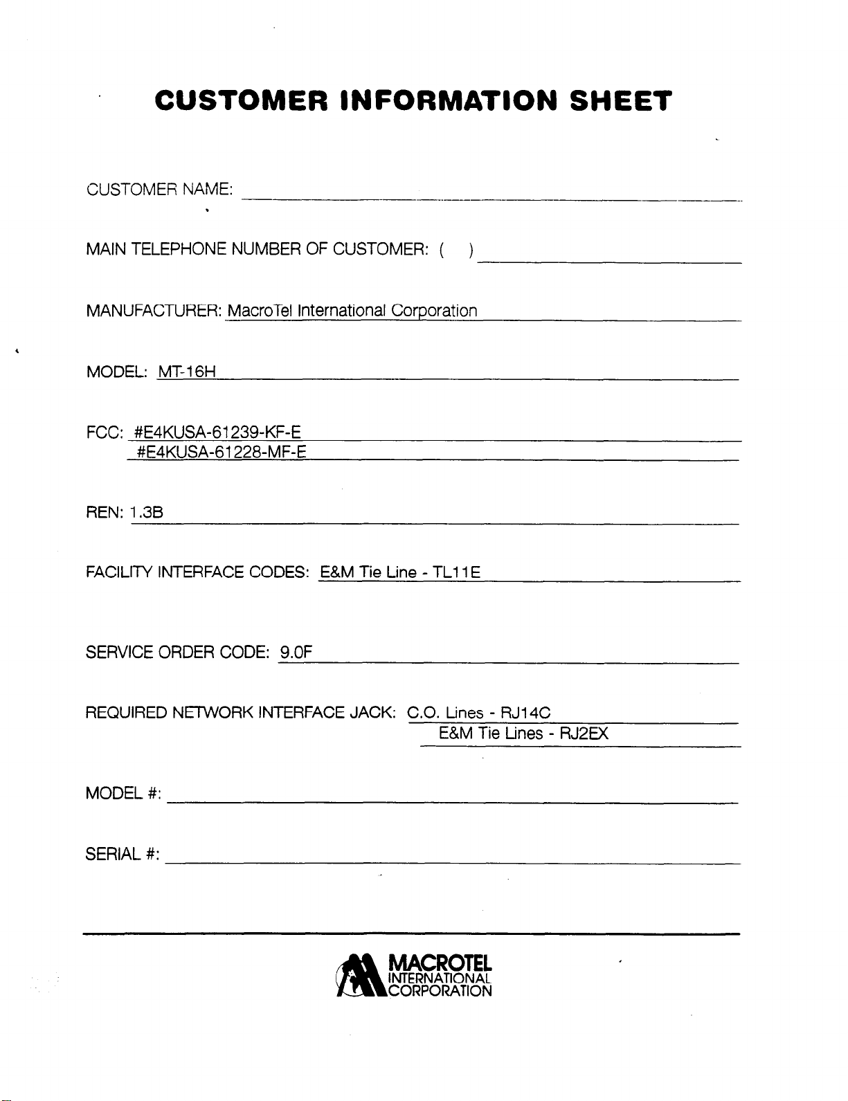
CUSTOMER INFORMATION SHEET
CUSTOMER NAME:
.
MAIN TELEPHONE NUMBER OF CUSTOMER: ( )
MANUFACTURER: MacroTel International Corporation
MODEL: MT-1 6H
FCC: #E4KUSA-61239-KF-E
#E4KUSA-61228-MF-E
REN:
FACILIN INTERFACE CODES: E&M Tie Line -
1.3B
-~__.------
TLl 1 E
---__.
SERVICE ORDER CODE: 9.OF
REQUIRED NlZ7VVORK INTERFACE JACK: C.O. Lines - RJ14C
E&M Tie tines - RJ2EX
MODEL #:
SERIAL #:
MACROTEL
INTERNATIONAL
?!b
CORPORATION
Table
uf
Contents
Safety Instructions
,
1
PURPOSE OF MANUAL ...........................................................................................................
1
GENERAL DESCRIPTION. . ...................................................................................................
INSTALLATION. .....................................................................................................................
PROGRAMMING. ....................................................................................................................
TROUBLESHOOTING.
2.
TELEPHONE COMPANY AND FCC REQUIREMENTS AND RESPONSIBILITIES.
RADIO FREQUENCY INTERFERENCE
3.
GENERAL DESCFUPTION
OVERVIEW .............................................................................................................................
GENERAL DESCRIPTION OF THE
CPU PROCESSOR UNIT ........................................................................................................
NETWORK CONTROL
POWER SUPPLY ....................................................................................................................
SYSTEM COMPONENTS
POWER SUPPLIES
DOORPHONE
EXPANSION CARDS ...........................................................................................................
LCD DISPLAY KIT
WALL MOUNT KIT
BATTERY BACKUP
SINGLE LINE TELEPHONES
ELECTRONIC TELEPHONE SETS
MT- 16T TELEPHONE SET ......... .._ .... I..
MAXIMUM SYSTEM CAPACITIES:
ELECTRICAL SPECIFICATIONS
MUSIC ON HOLD SPECIFICATIONS
EXTERNAL PAGING SPECIFICATIONS
KSU PHYSICAL CHARACTERISTICS
ENVIRONMENTAL SPECIFICATIONS
ELECTRONIC KEY PHONE AUDIBLE AND VISUAL INDICATIONS
SINGLE LlNE TELEPHONE AUDIBLE INDICATORS.
SYSTEM CONNECTION LAYOUT
.......................................................................................................................
...........................................................................................................
..............................................................................
......................................................................................................
KSU..
..........................................................................
..........................................................................................................
......................................................................................................
.................................................................................................................
..............................................................................................................
.............................................................................................................
............................................................................................................
.............................................................................................
.....................................................................................
......................................................................
MT- 16H
..........................................
................................................................................
..............................................................................
....................................................................................
................
..........................................................................
.............................................................................
.................................................. 12
..-...............-
...................................................
........................
..........................
1
1
1
1
... .
5
7
.:
7
8
9
9
9
10
10
10
10
10
1
1
11
..
_
11
12
13
13‘
13
13
14
16
17
4. MT-16H
FEATURE DESCRIPTIONS
...................................................................................
19
5. INSTALLATION
OVERVIEW
INSTALLATION PRECAUTIONS
EQUIPMENT VERIFICATION
SYSTEM COMPONENTS MT-16H
INSTALLATION LOCATION CHECKLIST
TOOLS CHECKLIST
MT- 16H FACILITIES LOCATION
MAIN DISTRIBUTION FRAME (MDF)
TERMINATING STATION CABLES AT THE
TERMINATING STATION CABLES AT KEYSET/SLT LOCATIONS
CENTRAL OFFICE LINE
KEY SERVICE UNIT
MOUNT THE
11 O/220 VOLTAGE CONNECTION
INSTALLING THE KEY SETS/SLT
TO CONNECT EACH STATION TO KSU
DIP SWITCH SETTING FOR STATIONS 7&8
STATION CABLING FOR SINGLE LINE PHONE
CONNECTION OF KEYSETS AND SINGLE LINE TELEPHONES
CONNECTING CENTRAL OFFICE LINES 1,2,3 AND 4
. . . . . . . . . . . . . . . . . . . . . . . . . . . . . . . . . . . . . . . . . . . . . . . . . . . . . . . . . . . . . . . . . . . . . . . . . . . . . . . . . . . . . . . . . . . . . . . . . . . . . . . . . . . . . . . . . . . . . .
. . . . . . . . . . . . . . . . . . . . . . . . . . . . . . . . . . . . . . . . . . . . . . . . . . . . . . . . . . . . . . . . . . . . . . . . . . . . . . . . . . . . . . . . . . . . . . . . . . . . . . . . . . . . . . . . . . . . . . . . ...-
. . . . . . . . . . . . . . . . . . . . . . . . . . . . . . . . . . . . . . . . . . . . . . . . . . . . . . . . . . . . . . . . . . . . . . . . . . . . . . . . . . . . . . . 27
. . . . . . . . . . . . . . . . . . . . . . . . . . . . . . . . . . . . . . . . . . . . . . . . . . . . . . . . . . . . . . . . . . . . . . . . . . . . . . . . . . . . . . . . . . . . 28
-...,-......._.......-....................._.........................._......__.. 28
-........_............................................................
. . . . . . . . . . . . . . . . . . . . . . . . . . . . . . . . . . . . . . . . . . . . . . . . . . . . . . . . . . .._............................................... 29
. . . . . . . . . . . . . . . . . . . . . . . . . . . . . . . . . . . . . . . . . . . . . . . . . . . . . . . . . . . . . . . . . . . . . . . . . . . . . . . . . . . . . .
. . . . . . . . . . . . . . . . . . . . . . . . . . . . . . . . . . . . . . . . . . . . . . . . . . . . . . . . . . . ..*................ 30
MDF
. . . . . . . . . . . . . . . . . . . . . . . . . . . . . . . . . . . . . . . . . . . . . . . . . . . . . . . . . . 31
*........................... 3 1
. . . . . . . . . . . . . . . . . . . . . . . . . . . . . . . . . . . . . . . . . . . . . . . . . . . . . . . . . . . . . . . . . . . . . . . . . . . . . . . . . . . . . . . . . . . . . . . . . . . . . 31
. . . . . . . . . . . . . . . . . . . . . . . . . . . . . . . . . . . . . . . . . . . . . . . . . . . . . . . . . . . . . . . . . . . . . . . . . . . . . . . . . . . . . . . . . . . . . . . . . . . . . . . . . . . . 31
KSU . . . . . . . . . . . . . . . . . . . . . . . . . . . . . . . . . . . . . . . . . . . . . . . . . . . . . . . . . . . . . . . . . . . . . . . . . . . . . . . . . . . . . . . . . . . . . . . . . . . . . . . . . . . . . . . . 32
. . . . . . . . . . . . . . . . . . . . . . . . . . . . . . . . . . . . . . . . . . . . . . . . . . . . . . . . . . . . . . . . . . . . . . . . . . . . . . . . . . . . 32
. . . . . . . . . . . . . ..*..................................................................... 33
. . . . . . . . . . . . . . . . . . . . . . . . . . . . . . . . . . . . ..*................................... 33
. . . . . . . . . . . . . . . . . . . . . . . . . . . . . . . . . . . . . . . . . . . . . . . . . . . . . . . . . . . . . . . . . . . 34
. . . . . . . . . . . . . . . . . . . . . . . . . . . . . . . . . . . . . . . . . . . . . . . . . . . . . . . . . . . . 34
. . . . . . . . . . . . . . . . . . . . . . . . . . . . . . . . . 35
. . . . . . . . . . . . . . . . . . ..*............................. 35
TO CONNECT CO/E&M TIE LINES 5,6, 7 and 8 (Expansion Card Required) . . . . . . . . . . . . . . . . . . 35
CONNECTION OF CENTRAL OFFICE LINES/
E&M TIE LlNES
SWITCH SETTINGS FOR MT-STUIC
TO INSTALL EXPANSION CARDS
. . . . . . . . . . . . . . . . . . . . . . . . . . . . . . . . . . . . . . . . . . . . . . . . . . . . . . . . . . . . . . . . . . . . . . . . . . . . . . . . . . . . . . . . . . . . . . . . . . . . . . . . . . . . . . . . . . . 36
. . . . . . . . . . . . . . . . . . . . . . . . . . . . . . . . . . . . . . . . . . . . . . . . . . . . . . . . . . . . . . . . . . . . . . . . . . . . . . . . . 37
. . . . . . . . . . . . . . . . . . . . . . . . . . . . . . . . . . . . . . . . . . . . . . . . . . . . . . . . . . . . . . . . . . . . . . . . . . . . . . . . . . . 37
INSTALLATION OF EXPANSION CARDS
CONNECTING EXTERNAL PAGING SPEAKERS
CONNECTING THE
DOORPHONE
AND
EXTERNAL PAGE AND DOORPHONE CONNECTIONS
INTERNAL MUSIC SOURCE
. . . . . . . . . . . . . . . . . . . . . . . . . . . . . . . . . . . . . . . . . . . . . . . . . . . . . . . . . . . . . . . . . . . . . . . . . . . . . . . . . . . . . . . . . . . . . . 39
CHANGE INTERNAL MUSIC SOURCE
EXTERNAL MUSIC SOURCE
CONNECTING A PRINTER
DIP SWITCH SETTINGS
SMDR FORMAT
. . . . . . . . . . . . . . . . . . . . . . . . . . . . . . . . . . . . . . . . . . . . . . . . . . . . . . . . . . . . . . . . . . . . . . . . . . . . . . . . . . . . . . . . . . . . . . . . . . . . . . . . . . . . . . . . 41
POWER FAILURE TRANSFER
BATTERYBACKUP
. . . . . . . . . . . . . . . . . . . . . . . . . . . . . . . . . . . . . . . . . . . . . . . . . . . . . . . . . . . . . . . . . . . . . . . . ..*................................. 43
LCD DISPLAY KIT INSTALLATION
MEMORY BATTERY INITIALIZE
6.
CUSTOMER DATABASE PROGRAMMING SHEETS
SOFTWARE PROGRAMMING CODES
PROGRAM #33 CLASS B DENY
PROGRAM #34 CLASS B ALLOW
PROGRAM #35 CLASS C DENY
PROGRAM #36 CLASS C ALLOW
PROGRAM #37 CLASS 0 ALLOW
. . . . . . . . . . . . . . . . . . . . . . . . . . . . . . . . . . . . . . . . . . . . . . . . . . . . . . . . . . . . . . . . . . . . . . . . . . . . . . . . . . . . . . . . . . . . . 39
OR
TERMINAL
. . . . . . . . . . . . . . . . . . . . . . . . . . . . . . . . . . . . . . . . . . . . . . . . . . . . . . . . . . . . . . . . . . . . . . . . . . . . . . . . . . . . . . . . . . . . . . . . . . . . . 41
. . . . . . . . . . . . . . . . . . . . . . . . . . . . . . . . . ..*....................................................... 42
_...............................*_...........*._............ _ . . . . .._........ 43
_.....-.._...........--...............-...-..-.....................~.........
. . . . . . . . . . . . . . . . . . . . . . . . . . . . . . . . . . . . . . . . . . . . . . . . . . . . . . . . . . . . . . . ..~..........
. . . . . . . . . . . . . . . . . . . . . . . . . . . . . . . . . . . . . . . . . . . . . . . . . . . . . . . . . . . . . . . . . . . . . . . . . . . . . . . . . . . . . . . . 51
. . . . . . . . . . . . . . . . . . . . . . . . . . . . . . . . . . . . . . . . . . . . . . ..~....................................
. . . . . . . . . . . . . . . . . . . . . . . . . . . . . . . . . . . . . . . . . . . . . . . . . . . . . . . . . . . . . . . . . . . . . . . . . . . . . . . . . . . . . . . . 52
. . . . . . . . . . . . . . . . . . . . . . . . . . . . . . . . . . . . . . . . . . . . . . . . . . . . . . . . . . . . . . . . . . . . . . . . . . . . . . . . . . . . . 52
. . . . . . . . . . . . . . . . . . . . . . . . . . . . . . . . . . . . . . . . . . . _ . . . . . . . . . . . . . . . . . . . . . . ~ . . . . . . . . . . . . . . . . . 53
PROGRAM #61 NIGHT MODE RlNGING
PROGRAM #62 DAY MODE RINGING
. . . . . . . . . . . . . . . . . . . . . . . . . . . . . . . . . . . . . . . . . . . . . . . . . . . . . . . . . . . . . . . . . . . . . . . . . . . . . 54
. . . . . . . . . . . . . . . . . . . . . . . . . . . . . . . . . . . . . . . . . . . . . . . . . . . . . . . . . . . . . . . . . 36
. . . . . . . . . . . . . . . . . . . . . . . . . . . . . . . . . . . . . . . . . . . . . . . . . . . . . . . . . . . . . . . . . . . . . . . 37
. . . . . . . . . . . . . . . . . . . . . . . . . . . . . . . . . . . . . . . . . . . . . . . . . . . . . . . . . . . 38
DOORLOCK CONTROL . . . . . . . . . . . . . . . . . . . . . . . . . . . . . . . . 38
. . . . . . . . . . . . . . . . . .._............................ 38
. . . . . . . . . . . . . . . . . . . . . . . . . . . . . . . . . . . . . . . . . . . . . . . . . . . . . . . . . . . . . . . . . . . . . . . . . . . . 39
(SMDR) . . . . . . . . . . . . . . . . . . . . . . . . . . . . . . . . . . . . . . . . . . . . . . . . . . . . . . 4 1
. . . . . . . . . . . . . . . . . . . . . . . . . . . . . . . . . . . . . . . . . . . .
. . . . . . . . . . . . . . . . . . . . . . . . . . . . . . . . . . . ..*................................... 53
. . . . . . . . . .
27
37
28
30
44
45
50
51

SYSTEM
SPEED DIALING SHEET . . . . . . . . . . . . . . . . . . . . . . . . . . . . . . . . . . . . . . . . . . . . . . . . . . . . . . . . . . . . . . . . . . . . . . . . . . . . . . . . . . . . 5.5
.
7.
PROGRAMMING INSTRUCTIONS
OVERVIEW . . . . . . . . . . . . . . . . . . . . . . . . . . . . . . . . . . . . . . . . . . . . . . . . . . . . . . . . . . . . . . . . . . . . . . . . . . . . . . . . . . . . . . . . . . . . . . . . . . . . . . . . . . . . . . . . . . . . . . . . ... 57
ENllmNG/~~FR~
ENABLING
CHANGE
STATION
MODIFICATION OF PASSWORD (PROGRAM 21) , . . . . . . . . . . . . . . . . . . . . . . . . . . . . . . . . . . . . . . . . . . ..*............. 62
DTMF
DIAL PULSE MAKEBREAK RATIO/TOLL CHECK TIMER (PROGRAM 23) . . . . . . . . . . . . . . . . . . . 64
SOFTWARE VERSION OF SYSTEM AND TELEPHONE (PROGRAM 24) . . . . . . . . . . . . . . . . . . . . 6 1
SYSTEM
OPTIONAL
EXTERNAL
TRUNK
STATION
LINE ACCESS BY STATION
CO
INTERNAL
CLASS
DENY
ALLOW CODES
DENY
ALLOW CODES FOR CLASS OF SERVICE 2 (C) (PROGRAM 36) . . . . . . . . ..I...................... 77
ALLOW CODES
TOLL RESTRICTION OVERRIDE (PROGRAM 0 1,02,03) . . ..e........................................... 79
TELEPHONE
TRUNK NAMES (PROGRAM 39) ****
ASSIGN
CO LINE DlAL MODE SELECTION (TONE/PULSE) (PROGRAM 42)
CO LINE ENABLED FOR SERVICE (PROGRAM 43) . . . . . . . . . . . . . . . . . . . . . . . . . . . . . . . . . . . . . . . . . . . . . . . . . . . . . . 84
LINE DEFINITION (PROGRAM
CO
EXTERNAL
PRIVACY
DIAL 9 ACCESS (PROGRAM 47)
COMMON
CO FLASH TIMING (PROGRAM 50)
PABX
HOLD
TRANSFER
ALARM TIME DURATION (PROGRAM 54) . . . . . . . . . . . . . . . . . . . . . . . . . . . . .._........._......................... 94
TIME
EXECUTIVE PRIORITY INTRUSION TONE INTERVAL TIMER (PROGRAM 56)......96
TO CO CALL DURATION.TIMER (PROGRAM 57) . . . . . . . . . . . . . . . . . . . . . . . . . . . . . . . . . . . . . . . . . . . . . . . . . . . 97
CO
AUTO TIMER (PROGRAM 58)
DOOR
LINE RINGING MODE (PROGRAM
C.0
NIGHT
DAY
DOORPHONE
RING OVER PAGE (PROGRAM 64)
USER PROGRAMMING
USER PASSWORD
ON & OFF (PROGRAM
MUTING TO STATION
INITIALIZATION (PROGRAM
CLASS OF SERVICE
FORWARD (PROGRAM
LINE FORWARD (PROGRAM
TOLL CLASS OF SERVICE
PAGING - ALLOW
OF SERVICE - TOLL RESTRICTION . . . . . . . . . . . . . . . . . . . . . . . . . . . . . . . . . . . . . . . . . . . . . . . . . . . . . . . . . . . . . . . . . . . . 73
CODES FOR CLASS OF
FOR CLASS
CODES FOR CLASS OF
FOR CLASS
TYPE (PROGRAM
PRIVACY (PROGRAM
CALL FORWARDING
RELEASE/FLASH (PROGRAM
AUDIBLE RING (PROGRAM
FLASH TIMING (PROGRAM
RECALL TIMER (PROGRAM
RECALL TIME (PROGRAM
& DATE DISPLAY (PROGRAM
RELEASE TIMER (PROGRAM
MODE RINGING (PROGRAM
MODE RINGING (PROGRAM
RING ASSIGNMENT
. . . . . . . . . . . . . . . . . . . . . . . . . . . . . . . . . . . . . . . . . . . . . . . . . . . . . . . . . . . . . . . . . . . . . . . . . . . . . . . . . . . . . 57
MODE(FROGRAM~) . . . . . . . . . . . . . . . . . . . . . . . . . . . . . . . . . . . . . 58
MODE
(PROGRAM 05)
19) l *** . . . . . . . . . . . . . . . . . . . . . . . . . . . . . . . . . . . . . . . . . . . . . . . . . . . . . . . . . . . . . . . . . . . . . . . 61
USER (PROGRAM
(PROGRAM
27) . . . . . . . . . . . . . . . . . . . . . . . . . . . . . . . . . . . . . . . . . . . . . . . . . . . . . . . . . . . . . . . . . . . . . . . . . . 69
USER (PROGRAM
OR DENY (PROGRAM
SERVICE l(B) (PROGRAM 33) . . . . . . . . . . . . . . . . . . . . . . . . . . . . . . . . . . . . . 74
OF SERVICE
SERVICE 2
OF SERVICE
38) . . . . . . . . . . . . . . . . . . . . . . . . . . . . . . . . . . . . . . . . . . . . . . . . . . . . . . . . . . . . . . . . . . . . . . . . . . . . . . . . . . 80
41) l ** . . . . . . . . . . . . . . . . . . . . . . . . . . . . . . . . . . . . . . . . . . . . . . . . . . . . . . . . . . . . . . . . . . . . . . . . . . . . 82
44) . . . . . . . . . . . . . . . . . . . . . . . . . . . . . . . . . . . . . . . . . . . . . . . . . . . . . . . . . . . . . . . . . . . . . . . . . . . . . 85
(PROGRAM
. . . . . . . . . . . . . . . . . . . . . . . . . . . . . . . . . . . . . . . . . . . . . . . . . . . . . . . . . . . . . . . . . . . . . . . . . . . . . . . . . 90
5 1) . . . . . . . . . . . . . . . . . . . . . . . . . . . . . . . . . . . . . . . . . . . . . . . . . . . . . . . . . . . . . . . . . . . . . . . . . . . . 9 1
52) l * . . . . . . . . . . . . . . . . . . . . . . . . . . . . . . . . . . . . . . . . . . . . . . . . . . . . . . . . . . . . . . . . . . . . . . 92
. . . . . . . . . . . . . . . . . . . . . . . . . . . . . . . . . . . . . . . . . . . . . . . . . . . . . . . . . . . . . . . . . . . . . . . . . . . . . . . . . . . . . . . . . . . 98
62) . . . . . . . . . . . . . . . . . . . . . . . . . . . . . . . . . . . . . . . . . . . . . . . . . . . . . . . . . . . . . . . . . . . . . . . . . . . 102
(PROGRAM
. . . . . . . . . . . . . . . . . . . . . . . . . . . . . . . . . . . . . . . . . . . . . . . . . . . . . . . . . . . . . . . . . . . . . . . . . . . . . . . . .
(PROGRAM
*** . . . . . . . . . . . . . . . . ..I....... . . . . . . . . . . . . . . . . . . . . . . . . . . . . . . . . 60
22) . . . . . . . . . . . . . . . . . . . . . . . . . . . . . . . . . . . . . . . . . . . . . . . . . . . . 63
25)
. . . . . . . . . . . . . . . . . . . . . . . . . . . . . . . . . . . . . . . . . . . . . . . . . . . . . . . . . . . . . . . . . . . . 62
26) . . . . . . . . . . . . . . . . . . . . . . . . . . . . . . . . . . . . . . . . . . . . . . . . . . . . . . . . . . . 63
29) * ** *
(PROGRAM
. . . . . . . . . . . . . . . . . . . . . . . . . . . . . . . . . . . . . . . . . . . . . . . . . . . . . . . . . . . . . . . . . . . . . . . . . . . . . . 81
DIAL ACCESS (PROGRAM 48) ** . . . . . . . . . .._......... 88
49)
53)
55) . . . . . . . . . . . . . . . . . . . . . . . . . . . . . . . . . . . . . . . . . . . . . . . . . . . . . . . . . . . . . . . . . . . . . . . . 95
59)** . . . . . . . . . . . . . . . . . . . . . . . . . . . . . . . . . . . . . . . . . . . . . . . . . . . . . . . . . . . . . . . . . . . . . 99
60) . . . . . . . . . . . . . . . . . . . . . . . . . . . . . . . . . . . . . . . . . . . . . . . . . . . . . . . . . . . . . . . . . . . . . 96
6 1) * l . . . . . . . . . . . . . . . . . . . . . . . . . . . . . . . . . . . . . . . . . . . . . . . . . . . . . . . . . . . . . . . . . . 10 1
. . . . . . . . . . . . . . . . . . . . . . . . . . . . . . . . . . .._._.._.................. 69
l(B) (PROGRAM
(C) (PROGRAM
3 (D) (PROGRAM
45) . . . . . . . . . . . . . . . . . . . . . . . . . . . . . . . . . . . . . . . . . . . . . . . . . . . . . . . . 86
46)
. . . . . . . . . . . . . . . . . . . . . . . . . . . . . . . . . . . . . . . . . . . . . . . . . . . . . . . . . . . . . . . . . . 87
** . . . . . . . . . . . . . . . . . . . . . . . . . . . . . . . . . . . . . . . . . . . . . . . . . . . . . . . . . . . . . . . 89
. . . . . . . . . . . . . . . . . . . . . . . . . . . . . . . . . . . . . . . . . . . . . . . . . . . . . . . . . . . . . . . . . . . . 93
63) . . . . . . . . . . . . . . . . . . . . . . . . . . . . . . . . . . ..“.............. 103
04)*** . . . . . . . . . . . . . . . . . . . . . . . . . . . . . . . . . . 59
30) . . . . . . . . . . . . . . . . . . . . . . . . . . . . . . . . . . . . . . . . . . . . . . . . . . . 70
3 1) . . . . . . . . . . . . . . . . . . . . . . . . . . . . . . . . . . . . . . . . . . . . . . . . . 7 1
32) . . . . . . . . . . . . . . . . . . . . . . . . . . . . . . . . . . . . . . . . . . . . 72
34) . . . . . . . . . . . . . . . . . . . . . . . . . . . . . . . . . . 75
35) . . . . . . . . . . . . . . . . . . . . . . . . . . . . . . . . . . . . 76
37) . . . . . . . . . . . . . . . . . . . . . . . . . . . . . . . . 78
. . . . . . . . . . . . . . . . . . . . . . . . . . . . . . . . . .83
104

DISA SECURITY
DO NOT DISTURB STATUS (PROGRAM 66) * **
HUNT GROUP RING MODE (PROGRAM 67)
INTERNAL
STATION HUNT GROUPS (PROGRAM 69) * **
CODE
(PROGRAM
65) ***
PAGE ZONE ASSIGNMENTS
.................................................................
..........................................................
.................................................................
(PROGRAM
68)
...................................................
ATTENDANTKEYSET DESIGNATION (PROGRAM 70)
SYSTEM
SYSTEM
EXECUTIVE
BOSS/SECRETARY COMBINATION (PROGRAM 73)
CAMP ON TONE TIMER (PROGRAM 74)**
AUTO REDIAL ATTEMPTS (PROGRAM 75)
TRANSFER
SINGLE LINE HOOKFLASH TIME (PROGRAM 77) **
SPEED DIAL
PROGRAMMING
SPEED DIAL TOLL
PRIORITY
RECALL
(PROGRAM
DESTINATION
.......................................................................
RESTRICTION
72).
.......................................................................
(PROGRAM
(PROGRAM
..................................................
...................................................................
l l
.............................................................
**. ............................................
76)
.................................................
DISA LINE ASSIGNMENT PROGRAM (PROGRAM 78) ***
CENTIWWBX CODE (FROGRAM 79) * * * *
..................................................................
STATION BASIS KEY ASSIGNMENT (PROGRAM 18) l **
SOFT KEY PROGRAMMING (PROGRAM 80)
KEY TEST (PROGRAM 81)
...............................................................................................
STATUS MESSAGE DISPLAY (PROGRAM 82)
OFF HOOK ROUTING (PROGRAM 83) * * * *
HOTLINE DELAY TIME (PROGRAM 84) * * **
DELAYED RINGING (PROGRAM 85) ****
DTMF DURATION (PROGRAM 86)****
HALT PROCESSING (PROGRAM 90) * * *
................................................................
.............................................................
..................................................................
..............................................................
....................................................................
.........................................................................
l
.....................................................................
***
..................................
................. .
7 1)
..........................
...................................
........................................
..........................................
..-
......
105
106‘
107
.108
109
110 .
1 1 1
.I
12
1 13
114
115
116
1 17
1 18
119
120
121
122
124
125
127
128
128
129
130
8. TROUBLESHOOTING DURING INSTALLATION
DIP SWITCHES
. . . . . . . . . . . . . . . . . . . . . . . . . . . . . . . . . . . . . . . . . . . . . . . . . . . . . . . . . . . . . . . . . . . . . . . . . . . . . . . . . . . . . . . . . . . . . . . . . . . . . . . . . . . . . . . . . . .
. . . . . . . . . . . . . . . . . . . . . . . . . . . . . . . . . .
. . . . . . . . . . . . . . . . . . . . . . .
131
132
IMPORTANT SAFETY INSTRUCTIONS
Read and understand all instructions.
1.
Follow all warnings and instructions marked on the product.
Jnplug this product from the wall outlet before cleaning. Do not use liquid cleaners or aerosol cleaner. Use a damp cloth for cleaning.
Do not use this product near water, for example, near a bathtub, wash bowl, kitchen sink, laundry tub or in a wet basement.
4.
Do not place this product on an unstable cart, stand or table. The product may fall and be seriously damaged.
5.
Slots and openings In the cabinet and the back or bottom are provided for ventilation and to protect it from overheating. These openings must
6.
not be blocked or covered. Do not block openings by placing the product on a bed, sofa, rug or similar surface. This product should never
be placed near or over a radiator or heat register, nor in a built-in installation, unless properly ventilated.
This product should be operated only from the type of power source indicated on the marking level.
7.
supply to your home, consult your dealer or local power company.
If provided with a grounded-type attachment plug, this product is equipped with a three-wire grounding type plug, a plug having a third ground-
0.
ing pin. This plug will only fii into a grounding type power outlet. Do not defeat the safety purposes of the grounding type plug. If provided
with a polarized attachment plug, this product is equipped with a polarized line plug (a plug having one blade wider than the other). As a safety feature, this plug will fit into the power outlet only one way. If you are unable to insert the plug fully into the outlet, try reversing the plug. If
the plug still does not fit, contact your electrician to replace your obsolete outlet. Do not defeat the safety purposes of the polarized plug.
Do not allow anything to rest on the power cord. Do not locate this product where the cord will be abused by people walking on it.
9.
Do not overload wall outlets and extension cords as this can result in the risk of fire or electric shock.
, 10.
Never push objects of any kind into the product through cabinet slots as they may touch dangerous voltage points or short out parts that could
11.
result in a risk of fire or electric shock. Never spill liquid of any kind on the product.
To reduce the risk of electric shock, do not disassemble this product. When service or repair work is required, take it to a qualified service-
12.
man. Opening or removing covers may expose you to dangerous voltages or other risks. Incorrect reassembly can cause electric shook when
the appliance is subsequently used.
Unplug this product from the wall outlet and refer servicing to qualified service personnel under the following conditions:
13.
A. When the power supply cord or plug is damaged or frayed.
B. If liquid has been spilled into the product.
C. If the product has been exposed to rain or water.
D. If the product does not operate normally by following the operating instructions. Adjust only those controls that are covered by the
operating instructions. Improper adjustment of other controls may resutt in damage and will often require extensive work by a qualified
technician to restore the product to normal operation.
5 If the product has been dropped or the cabinet has been damaged.
.
If the product exhibits a distinct change in performance.
If you are not sure of the type of power
14.
Avoid using a telephone (other than a cordless type) during an electrical storm. There may be a remote risk of electric shook from lightning.
Do not use the telephone to report a gas leak in the vicinity of the leak.
15.
Never install telephone wiring during a lightning storm.
16.
Never install telephone jacks in wet locations unless the jack is specifically designed for wet locations.
17.
Never touch uninsulated telephone wires or terminals unless the telephone line has been disconnected at the network interface.
18.
Use caution when installing or modifying telephone lines. The exclamation point within an equilateral triangle is intended to alert the user to
19.
the presence of important operating and maintenance (servicing) instructions rn the literature accompanying the product. The installation
instructions provided with equipment intended to be locally powered over telecommunications wiring systems shall include all of the following:
A. The current limitations and maximum overcurrent protection for Level C crrcurts.
B. Reference to the specific power supply or current limiting device provided with the product and,
C. Detailed instructions showing the proper method of installation and connectrons to the telecommunications wiring system.
To
reduce the risk of fire or injury, read and follow these instructions:
Use only the battery backup kit as provided by MacroTel.
1.
In case of fire, do not dispose of the battery(ies). The cell may explode. Check wrth local codes for possible special disposal instructions.
2.
Do not open or mutilate battery(ies) Released electrolyte is corrosive and may cause damage to the eyes or Skin. It may be. toxic if swallowed.
3.
Exercise care in handling batteries in order not to short the battery with conductrng materials such as rings, bracelets and keys. The battery
4.
or conductor may overheat and cause bums.
Charge the battery(ies) provided with or identified for use with this product only In accordance with instructions and limitations specified in this
5.
manual.
Observe proper polarity orientation between the battery(ies) and battery chargers.
6.
Do not mix old and new batteries in this product (applies to products employing more than one user-replaceable secondary battery).
7.
Do not mix batteries of different sizes or from different manufacturers in this product (applies to products employing more than one user-replace-
8.
-ble secondary battery).
Se&ion
l-
ICON KEY
Warning
8
Danger
>
Important
Notes
PURPOSEOFMANUAL
This manual details the instructions and procedures required to install, program and
maintain the MT-16H Electronic Key Telephone System. For convenience, the
manual has been written in separate sections. They are as follows:
GENERAL DESCRIPTION:
Provides an overview of the system operation, capacities and physical characteristics.
INSTALLATION:
Detailed installation instructions to enable the installer to complete the installation
of the KSU and associated equipment.
PROGRAMMING:
Step by step procedures are provided that allow the installer to program the
customer database. Programming sheets can be left onsite.
TROUBLESHOOTING!
The last section covers troubleshooting procedures to be followed should the
installer encounter any difficulties.
- TELEPHONE COMPANY AND FCC
REQUlREMENTS AND RESPQNSIBILITIES
In compliance with the requirements of Part 68 of the FCC Rules and Regulations
for the connection of a terminal system (this device is classified as a terminal system)
to the telephone network and for your convenience, the following information is
presented:
1. Notification to the Telephone Company
Customers connecting terminal equipment to the telephone network shall, upon
request of the telephone company, inform the telephone company of the particular
line(s) to which such connection is made, the FCC registration number (see the labe
on the side of unit) and ringer equivalence number (REN)of the registered terminal
equipment.
The REN is useful to determine the quantity of devices you may connect to your
telephone line and still have all of those devices ring when your telephone number is
called. In most, but not all areas, the sum of the RENs of all devices connected to
one line should not exceed five (5.0). T
may connect to your line, as determined by the REN, you should contact your local
telephone company to determine the maximum REN for your calling area.
o b e certain of the number of devices you
2. Direct connection to a party line or coin-operated telephone line is
prohibited.
3. Incidence of Harm to the Telephone Lines
Should terminal equipment cause harm to the telephone network, the telephone
company shall, where practical, notify the customer that service may be temporarily
discontinued. However, where prior notice is not practical, the telephone company
may temporarily discontinue service forthwith, if such action is reasonable in the
circumstances. In case of such unnotified temporary discontinuance of service, the
telephone company shall:
a) -Promptly notify the customer of such temporary discontinuance of service.
b) Afford the customer the opportunity to correct the situation which gave rise to
the temporary discontinuance.
c)
Inform the.customer of the right to bring a complaint to the Commission
pursuant to the procedures set out in Subpart E of Part 68 of FCC Telephone
Equipment Rules.
_
4.
Compatibility of the Telephone Network and Terminal Equipment
Availability of Telephone Interface Information
4
Technical information concerning interface parameters and specifications
not specified in FCC Rules, including the number of Ringers which may be
connected to a particular line, which is needed to permit Terminal
Equipment to operatein-a manner compatible -with the Telephone
Company communications facilities, shall be provided by the Telephone
Company upon customer’s request.
Changes in Telephone Company Communications Facilities,
b)
Equipment, Operations and Procedures
The Telephone Company may makechanges in its communications
facilities, equipment, operations or procedures, where such action is
reasonable required in the operation of its business and is not inconsistent
with the rules and regulations in FCC Part 68 of the FCC Rules and
Regulations. If such changes can be reasonable expected to render any
customer’s Terminal Equipment incompatible with Telephone Company
Communications Facilities, or require modification or alteration of such
Terminal Equipment, or otherwise materially affect its use or performance,
the customer shall be given adequate notice in writing to allow the customer
an opportunity to maintain uninterrupted service.
_
5. Dual Registration Notification
When the MT-16H
selection of outgoing lines, it is considered to be a hybrid system. Therefore, it
must be registered as such. Because of this duality, the FCC has granted the MT-
l6H
system a dual registration. The installer is required to notify the telephone
operating company of the correct registration number that reflects the
configuration of the installation. The installer may be required to certify in
writing to the telephone company how the system is configured.
is installed and programmed to have manual and automatic
RADIO FREQUENCY INTERFERENCE
This equipment generates and uses radio frequency energy and if not installed and
used properly, that is in strict accordance with the manufacturer’s instructions, may
cause interference to radio and television reception. It has been type-tested and
.found to comply withthe limits foraClass A. computing device in accordance with
the specifications in Subpart J of Part 15 of FCC Rules, which are designed to
provide reasonable protection against such interference in a residential installation.
However, there is no guarantee that interference will not occur in a particular
installation. If this equipment does cause interference to radio or television
reception, which can be determined by turning the equipment off and on, the user is
encouraged to try to correct the interference by one or more of the following
measures:
l
Reorient the receiving antenna
l
Relocate the equipment with respect to the receiver
l
Move the equipment away from the receiver
0 Plug the equipment into a different outlet so that equipment and receiver are on
different branch circuits.
5
.-._ ._
section
3 ..
GENERAL
DE§CFWTION
I
OVERVIEW
The general description section provides detailed information of the operation of the
MT-16H Electronic Key Telephone System. The CPU, network interface and
system components are described in order to provide a working knowledge of the
equipment and its operation.
’
GENERAL DESCRIPTION OF THE KSU
The system architecture of the MT-16H is designed with “state of the art”
components and high quality design criteria. The system is organized into three
major sections: The Central Processing Unit, the Speech Path Network and
Interface, and the Power Supply section.
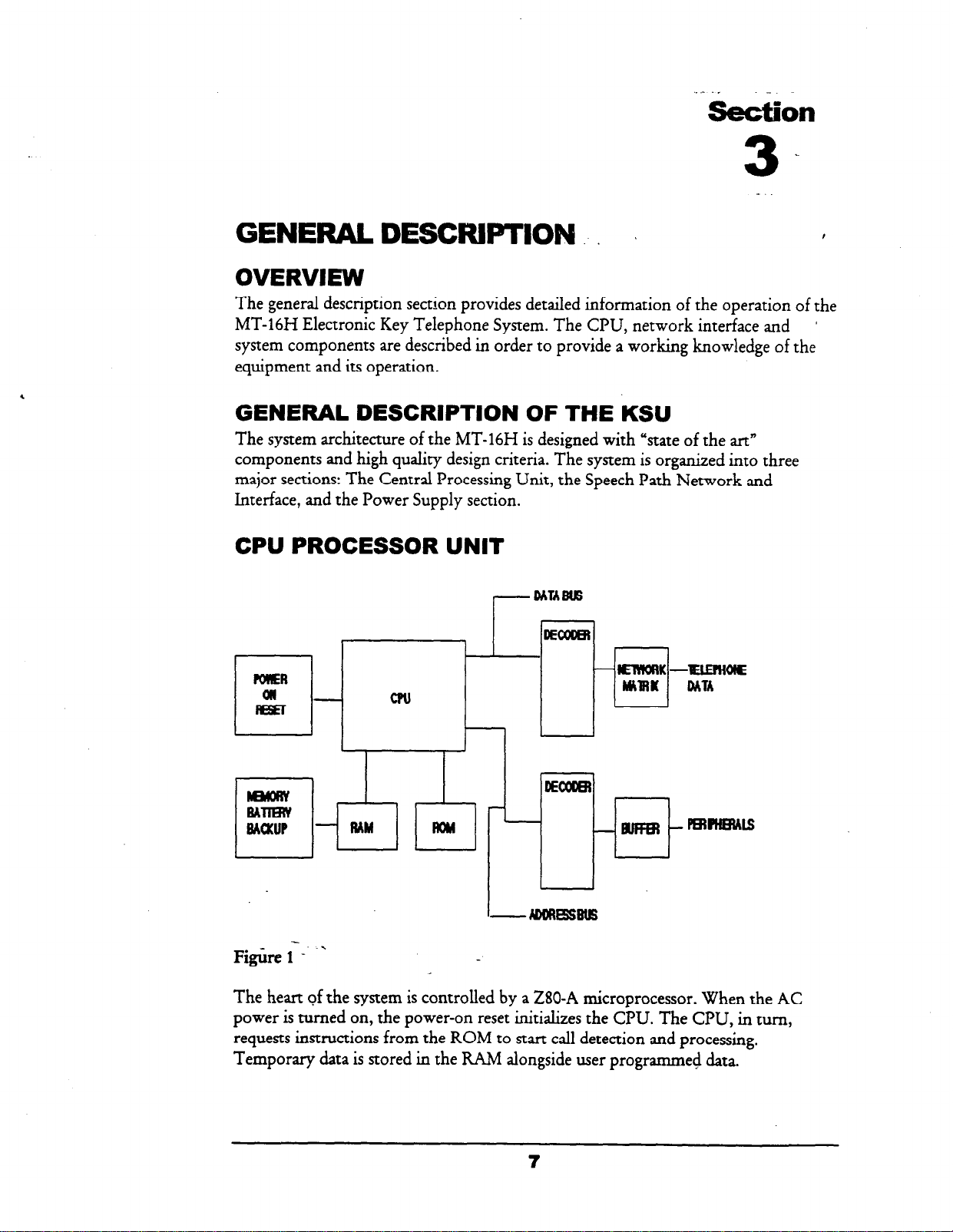
CPU
,
The heart of the system is controlled by a 280-A microprocessor. When the AC
power is turned on, the power-on reset initializes the CPU. The CPU, in turn,
requests instructions from the ROM to start call detection and processing.
Temporary data is stored in the RAM alongside user programmed data.
The user programmed data is backed up by a 3.7 volt NICAD battery that isunder
constant trickle charged by the KSU power supply. The NICAD is also used to
provide backup voltage for the real time clock. The NICAD battery will protect the
speed dial numbers and customer database until the power.outage exceeds
approximately 40 hours.
Memory
power
backup circuitry is monitored by voltage detecting circuitry
controlled by the CPU and, in turn, works with the power supply circuitry,
When the AC power is turned ON, the NICAD recharges.
which
monitors the DC output of the power supply.
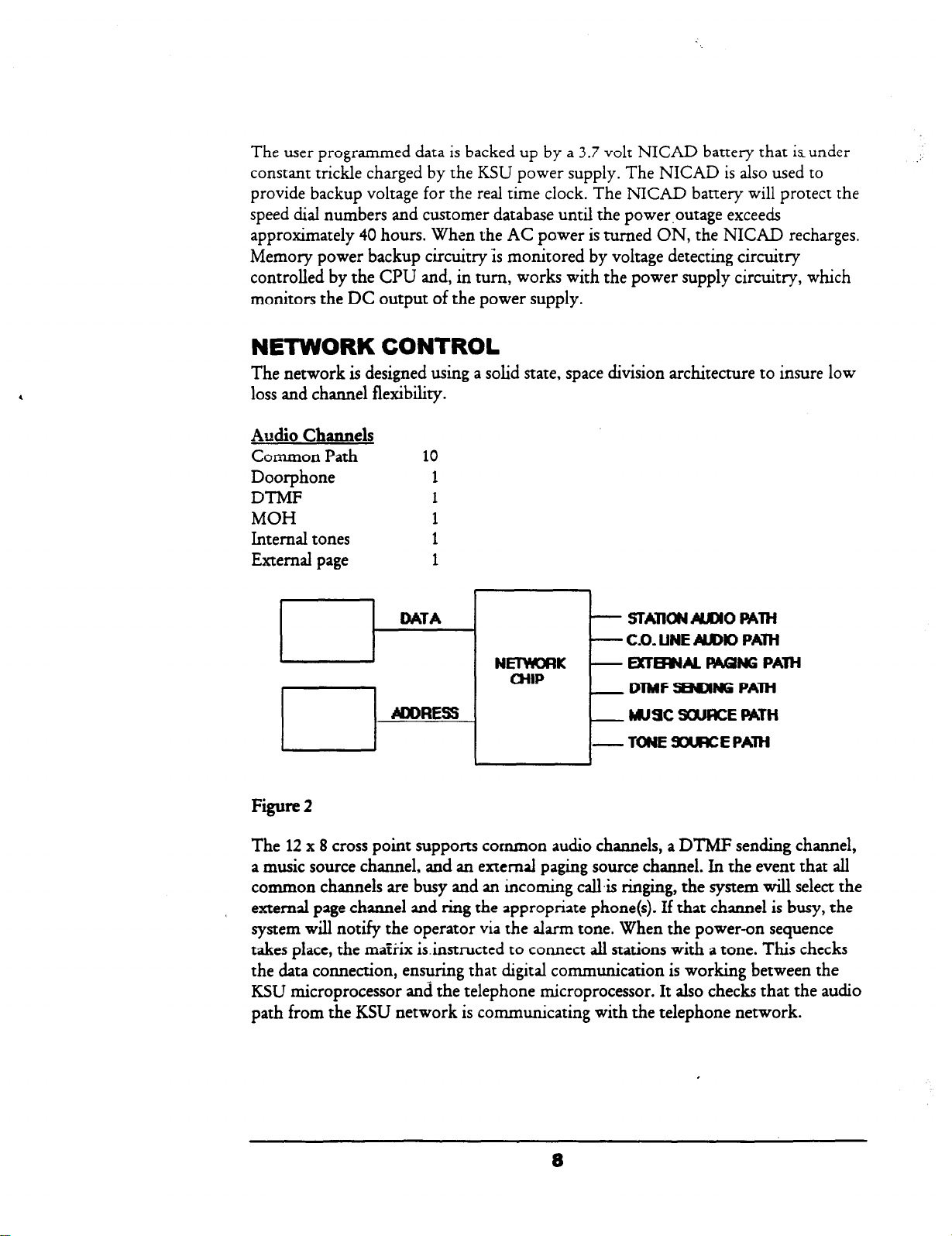
NETWORK CONTROL
The network is designed using a solid state, space division architecture to insure low
loss and channel flexibility.
Audio Channels
CoLmmon Path
Doorphone
DTMF
MOH
Internal tones
External page
10
1
1
1
1
1
DATA - STAmONMO PATH
- CO. UNE AIIDK) PAW
NElYEORK - EXTB’UL FWWG PATH
/
Fire 2
The
12 x 8
CHIP
CYIDRESS
cross point supports common audio channels, a DTMF sending channel,
_ DlMF WNG PAM
_ W9C SOURCE
-TONESOWCEPAlH
PATH
a music source channel, and an external paging source channel. In the event that all
common channels are busy and an incoming callis ringing, the system will select the
external page channel and ring the appropriate phone(s). If that channel is busy, the
system will notify the operator via the alarm tone. When the power-on sequence
takes place, the matrix isinstructed to connect all stations with a tone. This checks
the data connection, ensuring that digital communication is working between the
KSU microprocessor and the telephone microprocessor. It also checks that the audio
path from the KSU network is communicating with the telephone network.
8
POWER SUPPLY
The power supply section consists of components which change 1 lo/220 AC
voltage into the DC voltage which the integrated circuits use. Working in
conjunctionwith this circuitry, the
MT-16H
employs an on-line monitoring circuit
which detects under-voltage and over-voltage.
In the event the system loses AC voltage and the system battery backup has been
installed, the system detects when the batteries have discharged to such a rate that
the KSU is no longer usable. Instead of allowing the batteries to completely
discharge and become damaged, the system disconnects the batteries.
When AC voltage is restored to the KSU, the circuitry also monitors the charging of
the batteries. Charging will take place until the monitor circuit detects that the
batteries are in a charged state; which, in turn, turns off the charging circuit thereby
preventing the batteries from being overcharged.
SYSTEM COMPONENTS
The basic MT-16H cabinet is a 408 configuration expandable to a 612 and 816
configuration. The 408 cabinet provides for 4 central office lines, 1 door-phone and 8
electronic telephones. Two (2) of the 8 telephones are optionally selectable as
keyphones or single line telephones. Included in the cabinet is a ring generator for
single line telephones, a power supply PCB and the.main PCB. The following are
also contained in the main PCB:
l
280-A Microprocessor
l
Associated logic and memory circuitry
l
Real-time clock
l
RAM Battery backup
l
System timer
l
Speech path network circuit
l
External paging circuitry
l
Music on hold circuitry
POWER SUPPLIES
l
AC to DC rectification
l
_ External. system battery backup monitoring and control
l
*
DC battery
l
Battery backup
l
Ring generator for single line telephones
input
fuse’
9
_-
DOORPHONE
The MT-16H main PCB contains circuitry for one door-phone. Calling to and from
the KSU is standard. A door lock relay contact is also provided. The user, after
answering the call, may press-the door key (or dial 3) which, in turn, activates the
relay. Database Programming.activates the hardware.
EXPANSION CARDS
The MT-16H KSU supports the following three expansion cards:
MT-STU/A
Provides an additional capacity of 2 CO lines and 4 keysets. Programming activates
the additional CO lines and keysets.
MT-STU/B
Provides an additional capacity of 2 CO lines and 4 single line telephone circuits.
ramming activates the additional CO lines and single line telephones.
Prog
MT-STU/C
Provides an additional capacity of 2 CO lines or 2 E&M tie lines and 4 keysets.
amming activates the additional CO or E&M Lines and keysets.
Progr
SMDR CARD
This card is used to record details for calls made to the public switch network. A
printer or monitor is required.
LCD DISPLAY KIT
The LCD Display Kit is field installed and allows the user to upgrade to a display
telephone without having to replace the original telephone. No programming is
needed to enable this feature.
WALL MOUNT KIT
The WMK is a dual function kit which allows the phone to be attached to a wall in
a vertical manner or by reversing the unit, provides a 28 degree elevation to the
telephone.
BATTERY BACKUP.,
MacroTel provides an optional backup kit (PN # 2208037) for the MT-16H. This is
to be used when commercial power has failed. When fully charged, the batteries will
provide power for 6 to 8 hours, depending on usage.
SINGLE LINE TELEPHONES
Any
industrial standard single line telephone may be installed on the
MT-16H.
The
total ringer equivalency should not exceed 5.OB per single line port or damage to the
system might result.
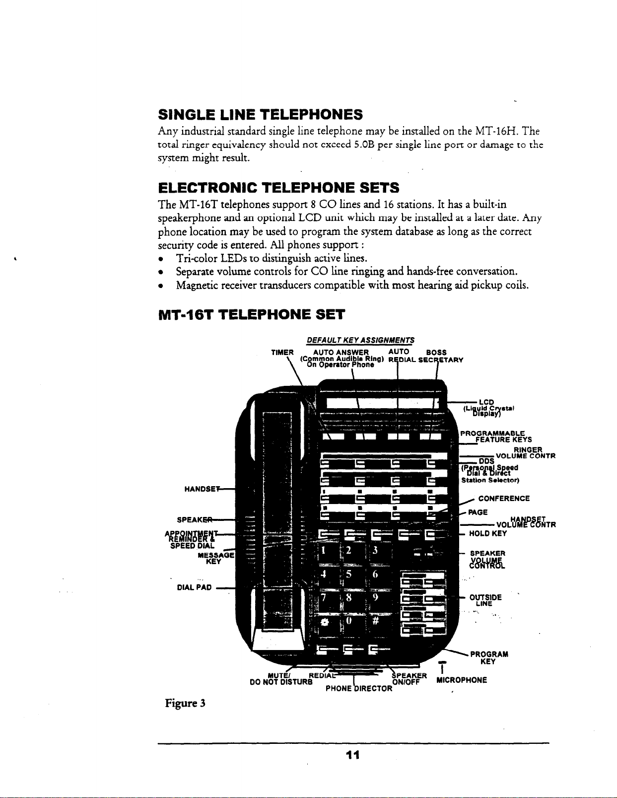
ELECTRONIC TELEPHONE SETS
The MT-16T telephones support 8 CO lines and
speakerphone and an optional LCD unit which may be installed at a later date. Any
phone location may be used to program the system database as long as the correct
security code is entered. All phones support
,
l
T&color LEDs to distinguish active lines.
l
Separate volume controls for CO line ringing and hands-free conversation.
l
Magnetic receiver transducers compatible with most hearing aid pickup coils.
16
stations. It has a built-in
:
MT46T TELEPHONE SET
DEFAULT KEY ASSIGNMENTS
TIMER AUTO ANSWER
(C;~$O&y$,b;o~~Bb
\
\
AUTO
R ETARY
BOSS
t-
LCD
(Liayjd ,Crystal
HANDSEF-
SPEAK-
. .
DIAL PAD -
Figure 3
-VOLUME CONTR
I~
3DS
, CONFERENCE
I
c PAGE
- VOLH##?&R
HOLD KEY
SPEAKER
RINGER
t
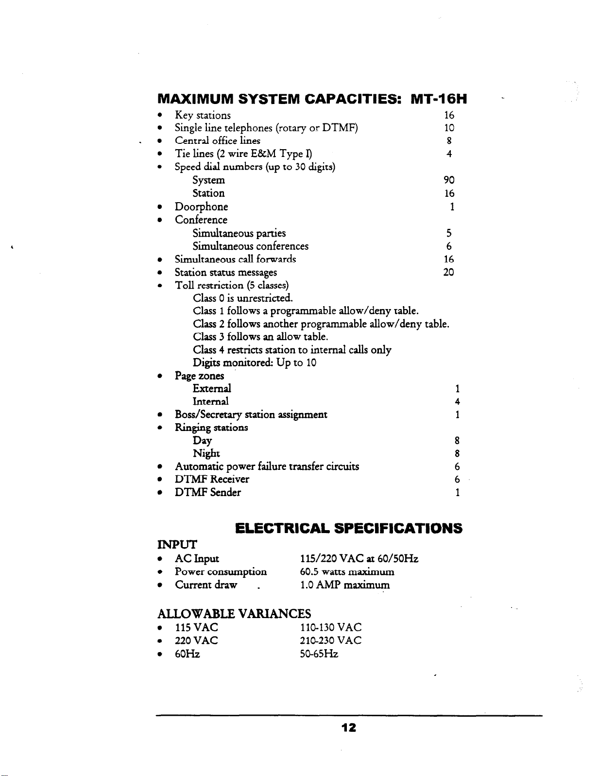
MAXIMUM SYSTEM CAPACITIES: MT-1661
Key stations
Single line telephones (rotary or DTMF)
Central office lines
Tie lines (2 wire E&M Type I>
Speed dial numbers (up to
30
digits)
System
Station
Doorphone
Conference
Simultaneous parties
Simultaneous conferences
Simultaneous call forwards
Station status messages
Toll restriction (5 classes)
Class 0 is unrestricted.
Class 1 follows a programmable allow/deny table.
Class 2 follows another programmable allow/deny table.
Class 3 follows an allow table.
Class 4 restricts station to internal calls only
Digits monitored Up to 10
Page zones
External
Internal
Boss/Secretary station assignment
Ringing
stations
Day
Night
Automatic power failure transfer circuits
DTMF Receiver
DTMF Sender
16
10
8
4
90
16
1
5
6
16
20
1
4
1
8
8
6
6
1
-
ELECTRICAL SPECIFICATIONS
INPUT
l
ACInput
l
Power consumption
l
Current draw
_
ALLOWABLE VARIANCES
l
115VAC
l
220 VAC
l
60Hz
115/220 VAC at 60/5OHz
60.5 watts maximum
1 .O AMP mazimum
110-130 VAC
210-230 VAC
50-65Hz
12
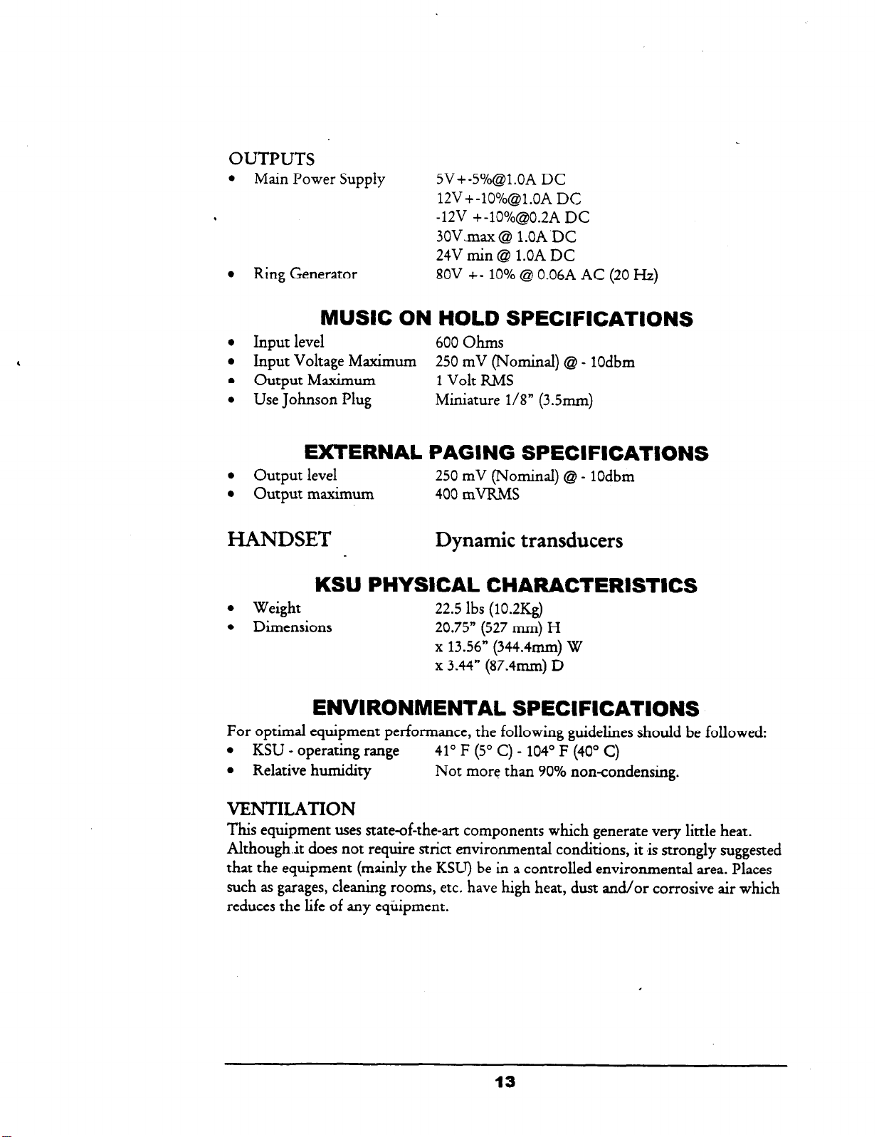
OUTPUTS
l
Main Power Supply
.
l
Ring Generator 80V +- 10% @ 0.06A AC (20 Hz)
SV+-S”/&l.OA DC
12V+-lO%@l.OA DC
-12V +-10%@0.2A DC
3OVmax @ l.OA DC
24V min @I l.OA DC
MUSIC ON HOLD SPECIFICATIONS
l
Input level
l
Input Voltage Maximum
. Output Maximum
l
Use Johnson Plug
600 Ohms
250 mV (Nominal) @ - 1Odbm
1 Volt RMS
Miniature l/8” (3Smm)
EXTERNAL PAGING SPECIFICATIONS
l
Output level
l
Output maximum
250 mV (Nominal) @ - 1Odbm
400 mVRMS
HANDSET Dynamic transducers
l
Weight
l
Dimensions
KSU
PHYSICAL CHARACTERISTICS
22.5 Ibs (10.2Kg)
20.75” (527 mm) H
x 13.56” (344.4mm) W
x 3.44” (87.4mm) D
ENVIRONMENTAL SPECIFICATIONS
For optimal equipment performance, the following guidelines should be followed:
l
KSU - operating range 41’ F (5” C) - 104’ F (40” C)
l
Relative humidity
VJDJTILATION
This equipment uses state-of-the-art components which generate very little heat.
Although.it does not require strict environmental conditions, it is strongly suggested
that the equipment (mainly the KSU) be in a controlled environmental area. Places
such as garages, cleaning rooms, etc. have high heat, dust and/or corrosive air which
reduces the life of any equipment.
Not more than 90% non-condensing.
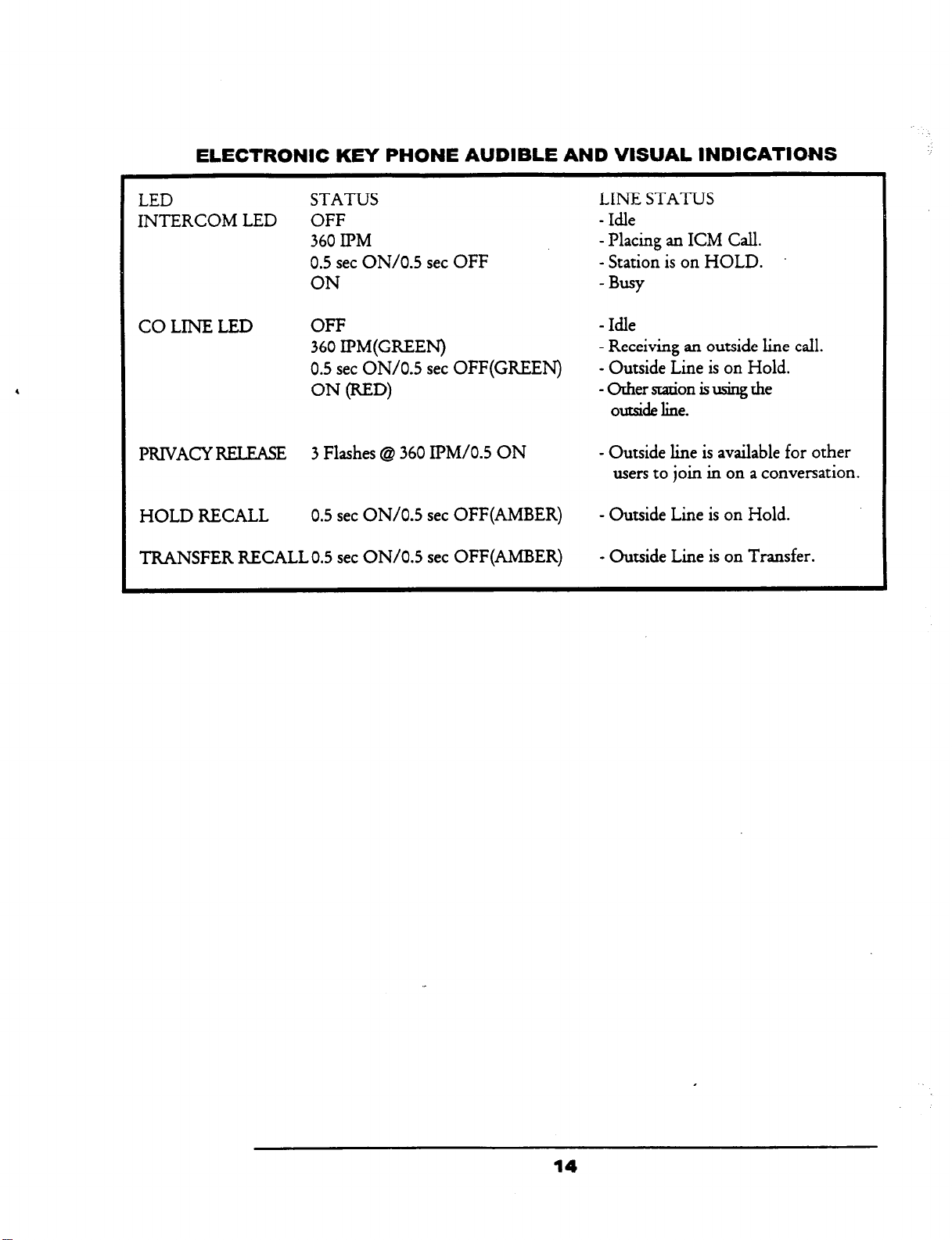
ELECTRONIC KEY PHONE AUDIBLE AND VISUAL INDICATIONS
LED
INTERCOM LED
co
LINE LED
PRIVACYRELEASE
HOLD RECALL
TRANSFER RECALL 0.5 set ON/O.5 set OFF(AMBER)
STATUS
OFF
360 IPM
0.5 set ON/O.5 set OFF
ON
OFF
360 Il?M(GREEN)
0.5 set ON/O.5 set OFF(GR.EEN)
ON (RED)
3 Flashes Q 360 IBM/O.5 ON
0.5 set ON/O.5 set OFF(AMBER)
LINE STATUS
- Idle
- Placing an ICM Call.
- Station is on HOLD.
-
Busy
-
Idle
- Receiving an outside line call.
- Outside Line is on Hold.
-0thersmionisusiugthe
outside line.
- Outside line is available for other
users to join in on a conversation.
- Outside Line is on Hold.
- Outside Line is on Transfer.
14
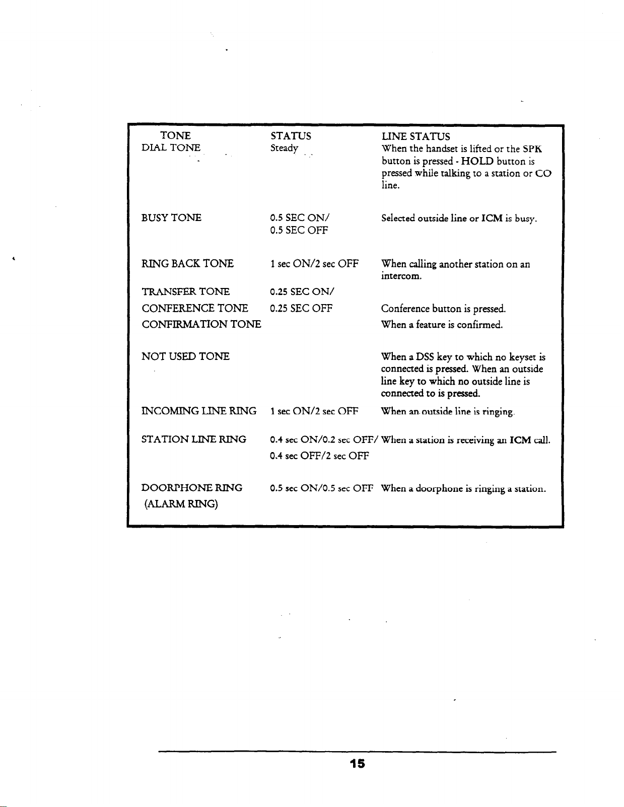
TON-E
DIAL TONE
STATUS
Steady
LINE STATUS
.
When the handset is lifted or the SPK
button is pressed - HOLD button is
pressed while talking to a station
line.
or CO
BUSY TONE
KING BACK TONE
TRANSFERTONE
CONFERENCE TONE
CONFIRMATION TONE
NOT USED TONE
INCOMING LINE KING
STATION LINE KING
DOOKPHONE KING
(ALARM KING)
0.5 SEC ON/
0.5 SEC OFF
1 set ON/2 set OFF
0.25 SEC ON/
0.25 SEC OFF
1 set ON/2 set OFF When an outside line is ringing.
0.4 set ON/O.2 set OFF/ When a station is receiving an
0.4 set OFF/2 set OFF
0.5 set ON/O.5 set OFF
Selected outside line or ICM is busy.
When calling another station on an
intercom.
Conference button is pressed.
When a feature is confirmed.
When a DSS key to which no keyset is
connected is pressed. When an outside
line key to which no outside line is
connected to is pressed.
When a door-phone is ringing a station.
ICM call.
15
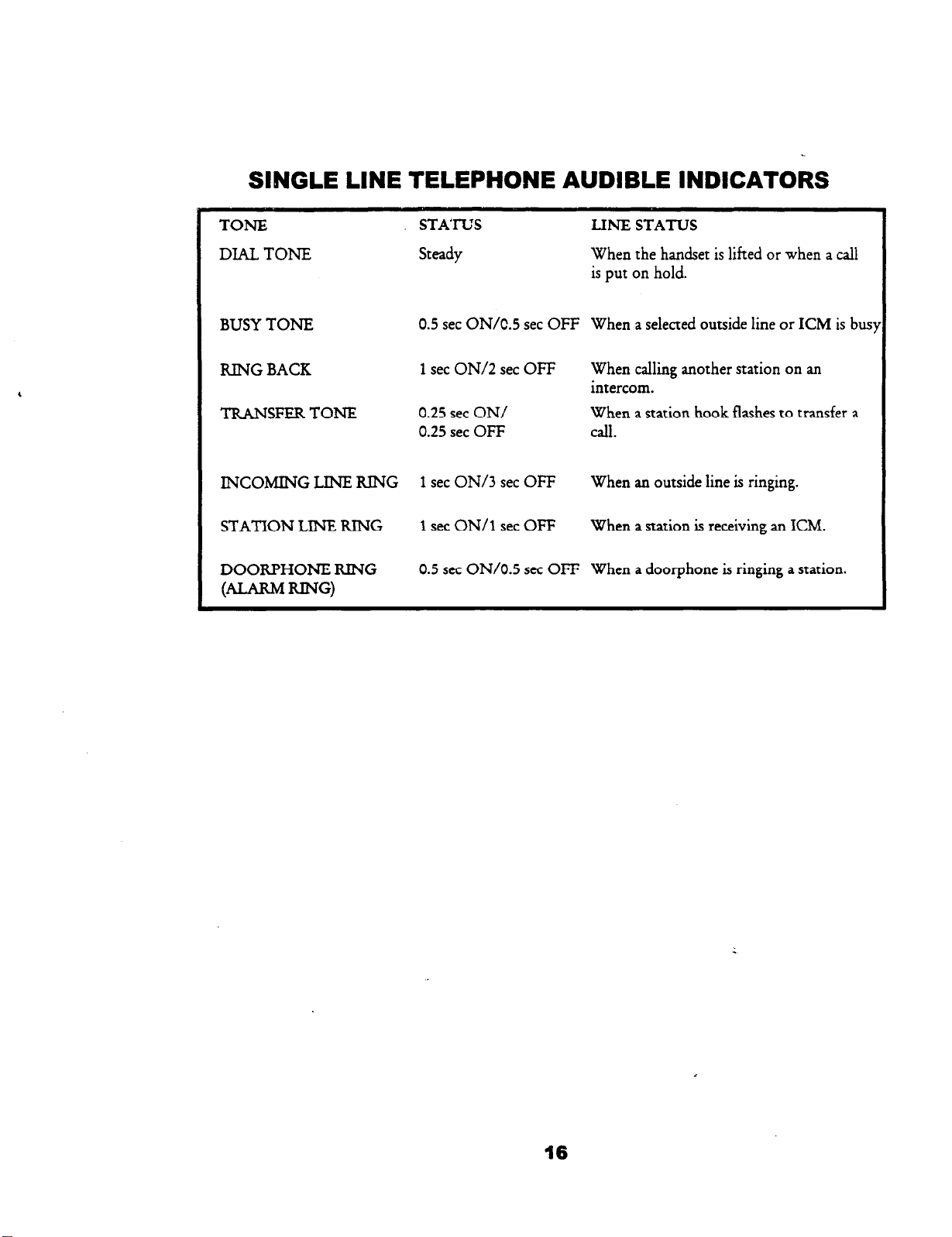
SINGLE LINE TELEPHONE AUDlBLE INDICATORS
TONE
DIAL TONE
BUSY TONE
RING BACK
TRANSFER TONE
INCOMING LINE KING
STATION LINE RING
DOORPHONE KING
@=KMKING)
STATUS
Steady
0.5 set ON/C.5 set OFF
1 set ON/2 set OFF
0.25 set ON/
0.25 set OFF call.
1 set ON/3 set OFF
1 set ON/l set OFF
0.5 set ON/O.5 set OFF
LINE STATUS
When the handset is lifted or when a call
is put on hold.
When a selected outside line or ICM is bus:
When calling another station on an
intercom.
When a station hook flashes to transfer a
When an outside line is ringing.
When a station is receiving an ICM.
When a doorphone is ringing a station.
16
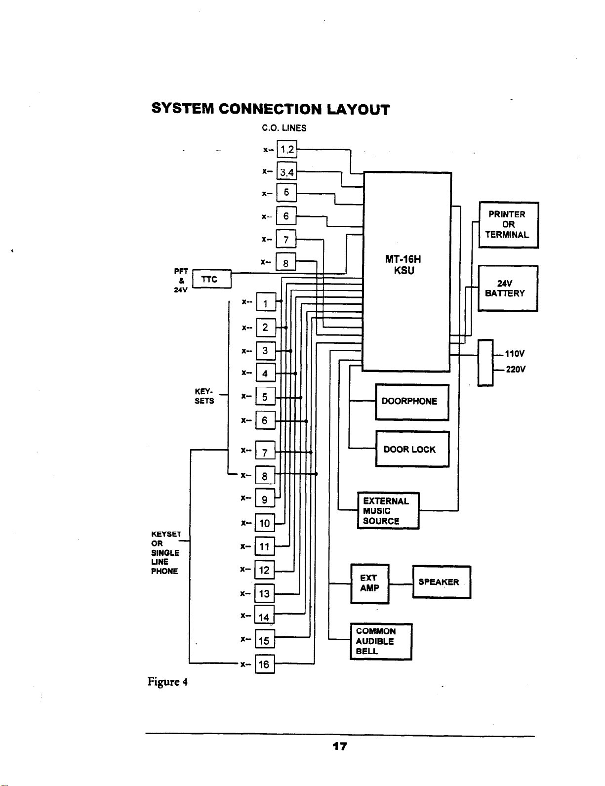
SYSTEM
24V
KEYSETS
CONNECTION LAYOUT
C.O.
LINES
PRINTER
OR
TERMINAL
El
MT-1 6H
KSU
24v
BAllERY
P
KEYSET
OR -
SINGLE
LINE
PHONE
Figure 4
L
EXTERNAL
MUSIC
-I
x-
10
EP
x-
11
cl--
x- 12
II-
+3J-J
x- 14
&Ii
+J---
L
X-pJ----
1
[SOURCE 1
COMMON
AUDIBLE
BELL
17
I----
Section
Mlkl6H FEATURE .DESCRIPTIONS
4-
Account Code ****
All Call Paving
Alphanumeric Disnlav
AuDointment Alert
Assienable DND***
Atten&nt CampOn
Attendant Direct Access
Attendant Recall **
Non-verifiable account codes can be entered while on an
outside call. A maximum of
including [*] and [#I.
A station user can page all stations simultaneously by
pressing his or her own DSS key.
An LCD kit is available to be installed on a phone. The display is
16 charaaen.
The user can program his or her own phone to remind
themselves of an event with a series of tones at a
predetermined time.
The Do Not Disturb feature can be allowed or denied on a per
station basis.
The attendant can camp a call on to a busy station.
Station users have direct access to the attendant simply by
pressing a DSS key or dialing [O].
When the hold/exclusive recall timer expires, the
attendant recall timer will start and the user’s phone will
recall for 30 seconds before retailing to the operator.
12
digits can be entered,
Automatic Hold
AutomaticPauseInsekm
Automatic Privacy
Automatic Recall
Automatic Redial
AutomatkTnmkOwuing
While on an outside line, the user places it on hold
automatically by pressing a DSS key or the PAGE key.
A pause is automatically inserted when using the redial
feature to ensure that a dial tone is present before the
system dials the telephone number.
All outside line calls are private.
A transferred call automatically recalls the originating
station after a period of time.
The system will automatically redial a busy telephone
number up to 3 times at 45 second intervals (up to 99
attempts**).
The system will automatically call a user’s station when
the line that he or she has queued on becomes free.
19
Background Music
Music can be played through the speaker
it’s not in use.
of
a user’s phone while
Batters Backup, Memorv
Batters Backm, Svstem
Boss/Secretarv Hotline
Built-in Directory
Busy Lamv Field
Busv Station Callback
Call Forwarding
CallPickw.ICMandCO
Systemand~programming
power failunz.
The system can continue processing calls during a power failure
(optional).
A hotline can be set up between a boss and a secretary. If
the boss activates the Do Not Disturb feature, all
intercom-calls are forwarded to secretary.
A directory holder comes with each phone to display
important numbers to the user.
A user can tell when another user is busy by observing
the status of the LED on the DSS keys of his or her
telephone.
A user can queue onto a busy station and be called
when the station
Users can forward their intercom calls to another station
(ICM, line or both**).
A call can be picked up from your phone even though it
may be ringing
becomes available.
on
someone else’s phone.
is safe even during an extended
back
Call Offering
Call Offerine Alert**
BWv/NoAn!m!r
CO Flash Cambilitv
CO Line PickuD
Allows you to notify a busy station of another call.
After Call Offering has been activated, a repeated tone is
provided to the called party each time the DSS key is
pressed.
Astationusercancampacallontoastationthatisbusyor
does not answer. The user can also campon to the busy station
sothatwhenthecalledpartyhangsupornznuns
thecallingstationis&rted.
The system is capable of sending an-adjustable flash for
PBX and CENTREX features.
An outside line can be picked up wirh a dial code, even if
it doesn’t appear on your phone.
to his phone,
.
20
-
Common Audible Ring’”
This feature allows the system to direct incoming calls to
a bell, in addition to their normal day/night ring
assignments.
.Up to 5 parties can be conferenced together in any
combination of outside lines and inside parties.
Conference Reioin*%%
Date/Time Disdav*
IMI%i!mrMMF........................................
Dial 9 Groq
Dial 7 Groue**
DisvlavDialin~NumbeF
Disdav Message
Caller Numbe+
Direct Station Selection
The originator of an unsupervised conference can rejoin
the conference.
The optional LCD kit displays time and date when the phone
isnotinuse.
The system will operate with dial, pulse or DTMP lines.
Outside lines to be accessed by dialing 9 can be specified.
Outside lines to be accessed by dialing 7 can be specified.
The LCD displays the telephone number you have dialed,
even speed dial numbers.
The LCD displays the intercom number and name of the
station that is calling you.
The LCD will display the station number that left you a
message waiting.
Wait indication.
You may place an intercom call with the touch of one
button (DSS) or by dialing extension
21- 36.
DISA’*”
.
iWanirrpT_
Discrimidatine Rineing
Doorohone
Door Release Relay
An outside caller can talk to an internal party or, with a
password, access an outside line to place a call.
During external call forward, unsupervised conference and
DISA calls, a warning tone is heard 15 seconds before the
line is disconnected. At that time, the user can override
the disconnection.
Intercom ringing and outside line ringing are different for
ease of identification.
The MT-16H system has one door-phone circuit (standard
on the main PCB).
Allows the user to open a door lock:
21
Do Not
Disturb
A user may stop intercom calls to his or her station with
the do not disturb feature.
DTMF Muting
.
DnvFan‘IialdP
_.-
The system can be programmed so the user does not have
to hear the DTMF.tones.
w users may now perform a screened transfer into a
voice messaging system and enter the required digits for
a specific mailbox’s personal greeting before hanging up.
DTMF Over Pa&*’
A DTMF tone can be sent over the page circuit for
special paging applications.
Tri-color CO LEDs***”
DualI.melPassword9**
Tricolor LED’s help the user keep track of calls.
Two passwords are available, one for system
programming and one for user programming.
E&M Trunks
The system supports 2-wire E&M Type 1 Tie lines (up to
4 max).
Exclusive Hold
A call can be put on exclusive hold so that only the
station that put the call
on
hold can retrieve it.
Specially classed stations are able to intrude into existing
telephone conversations.
EXtCIAGllForwvding
Grouo Listenine ***
Hands-free Answerback
The system can be programmed to forward incoming calls
to another outside location.
Outsidelinescanbepmgmmmedtoringatdifferentphonesin
thesysrem
While on an outside call, the outside party’s voice can be
heard from the speaker of the telephone.
A user can respond to an intercom call without touching
his phone.
Through programming, the speaker key operates the
hookswitch control when a headset is installed.
Distinctive LED flash rates make it easy to see which lines
are in use and which ones are holding.
Multiple stations arranged to receive incoming calls may be
programmed to allow the distribution of inbound calls in a
&c&r hunt fashion
Interface for External
Music
.
Source
, -
A music source may be installed for music on hold and
background music.
An internal music source is standard. External music
requires a customer -supplied music source.
Illtef&forEjdemaPaging
Internal
Page Zones”**
IstNlEnber~l~
Line Oueuine Callback
tiV&MVXM
Meet Me Pape***
MessaPe Waiting
Music On Hold (Internal)
An external page network can be set up for areas such as
large warehouses.
A station can be a member of one of three page zones and
all call pages.
The last number dialed may be redialed with the press of
one button.
A user can queue onto a busy outside line and then be
called back when it becomes available.
The MT-16H was designed to work with the MacroVoice
h4VX Series.
The paged party may answer the caller from any phone
by dialing a code. An outside line may be processed with
the Meet Me Page feature.
A station may leave an indication on another station’s
phone to alert the user that they need to speak with them.
An internal music source is provided for music on hold.
Music on Hold External)
Micrwhonc Mute
Nieht-Transfer
Off-Hook Sipnaling
With an external music source, callers placed on hold can
listen to either radio or taped music.
The speakerphone microphone can be muted so the
calling party cannot hear the user.
Different stations can be programmed to ring in day and
night mode.
Theattendantcanredirxtringingas+me.ntsbyac&&ngnight
tlansfer.
The MT-16H can be configured with or without privacy
on the CO lines to meet the customer’s needs.
Whilebusyonanotherc&atonealmstheuserofanothercaU
ringingin.
23
ovtional class
of service
After normal business hours, the operator may set a
master instruction which reassigns-all stations-into a tollrestricted class of service. (Stations are unaffected**)
Various levels of outgoing call restrictions are
programmable on a per station basis
A user may select an outgoing line before lifting the
handset and the speaker turns on automatically.
Prime Line
Privacv Release
Private CO line
ProasiwScumdCall**
Pmemxdkl?mlinK
Proenmrmble Timing
Pvyneters
Recall Disolav 0555
Recall Identification*
The user can choose between either an automatic outside
line or an KM when the handset is lifted.
Privacy on outside lines may be released to allow other
users to join your conversation.
Anoutsidelinemaybemadeprivatebydenyingallotherusers
aafsstoit.
This feature allows a station to more efficiently process
calls by eliminating the need to go on hook to complete a
transfer.
Many features may be programmed under the DSS keys.
Many timers, such as the hold recall timer, are
programmable to meet the user’s particular needs.
Recalls to display the station users, identified as H
RECALL and T RECALL.
From a display set, any returning calls from the transfer
condition will indicate the type of call and station
involved in the original transfer, such as a hold recall and
a transfer recall.
. .
Rmfznu?JiucM~
Save Last Number Dial
A user can choose between having to press the line key to
answer a ringing line or answer simply by lifting the
handset.
This feature enables the user to change from pulse dialing
to DTMF tone sending while dialing a telephone number.
(Very important for voice mail applications).
This feature enables the user to store a number, which
may be frequently dialed within the course of a day, and
retrieve this number for dialing at any time.
24
 Loading...