

Page 1

User manual
Akaba – New Concept
for Casablanca Avio, Prestige and Kron
Page 2

Safety notices
To avoid making mistakes during operation, we recommend that you carefully follow the
instructions provided in this manual.
We would also like to point out that Akaba – New Concept has been designed with the hobby
enthusiast in mind.
We have taken a great deal of care while programming and checking this software.
Nevertheless, since it is not possible to guarantee totally error-free software applications in all
environments and at any time, we unfortunately cannot rule out the possibility that some errors may
have crept in. If, contrary to all expectations, this is indeed the case, we shall remedy any errors in
the program and supply the affected customers with the new software free of charge. We cannot,
however, accept any liability for loss of data/time or any consequential damages that may occur as
a result, particularly since we have no inuence over correct software installation and operation by
the customer. MacroSystem Digital Video AG and its dealers therefore cannot be held liable for any
defects or unintentional damage in connection with the installation or use of Akaba – New Concept.
MacroSystem Digital Video AG and its dealers do not guarantee error-free use of the software or
complete awlessness of the program.
Any implied guarantee is null and void, including guarantee of suitability of the software or
operating instructions for a particular purpose.
Neither MacroSystem Digital Video AG nor its dealers are responsible for any damages resulting
either directly or indirectly through the use of the software or the operating instructions, e.g. for
prot loss, costs, hardware or software problems or other issues.
Page 3

Contents
Page
1. General............................................................................................................... 5
1.1 General................................................................................................... 5
1.2 What is Akaba – New Concept? ........................................................... 5
2. Installation and Starting the Program ............................................................. 7
3. Operation ........................................................................................................... 9
3.1 Operation controls ................................................................................ 9
3.1.1 General buttons ........................................................................ 9
3.1.2 Palette, pencils & brushes........................................................ 9
3.1.3 Tools........................................................................................... 10
3.1.4 Editing functions....................................................................... 11
3.1.5 General ...................................................................................... 14
3.2 Margin areas.......................................................................................... 15
3.3 Display ................................................................................................... 15
3.4 Notes on the Power Key Option .......................................................... 15
3.5 Individual buttons / functions .............................................................. 15
3.5.1 Palette ........................................................................................ 15
3.5.2 Pencils & brushes ..................................................................... 16
3.5.3 Fill options................................................................................. 17
3.5.4 Mask........................................................................................... 18
4. The Three Operating Modes ............................................................................ 19
4.1 Draw mode ............................................................................................ 19
4.2 Retouch .................................................................................................. 19
4.3 Gamma .................................................................................................. 20
5. Application Examples ....................................................................................... 21
5.1 Setting sun............................................................................................. 21
5.2 Retouching a distorted image ............................................................. 23
5.3 Partial brightness correction................................................................ 25
5.4 Title with transparency gradient.......................................................... 27
5.5 Cutting out a brush............................................................................... 29
Page 4

Page 5

5
1. General
1.1 General
Thank you for buying Akaba – New Concept!
We thank you for your trust and hope that this
product will meet your expectations.
Akaba – New Concept will let you get more use
out of your Casablanca than ever before.
We are at your disposal for any questions or
suggestions you may have.
You will nd addresses and telephone numbers
in the Casablanca manual.
undesired elements. You will nd special copy
stamps in addition to the normal drawing tools.
Gamma lets you correct brightness, contrast,
saturation, RGB, etc. - and not just for the entire
frame, but also separately for self-dened areas,
even with variable intensity.
For example, say the image in the lower area is
too dark, but the sky is appropriately exposed.
Normally the video would be unusable, but
correcting it is no problem for the mask function
of Akaba – New Concept (see application
example 5.3 Partial brightness correction.).
Akaba – New Concept saves all settings, pencils
and brushes for each of the three operating
modes.
Please have your device’s serial number or your
customer number ready when contacting us.
1.2 What is Akaba – New Concept?
Akaba – New Concept is a completely new
program for manually editing single frames or
video scenes. You can retouch, modify or extend
your own individual frames in many ways.
Three different operating modes give Akaba a
wide range of possiblities that are easy to use
and implement.
Draw mode (drawing and animation mode)
features all the usual possibilities for drawing.
Lines, circles, polygons and surfaces can
be drawn with widely varying pencils and
attributes. You can create graphic images or
extravagant titles. The drawing you create can
be moved during the course of the scene, (as is
done in the program PIP Studio).
Retouch lets you select and manually edit each
individual scene frame. The supplied tools let
you easily conceal small dropouts or other
Page 6

6
7
Page 7
7
2. Installation and Starting the
Program
In order to install Akaba – New Concept you will
need the SMART EDIT system software (at least
version 2.3).
The system version is displayed in the
information eld of the System Settings menu
(lower left).
Leave your Casablanca turned on and select
the Install Product button in System Settings.
After the corresponding window has appeared,
insert the installation SmartMedia card into the
Casablanca SmartMedia reader so that the gold
contacts are facing down and the folded corner
is pointing forward to the left (in the direction of
the Casablanca).
function representations and descriptions in
this manual may differ slightly from the actual
software.
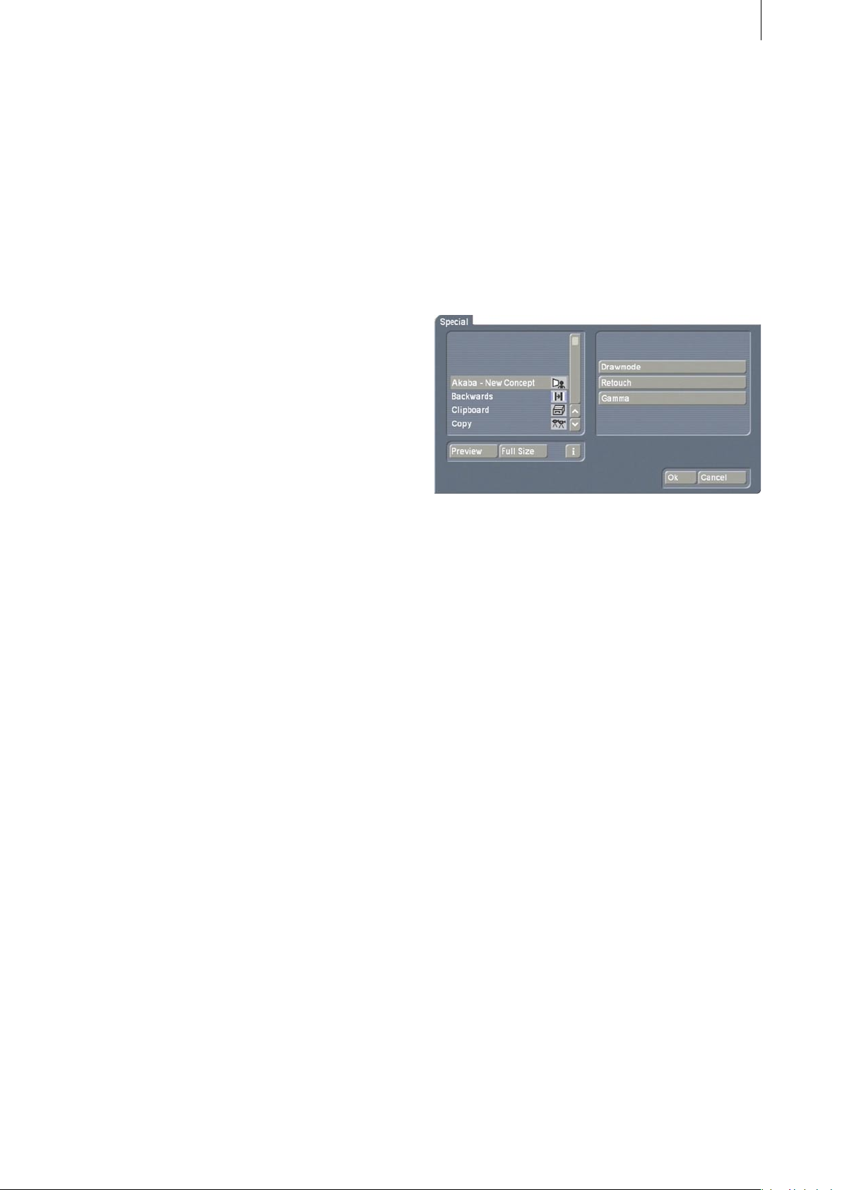
After you have installed Akaba – New Concept,
you will see it listed alphabetically in the Edit
menu under Special. After selecting Akaba
– New Concept you will see the three possible
operation modes displayed to the right (effect
options):
After you have inserted the card, you will see the
software Akaba – New Concept displayed in the
window. Select it in the list and click on Activate.
A number block is displayed for entering the
enable code you have obtained from your
dealer. After that, a message is displayed
indicating that installation is nished. You can
then remove the SmartMedia card.
If you want to install the program as a demo
version, click Activate, and then click Cancel
in the number code window. The word demo
now appears after the program name. Click on
OK to close the window and then remove the
SmartMedia card. Akaba – New Concept is now
installed as a demo version.
Notes on other products:
Akaba – New Concept supports the Power
Key option. Separate instructions for keyboard
control of this program are not available - press
the F2 key to see the possible key abbreviations.
Read also section 3.4 Notes on the Power Key
option.
You initiate a mode by clicking on the
corresponding button.
Akaba – New Concept always operates on the
activated scene in the scene bin. As long as the
same scene is always active when the program
starts, Akaba – New Concept automatically
saves all modications so that you can always
continue your interrupted work.
If you select a scene other than the scene that
was active during your previous session with
Akaba – New Concept, then the system warns
you that if you continue, all changes made to the
previous scene will be lost. With Cancel you can
prevent this and then select the previous scene.
Within a scene you can switch among the three
modes Draw mode, Retouch and Gamma.
Akaba – New Concept saves all three modes
independently of each other. The most recently
used mode is always used for calculation.
Modes are never superimposed!
Note: Because of possible software modication
after this manual has gone to print, some of the
Page 8
8
9
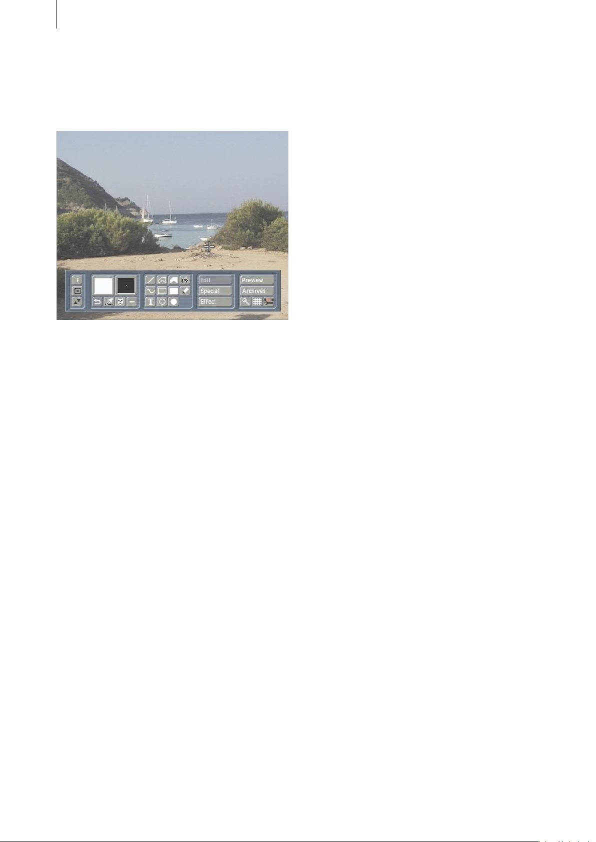
The operation panel is displayed after you have
started the program and selected an operation
mode. You will then see the rst frame of your
video scene in the background.
Page 9
9
3. Operation
This chapter rst discusses the functions
generally available in all three operating
modes. The individual buttons are described in
sequence, and then the differences of the three
operating modes are explained.
3.1 Operation controls
The operation panel of the main menu is divided
into ve subpanels, each of which contains
several buttons and functions.
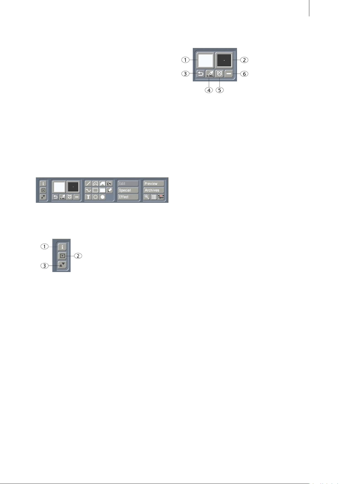
3.1.1 General buttons
3.1.2 Palette, pencils and brushes
1.) Palette
Clicking on this button activates the Palette
window. Akaba – New Concept lets you use
an extended palette allowing a choice of color,
pattern and color gradient. The selected color
and pattern are then displayed within the palette
button. Further details are explained in section
3.5.1 Palette.
2.) Pencils and brushes
Clicking on this button activates the Pencils and
Brushes window. Various predened pencils can
be used (and changed). The currently selected
drawing pencil is displayed in the button.
Brushes you cut out yourself cannot be used for
drawing.
You can nd more information in section 3.5.2
Pencils and brushes.
1.) The Info button opens a window displaying
data on the program version.
2.) This button minimizes the menu panel, as
you already know from Casablanca.
3.) This button is used to move the panel to the
opposite screen edge.
3.) Undo
Clicking on this button causes the previous
drawing operation to be discarded. It is usually
possible to undo several operations, but the
specic number of undoable operations cannot
be known ahead of time because it it determined
by the surface size of previously made changes.
4.) Eyedropper
An eyedropper is used to select a color present
in the frame that can then be used for further
drawing operations. Position the eyedropper
at the desired spot in the video frame and
press the left trackball key. You will see that
the selected color is then displayed in the most
recently active color eld of the palette.
Assuming you have not previously set the
option Solid in the Palette window, the color is
nevertheless used and appears in the Palette
button.
Page 10
10
11
5.) Mask mode
This button is used to switch to mask mode.
You can read more about this powerful tool in
section 3.5.4.
6.) Activate mask
Here you choose whether the current mask
should be used when drawing. If the checkmark
is visible, then the mask is used. If a dash is
visible then it is not used. We recommended
that you use the mask mode after you have
become acquainted with Akaba – New Concept.
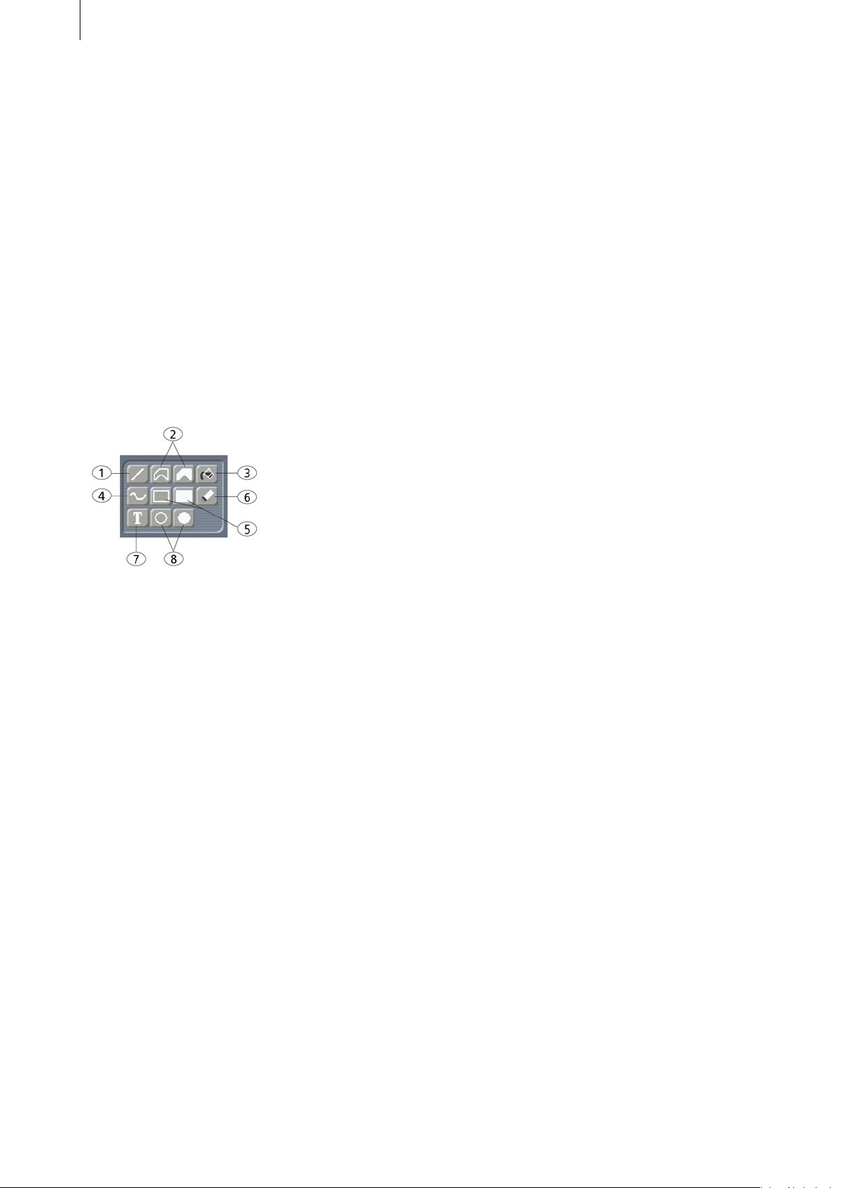
3.1.3 Tools
Optically vertical, horizontal or diagonal lines
(45°) are indicated during drawing by a change
in the trackball cursor (dash next to the symbol).
2.) Polygon (unlled, lled)
Either a lled or unlled closed polygon can
be drawn. Do the same as when drawing a
line; with the rst click you set the start point
and with every additional click you add a line
segment.
To close the polygon and terminate the drawing
operation move the trackball cursor over the
start point. The start point is indicated by a
change in the cursor and you can click to nish
the polygon.
Depending on the pencil, the corner points
may show minor discrepancies during drawing
but will appear correctly after the polygon is
nished.
If you are drawing the polygon with a color
gradient and a selected color, then the polygon
is shown as a single color until it is closed, at
which time the color changes again.
1.) Line
Clicking on this button causes the menu panel
to disappear, allowing you to draw a line in the
video material. A diagonal line segment (45°) is
displayed so that you can precisely position the
line.
The cursor is positioned to the upper-left end
and the point can now be positioned. A click on
the left trackball key sets the start point of the
line.
Now the cursor changes to the other end of the
line and you can set the end point of the line
with a second click.
Clicking on the left trackball key without having
moved the trackball itself causes a diagonal line
(45°) to be set.
In order to freely draw the line simply change
the position of the trackball before you conrm
the end point by clicking on the left key.
During the entire time, the line is displayed as it
will appear using the current pencil and color.
The next line can be drawn immediately after
setting the end point. Clicking on the right
trackball key returns you to the operating panel.
3.) Fill
A certain region of the frame is lled with a color
(like from a paint bucket). This is a complicated
operation that requires you to make several
settings under Fill options in order to obtain the
desired result. More on this in section 3.5.3 Fill
options.
The ll operation is started by clicking within the
desired region. The object is lled with the color
dened in the active “color eld” according to
the ll options you have set.
4.) Freehand
Clicking on this symbol starts the drawing mode.
Move the trackball cursor to the desired start
position and click on the left trackball key.
Do not hold down the trackball key!
Move the trackball to draw under the cursor.
A second click with the left key terminates the
operation.
Large pencils and fast movement might result
in drawing individual points and not continuous
lines.
So don’t move the drawing pencil with the
trackball too quickly!
Page 11

11
5.) Rectangle (unlled, lled)
Drawing is done as with Line. A lled or unlled
rectangle can be drawn by selecting rst the
upper-left and then the lower-right corner. The
cursor changes if the rectangle is optically a
square.
6.) Eraser
By clicking on this button you can delete your
drawings in the video frame. The currently
selected pencil is used. The video background is
not affected.
Operation is the same as described for the
Freehand tool.
The thickness of the eraser depends on the
current alpha value for the pencil color. An
alpha value of 100% causes everything under
the eraser to be removed. Smaller alpha values
result in only a partial erasure.
7.) Text
Clicking on this well-known symbol calls up
the Casablanca text-entry menu. The text
created with the titler is inserted into the Akaba
– New Concept drawing with all panels and
backgrounds. Only one page is supported.
Effects are not supported.
After the text has been inserted into Akaba –
New Concept, it is a normal part of the drawing.
If the titler is activated again, it contains the
most recently entered text, which can be
deleted or modied, but does not change the
text already inserted into Akaba. Modication
is possible only if you delete the text with Undo
immediately after inserting the text, and then
activate the titler again.
8.) Ellipsis
The ellipsis is created in the same way as a
rectangle, but the center point is specied rst,
then the width and height of the ellipsis. If
you have optically drawn a circle, then this is
indicated by the cursor.
Note: If you draw a line, rectangle, or an ellipsis,
the cursor changes form to indicate when any of
the following special cases occur:
• horizontal, vertical or diagonal line (45°)
• a square
• a circle.
But this is different according to screen format
(4:3, 16:9, PAL/NTSC). The program uses the TV
standard. But depending on the setting, there
may be deviations from one TV to another. For
example, a rectangle with equal sides of 100 *
100 pixels is not a square.
3.1.4 Editing functions
1.) Edit
The most recent draw operation can be edited
after having been made. You can roughly draw
an object (line, rectangle, etc ...) and then edit
it in this submenu. You can move the object,
deform it, and/or change the pencil and color.
The Edit button is active if an object has been
drawn, but only if the object is not a freehand
object.
If you click the button after having drawn a
lled or unlled polygon, then you will see
two buttons and a slider bar serving to move
the polygon. By clicking on the Move Polygon
button, you can move the entire polygon
anywhere on the screen and set the nal
position with the left trackball key. The Move
Point button allows you to move just one point
of the polygon on the screen. You can achieve
this also directly in the drawing by moving
the cursor over one of the points. The cursor
changes its form when it is moved over the a
point. The slider bar jumps to the position of the
actual point. Now you only have to press the
Move Point button or click where the cursor has
changed form.
If you have just used another tool to draw an
object and you then click on Edit, you will see
a representation of your drawing tool in the
operating panel (line, circle, rectangle).
In this representation the active points of your
Page 12

12
13
object are marked and you can click on them to
move them in the drawing. To move individual
points or the entire object you can either use
these buttons or click the corresponding point
directly in the drawing.
In the second case the trackball pointer displays
the possible functions.
Note: Some tool functions cannot be edited,
such as Freehand, Fill and Erase.
While a point or all points of a polygon are being
moved, the display will not be exactly correct,
especially if thick, blurred lines are involved. But
after the operation is nished, the display will
once again be correct.
2.) Special
This menu item offers some rarely required
functions and settings.
In the Effect window you rst see the buttons IN
and OUT. The button you click is activated and
is displayed in blue. An active IN button means
that all further settings relate to fading-in the
drawing. An active OUT button means the that
following settings refer to the fade-out.
Under Effect you have the possibility of
choosing fade-in or fade-out from twelve
different effects.
- Clear image
All drawing operations performed are deleted.
In retouch mode this affects only the current
drawing!
- Set image
The entire screen is lled with the currently
selected color. Any drawing operations already
made are lost.
- Fill options
An additional window is called up in which
you have diverse options for the automatic ll
function (see section 3.5.3 Fill options).
- Grid
You can choose the size of the grid for the
drawing functions (see section 3.1.5 General,
Grid).
3.) Effect
Akaba – New Concept encloses the drawing
with an (invisible) frame. This region, i.e.
everything that was drawn, can be faded and
animated with the functions from the program
PIP Studio.
The rst eleven settings work as the name
implies - the setting Custom means that you can
set your own values. If you have chosen another
fade and are doing effect editing, then the
setting is automatically set to Custom.
The button Fade time uses a slider bar to let you
specify the duration of the fade-in or fade-out.
The highest value you can set is the length of
the entire video scene.
For example, if your scene is six seconds long,
then you can choose two seconds for fade-in
and two seconds for fade-out. The remaining
two seconds are calculated as full display time,
i.e. the time the drawing appears in the scene
without a fade effect. After the full display time
elapses the drawing is faded out.
If you set path points during editing (see below),
then the picture position is affected during the
full display time. The last path point of the fade-
in is also the rst path point of the fade-out, and
determines the position of the picture during the
full display time.
The Edit effect button opens a new operating
panel. In this menu you can insert path points
that determine the movement of the drawing.
Page 13

An additional path point is positioned when you
click on Insert. The newly inserted path point
is the active path point, displayed in green.
Inactive points are yellow. The new point is
always inserted in back of the currently active
path point. If the active path point is not the
last one, then it is inserted exactly between the
current and the next path point on the curve (of
course, two path points dene a line segment,
not a curve).
Note: A path-point segment consists of two to
ten path points together, whereby the path point
for the full display time is always displayed as
a large octagon. The drawing moves at steady
velocity from the rst to the last path point of
the curve. If two path points are near to each
other, then the drawing is on the corresponding
curve segment for a shorter time then when the
two points are further apart from each other.
(You should remember this note when you want
to change certain values of the drawing between
path points.)
If two path points exist and one path point lies
exactly on top of the other, then the drawing
does not move. But parameters of the drawing
can still be modied and take effect for the entire
fade time. For example, a fade can be created
at that point. If there are more that two path
points, and one point lies exactly on top of its
neighboring path point, then the rst point has
no duration and is skipped.
Clicking on the Delete button removes the
currently active path point so that the previous
path point becomes the currently active path
point.
Clicking on the Position button causes the active
path point to turn blue. It can now be moved
with the trackball. During this process you can
view the position coordinates at the screen
edges. You conrm the new position with the
left trackball button, or cancel with the right
button.
13
The Position button does not necessarily have to
be used. You can click directly on an active path
point once or on a non-active path point twice
(to make it active) and then drag the path point.
If you would like to put the point outside of the
video frame, then simply by dragging the point
out of the frame causes a representation of the
relevant region beyond the visible surface to
become visible.
The meaning of the path-point colors is
summarized below:
Note: “Interpolation” means the automatic
calculation of values between given control
points.
yellow: a non-active control point without
particular characteristics. Clicking on the point
causes it to turn green (active).
red: a non-active control point for which settings
have been made manually under Edit. This
means that at least one checkmark was set
manually (no interpolation). Clicking on the
point causes it to turn green.
green: the currently active point. The operations
Position, Edit and Delete refer to this point.
Clicking on the point causes it to turn blue.
blue: This point can be dragged to a new
position. After being clicked again the point
turns green.
When you click on Edit, a window appears in
which you can specify the size and the alpha
value of the active path point.
If you click on Size, the window disappears
and the path point becomes active so that its
size can be changed. The size is displayed at
the screen edge. A click on Alpha activates the
slider bar to the side, with which you can set the
transparency value of the drawing between 0
and 100%.
You can disable the buttons Size and Alpha by
clicking on the corresponding check boxes so
Page 14

14
15
that a checkmark appears instead of a dash.
Disabled buttons occur when you have set
intermediate points whose sizes and alpha
values have been calculated automatically using
the start and destination points. The checkmarks
for the rst and last points cannot be reset.
In this case a value must be given because
interpolation is not possible.
If a checkmark is visible, then the value specied
to the left is used at this path point. If a dash
appears, then the corresponding value is
interpolated using the neighboring path points.
The interpolated value is displayed. You can
change the desired state at any time.
If the slider bar is completely lled, then there
currently exists just one path point. If it is
possible to click and move the slider bar, then
there are several path points in your video
material that you may activate. You can use the
individual buttons to the right of the slider bar to
exactly pick one path point after another.
However, if you have chosen a small size or a
small alpha value, then only a green point is
displayed.
The fully displayed drawing may be distracting,
so you should make it visible only to check that
everything is OK.
In this menu it is also possible to see a Preview.
With the Ok button you conrm your settings,
exit the menu and return to the Effect menu.
Here the Preview button lets you see the
preview in a small window. This function lets
you view the preliminary result in this menu.
3.1.5 General
IN/OUT: With these two buttons you can choose
whether your settings refer to fade-in or fade-
out.
Simply click on the desired button so that it
turns blue (active) and is selected.
If you would like to switch from fade-in to fade-
out and make further settings (such as e.g.
changing the fade time or the effect), then you
must go to the Effect window.
Each fade has its own curve and of course its
own parameters. It is important to know that
changing the parameters of the large path point
(last point for fade-in, rst for fade-out) always
affects the large path point of the other effect.
The point displayed in large is the one at which
the drawing stands still during fade-in and fade-
out.
If you click on the dash next to the Image button,
then it is changed to a checkmark (activated).
This means that you now see displayed not only
a green path point, but also your drawing at the
position of the currently active point.
1.) Preview
Here you can let a preview be displayed without
having to exit the program.
2.) Archive
The nished drawing (without video frame)
can be archived and later reused (even in other
scenes). The size of the archive is limited to
about 10 to 12 frames. An attempt to archive
more frames results in a warning message.
3.) Magnifying glass
A magnifying glass can be used whenever you
need to draw precisely. Clicking again on this
button turns off the magnifying glass.
The magnifying glass always shows an are
around the cursor position. You can specify the
magnication (factor 4 to 32) at the lower left. To
the right below you see the cursor coordinates
displayed.
It is also possible to move the magnifying
window to the opposite side of the screen and to
turn off the cross hairs.
Page 15

15
4.) Grid
This button is used to toggle a global grid on
and off. You can set the raster size under Special
(in section 3.1.4 Edit functions). When the button
is active, then all drawing functions operate
on an invisible raster so that you can position
objects at exact distances to each other. This
makes it easier, for example, to position objects
or to create tables.
5.) Menu symbol
Here you exit Akaba – New Concept and return
to the Casablanca Edit menu. Akaba – New
Concept saves all settings so that you may
continue editing later.
3.2 Margin areas
Akaba – New Concept allows you to move
the displayed frame automatically to the side
whenever you hit the screen edge with the
cursor. This lets you work in the otherwise
inaccessible margin areas of the video frame.
roughly position the cursor by pressing and
holding down the Navigation key (to the left of
Ctrl) while you use the arrow keys. You achieve
a ne, pixel-wise movement by simultaneously
holding down the Ctrl and Navigation keys while
you use the arrow keys. This ne positioning is
especially useful when creating tables or exact
vertical lines.
3.5 Individual buttons / functions
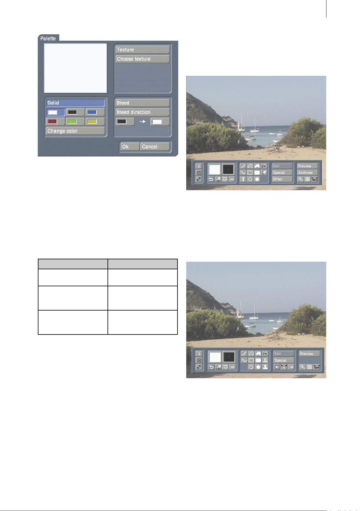
3.5.1 Palette
If you click on the palette button the Palette
window appears. It is divided into the three
areas Solid, Texture and Bleed.
3.3 Display
The video frame is generally displayed as a
half-frame, i.e. line pairs are identical. Drawings
however are displayed in full resolution so that
you can immediately see how the result will
appear (exception: Retouch).
The full-frame display lets you see when
drawing whether the edited video material (e.g.
when using very thin lines) will icker after
calculation.
Of course, after calculation a full-frame version
of the video portion is also made. No resolution
is lost.
3.4 Notes on the Power Key option
Akaba – New Concept supports the Power Key
Option. Pressing F2 displays the available key
shortcuts.
The possibility to position with the help of
the Power Key is particularly useful. You can
You can toggle between these operations by
using the correspondingly named buttons above
in the appropriate area. The currently active
button is displayed in blue. Toggling occurs
automatically when a corresponding control is
selected.
The preview window at the upper left displays
the currently selected result.
Note: After initial installation of Akaba – New
Concept, no texture has yet been selected. When
you click for the rst time on the Texture button
in the Palette window, an image pool is called
up from which you can select a texture.
After you have selected a texture for the very
rst time, the Texture button toggles the preview
Page 16

16
17
window. You now access the image pool with
the Choose texture button.
- Solid
At rst you can select one of the six color elds
so that it is easy to switch frequently between
the colors used most often. The button Change
color is used to dene a new color. Clicking
on Ok in the color box causes the color in the
current color eld to be replaced with the color
you have just dened.
- Texture
You use the Choose texture button to call up the
image pool from which you can select a texture.
- Bleed
Here you can set a color gradient, such as is
also possible in the image pool. In addition,
you can specify a direction by clicking on Bleed
direction. You specify the direction by setting a
helping line in the video image. This enables the
direction to be adapted to certain parameters.
Any color and alpha transparency can be used
for the beginning and end color.
3.5.2 Pencils and brushes
This window brings together pencil selection
and work with brushes. It is divided into four
areas:
- Pencils
Pencils are used for the various drawing
operations. Some predened pencils are offered
(four square and four round) whose size and
sharpness can be set.
After selecting the desired pencil, you close the
window by clicking on Ok.
- Brushes
Akaba – New Concept supports three brushes
that can be used independently of each other. As
soon as a brush has been selected, the operating
controls and enabled:
Cut
In the second button row you will nd three
possibilities to cut a brush out of the frame:
rectangle, ellipse or polygon. These functions
are carried out analogously to the corresponding
draw functions, but do not change the image
content.
The cut-out brush is displayed in magnied form
in the preview area (below right). The preview
shows the brush in original size, if possible. If
the brush does not t into the preview area, then
it is reduced in size, and this is indicated by an
inserted magnifying-glass symbol.
Immediately after being cut out the brush is
given the blur that has been set. This value
can be changed at any time. For real video it is
usually important that the brush has some blur
in order to create a realistic impression without
a sharply dened edge.
Mode
Here you choose whether the brush is cut out
only from the data of your drawing (Image) or
from the drawing and the background video
image (Image & Video). Please note that the
vertical resolution of the video frame (not the
resolution of the drawing) is halved.
Edit
With the help of these three buttons the current
brush can be rotated 90° to the right (more
than once: 180°, 270°), and mirrored either
horizontally or vertically.
Page 17

17
- Attribute
Pencils and brushes can be changed in this
subpanel. For all changes, even concerning the
brushes, there is no additional quality loss when
different functions are used repeatedly.
Technical note: The brushes remain stored in
the background in their original size and are
used as a basis for different actions (e.g. when
reducing in size). In this way full quality is
guaranteed (e.g. after a renewed magnication).
Blur
It is recommended to always work with a little
blur (e.g. 10-20%) in order to attain softer forms
that can be displayed well on a television set,
especially for video editing.
Width
Here the complete size of pencils is determined.
Pencils are always round or square.
The complete brush size can be changed (Lock
aspect on) or only the width can be changed
(Lock aspect off).
is not possible. In this case you should use the
pencils.
Ok
After selecting a pencil you usually exit the
window with Ok so that you can use the pencil.
You again see the operating panel, and you can
select a tool.
Cancel
Most of the changes (pencil or brush selection,
attributes, ...) made since the Pencils & Brushes
window was opened are undone when you click
on Cancel. Cut-out brushes and any stamps in
the video, though, remain as they are.
3.5.3 Fill options
Filling surfaces in video frames is very difcult
because there are only uid transitions and no
explicit borders. Because of this, it is necessary
to set a number of different parameters
(threshold values) to obtain acceptable results.
Height
For brushes the height can be set independently
of the width when the Lock aspect button is
deactivated.
Lock aspect
This mode can be set only for brushes. Normally
this function should always be on so that the
aspect ratio of cut-out objects remains the same
in all cases. In special cases it can be shut off so
that width and height can be set independently
of each other.
- Preview
Here you obtain a preview of the active pencil/
brush with the current settings (e.g. blur, mirror).
Stamp
With this button (at the lower window edge)
you close the window and stamp the brush (or
pencil) one or more times directly into the video
frame. By clicking the right trackball key you
come back to the window Pencils & Brushes.
Painting (line, circle) with self-made brushes
- Color
In order that lling continues from the start
position, the color replaced with the ll color
must agree with the start color to the degree
given by this parameter. For 100% the colors
must be identical, for 90% there can be minor
differences between the colors. For a setting of
0% the color is ignored.
- Hue
Setting the hue is done in the same way as with
setting color.
- Alpha
Here the alpha value (transparency) is important.
Page 18

18
19
For this function the button Reference (see
below) must be set to Image, because only
those drawings you have made yourself can
have an alpha value that deviates from 100%. If
you ll your object after you have selected an
alpha value, the object is only lled to a certain
percentage (the alpha value) with the active
color. For every click you obtain a different color
intensity.
- Reference
Here you have the choice between two options.
If you have set Image, only the drawing
operations made are considered, i.e. the video
picture is ignored. In contrast, the mode Image
& Video takes account of both the drawing and
the video.
The reference can only be switched in Draw
mode. For Retouch it affects the unity of
drawing and video, because separate work is not
possible.
Note: It may happen that, while a black object
in your video material is being lled, another
black object is also lled. The reason for this is
that the video frame is surrounded by a black
frame that you can see if you move the screen
cursor outside of the video material (see section
3.2 Margin areas). The black frame connects the
objects contiguous with it in your video material.
3.5.4 Mask
One thing gives Akaba – New Concept
additional possibilities. A mask is supported
for practically all operations. This gives you
the possibility to restrict drawing operations to
certain, freely denable picture regions. You can
even specify how strong an effect should be at a
given position.
The mask appears in gray on top of the video
picture. The greater the amount of gray, the
more the video picture is overlaid (masked) and
the weaker the drawing operations will be. No
changes will be possible where gray completely
hides the video picture. The clearer the video is
(the gray mask is more or less transparent), the
more visible the drawings will be.
You can use several masks, even while you are
drawing, because the mask is used only for
drawing.
The following table presumes that the Show BG
function (see below) is deactivated.
Mask mode
The video picture is
completely visible.
The video picture
is covered with an
opaque, gray mask.
The video picture can
be seen through the
half-transparent gray
mask more or less
clearly.
Drawing tools
The most frequently used drawing tools can be
used as usual when drawing the mask.
Transparency
In this window, which you recognize as the
Palette window from the other menus, you can
specify the mask transparency.
Draw mode, Retouch,
Gamma
All operations are
completely visible.
No further drawings
can be made.
Drawing operations
are weakened (depending on the level of
mask transparency).
The mask is xed, i.e. not connected with
movement in the course of the video scene. A
mask can be drawn in mask mode.
Page 19
You can set the transparency of the mask with
one of the predened six gray levels. In addition,
you can modify the gray value with values of 0
to 100 using the Change Transparency button.
The following table describes how the mask
transparency is displayed according to the gray
levels.
19
4. The Three Operating Modes
4.1 Draw mode
In this mode you will nd all buttons and
functions that were explained in the previous
chapter.
4.2 Retouch
Palette color Mask
white completely transpa-
rent, not present
gray half-transparent gray,
the mask has some
effect
black gray, the video is
completely covered
by the mask
Show BG
This button causes the drawn mask itself to
become half-transparent. This enables you to
see the video picture even behind completely
opaque regions, thus giving you the necessary
orientation when you adapt the mask to a scene.
Archive
Masks that have been created can be saved in
the archive for later use.
This mode serves mostly for manual editing of
the individual frames of a scene. For example,
dropouts (image distortion) can be corrected.
A scene can be of any length, but you are limited
to editing a maximum of 150 half-frames (3
seconds) from the video material. These half-
frames may be at any position within the scene,
i.e. they don’t have to be contiguous.
Page 20

20
21
In the fourth subpanel there are three buttons at
the lower edge:
You can move through the scene with the two
outer buttons. With the middle button you can
make a user-friendly selection: Here, in contrast
to all other places in Casablanca (trim, preview,
etc ...), you can select any half-frame. You can
determine which half-frame is displayed by
the small E (even) or O (odd) to the right of the
frame number.
All operations made affect only the frame
displayed, (in contrast to draw mode).
Copy stamp
In addition to the usual drawing functions,
retouch supplies two copy stamps.
source material available for lling in garbled
regions. However, differing source data can
quickly lead to a repeated pattern.
4.3 Gamma
In this mode you can make corrections to
color and brightness. There are interesting
possibilities when used in combination with
a mask. The changes made are applied later
during calculation to all individual scene frames.
The functions not already explained for other
modes are described below:
At rst you click on a position in the frame as
source. Then you click on the destination point.
Frame data are then continuously copied from
the source position to the destination position
when you move the trackball. This makes it
easy, for example, to cover a dropout (garbled
image data) with similar image material from
another position (see application example 5.2
Retouching a distorted image).
Upper copy stamp
When working with the upper copy stamp,
source and destination always remain at the
same distance to each other. If you move the
drawing position, then the source position for
the copied data is moved correspondingly. In
this way you can exactly copy a source region to
a destination region.
Lower copy stamp
When using the lower copy stamp, the source
position always remains at the selected position.
The same source data is copied independently
of the destination position. This mode is
particularly relevant when there is only limited
1.) Clicking on this button displays three slider
bars for setting Brightness, Contrast and
Saturation.
2.) This button displays the control for setting
the Gamma value.
3.) Here you can change the three basic colors
Red, Green and Blue.
All changes that you make with these functions
are combined during the calculation.
This means that for your scene you can change
brightness, gamma value and the basic colors.
Page 21

21
5. Application Examples
We recommend that you work through the
following application examples in order to
familiarize yourself with the way Akaba – New
Concept works.
The exercise examples and tips do not cover all
the functions available in the program, but they
do provide insight so that with a little practice
you will be able to easily use the other functions.
The examples are designed for the new user of
the program and introduce the control elements
one after another. After you have worked
through the examples, we suggest that you
experiment with your own ideas.
5.1 Setting sun
Call up the Palette window, click on the Change
color button and select a bright yellow color in
the color box that appears. Conrm the color
selection with Ok and close the Palette window
by clicking again on Ok.
Then click on the tool Circle (lled) and place the
cursor at a spot in the sky, e.g. in the middle at
the upper scene edge.
This exercise will show you how to draw
an object in your video material and edit it
afterward. You will create a sun and add it to
your video, and then let it set, as it does at dusk.
At rst, take a suitable video scene of about 5
seconds duration in which the sky is visible.
Activate the scene in the scene bin, start Akaba
– New Concept in the Special menu and go to
Draw mode.
In the lower third of the screen you see the
operating panel. The rst frame of your
videoscene is displayed in the background.
Conrm this position with the left trackball key
and drag the circle to the desired size for your
sun. The circle initially takes on an oval form. A
change in cursor display lets you know when the
form becomes a circle (not an ellipse).
When you are satised with the form and size,
click on the left trackball key and then on the
right key so that the operating panel again
appears.
Now click on the Edit button so that a new
operating panel appears in which you now
select the Palette window.
Activate the Bleed option and click on the rst
color eld. Set the previously selected bright
yellow in the color box and conrm it by clicking
on the second color eld. Here you decide to
use a strong orange. Then click on the Bleed
direction so that a positioning line can be seen
in the video material that you can freely move
and position.
Click on the left key in order to position the
left end of the line. Then drag the line in any
Page 22

22
23
direction, e.g. to the lower right, and conrm
this by clicking again on the left trackball key so
that the palette window reappears.
Conrm your selection there with Ok. You now
see that your sun has taken on a color gradient.
Now call up the Pencils & Brushes window and
in the lower window area set some blur so that
the sun is not so strongly delineated against
the background. This produces a more natural
impression of the sun.
You can emphasize the blur even more by
increasing the width of the pencil. Try out a few
settings on your own and then close the Pencils
& Brushes window with a click on Ok.
Click on IN in the Effect window in order to
specify the fade-in of the sun.Set the effect to
the setting Hard cut so that there is no fade-in
time.
Then click on OUT and set the effect to Custom.
Select 3 seconds for the fade time so that fade-
out occurs during 3 seconds and the effect has a
full display time of 2 seconds.
After you have created and positioned the sun,
you can begin adding further effects.
Exit the submenu and return to the drawing-
mode operating panel by clicking on the right
trackball key (or on the rightmost symbol in the
operating panel). Then click on the Effect button
in order to call up the corresponding window.
In the following steps, settings are introduced
that are appropriate for this exercise example.
Please use them for this example, but
remember: in the future, the settings will be
determined by you for the particular need of
your project.
In order to learn about the complete
functionality of all options, please see chapter 3
Operation.
Next, click on the Edit effect button so that an
additional menu is called up. Here you can insert
path points to specify the movement of the sun.
You already see a green point, the start position
of the movement.
Click several times on Insert so that a number
of path points appear. Now you can click on a
desired path point so that it becomes active.
Using the Position button place the path point
until you have a route for the setting of the sun.
By activating the Image button you can display
the sun at the position of the currently active
path point.
Page 23

23
After you have set the points, click on Ok in
the operating panel so that you are again in
the Effect window. Conrm here with Ok and
exit drawing mode. Click on Ok in the Special
window and the calculation of the effect is
automatically started.
Your nished scene is certainly no work of
genius, because a setting sun implies that the
sky gradually becomes darker. But with this
example, we hope you have learned one of the
many application areas of the program Akaba
– New Concept, and obtained an overview of the
possibilities it gives you.
5.2 Retouching a distorted image
In case your video material has dropouts, you
can use Akaba – New Concept to repair bad
frame regions without having to remove the
entire frame from your video material.
For this application example take a short scene
with defective frame areas and activate it in the
scene bin. If you don’t have any “defective”
material, then you can simulate a distortion as
follows:
Select a scene in the scene bin and start Akaba
– New Concept. Go to Retouch mode. Select the
symbol for the lled rectangle and place it near
the upper-right image corner with a click on the
left trackball key.
Now you don’t see the operating panel
anymore. Drag to increase the box size until it
is about one square centimeter in size and click
again on the left trackball key to conrm the
size. After clicking again, this time on the right
trackball key, the operating panel reappears.
Now click on the right arrow under the Special
button.
You now see the next frame in the scene and
can put the rectangle in the upper right image
Page 24

24
25
area. It doesn’t have to be at exactly the same
position.
Do the same for the next frame so that the rst
three frames of your video scene have garbled
data.
Exit Retouch mode and then click on Ok in the
Special window so that the effect is calculated.
Now you are in the edit menu.
The scene just calculated is now activated in
the scene bin. You can play it in order to see the
simulated defects.
Now that you have simulated a dropout, (or you
are using pre-existing defective frames), you can
begin retouching work.
Call up Akaba – New Concept and Retouch
mode. You see the rst frame of your
“defective” video scene.
If you have simulated the distortion with Akaba
– New Concept, you see the small block in the
upper image area.
If you are using a pre-existing defective scene
and the dropout occurs in another scene frame,
click of the middle arrow button under the
Special button so that a slider bar appears with
which you can scroll to the rst defective frame:
Select the upper copy stamp in the operating
panel (unlled stamp symbol) and put the green
cursor frame at a position near the defective
block and conrm the position by
clicking on the left trackball key so that you
don’t see the stamp symbol within the frame
anymore.
In this way you have specied the source from
which the video material will be copied in order
to retouch the defective area.
Now position the green frame onto the defective
area. The defective block must not necessarily
be exactly covered.
Click again on the left trackball key to initiate
drawing, and move the (now red) frame
carefully over the defective area until this
area has been completely covered with video
material from the previously selected source
area. Conrm by clicking the left trackball key
and then click the right key to return to the
Retouch mode operating panel.
Now call up the Pencils & Brushes window and
select the brush in the upper left corner.
Then set the Width and Blur to 50% and exit the
window by clicking on Ok.
Because source and destination (defective area)
are always held together at a xed distance,
the source position for the copied data is
also moved whenever you move the drawing
position.
After you have successfully edited the rst
frame, you can continue retouching the next
two frames until the defect has been completely
retouched.
Page 25

25
Finally, calculate the scene so that you can
observe the result in full size.
Of course, a dropout can also appear in the
middle of a scene or at several places within a
scene. But the procedure for retouching is the
same.
5.3 Partial brightness correction
An additional way to correct your video material
with Akaba – New Concept is to use Gamma.
If, for example, you have a scene in which
the lower area is too dark and only the sky
is correctly exposed, you can increase the
brightness of the dark spots according to your
taste.
Activate the scene to be altered in the scene bin,
start Akaba – New Concept and select Gamma
mode.
This mode allows you to make brightness and
color corrections to your video material.
You see an operating panel and in the
background the rst frame of your video scene
is displayed.
Click on the mask button to get to the mask
menu. In the mask menu click rst on the
Transparency button (the same as the
Palette button in other menus) to call up the
corresponding window.
Make sure that under Transparent you have
selected the upper-left color eld (black). The
color is displayed in the preview window above
it.
Page 26

26
27
After conrming by clicking on Ok, select the
lled polygon so that you only see your video
frame. The region that is not to be edited must
be covered with a mask.
Move the cursor, for example, to the upper-left
corner and conrm the position. Now you can
draw lines to close in the desired area to be
masked. Enclose in this way the portion of the
video frame that corresponds to the sky.
You should conrm the last line only when
the cursor form has changed indicating that
you are at the start point of the polygon. This
guarantees that you have drawn a closed
polygon.
Closing the polygon brings you back to the mask
operating panel and you see that the polygon
has been lled
ed.
Next, click on the right trackball key or on the
symbol in the lower-right corner of the operating
panel to get to the operating panel for Gamma.
There the mask is not visible. It operates only in
the background.
Make sure that the button next to the mask
symbol displays a checkmark. If not, then you
must click the button to turn the dash into a
checkmark. Only in this way is it certain that
the mask will take effect. Finally, click on the
following symbol:
After the slider bars have appeared, that
(assuming you have not already made any other
settings in this menu) all display a value of
100%, move the slider bar for brightness to the
right, for example to the value 130%. You will
see that the video image becomes brighter and
that only the previously enclosed sky remains
unchanged.
If you still want to make changes, you can still
make corrections. For example, you can enclose
the sky more precisely.
If there are still portions of the sky not enclosed
by the mask, then you should increase the size
of the mask.
Enter mask mode again and with the Pencils &
Brushes button select a small pencil with a light
smudge and conrm your selection by clicking
on Ok. Now you can select the line tool so that
you can put the cursor at the desired position to
enlarge the mask by clicking on the left trackball
key. Roll the trackball until the corresponding
area is covered and conrm by clicking again on
the left trackball key. Finally, click on the right
trackball key in the mask operating panel to
change to mode Gamma where you can observe
the new result.
If too much sky area is covered by the mask
(a tree, for example), then you can correct this
later. Simply click on the mask button, select
Page 27

27
the corresponding pencil and click on the eraser
tool. Position the cursor and simply erase the
superuous area!
The changes you have made will be extended
to all individual frames of the scene during
calculation.
Note: Please remember that the mask is xed
and does not move with your video material!
5.4 Title with transparency gradient
In this example you will learn how to create a
title with a transparency gradient.
Take any short scene that you would like to add
a title to. Start Akaba – New Concept, enter
Draw mode and select the mask button.
In mask mode click on the Transparency button
(above the Undo button), then click on Bleed and
afterward on Bleed direction.
Now position the screen cursor to any position,
click on the left trackball key, drag a horizontal
line from left to right and conrm this with a
further click on the left trackball key.
After you have clicked on Ok in the
Transparency window, you will again see the
mask mode operating panel, in which you now
choose the lled rectangle.
Now extend the mask to cover the upper third of
the picture by dragging from the left to the right
screen edge. You see that your rectangular mask
has a color gradient from black to white.
After you have positioned the mask, return to
mask mode by clicking on the right trackball key.
From there you return to drawing mode.
Here you don’t see your mask because it
operates in the background.
Page 28

28
29
Note that for the mask to take effect you must
activate the button next to the mask symbol so
that a checkmark is visible.
Finally, select the text tool T in order to get to
the titling menu. Write a short text, or your rst
name (you can freely choose font, color and font
size).
Then click on the Box Options button and then
on Box-Background in the window displayed in
order to call up the corresponding window.
Here you activate the Transparency function and
conrm the setting with Ok.
Then call up the Box Options again and change
the panel size and position so that you are at the
same place as your previously drawn mask.
After you have exited titling by clicking on Ok,
select mask mode again, activate the Bleed
direction button in the Transparency window,
and draw a line from right to left.
Draw a mask in the lower third of the picture and
then enter the titling menu. Enter your surname
(for example) and follow the same steps as
before.
After calculation you will see your complete
name in the video scene. Your rst name
becomes steadily clearer while your surname
becomes more and more transparent.
Page 29

29
7.5 Cutting out a brush
In this example you will learn how to cut out a
brush in order to use it at another position in the
scene.
For example, you can cut out a cloud from the
sky in order to insert several clouds in the same
sky.
For this example take a scene that has some
blue sky and a single cloud. The scene should
not have much movement and the sky should
always be at the same position.
Tip: Alternatively, you can take a scene with a
clear, blue sky without clouds. You can draw the
cloud, as explained below.
Activate the scene in the scene bin so it is the
active scene. Start Akaba – New Concept and
select Draw mode.
Call up the Palette window and choose the white
color eld under Solid.
Activate the Pencils & Brushes window, select a
large, round pencil and set its blur to 100% and
its width to 40%.
& Brushes window and click on one of the three
squares in the upper-right area so that the
buttons below are activated.
In the second button row you will nd the
means to cut a brush out of a picture: rectangle,
circle or polygon.
The cloud is a complex form so pick the polygon
so that you can draw the cloud’s perimeter.
After you have selected the polygon your video
frame appears in full and you can “cut out” the
cloud with the help of the cursor. This action
does not change your image content!
After conrming with Ok, select the freehand
tool and draw a cloud according to your taste.
Finished!
In order to cut out the cloud, call up the Pencils
You will have to draw many short line segments
to trace the curves of the cloud. Click on the left
trackball key for every control point. The last line
must close the polygon. When the polygon is
closed the cursor changes its shape.
The cut-out brush is displayed in larger form in
the preview window (below right in the Pencils
& Brushes window). The preview shows the
brush in original size, if possible. If the brush
does not t into the preview window, then it is
reduced in size, which is indicated by an inserted
magnifying glass.
Page 30

30
31
Immediately after being cut out, the brush is
given the blur factor that has been previously
set. This value can be changed at any time. In
real video it is usually important to give the
brush some blur in order to achieve a realistic
effect, and to avaid sharp edges.
For the cloud you wish to insert you should set
a blur factor of 20%. Be sure to select the mode
Image under the object button row!
Now click on Stamp so that you see the cloud as
a brush on top of your video material.
Now nd an appropriate position for the cloud
and click on the left trackball key. Then click on
the right key in order to return to the Pencils &
Brushes window. Conrm there with Ok so the
operating panel reappears.
If you are satised with the result, then you can
call up the Pencils & Brushes window again and
activate your self-made cloud brush. Each time
you click on Stamp you can copy the cloud to
your video material.
Tip: You can bring some variety to your
video scene and let the clouds appear more
realistically by varying the size of the cloud. To
do this use the slider bars for width and height.
You can also mirror the cloud brush horizontally
or vertically.
Page 31

31
Page 32

 Loading...