

Macromatic time delay relays Definition of Timing Functions
Understanding the differences between all the functions available in time delay relays can sometimes be a daunting task. To be-
g
gin with, time delay relays are simply control relays with a time delay built in. Their purpose is to control an event based on time.
Typically, time delay relays are initiated or triggered by one of two methods, depending on the function:
time delay relays | definition of timing functions
application of input voltage
application of a trigger
These triggers can be one of two signals: a control switch (dry contact), i.e., limit switch, push button, f oat switch, etc., or voltage (commonly known as a power trigger).
CAUTION: any time delay relay that is designed to be initiated with a dry contact control switch trigger could be damaged if voltage is applied to the trigger switch terminals. Only products that have a “power trigger” should be used
with voltage as the trigger.
To help understand, some def nitions are important:
Below and on the following pages are both written and visual descriptions on how the common timing functions operate. A Timing Chart shows the relationship between Input Voltage, Trigger (if present) and Output.
DEFINITION OF TIMING FUNCTIONS
Input Voltage - control voltage applied to the input terminals. Depending on the function, input voltage will either initiate
the unit or make it ready to initiate when a trigger is applied.
Trigger- on certain timing functions, a trigger is used to initiate the unit after input voltage has been applied. As noted
above, this trigger can either be a control switch (dry contact switch) or a power trigger (voltage).
Output (Load) - every time delay relay has an output (either mechanical relay or solid state) that will open & close to
control the load. Note that the user must provide the voltage to power the load being switched by the output contacts
of the time delay relay. In all wiring diagrams, the output is shown in the normal de-energized position.
Function/Code Operation Timing Chart
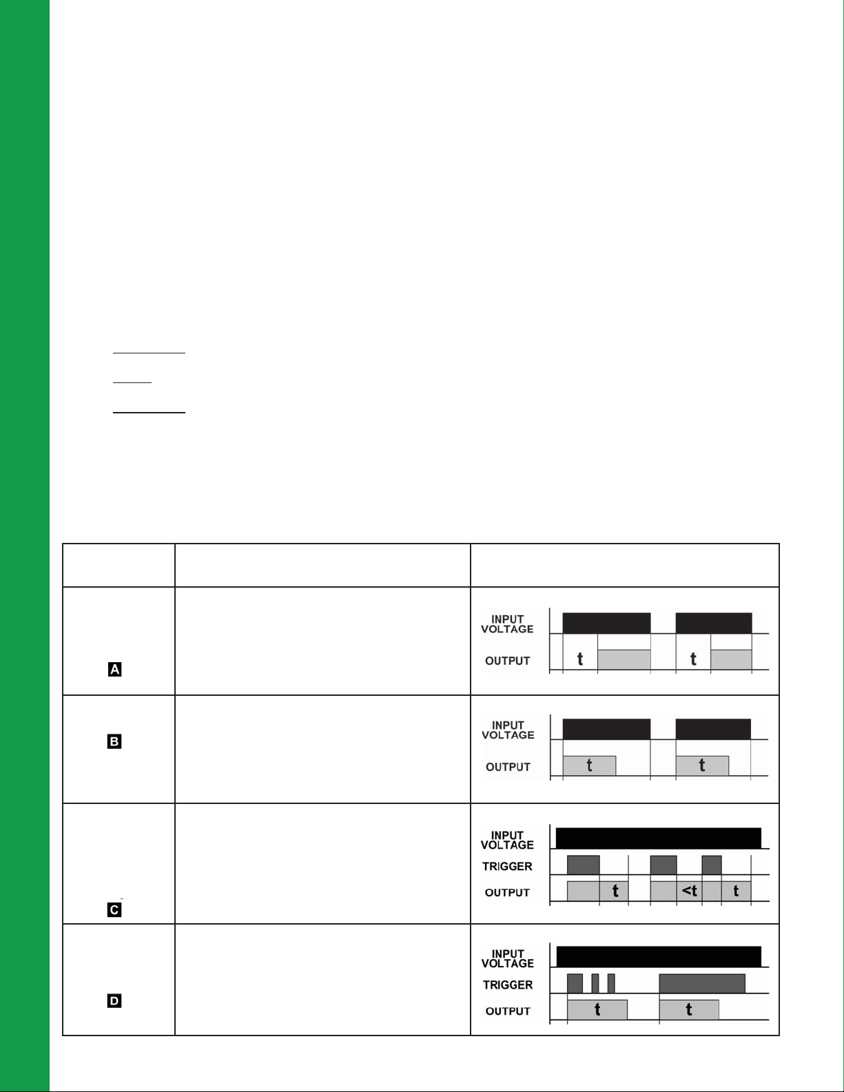
ON DELAY
Delay on
Operate
Delay on Make
INTERVAL ON
Interval
OFF DELAY
Delay on
Release
Delay on Break
Delay on
De-Energization
SINGLE SHOT
One Shot
Momentary
Interval
Upon application of input voltage, the time delay (t)
begins. At the end of the time delay (t), the output is
energized. Input voltage must be removed to reset the
time delay relay & de-energize the output..
Upon application of input voltage, the output is energized and the time delay (t) begins. At the end of the
time delay (t), the output is de-energized. Input voltage
must be removed to reset the time delay relay.
Upon application of input voltage, the time delay relay
is ready to accept a trigger. When the trigger is applied,
the output is energized. Upon removal of the trigger, the
time delay (t) begins. At the end of the time delay (t),
the output is de-energized. Any application of the trigger
during the time delay will reset the time delay (t) and the
output remains energized.
Upon application of input voltage, the time delay relay
is ready to accept a trigger. When the trigger is applied,
the output is energized and the time delay (t) begins.
During the time delay (t), the trigger is ignored. At the
end of the time delay (t), the output is de-energized and
the time delay relay is ready to accept another trigger.
44
DEFINITION OF TIMING FUNCTIONS
Function/Code Operation Timing Chart
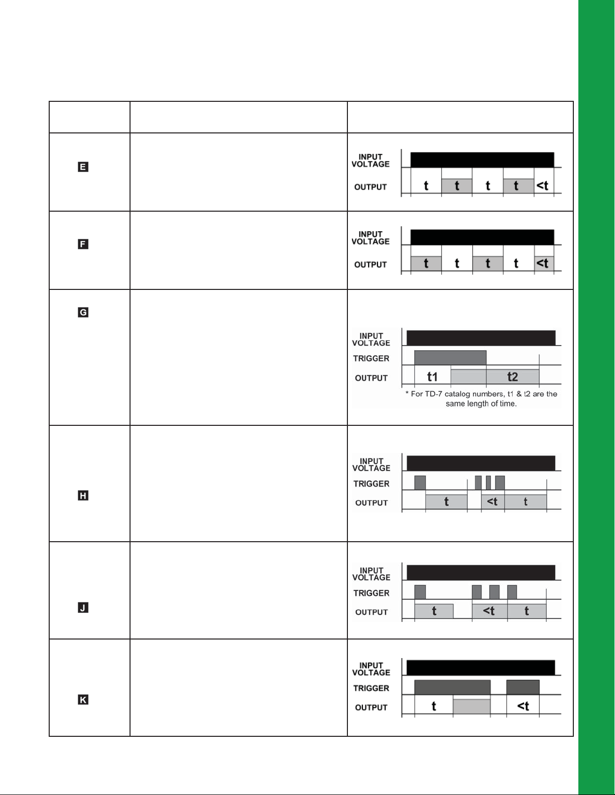
FLASHER
(Off First)
FLASHER
(ON First)
ON/OFF DELAY
Upon application of input voltage, the time delay (t)
begins. At the end of the time delay (t), the output is
energized and remains in that condition for the time
delay (t). At the end of the time delay (t), the output
is de-energized and the sequence repeats until input
voltage is removed.
Upon application of input voltage, the output is energized
and the time delay (t) begins. At the end of the time
delay (t), the output is de-energized and remains in that
condition for the time delay (t). At the end of the time delay (t), the output is energized and the sequence repeats
until input voltage is removed.
Upon application of input voltage, the time delay relay
is ready to accept a trigger. When the trigger is applied,
the time delay (t1) begins. At the end of the time delay
(t1), the output is energized. When the trigger is removed, the output contacts remain energized for the time
delay (t2). At the end of the time delay (t2), the output is
de-energized & the time delay relay is ready to accept
another trigger. If the trigger is removed during time
delay period (t1), the output will remain de-energized and
time delay (t1) will reset. If the trigger is reapplied during
time delay period (t2), the output will remain energized
and the time delay (t2) will reset.
time delay relays | definition of timing functions
SINGLE SHOT
FALLING EDGE
WATCHDOG
Retriggerable
Single Shot
TRIGGERED
ON DELAY
Upon application of input voltage, the time delay relay
is ready to accept a trigger. When the trigger is applied,
the output remains de-energized. Upon removal of the
trigger, the output is energized and the time delay (t)
begins. At the end of the time delay (t), the output is
de-energized unless the trigger is removed and re-applied prior to time out (before time delay (t) elapses).
Continuous cycling of the trigger at a rate faster than the
time delay (t) will cause the output to remain energized
indef nitely.
Upon application of input voltage, the time delay relay
is ready to accept a trigger. When the trigger is applied,
the output is energized and the time delay (t) begins. At
the end of the time delay (t), the output is de-energized
unless the trigger is removed and re-applied prior to time
out (before time delay (t) elapses). Continuous cycling
of the trigger at a rate faster than the time delay (t) will
cause the output to remain energized indef nitely.
Upon application of input voltage, the time delay relay
is ready to accept a trigger. When the trigger is applied,
the time delay (t) begins. At the end of the time delay (t),
the output is energized and remains in that condition as
long as either the trigger is applied or the input voltage
remains. If the trigger is removed during the time delay
(t), the output remains de-energized & the time delay (t)
is reset.
45
 Loading...