

Macromatic TCF-F SERIES Installation Instructions
INSTALLATION INSTRUCTIONS
TCF-F SERIES
OVER TEMPERATURE & SEAL LEAKAGE RELAYS
December 2017, Rev A
901-0000-327
DANGER!
Potentially hazardous voltages are present. Electrical shock can cause death or serious injury.
Installation should be done by qualifi ed personnel following all National, State & Local Codes.
BE SURE TO REMOVE ALL POWER SUPPLYING THIS EQUIPMENT BEFORE CONNECTING OR DISCONNECTING WIRING.
READ INSTRUCTIONS BEFORE INSTALLING OR OPERATING THIS DEVICE. KEEP FOR FUTURE REFERENCE.
Installation & Setup
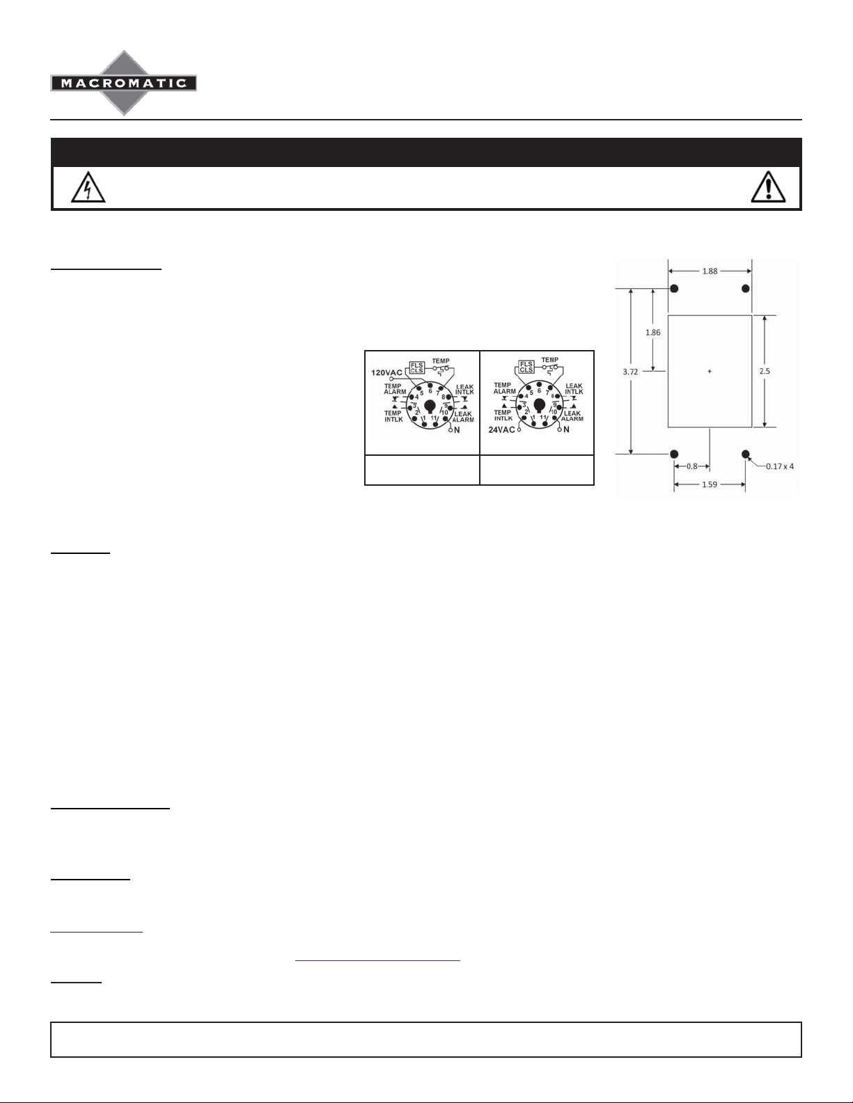
First, use the Cutout Drawing at right to cut the appropriate size hole in the door and drill the
four mounting holes. After mounting the relay, use the appropriate 11 pin back-mounted socket
(Custom Connector OR11-PC socket included with relay).
Wire the socket per the wiring diagram on the side of the
relay or as shown to the right. Make sure to match the
terminal numbers on the socket to the ones shown on
the wiring diagram (the wiring diagram on the relay
is the view looking towards the bottom of the relay
vs. the top of the socket). Use one or two #12-22 solid
or stranded copper or copper-clad aluminum conductors
with terminals of the above sockets--a terminal tightening
torque of 7 in-lbs (OR11-PC) should be used. Plug the
relay into the socket, making sure the key on the center
post is in the proper orientation before insertion. If the
relay must be removed from the socket, do NOT rock
the relay back & forth excessively—the center post
could be damaged.
DIAGRAM 219 DIAGRAM 218
TCF2F
120V AC
TCF8F
24V AC
All Dimensions in
Inches
Operation:
Two wires from the relay are connected to the FLS or CLS leakage sensor which is in series with the pump over temperature switch. A low-voltage
DC signal is applied to measure the current fl ow through the sensor and over temperature switch. The sensor controls the current in this circuit.
These products have isolated output contact relays, one for over temperature and one for seal leakage.
With input voltage applied, normal temperature condition (thermal switch closed) and no seal leakage, the sensor current will be in the normal
range. The over temperature relay is energized and the seal leak relay is de-energized. Both LEDs are Green, indicating normal conditions and
input voltage applied.
When the motor temperature rises and the N.C. thermal switch opens, the sensor current drops to zero. The over temperature relay is de-energized,
opening a contact that had been closed and turning off the pump contactor. The TEMP LED turns Red. If the over temperature condition is cleared,
the unit will reset based on the setting of the Over Temp switch. In the AUTO mode, the unit will reset automatically. In the MANUAL mode, the
Over Temp Reset button must be pushed to clear the alarm and reset the relay.
In a seal leakage condition, contaminating fl uid enters the pump motor cavity. The sensor lowers its resistance, increasing the sensor circuit current
above the trip point. The seal leakage output relay energizes and closes a contact, which can be used to give an alarm indication of a leaking seal.
The SEAL LED turns Red.
Cleared Fault Condition
If either an Over Temp fault condition when the Over T emp switch is set to AUTO or a Seal Leakage fault has been automatically cleared, a cleared
fault indication is displayed by fl ashing the corresponding Red TEMP LED or Red SEAL LED. The fl ashing indication may be manually reset by
pressing the Over Temp Reset button. Note: if either fault still exists when the Over T emp Reset button is depressed, it is ignored.
Shorted Sensor
If the sensor wires are shorted, the unit will display a Shorted Sensor condition by alternately fl ashing the Red SEAL LED and the Red TEMP LED. If
the short is removed, the fault will automatically reset within 30 seconds.
Troubleshooting
If the unit fails to operate properly, check that all connections are correct per the appropriate wiring diagram above. If problems continue,
contact Macromatic at 800-238-7474 or e-mail tech-support@macromatic.com for assistance.
Warranty
All catalog-listed TCF-F Series products manufactured by Macromatic are warranted to be free from defects in workmanship or material under
normal service and use for a period of fi ve (5) years from date of manufacture.
W134 N5345 Campbell Dr. Menomonee Falls, WI 53051 800-238-7474 262-781-3366
sales@macromatic.com www.macromatic.com
 Loading...