

Macromatic PLPU SERIES Installation Instructions
INSTALLATION INSTRUCTIONS
PLPU SERIES
THREE-PHASE MONITOR RELAYS
April, 2014 (New)
901-0000-109
DANGER!
Potentially hazardous voltages are present. Electrical shock can cause death or serious injury.
Installation should be done by qualified personnel following all National, State & Local Codes.
BE SURE TO REMOVE ALL POWER SUPPLY ING THIS EQUIPMENT BEFORE CONNECT ING OR DISCONNECTING WIRING.
READ I NST RU CT IONS BE FOR E I NSTALL ING OR OPER ATING T HIS DEV ICE . K EE P FOR FUT UR E RE FER ENC E.
IMPORTANT: R EAD THIS FIRST IF REPLACING A PLP SERIES PRODUCT WITH DATE CODE OF 1414 OR EARLIER
Macromatic has obsoleted the PLP208 , PLP 240, P LP400 & PLP480 sin gle voltage product s and replaced all of them wit h the PLP U, whic h w orks on any
line-lin e voltage from 190-500V. The PLP U functions th e same and can be used in place of these older produc ts wit hout any special setup . This change is
effective on products m anufactured w ith Date Code of 1415 or later (2nd week of April 2014). For more inform ation, please contac t Macromatic .
Installation, Wiring & Setup
1. Mount the appropr iate 8 pin oc tal socket i n a suitable enclosur e. NOT E: a 600V-rate d socket such as the M acro matic
70169-D or C ustom Co nnecto r OT08 -PC must be used with these pr oducts on applicat ions g reater th an 300V.
When making conne ctions t o th e socket, make sur e to match the t ermina l numb ers on th e socket to the ones
shown on the wiring diagram (the wiring diagram on the relay is the view looking towards the bottom of the
relay vs. the top of the socket). Use one or two #12-22 solid or s tranded copper or c opper-c lad aluminum condu ctors
wit h ter minal s on t he ab ove Macr omati c or C us tom C onnec tor sock ets —a ter min al tig hten ing torq ue of 12 in -lbs sh ould
be used.
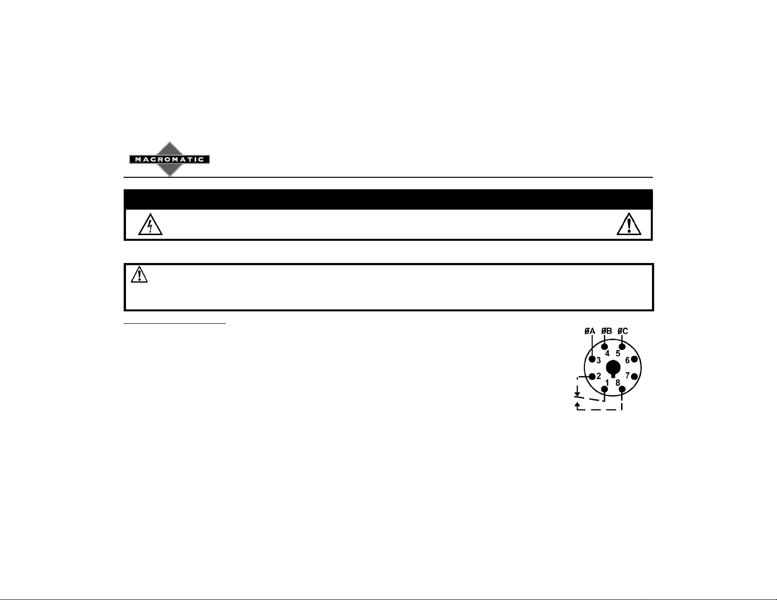
2. Connect the three-ph ase line-line voltage to terminals 3, 4 and 5 (s ee W iring Diagram on the side of t he relay or at
right). A connection to the neutral or g round is not requi red in W ye syst ems. DO N OT c onnect output wir es to
terminals 1, 2 and 8 until later (Step 5).
3. Plug the three-ph ase monitor relay into the socket, making s ure the key on the center p ost is in th e proper orientation
before inser tion. If the r ela y must be r emov ed fro m the socket , do NOT rock th e r elay back and f ort h exce ssiv ely —the center po st
could be dam aged.
(Continued on Back)
Diagram 23
Installation, Wiring & Setup (Continued)
4. A pply t hree- phas e voltage. The L ED in dic ator s houl d illu min ate sol id
(For Load Side connection, contact Macromatic)
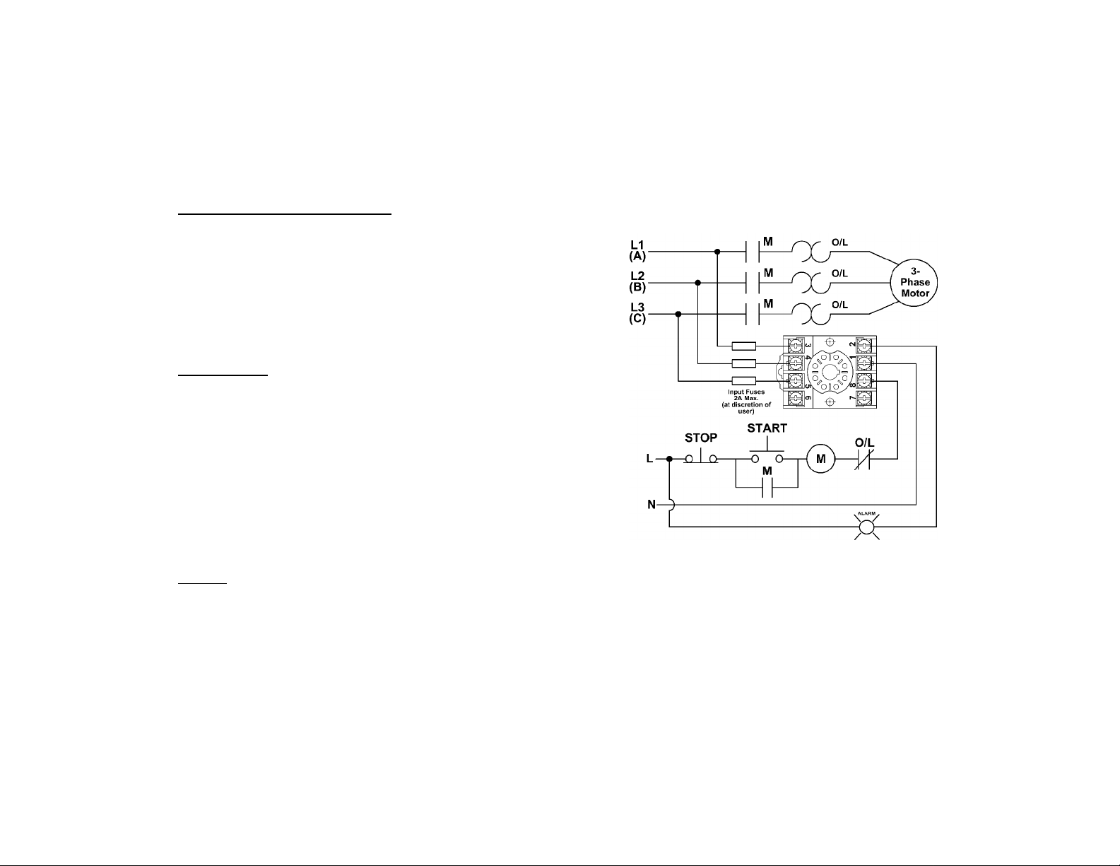
Typical Connections
GR EEN . I f the L ED t ur ns s oli d RE D, a ph ase r evers al (ou t- of- seq uenc e)
condition exists and must be corrected. REMOVE three-phase voltage
and switch any two of t he thr ee line conne ctions to en sure t he phase
sequence (rotatio n) is cor rect. If the LED is f lashing Red, a phase loss
condition exists . Make sure all thr ee phases are present. Check for a
bl own f us e or a l oose o r br oken wir e.
5. Connect the outpu t terminals to termin als 1, 2 & 8. W hen all connec tions
are made, appl y three-phas e line-line volt age.
Troubleshooting
If the L ED is s oli d Red , a ph ase r evers al (ou t-o f-s equ enc e) c ondit ion exist s.
REMOV E three-phase voltage and switch any two of th e three line connections
to en sur e t he pha se seq uenc e (r otat ion ) i s c orr ect . Th e LE D s hou ld b e sol id
Gr een wi th the c orr ect seq uenc e.
If th e LED is f lashing Red, a ph ase loss condit ion exists. Make sur e all three
phases are present. Check f or a blown fus e or a loose or broken wire. T he
LED s hould be solid Green with all three phases pres ent.
If the un it f ail s to op erat e proper ly, ch eck t hat all con nect ions are c orr ect per th e
appropriate wiring diagram on the product.
Warranty
All catalog-li sted PLP Series pr oducts manuf actured by Macromatic are warranted to be free from defects in workmanship or m aterial under normal
service and us e for a period of f ive (5) years f rom date of manufac ture.
 Loading...