

Macromatic PAP SERIES Installation Instructions
INSTALLATION INSTRUCTIONS
PAP SERIES
THREE-PHASE MONITOR RELAYS
April, 2014 (Replaces July, 2004)
901-0000-106
DANGER!
Potentially hazardous voltages are present. Electrical shock can c ause death or serious injury.
Installation should be don e b y qualified perso nne l following all National, State & Local Codes.
BE SURE TO REMOV E ALL POWE R SUPPLYIN G T HIS EQUIPMENT BEFORE CONNEC TING OR DISCONNEC TING WIRING.
READ INSTRUCTIONS BEFOR E INSTALLING OR OPERATING THIS DEVICE. KEEP FOR FUTUR E R EFE RENC E.
IMPORTANT: READ THIS FIRST IF REPLACING A PAP SER IES PRODUCT WITH DATE CODE OF 1414 OR EARLIER
Macromatic made several product design enhancements on all PAP S eries products manufact ured wi th Date Code of 1415 or later (2nd week of April 2014 ).
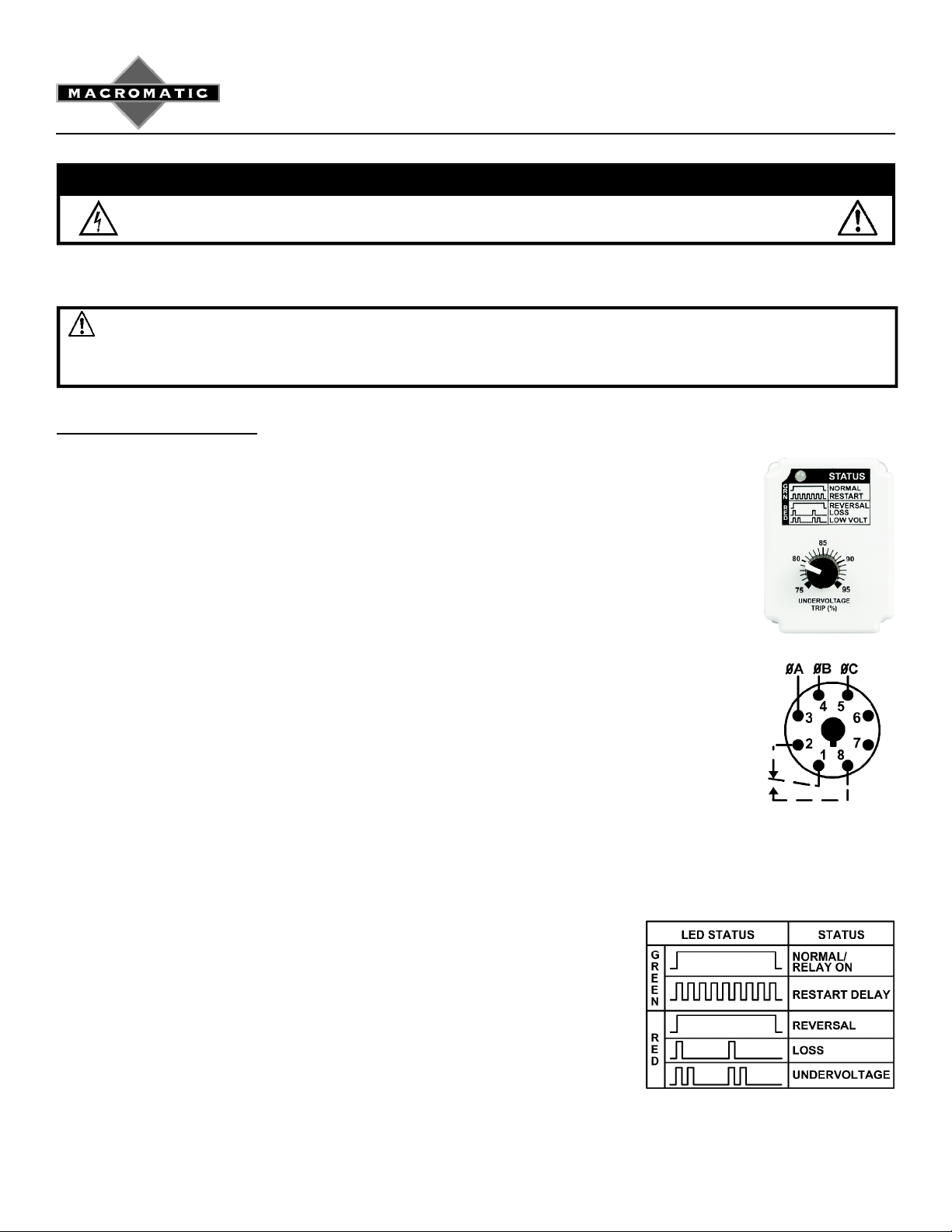
These inclu de eliminati ng the separate 50/60Hz sc ales on the Undervoltage Trip dial setting and replacing it with a single scale that w orks on both 50 &
60 Hz (se e phot o bel ow rig ht) & n ew LE D f ault cod es. Basi c fu nc ti onali ty & p rot ect ion h as been ret aine d. F or m ore i nfor m ati on, p leas e con tac t Mac rom ati c .
Install ation, Wir ing & Setup
1. Mount the appropriate 8 pin octal socket in a suitable enclosure. NOTE: a 600V-rated socket
such as the Macromatic 70169-D or Custom Connector OT08-PC must be used with
these products on applications gre ater than 300 V. When making connections to the
socket, make sure to match the terminal numbers on the socket to the ones shown on
the wiring diagram (the wiring diagram on the r ela y is the view looking towards the
bottom of the relay vs. the top of the socket). Use one or two #12-22 solid or stranded
copper or copper-clad aluminum conductors with terminals on the above Macromatic or Custom Connector sockets—a terminal tightening torque of 12 in-lbs should be used.
2. Initially, set the UNDERVOLTAGE knob to 75% (minimum).
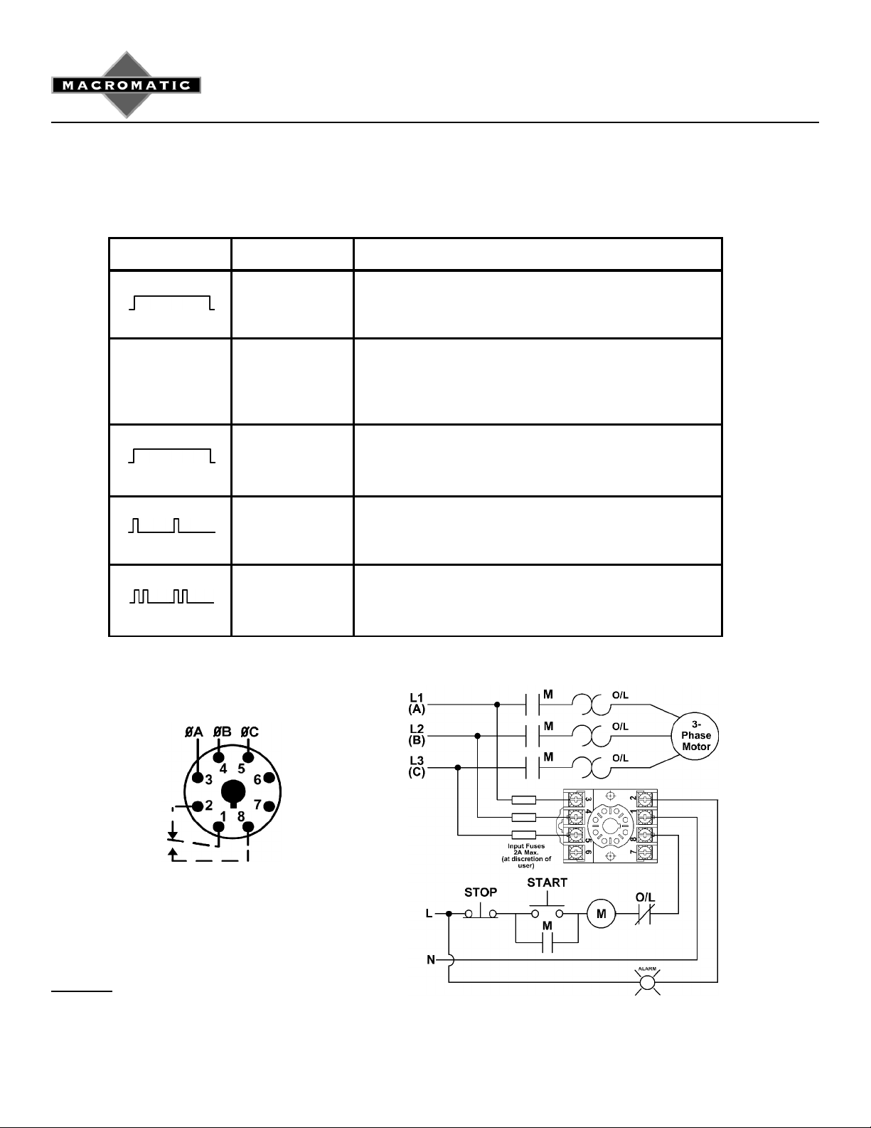
3. Connect the three-phase line-line voltage to terminals 3, 4 and 5 (see Wiring Diagram on the
side of the relay or at right). A connection to the neutral or ground is not required in Wye
systems. DO NOT connect output wires to terminals 1, 2 and 8 until later (Step 7).
4. Plug the three-phase monitor relay into the socket, making sure the key on the center post is in
the proper orientation before insertion. If the relay must be removed from the socket, do
NOT rock the relay back and forth excessively—the center post could be damaged.
5. Apply three-phase voltage. The LED indicator should illuminate solid GREEN. If the LED turns
RED solid or flashing, a fault condition exists and must be corrected. Use the LED St atus T able
at right to determine exact cause of fault. Make required corrections.
6. REMOVE THREE-PHASE VOLTAGE. Set the UNDERVOLTAGE TRIP knob betw een 75 and
95% of the line-line voltage setting. This value should be the same as the minimum operating
voltage for the equipment to be adequately protected.
7. Connect the output terminal wires to terminals 1, 2 and 8 (see Wiring Diagram on the side of the relay or below).
8. When all connections are made, apply three-phase line-line voltage. The
LED indicator should illuminate solid GREEN when all voltage conditions are
correct.
9. If the LED does not illuminate solid GREEN during regular operation, a fault
condition has occurred. REMOVE THREE-PHASE VOL T AGE, and check
for proper phase rotation, presence of all three phases, and low voltage
conditions. Use the LED Status Table at right to determine exact cause
of fault. Correct if necessary. Re-energization is automatic upon correction
of the fault condition.
Diagram 23
(Continued on Back)
INSTALLATION INSTRUCTIONS
THREE-PHASE MONITOR RELAYS
Troub lesho oting Guide
LED STATUS SITUATION SOLUTION
GREEN Motor is not starti ng The relay is in the run mode and working properly. Either another
control device is preventing the motor from starti ng or all wiring
should be checked.
PAP SERIES
NO INDICATION Relay is not
energized and/or
motor is n ot running
RED On power-up or with
motor running
RED Phase loss Make sure all three phases are present. Check for a blown fuse or
RED Low voltage Measure the three line-to-line voltages. If the average of these
Verify L1, L2 and L3 (A, B & C) are connected to terminals 3, 4
and 5. Measure the three line-to-line voltages. If any of the
voltages are below the specified minimum operation voltage, the
relay does not have enough power to operate. Check to see why
operating voltage is low and correct.
The relay is sensing a phase reversal or phase out-of-sequence
(rotation) condition. REMOVE THREE-PHASE VOLTAGE and
switch any two of the three line connections to ensure the phase
sequence (rotation) is correct.
a loose or broken wire.
three voltages is below the UNDERVOLTAGE TRIP knob setting,
the relay has tripped due to a low voltage condition. Check for low
voltage condition and correct i t.
T ypical Connections
(For Load Side connection, contact Macromatic)
Diagram 23
Warranty
All catalog-listed PAP Series products manufactured by Macromatic are warranted to be free from defects in workmanship
or material under normal service and use for a period of five (5) years from date of manufacture.
 Loading...