

Macromatic ISP Series Installation Guide
INSTALLATION INSTRUCTIONS
ISP PLUG-IN INTRINSICALLY SAFE RELAYS
SERIES A
June, 2016 Rev B
901-0000-260
DANGER!
Potentially hazardous voltages are present. Electrical shock can cause death or serious injury.
Installation should be done by qualifi ed personnel following all National, State & Local Codes.
BE SURE TO REMOVE ALL POWER SUPPLYING THIS EQUIPMENT BEFORE CONNECTING OR DISCONNECTING WIRING.
READ INSTRUCTIONS BEFORE INSTALLING OR OPERATING THIS DEVICE. KEEP FOR FUTURE REFERENCE.
Installation & Setup
1. Mount the unit in a suitable enclosure in a non-hazardous area. Only use the 8 pin octal socket that was supplied with the relay.
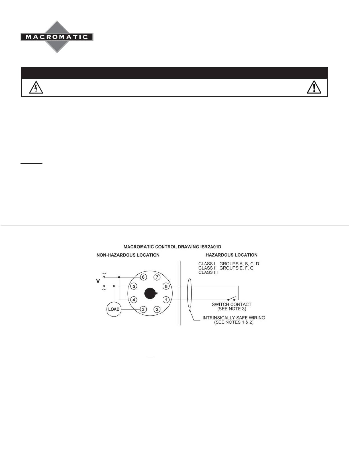
2. Connect wiring per Macromatic's Control Drawing ISR2A01D (on back). Follow all hazardous code requirements while installing
wiring to switch input terminals.
Warranty--All intrinsically safe products offered by Macromatic are warranted to be free from defects in workmanship or material under
normal service and use for a period of One (1) Year from date of manufacture.
UL Control Drawing ISR2A01D
Notes:
1. All intrinsically safe wiring shall be separated from non-intrinsically safe wiring. Refer to Article 504 of the National Electrical Code
(ANSI/NFPA 70) for installation of intrinsically safe wiring.
2. Maximum distance between unit and switch contacts is 1,000 feet.
3. Switch contact shall be any non-energy storing or generating switch type device containing no capacitance or inductance.
4. Device must be installed in Omron socket PF083A and with locking clips attached to base.
5. Cable capacitance plus intrinsically safe equipment capacitance (Ci) must be less than the marked capacitance (Ca). Cable
inductance plus intrinsically safe equipment inductance (Li) must be less than the marked inductance (La) shown on any
associated apparatus used.
6. The simple apparatus (fl oat switch) connected to the ISR shall not be mounted on other electrical apparatus that has a voltage
and current rating higher than the ISR (see Entity Parameters Voc & Isc below). A simple apparatus (such as a fl oat switch) is
defi ned as an electrical component or combination of components of simple construction with well defi ned electrical parameters
that does not generate more than 1.5V, 100mA and 25mW, or a passive component that does not dissipate more than 1.3W and is
compatible with the intrinsic safety of the circuit in which it is used.
7. If the electrical parameters of the cable are unknown, then a capacitance of 60 pF/ft and an inductance of 0.20 uH/ft are to be
used. Cable capacitance and cable inductance are calculated as follows:
60pF/ft x 100 = 6.0nF 0.2 μH/ft x 100 = 20μH
8. Entity Parameters: VOC = 9.33V ISC = 0.218mA CA = 3.6μF LA = 100mH
 Loading...