

Page 1

© 2017 MacroAir Technologies Toll Free: 866 668 3247 Fax: 909 890 2313 ww w.macroair fans.com 1
Rev. Date 032217
Page 2

© 2017 MacroAir Technologies Toll Free: 866 668 3247 Fax: 909 890 2313 ww w.macroair fans.com 1
Rev. Date 032217
Table of Contents
Caution & Safety ................................................................................................................................. 2
Fan Network Ordering ........................................................................................................................ 3
Network Installation
Network Wiring Requirements .................................................................................................. 4
Network Wiring Configurations ................................................................................................. 5
Temp/Humidity Sensor Location (Optional) ............................................................................... 6
Network Excess Cable ................................................................................................................ 7
Wiring Diagrams ......................................................................................................................... 8
Connection Method ..................................................................................................................... 9
Temp/Humidity Sensor Installation (Optional) .......................................................................... 12
Connect Fans To Network ..........................................................................................................13
Configuration and Operation
Screen Setup ............................................................................................................................... 14
Screen Flow ................................................................................................................................ 15
Controller Home Screen ............................................................................................................. 16
Setpoint ....................................................................................................................................... 17
Fan Select Screen ....................................................................................................................... 18
Fan Settings Screen.................................................................................................................... 19
Address Screen ........................................................................................................................... 2 0
Mkey ............................................................................................................................................ 2 1
Fan Diameter Screen .................................................................................................................. 22
Startup Sequence ....................................................................................................................... 23
Controller Dimensions ....................................................................................................................... 24
Warranty Information ......................................................................................................................... 25
Technical Support ............................................................................................................................... 26
Page 3

© 2017 MacroAir Technologies Toll Free: 866 668 3247 Fax: 909 890 2313 ww w.macroair fans.com 2
Rev. Date 032217
Caution & Safety
READ THE ENTIRE MANUAL BEFORE OPERATING THE FAN. Ensure that all safety practices
and instructions are followed during the installation, operation, and servicing of the fan. Failure
to apply these safety practices could result in death or serious injury. If you do not understand
the instructions please call our Technical Department for guidance (Technical Support contact
information can be found on page 26.
All fan controls and incoming power should only be installed by qualified technicians familiar
with the requirements of the NEC and local codes. Refer to appropriate portions of this manual
for other important requirements. Failure to follow these guidelines will void the manufacturer’s
warranty.
Installation is to be in accordance with the national electrical code, ANSI/NFPA 70-1999 and local
codes.
HAZARD OF ELECTRIC SHOCK, EXPLOSION, OR ARC FLASH.
Read and understand this manual before installing or operating a fan unit. Installation,
adjustment, repair, or maintenance must be performed by qualified personnel.
The user is responsible for compliance with all international and national electrical code
requirements with respect to grounding of all equipment.
Many of the parts of this unit operate at line voltage. DO NOT TOUCH.
Install all covers before applying power or starting and stopping the unit.
DAMAGED EQUIPMENT
Do not operate or install any fans or fan accessories that appear to be damaged.
Failure to follow this instruction can result in death, serious injury, or equipment damage.
MAINTENANCE AND SERVICE:
If the fan does not operate properly using the procedures in this manual, BE CERTAIN TO
REMOVE ALL POWER TO THE UNIT and contact our technical department for further assistance.
Keep all body parts clear of moving part at all times.
All electrical troubleshooting and repair must be done by a qualified technician and meet all
applicable codes.
REFER TO FAN INSTALLATION MANUAL(S) FOR FURTHER MAINTENANCE INFORMATION.
Page 4

© 2017 MacroAir Technologies Toll Free: 866 668 3247 Fax: 909 890 2313 ww w.macroair fans.com 3
Rev. Date 032217
Fan Network Ordering
It is important to purchase fans that are setup for a network. MacroAir customizes fans to
operate in a network by:
1) Addressing the fans and
2) Supplying an additional 15ft piece of CAT5
Note: If you did not order your fans for a network by default they will all have Node Address “2”,
and you will be missing necessary materials. Contact technical support to modify your fans for
networking.
Page 5
© 2017 MacroAir Technologies Toll Free: 866 668 3247 Fax: 909 890 2313 ww w.macroair fans.com 4
Rev. Date 032217
Network Wiring Requirements
Network Wiring Requirements:
• Use of Twisted Pair, CAT5e (or higher grade) shielded cable
• Minimum 24 AWG (0.5mm) cross section
• Ground the shielding and drain wire at only one point of the cable run
• Route wires as far away as possible from high voltage AC cables, fluorescent lights, arc
welders, and other equipment that transmits EMI (electromagnetic interference).
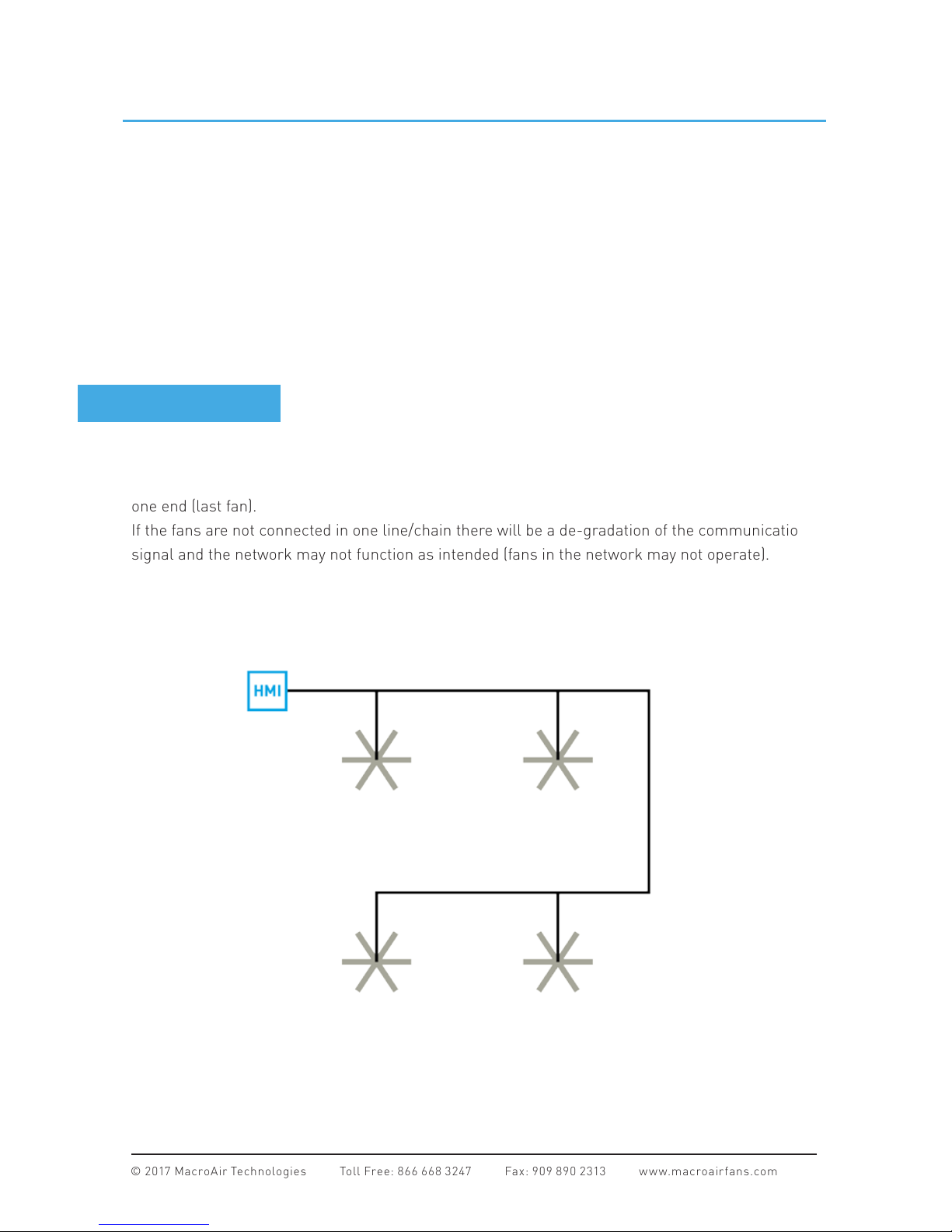
Networked MacroAir fans must be connected in one single line, referred to in this document as
a “daisy chain”. The characteristics of a proper daisy chain are: one beginning (Controller 4) and
one end (last fan).
If the fans are not connected in one line/chain there will be a de-gradation of the communication
signal and the network may not function as intended (fans in the network may not operate).
Daisy Chain
Page 6
© 2017 MacroAir Technologies Toll Free: 866 668 3247 Fax: 909 890 2313 ww w.macroair fans.com 5
Rev. Date 032217
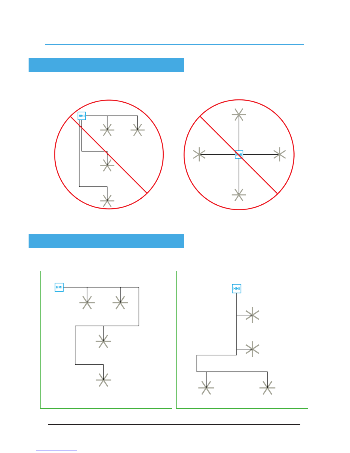
Improper Wiring Configuration
One Beginning, One End
Proper Wiring Configuration
Network Wiring Configurations
Page 7
© 2017 MacroAir Technologies Toll Free: 866 668 3247 Fax: 909 890 2313 ww w.macroair fans.com 6
Rev. Date 032217
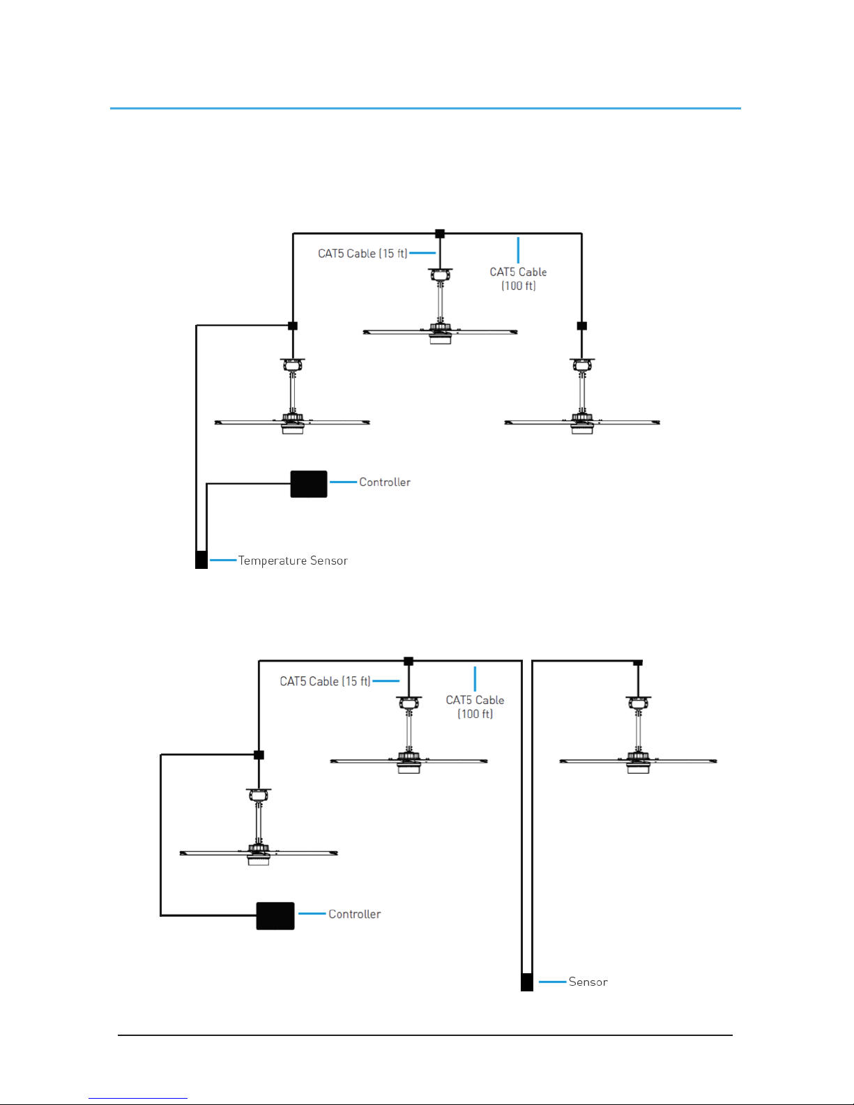
Temp/Humidity Sensor Location
(Optional)
The optional sensor can be placed between two fans or between the controller and a fan as per
the diagrams below. Refer to page 12 for more information.
Page 8
© 2017 MacroAir Technologies Toll Free: 866 668 3247 Fax: 909 890 2313 ww w.macroair fans.com 7
Rev. Date 032217
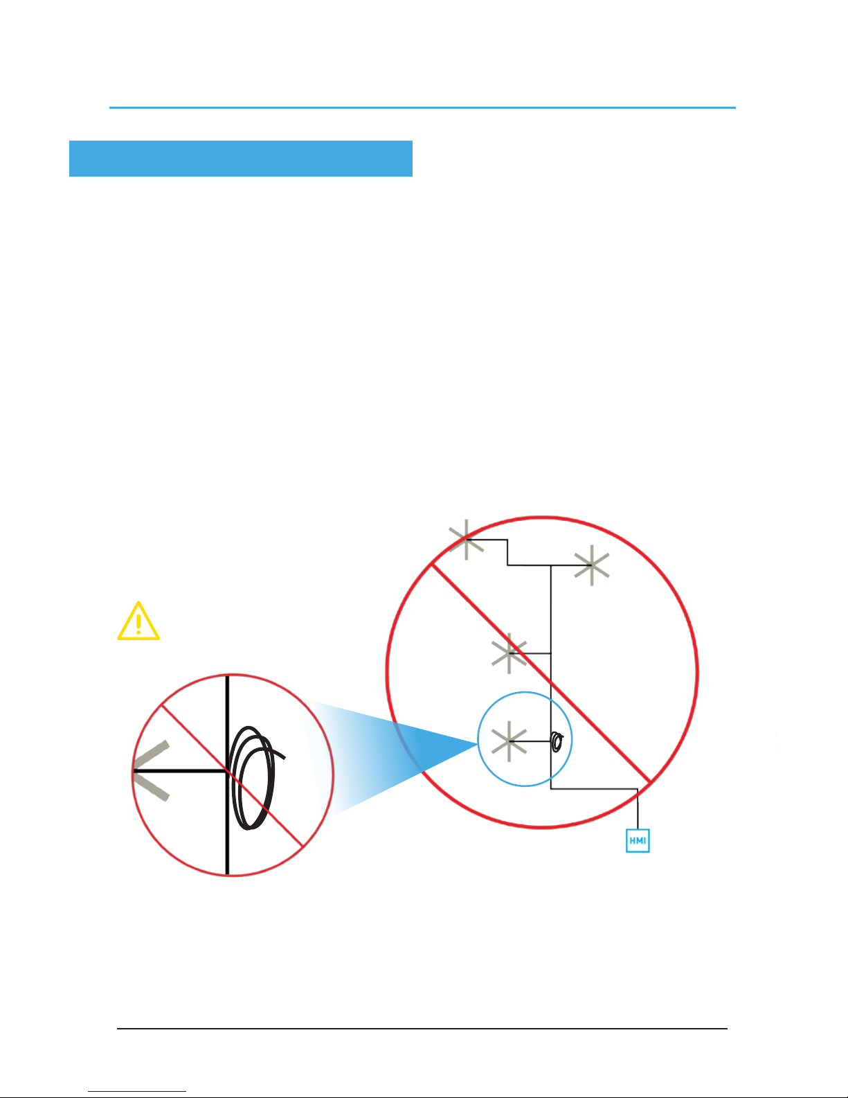
Excess Cable at Connection Point
Trim Excess Cable
Network Excess Cable
With noise being emitted throughout a typical industrial/commercial environment, extra cable
should not be coiled up as the coil itself will create noise/interference in the communication
signal. There should be no more than two feet of excess cable at each connection point.
If more than two feet of cable is needed for future relocation of the fan, run the cable up toward the
ceiling and back down in a horseshoe shape.
ALWAYS AVOID SHARP BENDS OF THE CABLE.
Page 9
© 2017 MacroAir Technologies Toll Free: 866 668 3247 Fax: 909 890 2313 ww w.macroair fans.com 8
Rev. Date 032217
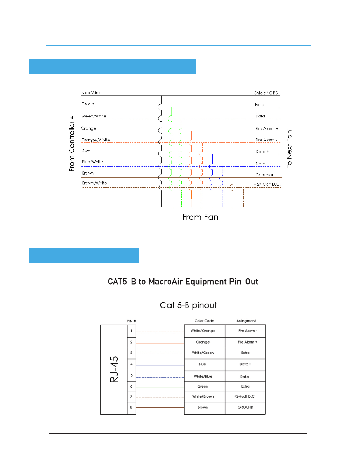
Wiring Diagrams
Typical T-Splice of CAT5
Wiring: CAT5 Pin-Out
Page 10
© 2017 MacroAir Technologies Toll Free: 866 668 3247 Fax: 909 890 2313 ww w.macroair fans.com 9
Rev. Date 032217
Connection Method
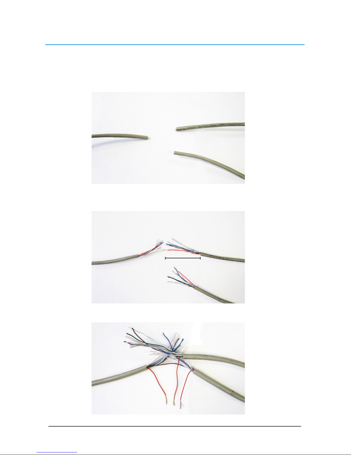
1. Take the incoming CAT5 from the network, the CAT5 from the fan, and the CAT5 going to the
rest of the network. Give some slack (no more than 24”) on each CAT5 to strip the wires and
splice them together. Run the slack up towards the ceiling and back down in a horseshoe shape.
DO NOT roll the excess slack into a circle or coil because this creates a place for the network to
pickup noise on the lines.
2. Strip jacketing off the three CAT5 cables and separate each color wire leaving approximately 2
inches of each wire exposed including the drain/shield wire.
3. Strip approximately 1/2 inch off each color wire leaving the bare copper exposed.
2 inches
Page 11
© 2017 MacroAir Technologies Toll Free: 866 668 3247 Fax: 909 890 2313 ww w.macroair fans.com 10
Rev. Date 032217
Connection Method
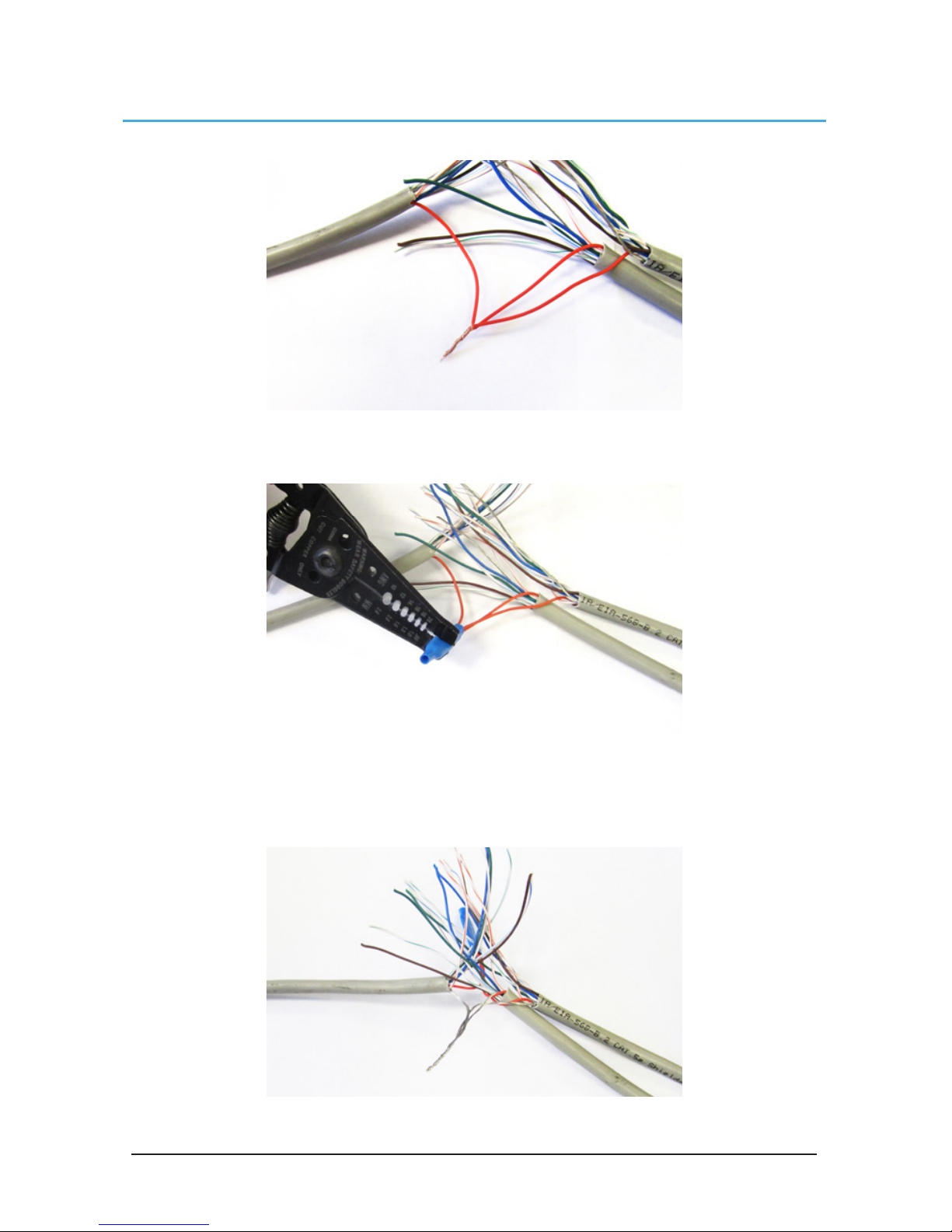
4. Twist the 3 wires of same color from each CAT5 together.
5. Place a gel filled bean crimp onto the end of the 3 wires and use a small crimper or pliers to
crimp the bean tight on the wires.
6. Double check that the 3 drain wire/bare wires are also crimped together as this is what
continues the shielding throughout the network. The shielding and drain wire MUST be connected
to Earth Ground at only one point of the cable run.
Page 12
© 2017 MacroAir Technologies Toll Free: 866 668 3247 Fax: 909 890 2313 ww w.macroair fans.com 11
Rev. Date 032217
Connection Method
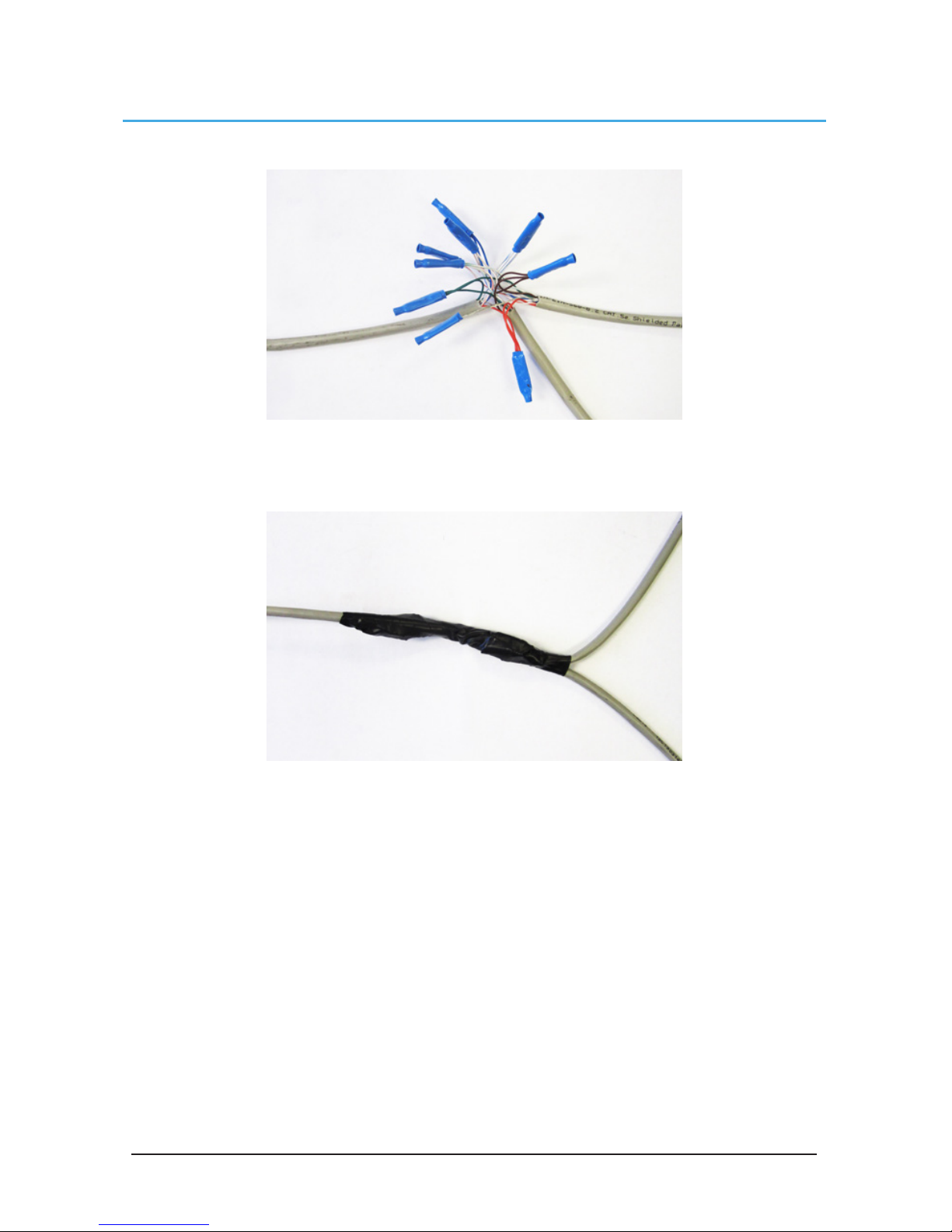
7. Repeat steps 3-5 for all the wires.
8. Once all the wires are crimped, carefully twist the wires up. Then fold them back and tape them
up with electrical tape to clean up your wiring.
9. Make sure to tape or zip tie all 3 CAT5 lines to the structure to support the 3 way splice and
provide strain relief.
Page 13
© 2017 MacroAir Technologies Toll Free: 866 668 3247 Fax: 909 890 2313 ww w.macroair fans.com 12
Rev. Date 032217
Temp/Humidity Sensor Installation
(Optional)
Mounting
1. Mount the floor temperature sensor in the room where the fan/fans are placed within 3ft of
the ground. Use caution when placing the sensor making sure not to place it where there is any
contact with direct sunlight. Refer to the wiring diagrams on page 8 for placement in the CAT5
run.
2. Once the module has been placed it can be wired into the network. Use the brown pair to power
the temperature sensor and the blue pair for communication. If there is enough slack in the cable
you can run the wiring directly in and out at the same point on the sensor module.
3. If there is not enough wire to pull in and out of the sensor splice a length of cable keeping
length to a minimum. Use the bean crimps supplied by Macro Air to wire the lead into the
network. Please refer to network wiring diagram on the following page.
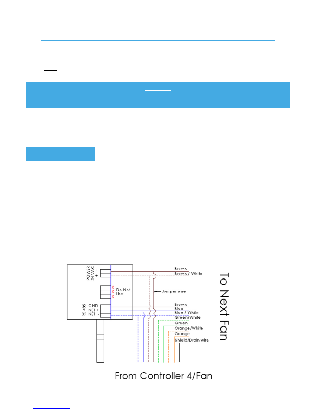
Please refer to the wiring diagram below:
Note: This section of the manual is applicable only if you ordered optional temperature
sensor feature.
Brown - 24VAC- jumpered to GND
Brown/white - 24VAC+
Blue - Net+
Blue/white - Net-
WARNING:
Do not mount the temperature probe on metal as it will then be reading the temperature
of the metal rather than the air temperature.
PINOUT:
Page 14
© 2017 MacroAir Technologies Toll Free: 866 668 3247 Fax: 909 890 2313 ww w.macroair fans.com 13
Rev. Date 032217
Connect Fans To Network
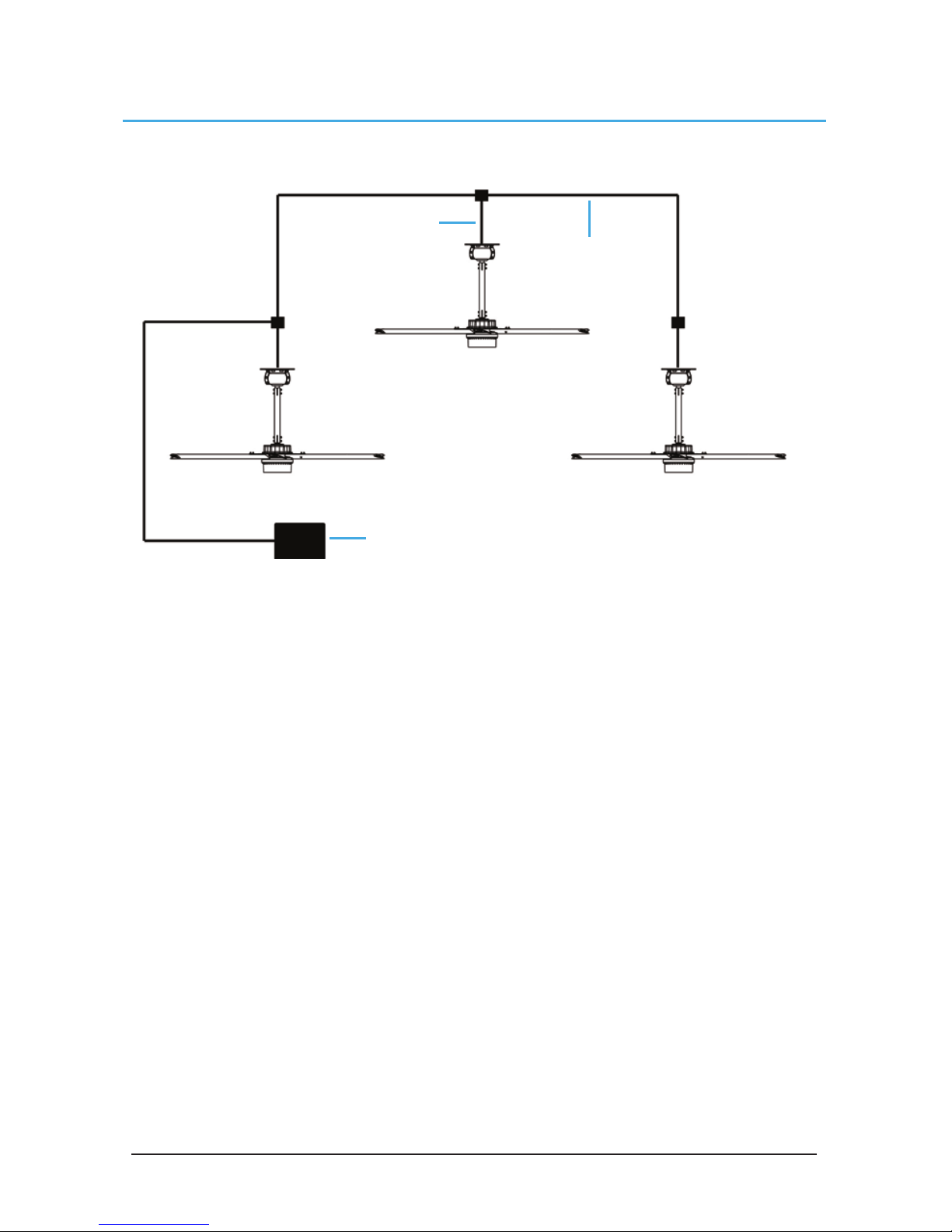
Instructions:
1. Refer to the fan installation manual(s) for fan installation instructions. Fans that are ordered for
networks are labeled with their assigned addresses. Take note of the addresses and ensure that
the fans are installed in the desired locations.
2. Mount the controller in the desired location.
3. Connect all fans as described in the previous pages. Ensure that the 15 ft CAT5 cables are
connected directly to the fans.
4. Review safety and caution information in the fan installation manual(s) and apply power to all of
the fans.
Controller
CAT5 Cable
(100 ft)
CAT5 Cable (15 ft)
Page 15

© 2017 MacroAir Technologies Toll Free: 866 668 3247 Fax: 909 890 2313 ww w.macroair fans.com 14
Rev. Date 032217
The touchscreen may require additional setup before operating the fans. Please refer to the steps
below to properly configure your controller.
1. Power on the fans. The screen will illuminate as soon as power is supplied.
2. The screen will search for fans and take you to the home screen once the scan is complete.
3. AVD 370, AVD3-430, and AirVolution fans do not require further setup. If you only have these
fans on the network, set a speed and direction using the buttons on the home screen. AirVolution
fans will operate normally. AVD 370 and AVD3-430 fans will spin in reverse at a preset speed,
automatically determine the blade length, and resume operation at the speed and direction
commanded.
4. AVD3-450, 550 and 780 fans REQUIRE the blade size to be programmed in order to function
correctly. The blade size is set via the “Settings” (pg 19). Once the size is programmed into every
AVD3-450, 550 and 780 on the network, the fans can be operated normally.
Screen Setup
Page 16
© 2017 MacroAir Technologies Toll Free: 866 668 3247 Fax: 909 890 2313 ww w.macroair fans.com 15
Rev. Date 032217
Screen Flow
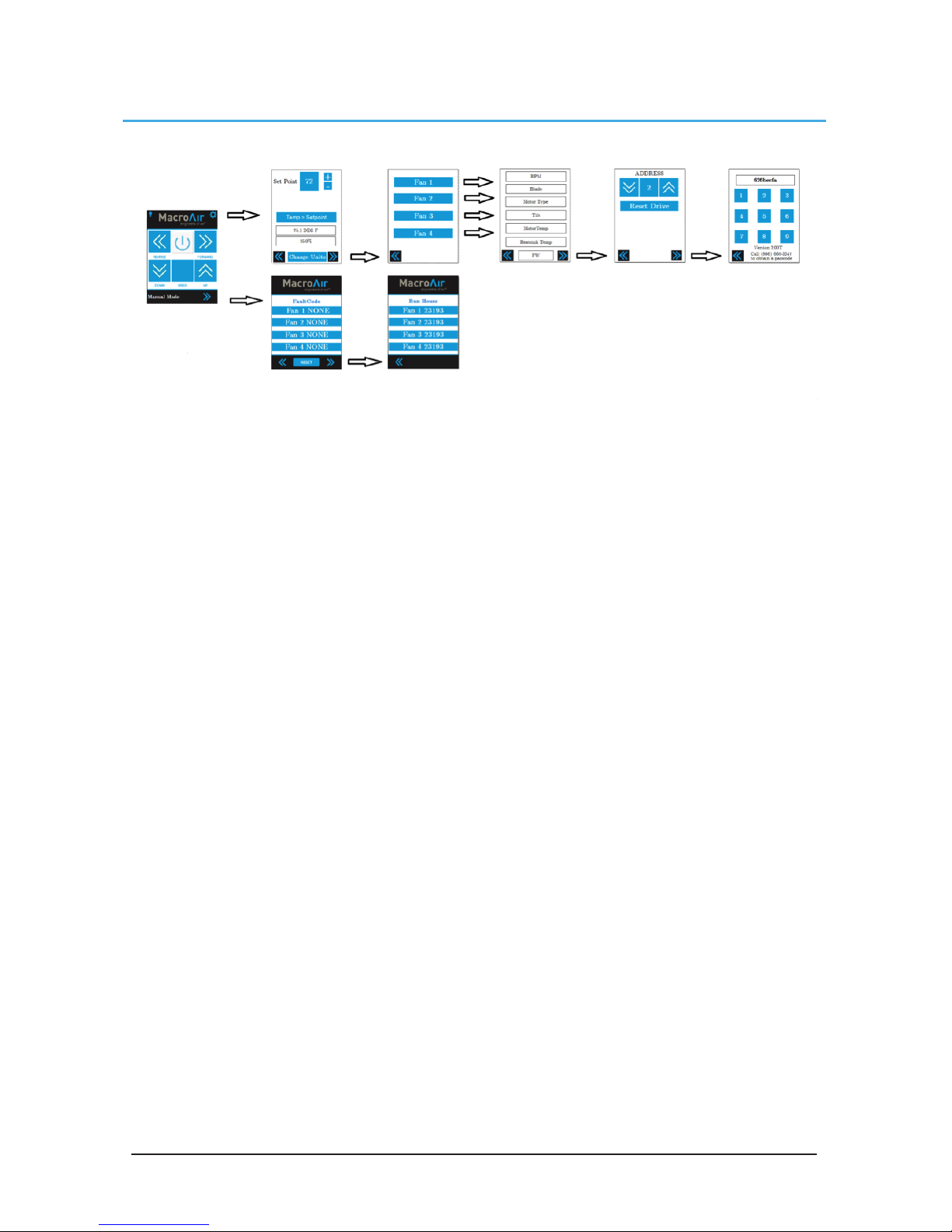
Home Screen - Pg 16
Setpoint - Pg 17
Fan Select - Pg 18
Fan Settings - Pg 19
Fan Address - Pg 20
Mkey - Pg 21
Page 17
© 2017 MacroAir Technologies Toll Free: 866 668 3247 Fax: 909 890 2313 ww w.macroair fans.com 16
Rev. Date 032217
Home Screen
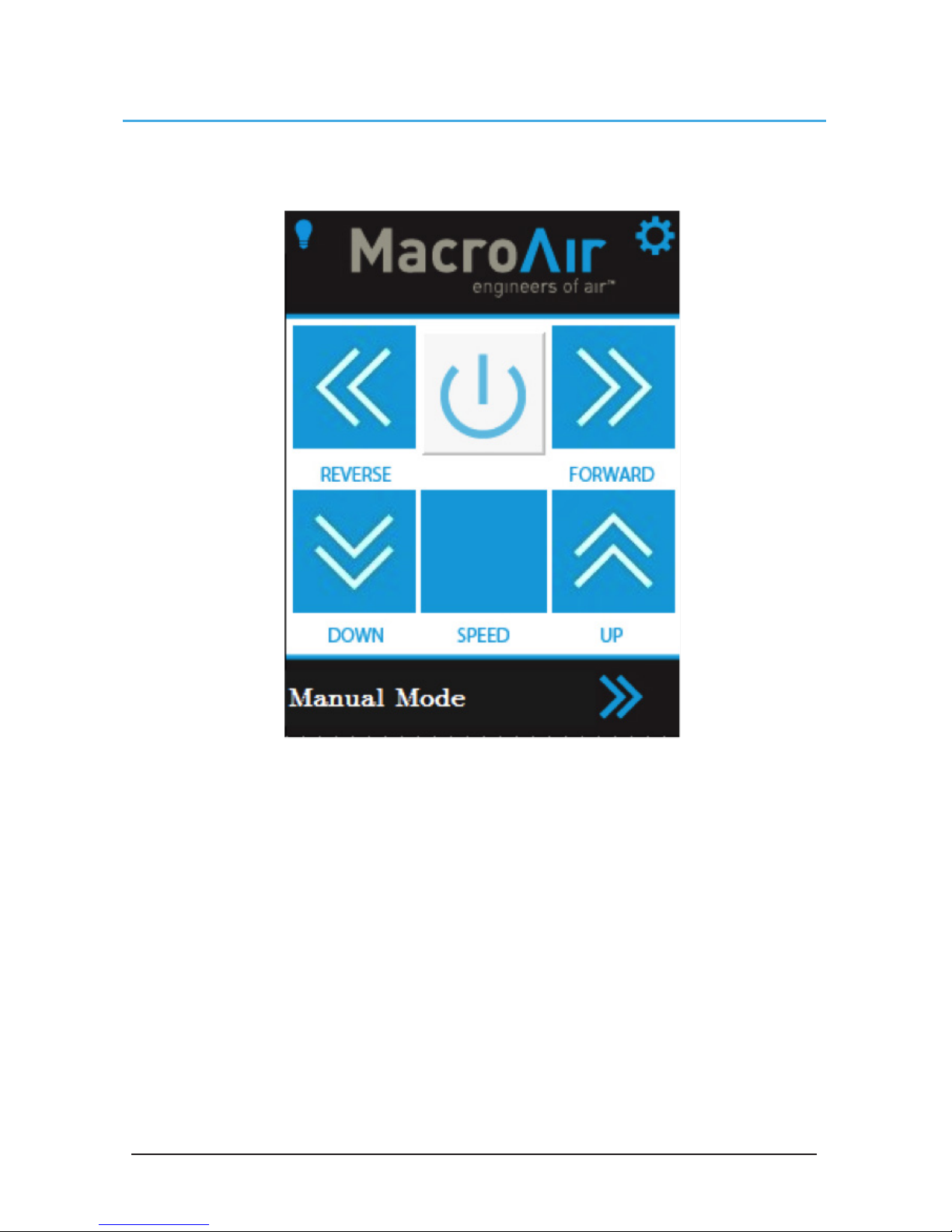
The home screen allows control of all connected fans. Selecting a speed and direction will cause
all fans to run simultaneously. The fans will not run unless speed AND direction commands are
given.
Reverse: Issues a reverse command to all fans
Forward: Issues a forward command to all fans
Power: Turns the fan off if running; turns the fans on if a speed and direction were previously
selected
Down/Up Arrows: Adjust the speed up and down. The speed is displayed as a percentage in the
middle
Light: Turns the light on or off
Settings: Accesses the Fan Select page, from which the settings page can be accessed
Right Arrow: Navigates to the fault code page
Mode: Changes to reflect what mode the controller is in, which is selectable via the setpoint
screen. Manual mode indicates that the fans are controlled manually via the controls.
Temperature mode indicates that the fan will turn on and off according to the temperature set
point. Humidity mode indicates that the fan will turn on and off according to the humidity set point
Page 18
© 2017 MacroAir Technologies Toll Free: 866 668 3247 Fax: 909 890 2313 ww w.macroair fans.com 17
Rev. Date 032217
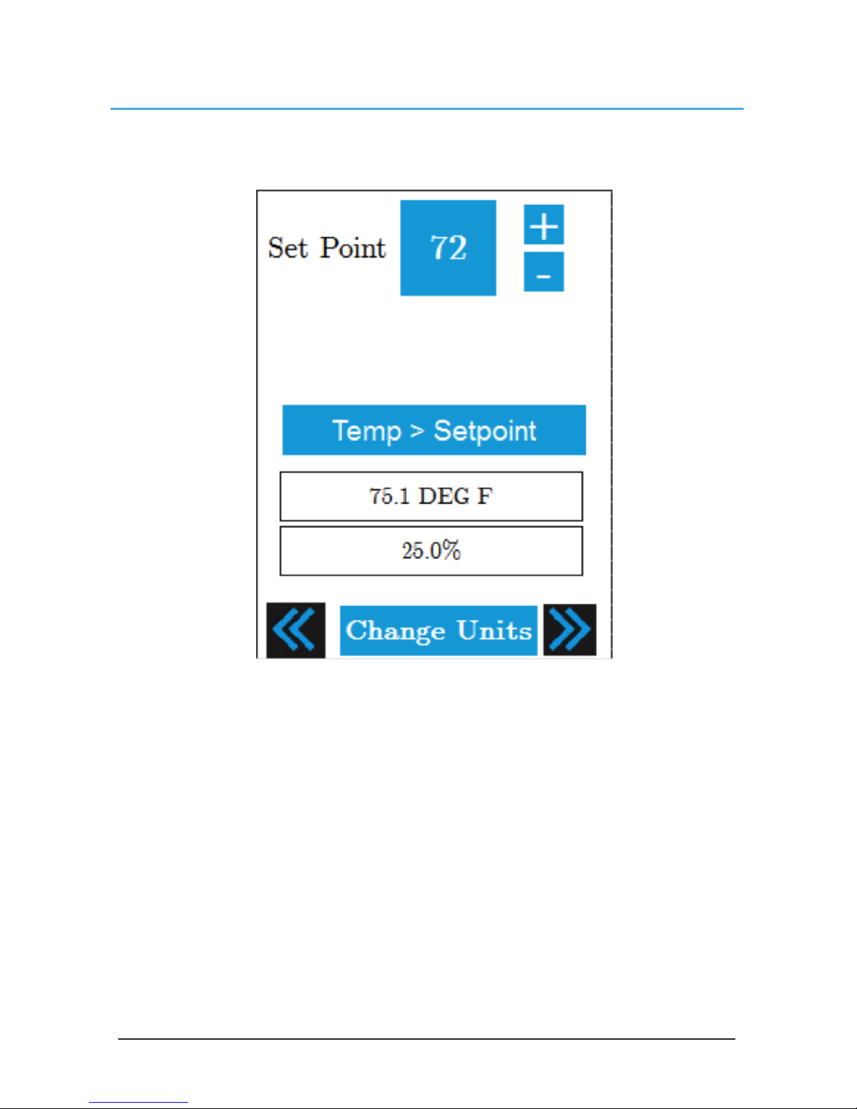
Setpoint
The Setpoint page allows you to select the method of control for your fans, as well as the desired
temperature or humidity setpoint if the optional sensor is installed.
Mode Selection: Allows you to choose between manual mode, temperature mode, and humidity
mode. Manual mode allows you to control the fan from the home screen. Temperature mode
runs the fan according to the speed and direction set on the home screen once the measured
temperature is greater than the set point temperature. Humidity mode runs the fan according to
the speed and direction set on the home screen once the measured humidity is greater than the
set point.
Set Point: Displays the temperature or humidity threshold
Temperature Reading: Displays the ambient temperature. Will read “BAD TEMP READING” if
there is no sensor connected
Humidity Reading: Displays the ambient humidity. Will read “BAD HUMID READING” if there is no
sensor connected
Change Units: Changes the Temperature Reading and Set Point between Fahrenheit and Celsius
Left Arrow: Navigates to the Home Screen
Right Arrow: Navigates to the Fan Select screen
Page 19
© 2017 MacroAir Technologies Toll Free: 866 668 3247 Fax: 909 890 2313 ww w.macroair fans.com 18
Rev. Date 032217
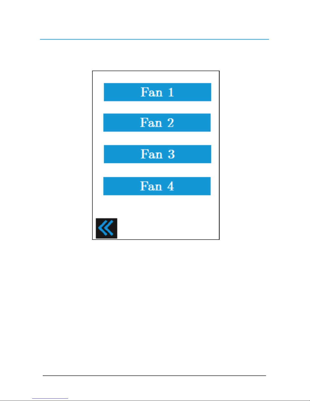
Fan Select
The Fan Select page displays a button for every fan connected to the controller*. Pressing the
button for the desired fan will take you to that fan’s Settings page. Pressing the left arrow will take
you back to the Setpoint page.
* If fans are connected, but not displayed on the Fan Select screen, check your CAT5 connections.
Call technical support if you require further assistance.
Page 20
© 2017 MacroAir Technologies Toll Free: 866 668 3247 Fax: 909 890 2313 ww w.macroair fans.com 19
Rev. Date 032217
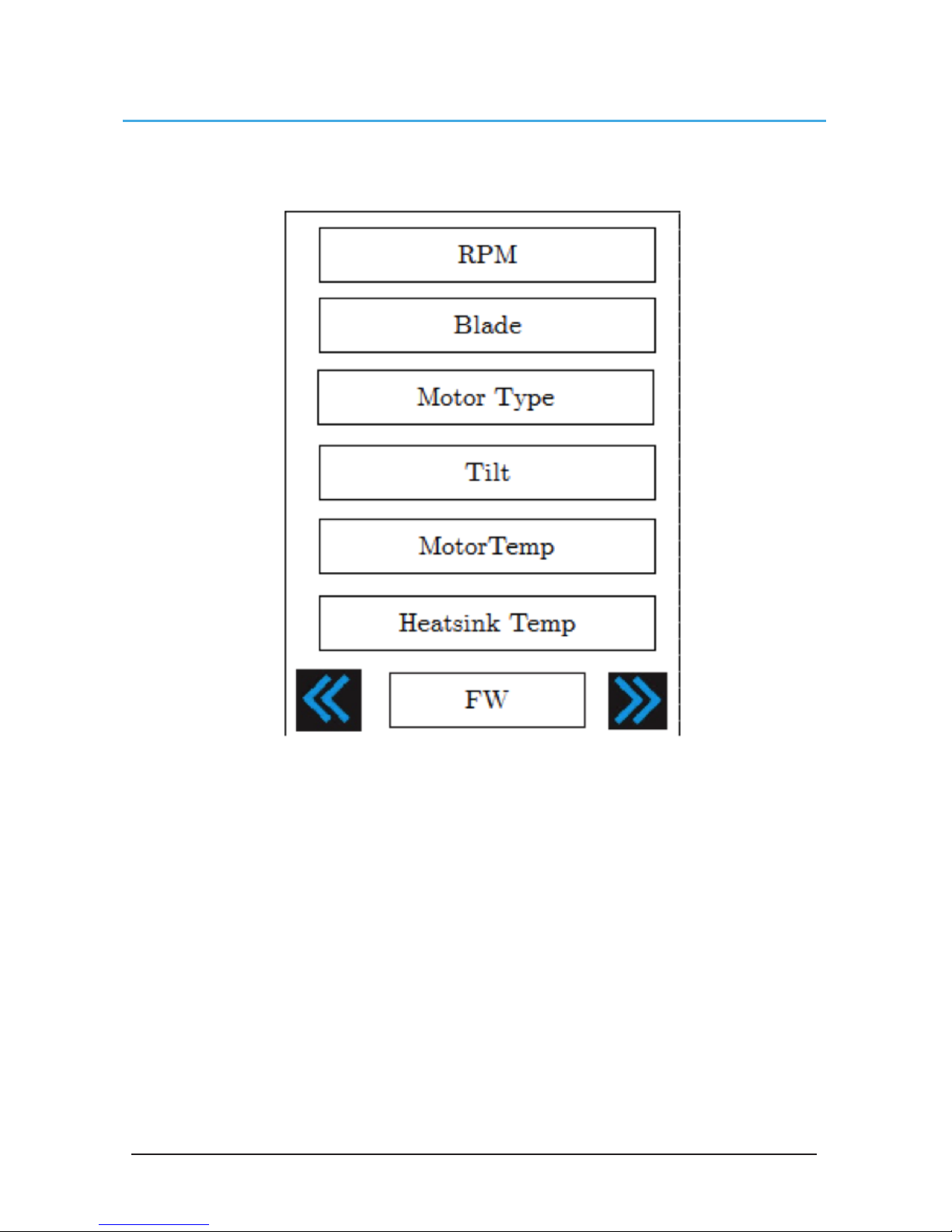
Fan Settings
Selecting a fan will take you to the fan’s settings page. Here you can view various data points on
the fan.
RPM: Displays the current speed of the fan
Blade: Displays the blade size. Pressing here will allow you to program the blade size for AVD
550s, 780s, and AVD3-450s.
Motor Type: Displays the fan model
Tilt: Displays the tilt of the fan. This feature is only available on AVD 550, 780, and AVD3-450 fans
and will always read 0 for 370 and AVD3-430 fans
Motor Temp: Displays the temperature of the motor
Heatsink Temp: Displays the temperature of the heatsink
FW: Displays the firmware version number of the AirBrain
Left Arrow: Takes you to Fan Select
Right Arrow: Takes you to address page
Page 21
© 2017 MacroAir Technologies Toll Free: 866 668 3247 Fax: 909 890 2313 ww w.macroair fans.com 20
Rev. Date 032217
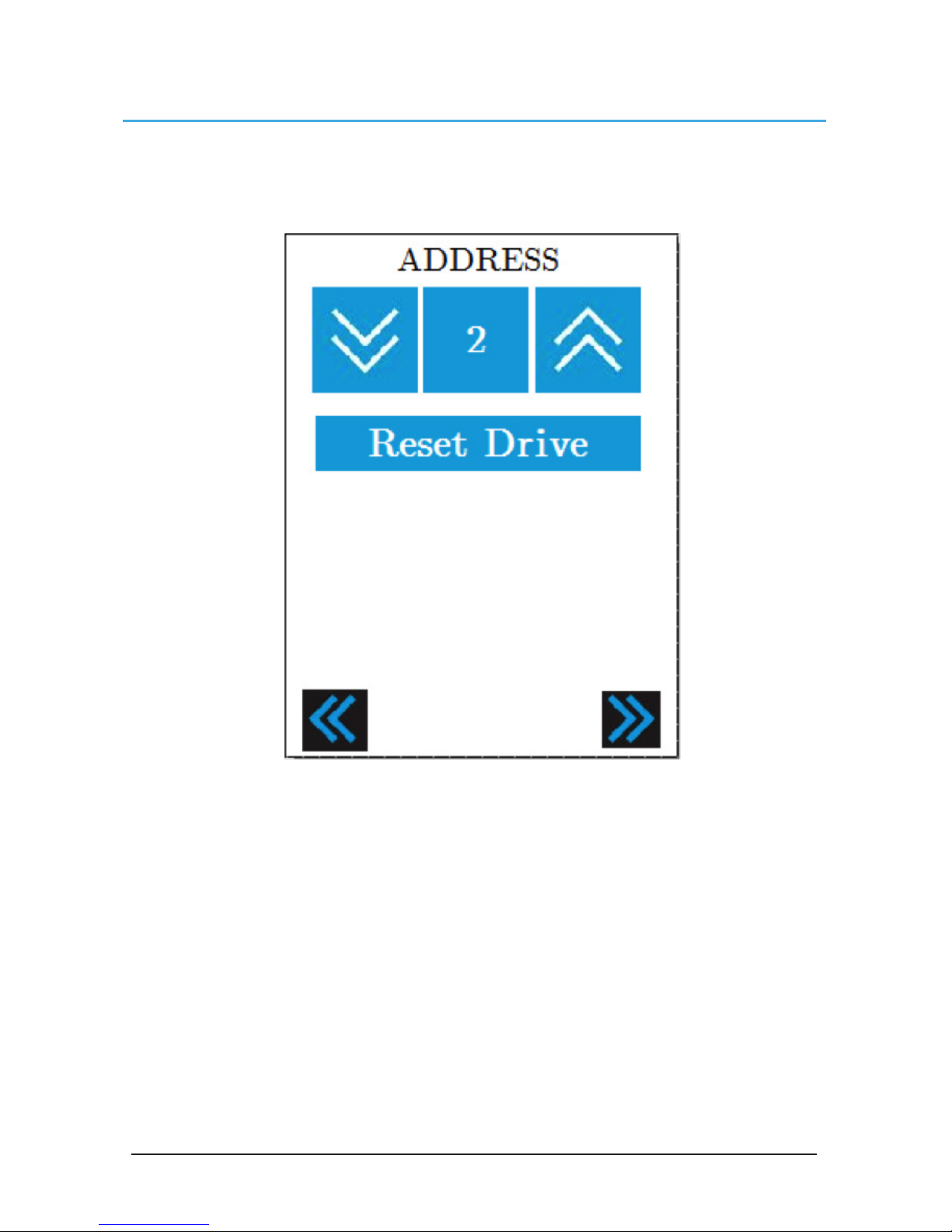
Address
The address page allows you to change the Modbus address of the fan. This is useful for
programming fans for the controller that were not originally shipped with the controller. Please
note that each fan must have a unique address, so be careful when making any changes to ensure
that there are no address conflicts. Only one fan can be connected when changing address.
Up/Down Arrows: Adjusts the address number shown on the screen. Ensure that this number is
unique for every connected fan
Reset Drive: Resets the AirBrain. Address changes do not take effect until the drive is reset
Left arrow: Takes you to Fan Settings
Right Arrow: Takes you to Mkey
Page 22
© 2017 MacroAir Technologies Toll Free: 866 668 3247 Fax: 909 890 2313 ww w.macroair fans.com 21
Rev. Date 032217
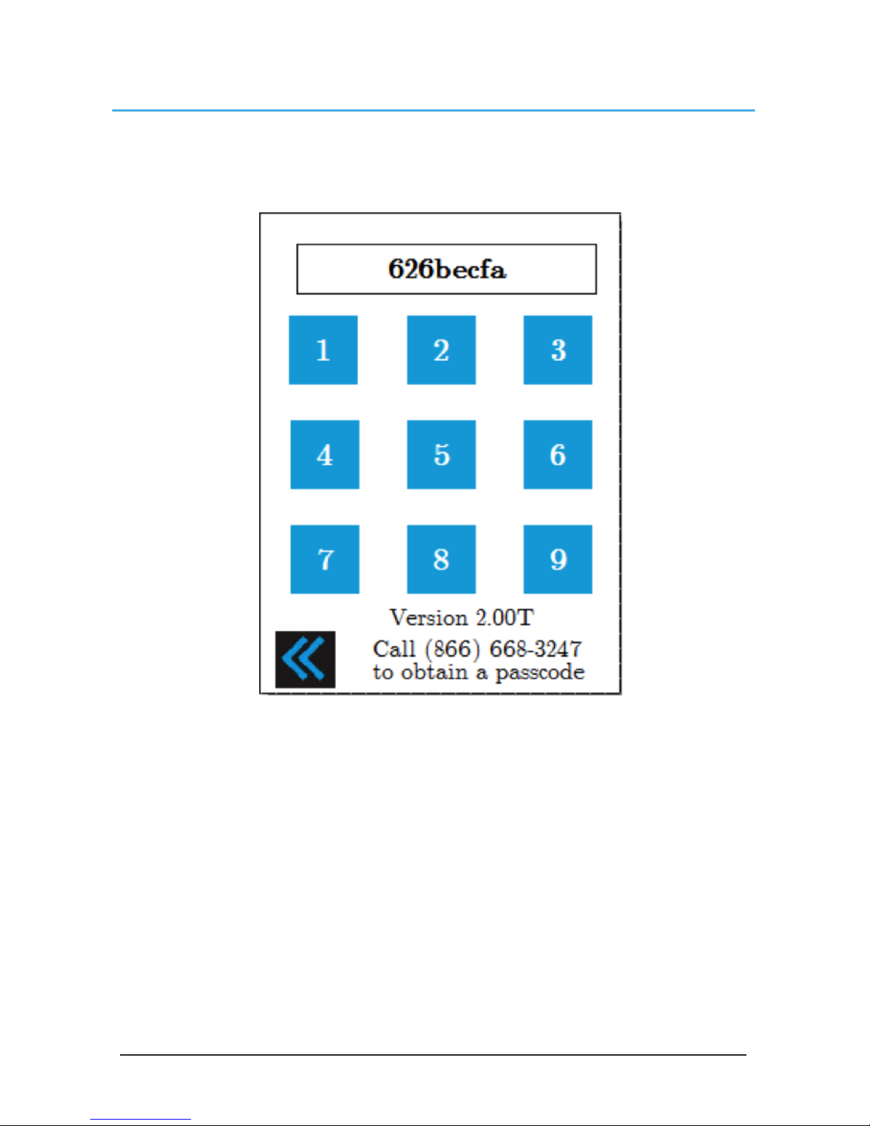
Mkey
The Mkey page prevents unauthorized users from accessing advanced settings on the fan that
could potentially cause damage if misused. For access to advanced settings, please call Technical
Support at 866-668-3247.
Mkey: Displays a code that needs to be relayed to Technical Support for a password. This code is
constantly changing, so you must be in front of the screen when on the phone with MacroAir
Number pad: Technical support will issue you with a 4 digit number once you provide the Mkey.
The 4-digit code can be typed in using the number pad. Please note that the buttons will beep, but
nothing will show on the screen. After the 4 digits are typed in the keypad will automatically take
you to the Calibrate screen
Left Arrow: Takes you to the Address page
Page 23
© 2017 MacroAir Technologies Toll Free: 866 668 3247 Fax: 909 890 2313 ww w.macroair fans.com 22
Rev. Date 032217
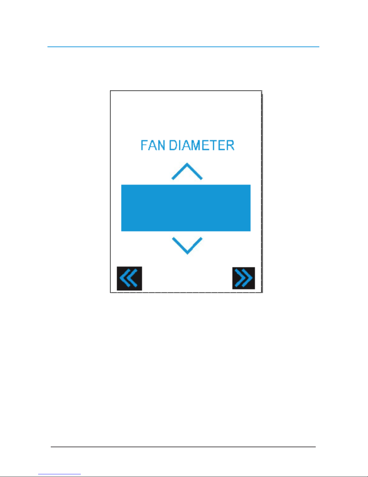
Fan Diameter
The Fan diameter page allows you to set the diameter on 550, 780, and AVD3-450 fans. These
fans will not run properly if the diameter is not set correctly. This screen is reached by pressing
the “Blade” section of the Fan Settings Screen.
Up/Down Arrow: Adjust the diameter up and down. For AVD3-450 fans, adjust the diameter past
24 to access 3-blade fan settings
Left Arrow: Takes you to the Home Screen
Right Arrow: Takes you to the Startup Sequence page
Page 24
© 2017 MacroAir Technologies Toll Free: 866 668 3247 Fax: 909 890 2313 ww w.macroair fans.com 23
Rev. Date 032217
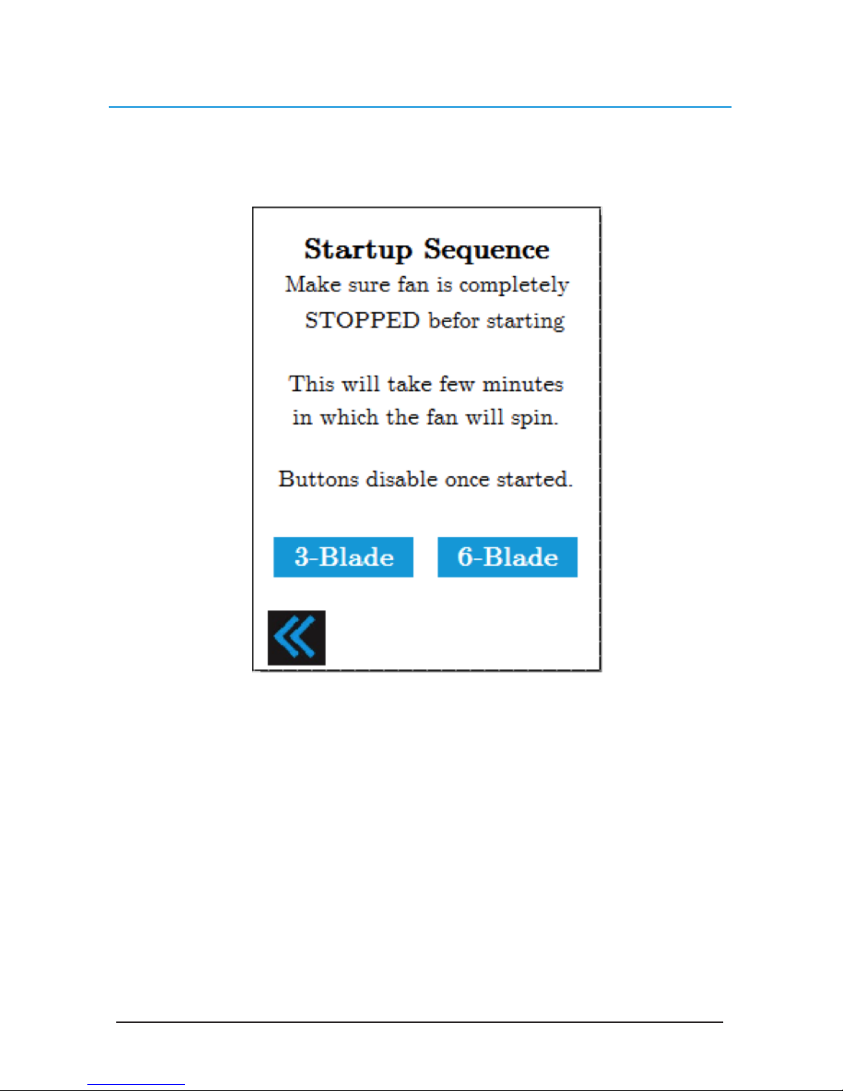
Startup Sequence
The startup sequence page allows you to automatically detect the blade size on AVD 550, 780,
and AVD3-450 fans without manually inputting the diameter on the Fan Diameter page. Press
“3-Blade” for AVD3-450 fans and “6-blade” for 550/780 fans.
Page 25
© 2017 MacroAir Technologies Toll Free: 866 668 3247 Fax: 909 890 2313 ww w.macroair fans.com 24
Rev. Date 032217
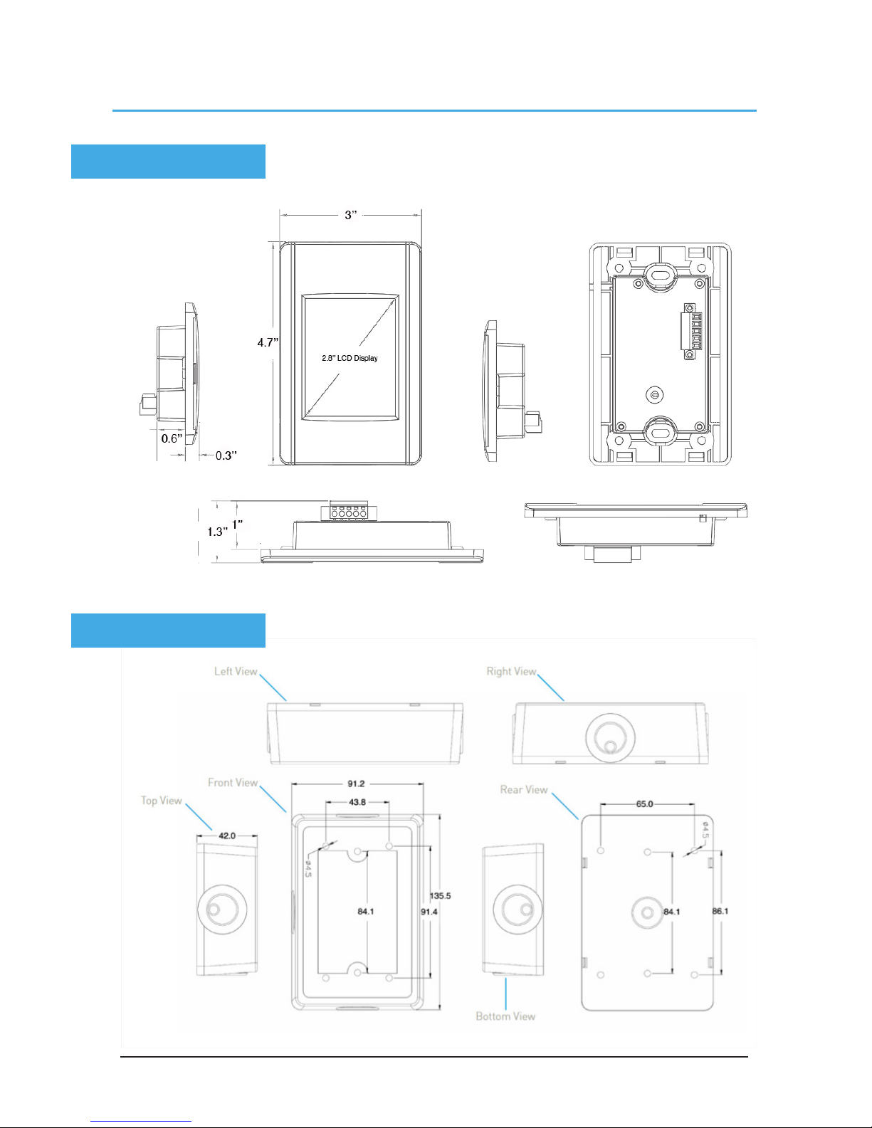
Controller Dimensions
LCD Screen
Enclosure
Page 26

© 2017 MacroAir Technologies Toll Free: 866 668 3247 Fax: 909 890 2313 ww w.macroair fans.com 25
Rev. Date 032217
Warranty Info
MacroAir 3-Year Controller Limited Warranty
MacroAir Technologies, Inc.
Warrantor: The warrantor for the limited warranties set forth herein is MacroAir Technologies Inc.
(“MacroAir”).
Limited Warranty: This limited warranty (this “Warranty”) applies only to the original End-User (the
“End-User”) of any MacroAir Technologies’ Three or Six Blade fan Controllers, Network Controllers or
AIRLYNK Building Management System interfaces hereafter referred to as the “Product” and cannot
be transferred. This Warranty applies even in the event that the Product is initially sold by MacroAir for
resale to an End-User.
What This 3 Year Warranty Covers: MacroAir warrants that the Product will have a “service life”
(defined below) of Three Years from the date of purchase (the “Three-Year Service Life”) when used in
accordance with the operation and maintenance procedures prescribed in the MacroAir Installation and
Owners Manuals and Controller Instructions. If MacroAir finds, in its sole discretion, that any Product
has not provided the Three-Year Service Life, MacroAir will, as its sole obligation and the End-User’s
sole remedy for MacroAir’s breach of this warranty, repair or replace the Product, at its option, F.O.B.
MacroAir’s factory, for a charge, payable by the End-User to MacroAir on the following basis:
What This Limited Warranty Does Not Cover: This Warranty does not cover any defects or damages
caused by: (a) failure to properly store the Product before installation; (b) shipping and delivery of the
Product if shipping is FOB Factory; (c) neglect, accident, abuse, misuse, misapplication, or incorrect
installation; (d) repair or alteration not authorized in writing by MacroAir personnel or performed by an
authorized MacroAir Customer Service Engineer or Agent; (e) improper testing, operation, maintenance,
adjustment, or modification of any kind not authorized in writing by MacroAir personnel or performed by
an authorized MacroAir Customer Service Engineer or Agent; or (f) use of the Product under other than
normal operating conditions or in a manner inconsistent with the Product’s labels or instructions.
APPLIES TO ALL MACROAIR PRODUCTS:
Any Warranted Items repaired or replaced pursuant to this Warranty will be warranted for the remaining
portion of the original Warranty subject to all the terms thereof. MacroAir shall not be responsible for
any charges for testing, checking, removal or installation of Warranted Items not authorized in writing
by MacroAir personnel or performed by an authorized MacroAir Customer Service Engineer or Agent.
Limitation Of Liability: The remedies of the End-User set forth herein are exclusive and are the sole
remedies for any failure of MacroAir to comply with its obligations hereunder. In no event shall MacroAir
be liable in contract, in tort (including negligence or strict liability) or otherwise for damage to property
or equipment other than the Products, including loss of profits or revenue, loss of use of Products, cost
of capital, claims of customers of the End-User or any special, indirect, incidental or consequential
damages whatsoever. The total cumulative liability of MacroAir hereunder whether the claims are based
in contract (including indemnity), in tort (including negligence or strict liability) or otherwise, shall not
exceed the price of the Product on which such liability is based. MacroAir shall not be responsible for
failure to provide service or parts due to causes beyond MacroAir’s reasonable control.
End-User’s Obligations: In order to receive the benefits of this Warranty, the End-User must use the
Product in a normal way; follow the Product’s Installation and Owners Manuals; and protect against
further damage to the Product if there is a covered defect.
Other Limitations: MacroAir’s obligations under this Warranty are expressly conditioned upon receipt
by MacroAir of all payments due to it (including interest charges, if any). During such time as MacroAir
has not received payment of any amount due to it for the Product, in accordance with the contract terms
under which the Product is sold, MacroAir shall have no obligation under this Warranty. Also during
such time, the period of this Warranty shall continue to run and the expiration of this Warranty shall not
be extended upon payment of any overdue or unpaid amounts.
Costs Not Related To Warranty: The End-User shall be invoiced for, and shall pay for, all services not
expressly provided for by the terms of this Warranty, including without limitation, site calls involving
an inspection that determines no corrective maintenance is required. Any costs for replacement
equipment, installation, materials, freight charges, travel expenses or labor of MacroAir representatives
outside the terms of this Warranty will be borne by the End-User.
Obtaining Warranty Service: Call MacroAir Technologies Inc., Customer Service Department at
909.890.2270. MacroAir will not accept any product for return, credit or exchange unless expressly
authorized by MacroAir in writing and delivered FOB MacroAir factory with proper Return Authorization
Number attached to the product.
Page 27

© 2017 MacroAir Technologies Toll Free: 866 668 3247 Fax: 909 890 2313 ww w.macroair fans.com 26
Rev. Date 032217
Technical Support
For installation assistance, application
questions, technical support & any other
inquiries, please contact our Technical
Support team at (866) 668-3247.
Page 28
© 2017 MacroAir Technologies Toll Free: 866 668 3247 Fax: 909 890 2313 ww w.macroair fans.com 27
Rev. Date 032217
 Loading...