

MacroAir Technologies AirVolution-D 550, AirVolution-D 780, AirVolution D3-430 Installation Manual
Page 1
© 2018 MacroAir Technologies Toll Free: 866 668 3247 Fax: 909 890 2 313 www.macroairfans.com i
Rev. Date 040218
Page 2

© 2018 MacroAir Technologies Toll Free: 866 668 3247 Fax: 909 890 2 313 www.macroairfans.com 1
Rev. Date 040218
Table of Contents
Caution & Safety ................................................................................................................................. 2
Fusing Chart ....................................................................................................................................... 5
Fan Placement & Clearance .............................................................................................................. 6
Fan Clearance - Universal Mount ..................................................................................................... 7
Fan Clearance - Rapid Mount Industrial ........................................................................................... 9
Fan Dimensions .................................................................................................................................. 10
Components (Universal Mount) ......................................................................................................... 11
Components (Rapid Mount) ............................................................................................................... 12
Fan Components & Tools .................................................................................................................. 13
Mounts ................................................................................................................................................ 14
1 - Universal Mount
1.1 Universal Mount - Mounting Bolt Kits ................................................................................. 15
1.1.1 Universal Mount I-Beam (Steel Truss Mounting) ......................................................... 16
1.1.2 Universal Mount Glulam ................................................................................................ 18
1.1.3 Universal Mount Unistrut .............................................................................................. 20
1.2 Universal Mount Extension Tube ......................................................................................... 22
1.3 Universal Mount Motor Unit ................................................................................................. 24
1.4 Safety Cable Installation
1.4.1 Universal Mount I-Beam Safety Cable .......................................................................... 27
1.4.2 Universal Mount Glulam Safety Cable .......................................................................... 28
1.4.3 Universal Mount Unistrut Safety Cable ......................................................................... 29
2 - Rapid Mount Industrial
2.1 Rapid Mount Industrial - Mounting Bolt Kits ....................................................................... 30
2.1.1 Rapid Mount Industrial I-Beam (Steel Truss Mounting) .............................................. 31
2.1.2 Rapid Mount Industrial Glulam ..................................................................................... 33
2.1.3 Rapid Mount Industrial Unistrut .................................................................................... 35
2.2 Rapid Mount Industrial Extension Tube ............................................................................... 37
2.3 Rapid Mount Industrial Motor Unit ...................................................................................... 39
2.4 Safety Cable Installation
2.4.1 Rapid Mount Industrial I-Beam Safety Cable ............................................................... 42
2.4.2 Rapid Mount Industrial Glulam Safety Cable ............................................................... 43
2.4.3 Rapid Mount Industrial Unistrut Safety Cable .............................................................. 44
3 - Guy Wire Installation
3. Guy Wire Installation .............................................................................................................. 45
4 - Drive Installation
4.1 Drive Installation ................................................................................................................... 49
4.1.1 Drive Installation (Low Voltage) ..................................................................................... 50
4.1.2 Drive Installation (High Voltage) .................................................................................... 51
4.2 Control Wiring ....................................................................................................................... 52
5 - Airfoil and Retainer Link Installation
5. Airfoil and Retainer Link Installation ..................................................................................... 53
6 - Disconnect Switch (Recommended)
6.1 Fuse Disconnect Switch Installation .................................................................................... 57
6.2 Emergency Disconnect Schematic ...................................................................................... 58
6.3 Enable (ON)/Disable (OFF) Schematic ................................................................................. 58
7 - Touchpad Remote Setup
7.1 Touchpad Remote Mounting ................................................................................................ 59
7.2 Touchpad Remote Navigation .............................................................................................. 62
7.2 Touchpad Remote Operation................................................................................................ 63
Maintenance Information ................................................................................................................... 64
Mounting Plate Dimentions ............................................................................................................... 65
Mounting Bracket Dimentions ........................................................................................................... 66
Touchpad Dimentions ........................................................................................................................ 67
Troubleshooting ................................................................................................................................. 68
Warranty and Technical Support ....................................................................................................... 74
Page 3

© 2018 MacroAir Technologies Toll Free: 866 668 3247 Fax: 909 890 2 313 www.macroairfans.com 2
Rev. Date 040218
Caution & Safety
This appliance can be used by children aged from 8 years
and above and persons with reduced physical, sensory or
mental capabilities or lack of experience and knowledge if
they have been given supervision or instruction concerning
use of the appliance in a safe way and understand the
hazards involved.
Children shall not play with the appliance.
Cleaning and user maintenance shall not be made by
children without supervision.
READ AND SAVE THE ENTIRE MANUAL BEFORE OPERATING THE FAN. Ensure that all safety
practices and instructions are followed during the installation, operation and servicing of the
fan. Failure to apply these safety practices could result in death or serious injury. If you do not
understand the instructions please call MacroAir for guidance (contact information can be found
on page 74).
The fan installation should follow the recommendations outlined in this manual. MacroAir is not
responsible for any injury or damage to people or property as a result of the user and/or installer
not complying with the recommendations outlined in this manual.
All fan controls and incoming power should only be installed by qualied technicians familiar
with the requirements of the Natural Electric Code (NEC) and local codes. Refer to appropriate
portions of this manual for other important requirements. Failure to follow these guidelines will
void the manufacturer’s warranty.
NOTICE: All electrical controls are congured at the factory and are ready to use. No user
adjustments are available. Follow the included wiring schematics and installation instructions
when installing this device to ensure proper operation. Do not make any changes to any part of
the fan without rst consulting MacroAir.
Installation is to be in accordance with the national electrical code, ANSI/NFPA 70-1999 and local
codes.
This appliance is not intended for use by persons (including children) with reduced physical,
sensory or mental capabilities, or lack of experience and knowledge, unless they have been
given supervision or instruction concerning use of the appliance by a person responsible for their
safety.
Children should be supervised to ensure that they do not play with the appliance.
HAZARD OF ELECTRIC SHOCK, EXPLOSION, OR ARC FLASH.
Read and understand this manual before installing or operating a fan unit. Installation,
adjustment, repair, or maintenance must be performed by qualied personnel.
The user is responsible for compliance with all international and National Electrical Code
requirements with respect to the grounding of all equipment.
Many of the parts of this unit operate at live voltage. DO NOT TOUCH.
Install all covers before applying power or starting and stopping the unit.
Page 4

© 2018 MacroAir Technologies Toll Free: 866 668 3247 Fax: 909 890 2 313 www.macroairfans.com 3
Rev. Date 040218
Caution & Safety
WARNING - TO REDUCE THE RISK OF ELECTRIC SHOCK OR INJURY TO PERSONS, OBSERVE
THE FOLLOWING:
a) Use this unit only in the manner intended by the manufacturer. If you have questions, contact
the manufacturer.
b) Before servicing or cleaning the unit, switch power off at the service panel and lock the service
disconnecting means to prevent power from being switched on accidentally. When the service
disconnecting means cannot be locked, securely fasten a prominent warning device, such as a
tag, to the service panel.
WARNING: If unusual oscillating movement is observed, immediately stop using the ceiling fan
and contact the manufacturer, its service agent or suitably qualied persons.
WARNING: Make sure to power the fan off and lock it out using the IEC/CE approved disconnect
when doing any cleaning and or maintenance to the equipment.
PRIOR TO THE INSTALLATION, ENSURE:
• That the mounting of the suspension system shall be performed by the manufacturer, its
service agent or suitably qualied persons;
• That the fan is to be installed so that the blades are more than 10ft [3.05m] above the oor;
• The model or type reference of a luminaire that may be installed in a fan constructed for
this purpose.
DAMAGED EQUIPMENT
Do not operate or install any fans or fan accessories that appear to be damaged. Failure to follow
this instruction can result in death, serious injury, or equipment damage.
SERVICE:
If the fan does not operate properly using the procedures in this manual, BE CERTAIN TO
REMOVE ALL POWER TO THE UNIT and contact our technical department for further assistance.
Keep clear of moving parts at all times. All electrical troubleshooting and repair must be done by
a qualied technician and meet all applicable codes.
Ensure that the replacement of parts of the safety suspension system device shall be performed
by the manufacturer, its service agent or suitably qualied persons.
Key Safety System Components
MacroAir fans are engineered with key safety features to prevent pieces of the fan from falling in
the unlikely event of a catastrophic failure. Used together, these features provide comprehensive
protection of people, equipment and property. Follow the detailed instructions precisely when
installing fans, including the following:
• Install the safety cable on EVERY fan. The safety cable, if installed per MacroAir
specications, will prevent the fan from falling in the unlikely event that the mounting
system should fail. A MacroAir fan should never be run without a properly installed safety
cable, which is supplied with every fan along with all required hardware. You must install a
safety cable for the warranty to be in effect.
• Install guy wires on every fan, unless otherwise specied. Properly installing the guy wires
is required for proper stabilization during normal operation for some fan and mounting
types (Universal Mounts). In addition, guy wires keep the fan stable in case of earthquakes
or in “outdoor” installations where high wind conditions may occur.
Page 5

© 2018 MacroAir Technologies Toll Free: 866 668 3247 Fax: 909 890 2 313 www.macroairfans.com 4
Rev. Date 040218
Caution & Safety
Mark the Floor to Alert Personnel
When mounting a fan in an area where materials may be elevated into its path, MacroAir
recommends marking or painting the oor with a large crosshatched circle to alert personnel of
the overhead location of fans.
Accelerometer
AVD 550 and 780 fans feature an on-board accelerometer, which will stop the fan and prevent it
from running if it becomes greater than 5 degrees out of level.
Weight Considerations
Ensure the xing means for attachment to the ceiling such as hooks or other devices shall be
xed with a sufcient strength to withstand 4 times the weight of the ceiling fan. The maximum
hanging weight for the Model 550 is 172 lbs [78 kg] and the maximum hanging weight for the
Model 780 is 213 lbs [97 kg]. If there is any uncertainty in the strength of the building structure,
a professional structural engineer should perform a thorough evaluation of the building prior
to purchasing the fans. MacroAir provides guidelines for mounting fans; however, it is the sole
responsibility of the building owner and installer to ensure the safety of the mounting system,
that the building structure is sound and that the installation complies with all federal, state, and
local codes.
Torque
The maximum torque (twisting force) during normal operation that must be handled by the
mounting system, including the building structure. For a Model 550, the maximum potential
torque is 100 ft-lbs [136 N-m]. For a Model 780, the maximum potential torque is 250 ft-lbs [339
N-m].
Check Federal, State, and Local Codes
Check all relevant codes to make sure that all product certications, product listings, and
building regulations are met. Code compliance is the responsibility of the installer.
Windy Conditions
Fans should not be operated when wind is present.
Page 6

© 2018 MacroAir Technologies Toll Free: 866 668 3247 Fax: 909 890 2 313 www.macroairfans.com 5
Rev. Date 040218
Fusing Chart
BRANCH CIRCUIT PROTECTION IS REQUIRED TO PROTECT THE ELECTRICAL COMPONENTS
AND COMPLY WITH UL 507.
Use the table below to select the correct fast acting fuse size for your application. The optional
fuse disconnect switch provided by MacroAir uses class gG fast acting fuses. Fuses must be
purchased separately.
MODEL 550
Max Amp Draw / Fuse Size
Voltage and Phase 8ft 10ft 12ft 14ft 16ft 18ft
110 VAC 1-Phase 9A / 12 13.9A / 20 13.9A / 20 13.9A / 20 15.2A / 20 15.2 A / 20
120 VAC 1-Phase 8.3A / 12 12.7A / 16 12.7A / 16 12.7A / 16 14A / 20 14A / 20
208-240 VAC 1-Phase 4.8A / 6 7.3A / 10 7.3A / 10 7.3A / 10 8.1A / 12 8.1A / 12
208-240 VAC 3-Phase 3.4A / 6 5.3A /8 5.3A / 8 5.3A / 8 6.6A / 10 5.8A / 8
380 VAC 3-Phase 1.9A / 4 2.9A / 4 2.9A / 4 2.9A / 4 3.6A / 6 3.2A / 4
480 VAC 3-Phase 1.5A / 4 2.3A / 4 2.3A / 4 2.3A / 4 2.9A / 4 2.5A / 4
600 VAC 3-Phase 1.2A / 4 1.8A / 4 1.8 A / 4 1.8A / 4 2.3A / 4 2A / 4
MODEL 780
Voltage and Phase 20ft 24ft
208-240 VAC 1-Phase 12.5A / 16 15.1A / 20
208-240 VAC 3-Phase 6.8A / 10 8.2A / 12
380 VAC 3-Phase 3.7A / 6 4.5A / 6
480 VAC 3-Phase 2.9A / 4 3.5A / 6
600 VAC 3-Phase 2.3A / 4 2.8A / 4
Reference page 57 for installation.
Part Numbers:
4A 6A 8A 10A 12A 16A 20A
MERSEN
FUSES
FR10GG50V4 FR10GG50V6 FR10GG50V8 FR10GG50V10 FR10GG50V12 FR10GG50V16 FR10GG50V20
EATON
FUSES
C10G4 C10G6 C10G8 C10G10 C10G12 C10G16 C10G20
DF
FUSES
420004 420006 420008 4200010 4200012 4200016 4200020
Mersen fuses:
http://ep-us.mersen.com/products/catalog/line/ferrule-fuse-links-10x38-gg-400-to-690vac/
Eaton Fuses:
http://www.cooperindustries.com/content/public/en/bussmann/electrical /products/iec_british0/class_gg_gl_
ferrulefuses/class_gg_gl_ferrulefuses10x38mm.resources.html
DF Fuses:
http://www.df-sa.es/products/cylindrical/gg-fuse-links
Page 7

© 2018 MacroAir Technologies Toll Free: 866 668 3247 Fax: 909 890 2 313 www.macroairfans.com 6
Rev. Date 040218
Fan Placement & Clearance
Sprinkler Systems and Fan Placement
In any installation where re sprinklers are in place, fans should not interfere with their correct
operation. Fans should be located no less than 3 feet below a sprinkler, and placed central to
each sprinkler quadrant. Our AirBrain motor controller can be connected to a re suppression
control system which will emergency-stop fans in case of re. Prior to installing fans, review all
codes applicable to sprinkler systems and fans to ensure code compliance (refer to NFPA 13).
Please call MacroAir for guidance (contact information can be found on page 74). However, it is
your sole responsibility to see that the installation is completed to code and that it is correct.
Other Information on Placement and Spacing
If possible, avoid mounting fans directly below lights or skylights to avoid any strobe effect
caused by moving airfoils.
Note, a large fan, 20 – 24 feet in diameter, performs best at 20 to 30 feet above the oor, but
acceptable performance has been demonstrated as low as 10 feet and as high as 50 feet. 24 foot
fans should not be installed in locations that experience high winds.
If the building has a mezzanine, fans should be mounted so a person cannot reach a fan in any
way from the upper level/deck. Make certain that fans are positioned so that the airfoil tips are at
least 3 feet away from any area where a person may be able to extend outward to reach them.
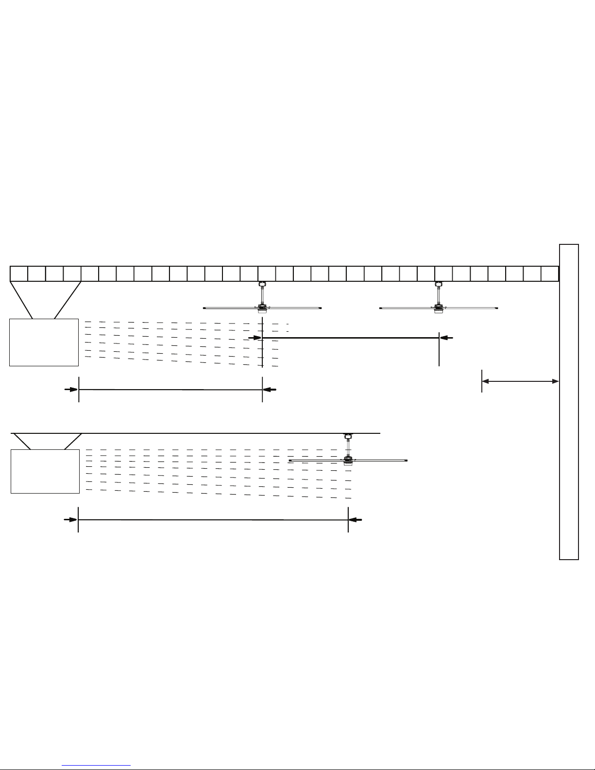
HVLS fans should not be located near to air supply outlets or exhausting inlets of other HVAC
equipment. Supply air outlets can be congured to deliver air away from the HVLS fan or the fan
location should be oriented such that the outlet is pointing away from the fan and outside the
swept area of the fan. Exhaust fan inlets or other return air points creating a negative pressure
should not be within 1.5 times the diameter of the fan. This system will diminish the capacity of
the HVLS fan. Proper systems orientation will provide an enhancement to the Indoor Air Quality
(IAQ) and occupant comfort. Refer to next page for illustration.
Page 8
© 2017 MacroAi r Technologies Toll Free: 866 668 3247 Fax : 909 890 2313 w ww.macr oair fans .com 7
Rev. Date 040 218
HVAC Diffuser
with airflow
UNDER fan
HVAC Diffuser
with airflow
ABOVE fan
Fan Placement & Clearance
space from diffuser
space from diffuser
at least 1.5 x diameter away from
intake/discharge
at least 2 x diameter away from intake/discharge
spacing between fans
space from
wall
at least 1.5 x
diameter away
from the wall
at least 3 x diameter of the fans apart
Page 9
© 2018 MacroAir Technologies Toll Free: 866 668 3247 Fax: 909 890 2 313 www.macroairfans.com 8
Rev. Date 040218
Fan Clearance - Universal Mount
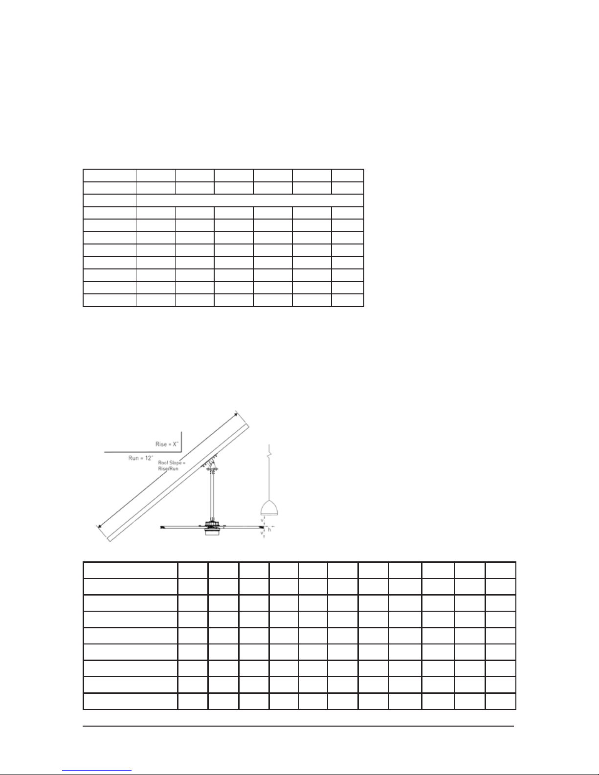
WARNING: FANS ARE NOT MEANT TO BE OPERATED IN WINDY CONDITIONS.
The Universal Mount can be used in any application but must always be used in windy
conditions, applications where wind may sometimes be present or where the total clearance
between the mount and the airfoils is greater than 10 feet. The minimum distance of a fan to a
wall or similar obstruction should be no less than 1.5 times the diameter of the fan.
Maximum Angle for Mount (feet)
Slope (in) 0 2/12 4/12 6/12 8/12 10/12
Roof Angle 0 9.5
o
18.4
o
26.6
o
33.7
o
39.8
o
Diameter Recommended Total Drop (Mount to Airfoil) Length (ft)
8 feet 3 3 3 3 4 5
10 feet 3 3 3 4 5 6
12 feet 3 3 3 5 6 7
14 feet 3 3 4 5 7 8
16 feet 3 3 4 6 7 9
18 feet 3 3 5 7 8 N/A*
20 feet 3 4 5 7 9 N/A*
24 feet 3 4 7 9 N/A* N/A*
*Drop lengths longer than 10 feet are not recommended
The drop lengths above are minimum recommendations only, based solely on roof pitch and
fan diameter. Other factors, such as allowing for proper airow into the fan must be evaluated
when determining drop length requirements. In addition, MacroAir strongly recommends that
the fan airfoils must be a minimum of 10 feet (3.05 meters) above the oor. Contact MacroAir for
assistance with fan placement and drop length selection (contact information can be found on
page 74).
The table below shows the clearance
needed from the fan to obstructions such
as lighting, conduit, etc.
Minimum Clearance (Horizontal / Vertical inches):
Airfoil / Drop Length (ft) 2 3 4 5 6 7 8 9 10 11 12
8 feet 7 / 7 7 / 7 7 / 7 7 / 7 8 / 8 8 / 8 9 / 8 11 / 9 13 / 10 N/A** N/A**
10 feet 7 / 7 7 / 7 7 / 8 7 / 8 8 / 8 8 / 9 9 / 9 11 / 10 13 / 11 N/A** N/A**
12 feet 7 / 8 7 / 8 7 / 8 7 / 9 8 / 9 8 / 10 9 / 10 11 / 11 13 / 12 N/A** N/A**
14 feet 7 / 9 7 / 9 7 / 9 7 / 10 8 / 10 8 / 11 9 / 12 11 / 12 13 / 13 N/A** N/A**
16 feet 7 / 10 7 / 10 7 / 11 7 / 11 8 / 12 8 / 12 9 / 13 11 / 14 13 / 15 N/A** N/A**
18 feet 7 / 12 7 / 12 7 / 12 7 / 13 8 / 13 8 / 14 9 / 15 11 / 16 13 / 17 N/A** N/A**
20 feet N/A 7 / 14 7 / 14 7 / 15 8 / 15 8 / 16 9 / 17 11 / 18 13 / 20 N/A** N/A**
24 feet N/A 7 / 19 7 / 19 7 / 20 8 / 21 8 / 22 9 / 23 11 / 24 13 / 26 N/A** N/A**
**Contact MacroAir if you require drop lengths greater than 10 ft
Page 10
© 2018 MacroAir Technologies Toll Free: 866 668 3247 Fax: 909 890 2 313 www.macroairfans.com 9
Rev. Date 040218
Fan Clearance - Rapid Mount Industrial
WARNING: FANS ARE NOT MEANT TO BE OPERATED IN WINDY CONDITIONS.
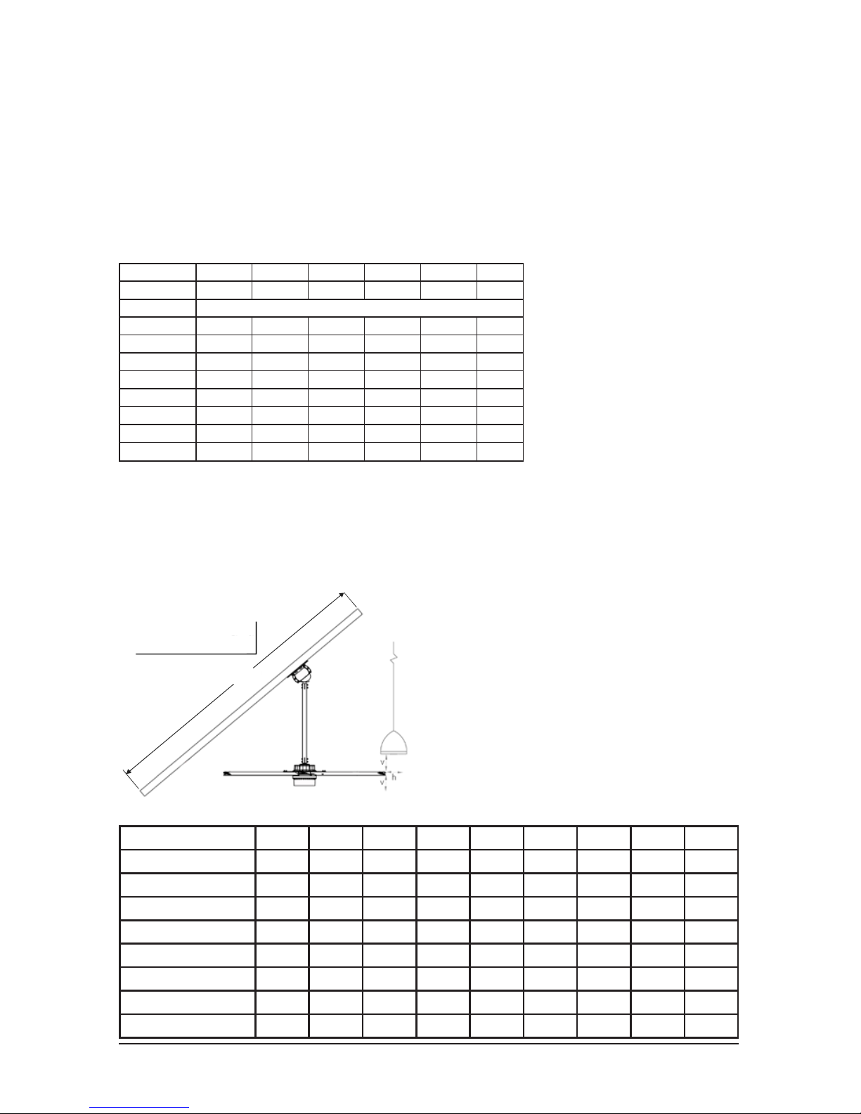
The Rapid Mount Industrial should only be used in applications where the total clearance
between the mount and the airfoils is less than 10 feet. Otherwise use a Universal Mount with
guy wires (refer to page 45). The minimum distance of a fan to a wall or similar obstruction
should be no less than 1.5 times the diameter of the fan.
Maximum Angle for Mount (feet)
Slope (in) 0 2/12 4/12 6/12 8/12 10/12
Roof Angle 0 9.5
o
18.4
o
26.6
o
33.7
o
39.8
o
Diameter Recommended Total Drop (Mount to Airfoil) Length (ft)
8 feet 3 3 3 4 5 6
10 feet 3 3 4 5 6 8
12 feet 3 3 5 6 7 9
14 feet 3 4 5 7 9 N/A*
16 feet 3 4 6 8 10 N/A*
18 feet 3 5 6 9 N/A* N/A*
20 feet 3 5 7 10 N/A* N/A*
24 feet 4 6 9 N/A* N/A* N/A*
*Need Universal Mount with guy wires
The table below shows the clearance
needed from the fan to obstructions such
as lighting, conduit, etc.
Minimum Clearance (Horizontal / Vertical inches):
Airfoil / Drop Length (ft) 2 3 4 5 6 7 8 9 10
8 feet 9 / 14 11 / 14 13 / 14 15 / 15 17 / 15 19 / 16 22 / 17 25 / 17 29 / 18
10 feet 9 / 16 11 / 16 13 / 17 15 / 17 17 / 18 19 / 18 22 / 19 25 / 20 29 / 21
12 feet 9 / 18 11 / 19 13 / 19 15 / 19 17 / 20 19 / 21 22 / 22 25 / 23 29 / 24
14 feet 9 / 21 11 / 21 13 / 22 15 / 22 17 / 23 19 / 24 22 / 25 25 / 26 29 / 27
16 feet 9 / 24 11 / 24 13 / 24 15 / 25 17 / 26 19 / 27 22 / 28 25 / 29 29 / 31
18 feet 9 / 27 11 / 27 13 / 28 15 / 28 17 / 29 19 / 30 22 / 31 25 / 33 29 / 34
20 feet N/A 11 / 31 13 / 31 15 / 32 17 / 33 19 / 34 22 / 35 25 / 37 29 / 38
24 feet N/A 11 / 39 13 / 40 15 / 20 17 / 42 19 / 43 22 / 44 25 / 46 29 / 48
The drop lengths above are minimum recommendations only, based solely on roof pitch and
fan diameter. Other factors, such as allowing for proper airow into the fan must be evaluated
when determining drop length requirements. In addition, MacroAir strongly recommends that
the fan airfoils must be a minimum of 10 feet (3.05 meters) above the oor. Contact Technical
Support for assistance with fan placement and drop length selection (Technical Support contact
information can be found on page 74).
Rise = X”
Run = 12”
Roof Slope =
Rise/Run
Page 11
© 2018 MacroAir Technologies Toll Free: 866 668 3247 Fax: 909 890 2 313 www.macroairfans.com 10
Rev. Date 040218
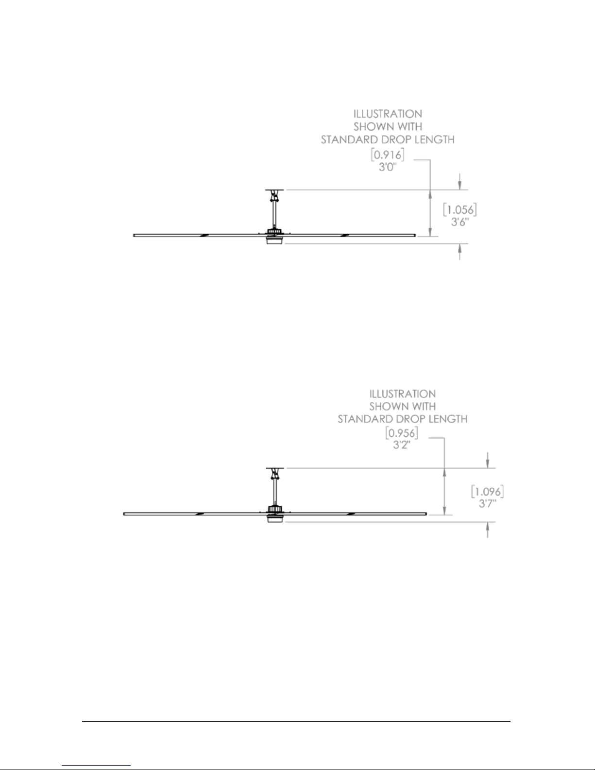
Model 550
The Model 550 has a standard airfoil to mount clearance of 3 feet [0.916 m] with the Rapid Mount
Industrial or Universal Mount. A clearance of 2 feet [0.6 m] is the minimum allowed clearance
for this fan model. Refer to the Fan Clearance & Placement charts on pages 6-9 for required fan
clearance and mounting conditions.
Model 780
The Model 780 has a standard airfoil to mount clearance of 3 feet - 2 inches [0.956 m] with the
Rapid Mount industrial or Universal Mount. A clearance less than this is not allowed. Refer to the
Fan Clearance & Placement charts on pages 6-9 for required fan clearance and mounting
conditions.
Fan Dimensions
Page 12
© 2018 MacroAir Technologies Toll Free: 866 668 3247 Fax: 909 890 2 313 www.macroairfans.com 11
Rev. Date 040218
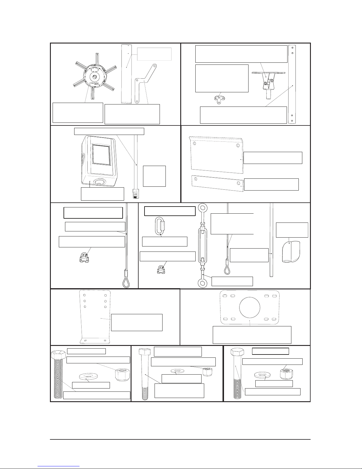
Airfoil Retainer
Link (6)
Airfoil (6)
AVD 550/780
Motor Unit (1)
I-Beam Shim (2)
I-Beam Clamp (2)
Extension Tube (1)
Universal Mount (1)
Guy Wire
Bracket (2)
Touchpad Digital
Remote (1)
Stranded Shielded CAT5e (1)
RJ45
Pin-Out
Type “B”
Guy Wire Assembly
Wire Rope (4)
19ft (A), 23ft (B),
or 33ft (C)
Turn Buckle (4)
1/4" Quicklink (4)
Wire Rope Clamp (8)
Wire Rope Clamp (2)
Safety Cable Parts
Wire Rope 3/16” (1)
Components (Universal Mount)
Guy Wire
Elastic Band (1)
Elastic Band
Clip (1)
Glulam Bracket (2)
(Optional)
Noise Dampening Pad (1)
(Optional)
5/16"-24 x 2" Hex Bolt (12)
5/16" Washer (24)
5/16"-24 Nylon Lock Nut (12)
6 Blade Bolt Kit
3/8" Washer (4)
3/8"-16 Nylon Lock Nut (4)
3/8"-16 x 2 3/4" Hex
Head Bolts (4)
3/8" Washer (8)
Extension Bolt Kit
1/2"-13 x 2 1/2" Hex Bolt (4)
1/2"-13 Nylon Lock Nut (4)
1/2" Washer (8)
I-Beam Bolt Kit
Make sure all parts listed above are included if you purchased the Universal Mount.
Read the entire manual before beginning the installation of the fan. Additional parts
may be required, including, but not limited to, guy wire attachment hardware, extra
cable, Unistrut, and bolts for Glulam mounting. Power cable is not provided.
Page 13
© 2018 MacroAir Technologies Toll Free: 866 668 3247 Fax: 909 890 2 313 www.macroairfans.com 12
Rev. Date 040218
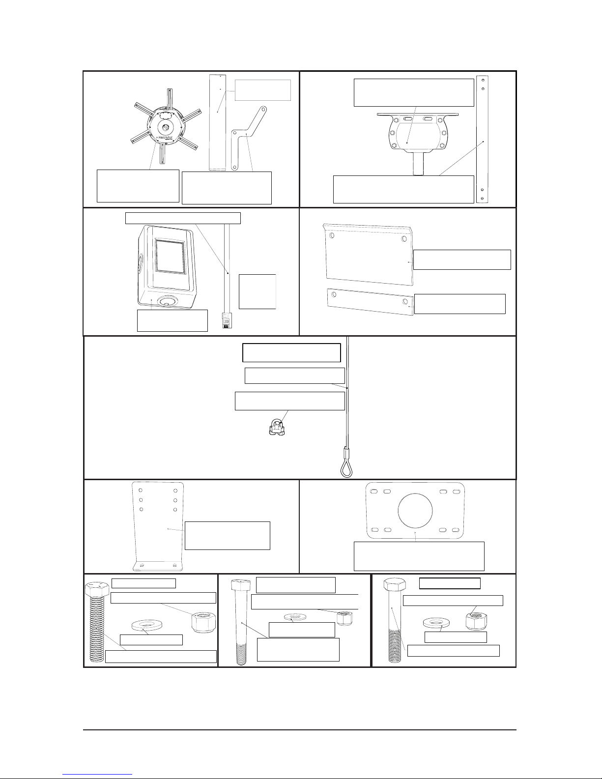
Rapid Mount (1)
Extension Tube (1)
Airfoil Retainer
Link (6)
Airfoil (6)
AVD 550/780
Motor Unit (1)
Glulam Bracket (2)
(Optional)
Noise Dampening Pad (1)
(Optional)
Touchpad Digital
Remote (1)
Stranded Shielded CAT5e (1)
RJ45
Pin-Out
Type “B”
Wire Rope Clamp (2)
Safety Cable Parts
Wire Rope 3/16” (1)
Components (Rapid Mount)
Make sure all parts listed above are included if you purchased the Rapid Mount
Industrial. Read the entire manual before beginning the installation of the fan. Additional
parts may be required, including, but not limited to, guy wire attachment hardware,
extra cable, Unistrut, and bolts for Glulam mounting. Power cable is not provided.
I-Beam Shim (2)
I-Beam Clamp (2)
5/16"-24 x 2" Hex Bolt (12)
5/16" Washer (24)
5/16"-24 Nylon Lock Nut (12)
6 Blade Bolt Kit
3/8" Washer (4)
3/8"-16 Nylon Lock Nut (4)
3/8"-16 x 2 3/4" Hex
Head Bolts (4)
3/8" Washer (8)
Extension Bolt Kit
1/2"-13 x 2 1/2" Hex Bolt (4)
1/2"-13 Nylon Lock Nut (4)
1/2" Washer (8)
I-Beam Bolt Kit
Page 14
© 2018 MacroAir Technologies Toll Free: 866 668 3247 Fax: 909 890 2 313 www.macroairfans.com 13
Rev. Date 040218
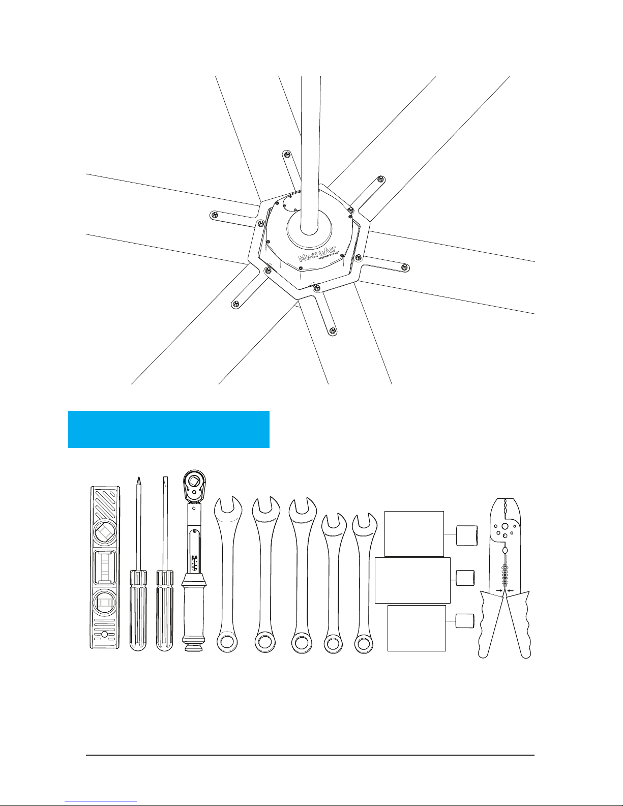
Fan Components and Tools
10 mm
3/4"
9/16"
1/2"
9/16
1/2
3/4
3/8
3/4
9/16
1/2
Tools Required:
Note: A drill and drill bits
will also be required when
mounting to Glulams
Page 15
© 2018 MacroAir Technologies Toll Free: 866 668 3247 Fax: 909 890 2 313 www.macroairfans.com 14
Rev. Date 040218
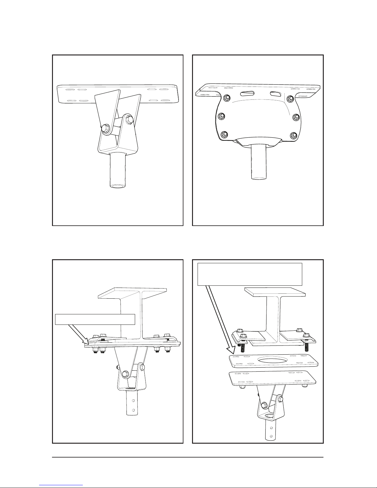
Mounts
Noise Dampening Pad
Place Noise Dampening Pad between
mount and mounting surface
for all mounts and mounting styles
Universal Mount
Turn to page 15
Rapid Mount
Turn to page 30
WARNING: Do not disassemble
the inner portion (ball) of the
mount for any reason.
If you purchased the Noise/Vibration Dampening Pad (optional):
Page 16
© 2018 MacroAir Technologies Toll Free: 866 668 3247 Fax: 909 890 2 313 www.macroairfans.com 15
Rev. Date 040218
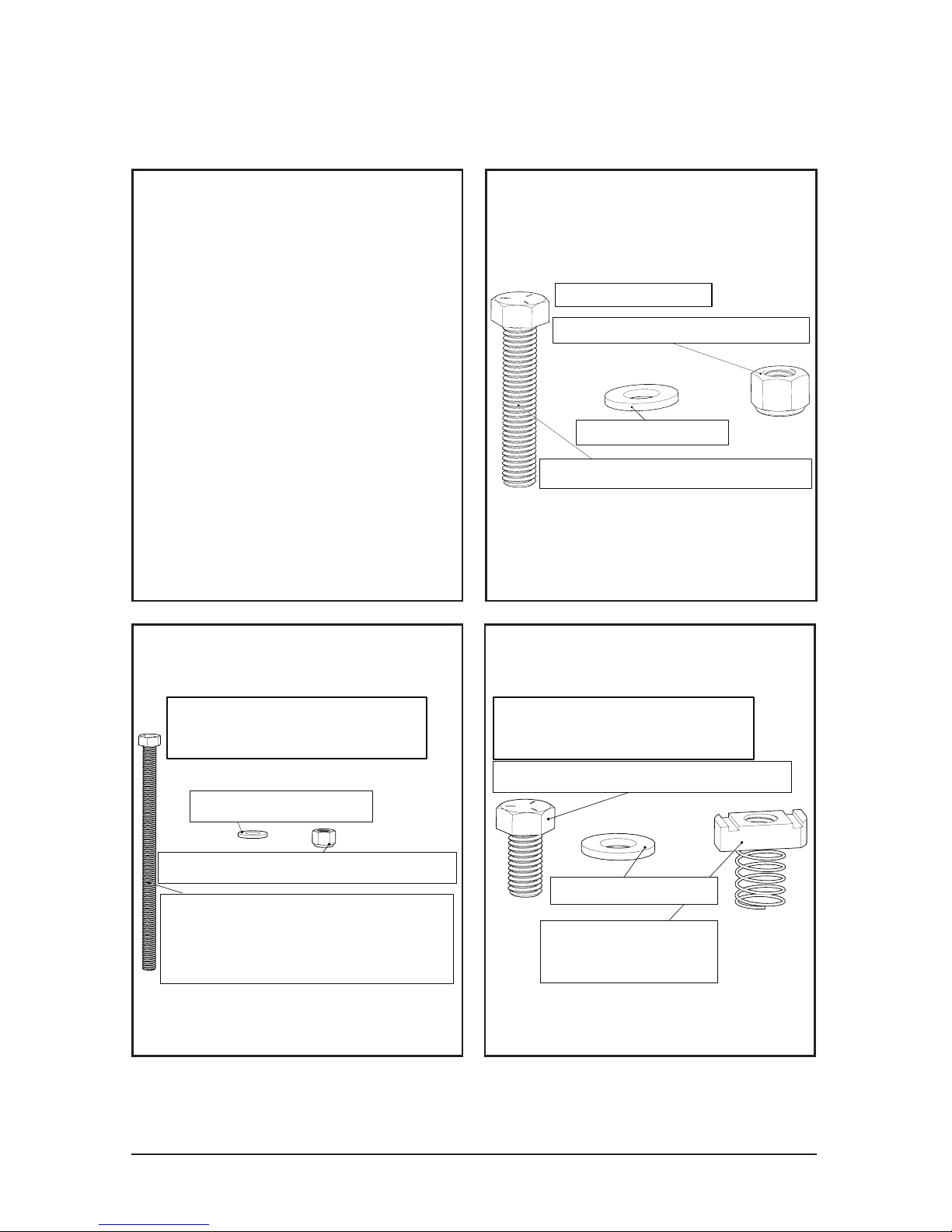
1. All Universal Mounts
1.1 Mounting Bolt Kits
1/2"-13 Grade 5 Hex Bolt
at least 2 1/2" longer than
width of Glulam (2)
1/2" Washer (4)
1/2"-13 Nylon Lock Nut (2)
Glulam Required Parts
(NOT PROVIDED)
1/2"-13 x 2 1/2" Hex Bolt (4)
1/2"-13 Nylon Lock Nut (4)
1/2" Washer (8)
I-Beam Bolt Kit
1/2"-13 x 1 1/2" Hex Bolt (4)
1/2"-13 Unistrut
Spring Nut (4)
Unistrut Required Parts
(NOT PROVIDED)
1/2" Washer (4)
The I-Beam Bolt Kit is included
in the shipment of all fans.
Additional parts must be
purchased if mounting to a
Glulam or Unistrut.
For mounting to steel trusses
over 3 inches in width, use the
I-Beam mounting. For widths
under 3 inches, use Unistrut
span mounting. If you wish to
mount to a different surface
than these listed here, contact
a structural engineer.
Universal Mount I-Beam mounting starts on page 16
Universal Mount Glulam mounting starts on page 18
Universal Mount Unistrut mounting starts on page 20
Page 17
© 2018 MacroAir Technologies Toll Free: 866 668 3247 Fax: 909 890 2 313 www.macroairfans.com 16
Rev. Date 040218
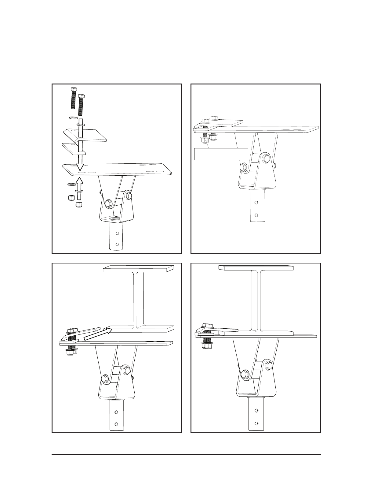
Hand Tighten
Use this method for steel trusses and I-Beams over 3” in width.
1.1.1 Universal Mount
I-Beam (Steel Truss Mounting)
Page 18
© 2018 MacroAir Technologies Toll Free: 866 668 3247 Fax: 909 890 2 313 www.macroairfans.com 17
Rev. Date 040218
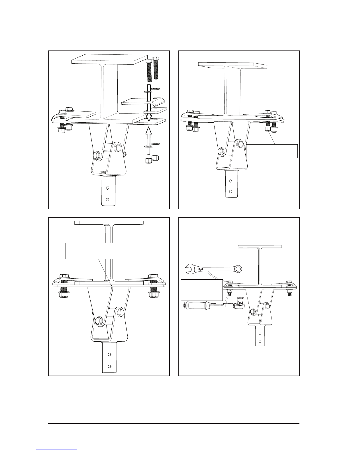
1.1.1 Universal Mount I-Beam
Center the Mount
Hand Tighten
75 ft-lbs
[102 N-m]
Complete I-Beam mount installation and turn to page 22
3/4”
Page 19
© 2018 MacroAir Technologies Toll Free: 866 668 3247 Fax: 909 890 2 313 www.macroairfans.com 18
Rev. Date 040218
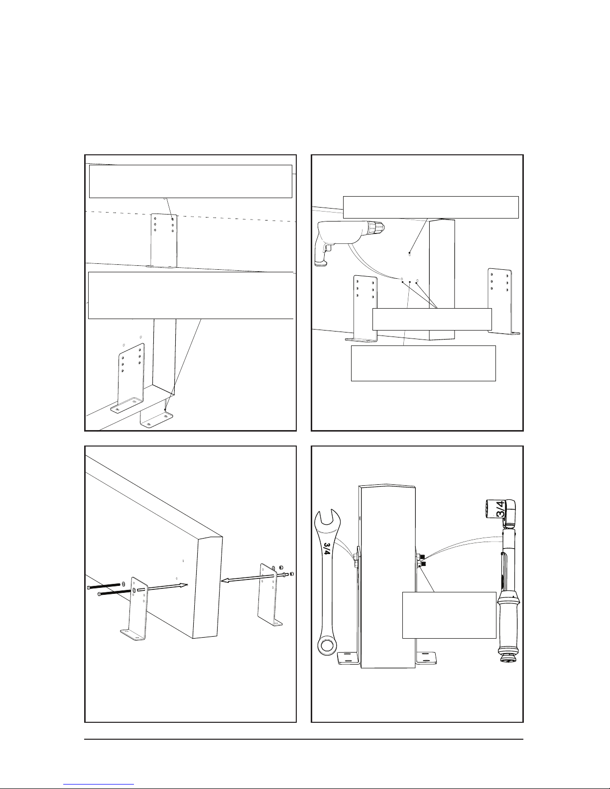
Use the two holes closest to
the center line of the glulam.
3/16" safety cable clearance
Holes can be oversized
for leveling the mount
1/2" bolt clearance
75 ft lbs
75 ft-lbs
[102 N-m]
The bracket can be below the bottom
of the glulam if necessary but
is not recomended if it is avoidable.
This method is recommended for Glulams or wood beams 5-1/8” or
wider. For narrower beams, span across two or more beams using the
Unistrut mounting method.
1.1.2 Universal Mount Glulam
Page 20
© 2018 MacroAir Technologies Toll Free: 866 668 3247 Fax: 909 890 2 313 www.macroairfans.com 19
Rev. Date 040218
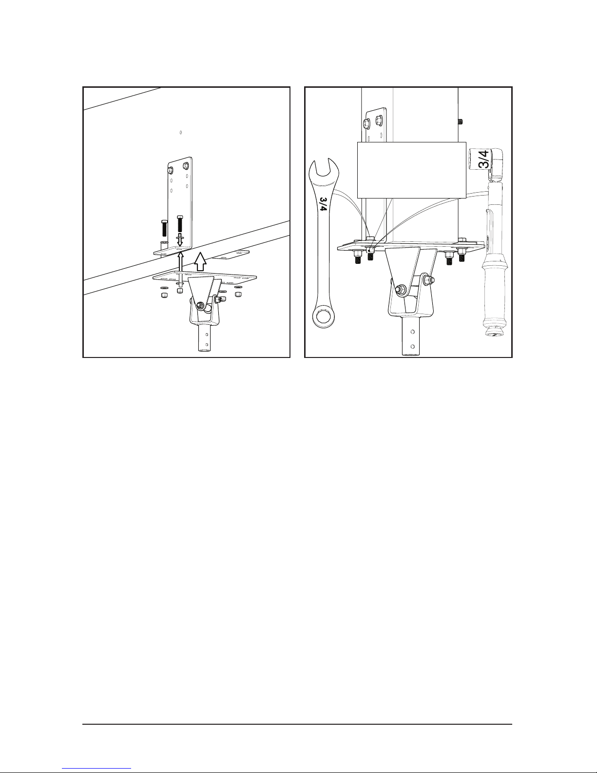
75 ft-lbs
75 ft-lbs
[102 N-m]
1.1.2 Universal Mount Glulam
Complete Glulam mount installation and turn to page 22
Page 21

© 2018 MacroAir Technologies Toll Free: 866 668 3247 Fax: 909 890 2 313 www.macroairfans.com 20
Rev. Date 040218
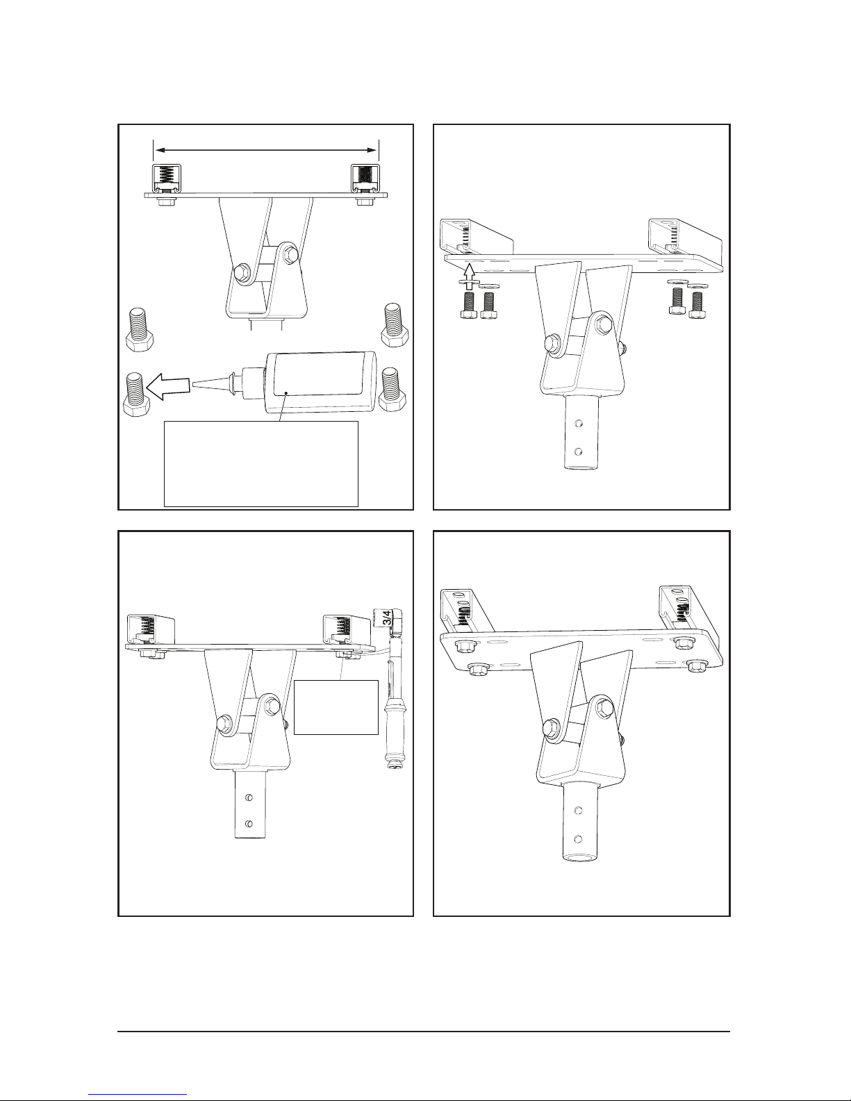
This method is used to span components of a
building structure. Attachment points to the
building structure can vary greatly, so we
recommend contacting Unistrut so they can
recommend the best method for attaching the
Unistrut (www.unistrut.us).
If the spanning distance is greater than 8 feet,
please consult a Structural Engineer. Please
refer to page 4 for the maximum torque and
weight values.
NOTE: Mounting to C- and Z-purlins requires Unistrut span
mounting. Mounting to trusses under three (3) inches in width
requires two or more trusses to be linked with Unistrut.
1.1.3 Universal Mount Unistrut
Page 22
© 2018 MacroAir Technologies Toll Free: 866 668 3247 Fax: 909 890 2 313 www.macroairfans.com 21
Rev. Date 040218
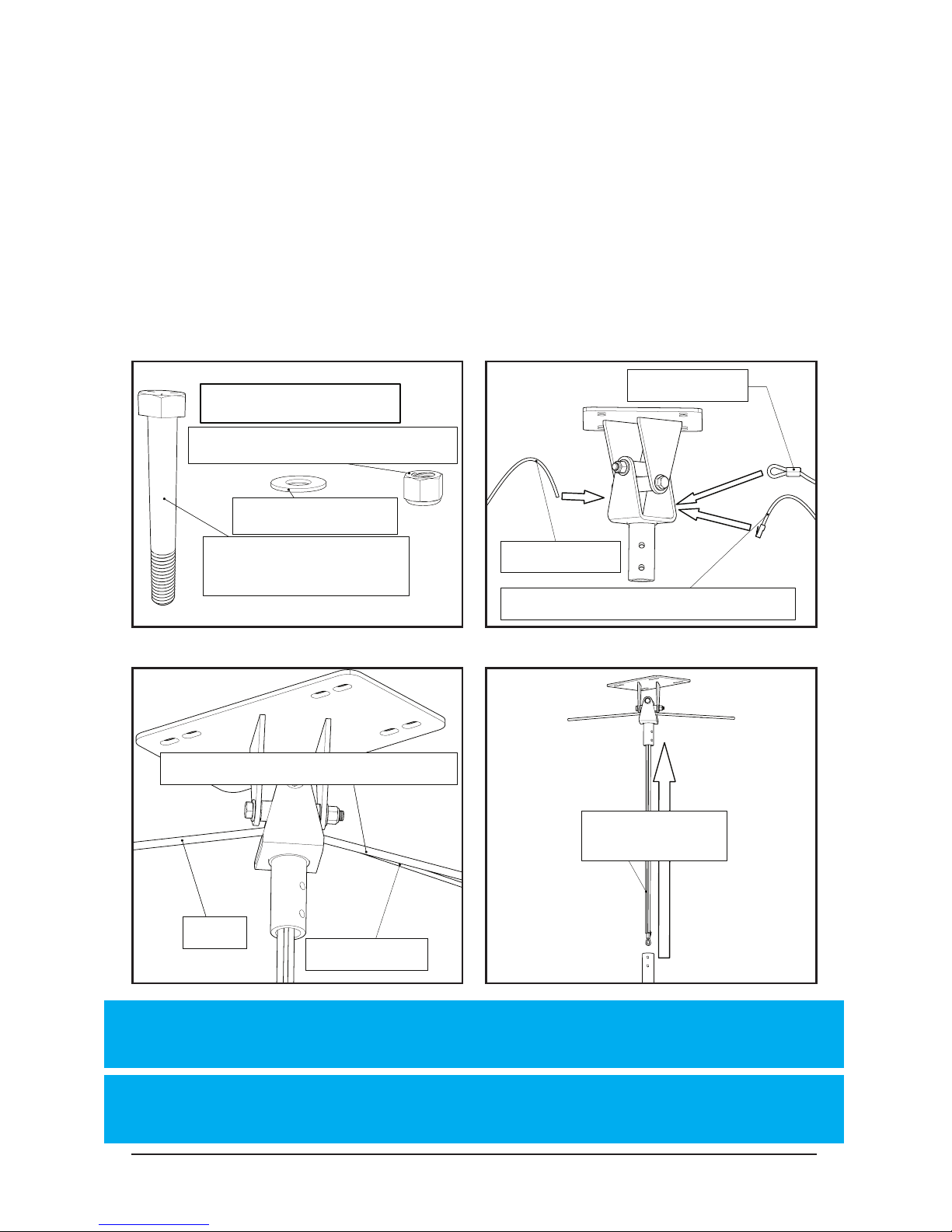
1.1.3 Universal Mount Unistrut
Loctite 243
recomended
Loctite 243
recomended
50 ft-lbs
50 ft-lbs
[68 N-m]
Complete Unistrut mount installation and turn to page 22
Minimum 1-5/8” Unistrut
Unpierced Channels (P1000
or P1001B)
12-7/8”
3/4”
Page 23
© 2018 MacroAir Technologies Toll Free: 866 668 3247 Fax: 909 890 2 313 www.macroairfans.com 22
Rev. Date 040218
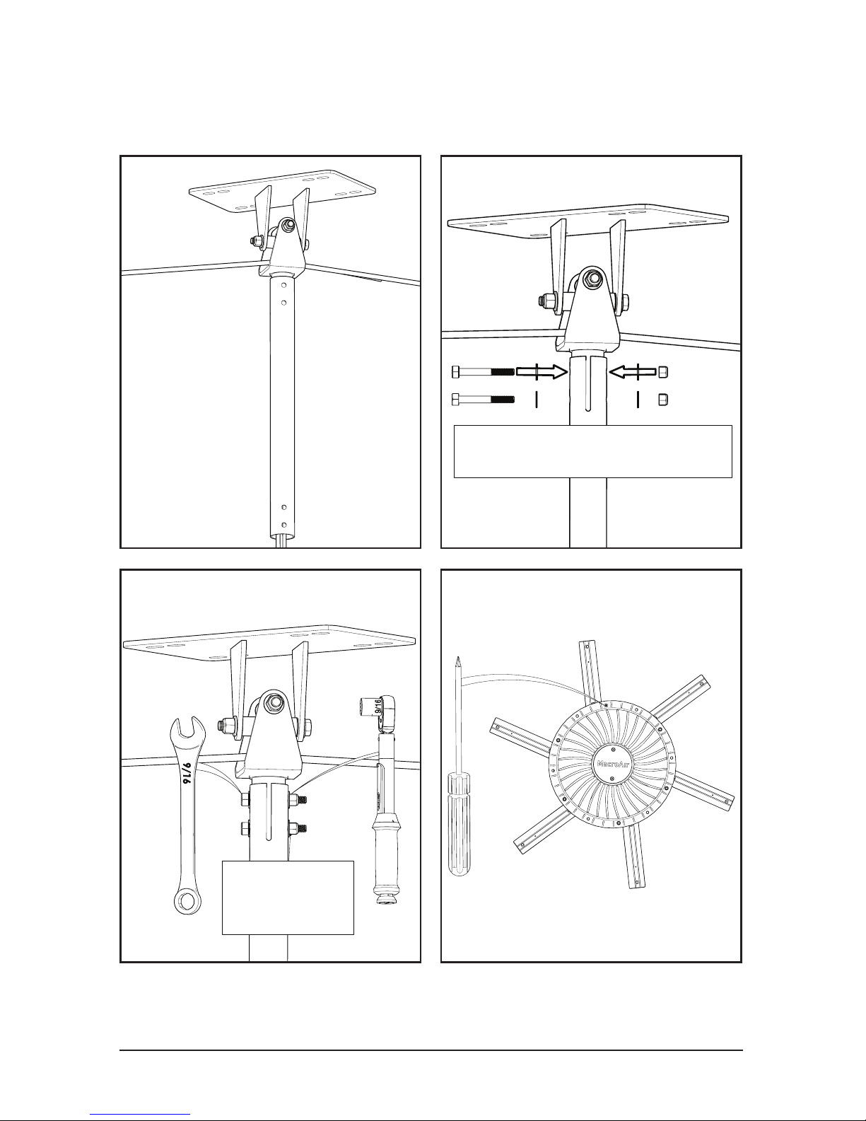
1.2 All Universal Mounts
Extension Tube
3/8" Washer (4)
3/8"-16 Nylon Lock Nut (4)
3/8"-16 x 2 3/4" Hex
Head Bolts (4)
3/8" Washer (8)
Extension Bolt Kit
Safety Cable
Power
Sheilded Stranded CAT5e Cable
Safety Cable
Power
Shielded Stranded CAT5e Cable
Safety Cable
Power Cable
Safety Cable
Power Cable
Shielded Stranded CAT5e Cable
Pull excess cable
through mount
Before Continuing:
1. Run the power cable to the mounting location.
2. Run the shielded CAT5e cable from the controller to the mount.
3. The communications cable MUST be routed at least 1 foot away
from power cables, high voltage power wires, and uorescent lighting.
The only point where the power cable should be near the comm wire is
when they are in the mount and extension tube.
CAT5e Shielded must be used at a minimum. No unshielded comm cables.
NOTE: Power cable must be routed into the mount on the
opposite side from safety cable and CAT5e cable.
NOTE: For networks, please refer to the network controller or
AirLynk manual for CAT5e wiring instructions.
Page 24
© 2018 MacroAir Technologies Toll Free: 866 668 3247 Fax: 909 890 2 313 www.macroairfans.com 23
Rev. Date 040218
1.2 All Universal Mounts
Extension Tube
30 ft-lbs
[41 N-m]
Be careful of wires
Page 25
© 2018 MacroAir Technologies Toll Free: 866 668 3247 Fax: 909 890 2 313 www.macroairfans.com 24
Rev. Date 040218
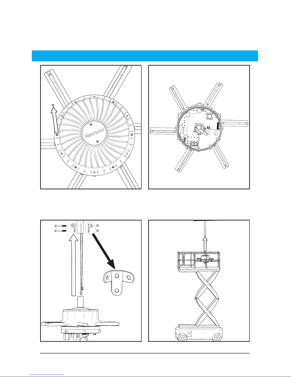
6x
Remove six (6) screws and the bottom cover. Be careful not to damage
the electrical components with the cover removed.
Two people can lift the fan if a lift is not available.
1.3 All Universal Mounts
Motor Unit
WARNING: The fan must be lifted by the struts. Do NOT lift the fan by the drive.
Must use Guy Wire Brackets when installing the Universal Mount
Page 26
© 2018 MacroAir Technologies Toll Free: 866 668 3247 Fax: 909 890 2 313 www.macroairfans.com 25
Rev. Date 040218
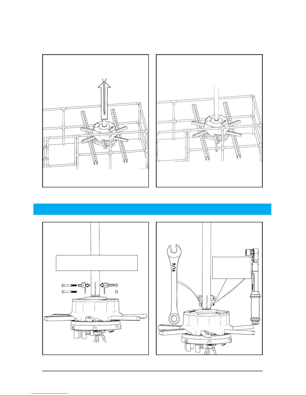
Be careful of wires
30 ft-lbs
30 ft-lbs
[41 N-m]
Carefully guide the motor shaft into the extension tube.
CAUTION: Do not put force onto the building with the lift.
9/16”
1.3 All Universal Mounts
Motor Unit
Page 27
© 2018 MacroAir Technologies Toll Free: 866 668 3247 Fax: 909 890 2 313 www.macroairfans.com 26
Rev. Date 040218
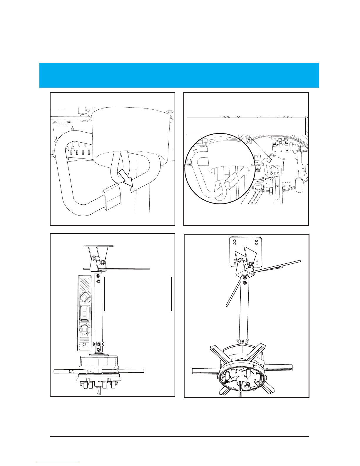
Ensure the
fan is level
Do not bend rubber bootDo not bend rubber boot
WARNING: Do not put too much tension on the safety cable. This will
deform the rubber boot and hinder the proper cooling of the motor.
1.3 All Universal Mounts
Motor Unit
Universal Mount I-Beam safety cable starts on page 27
Universal Mount Glulam safety cable starts on page 28
Universal Mount Unistrut safety cable starts on page 29
Page 28
© 2018 MacroAir Technologies Toll Free: 866 668 3247 Fax: 909 890 2 313 www.macroairfans.com 27
Rev. Date 040218
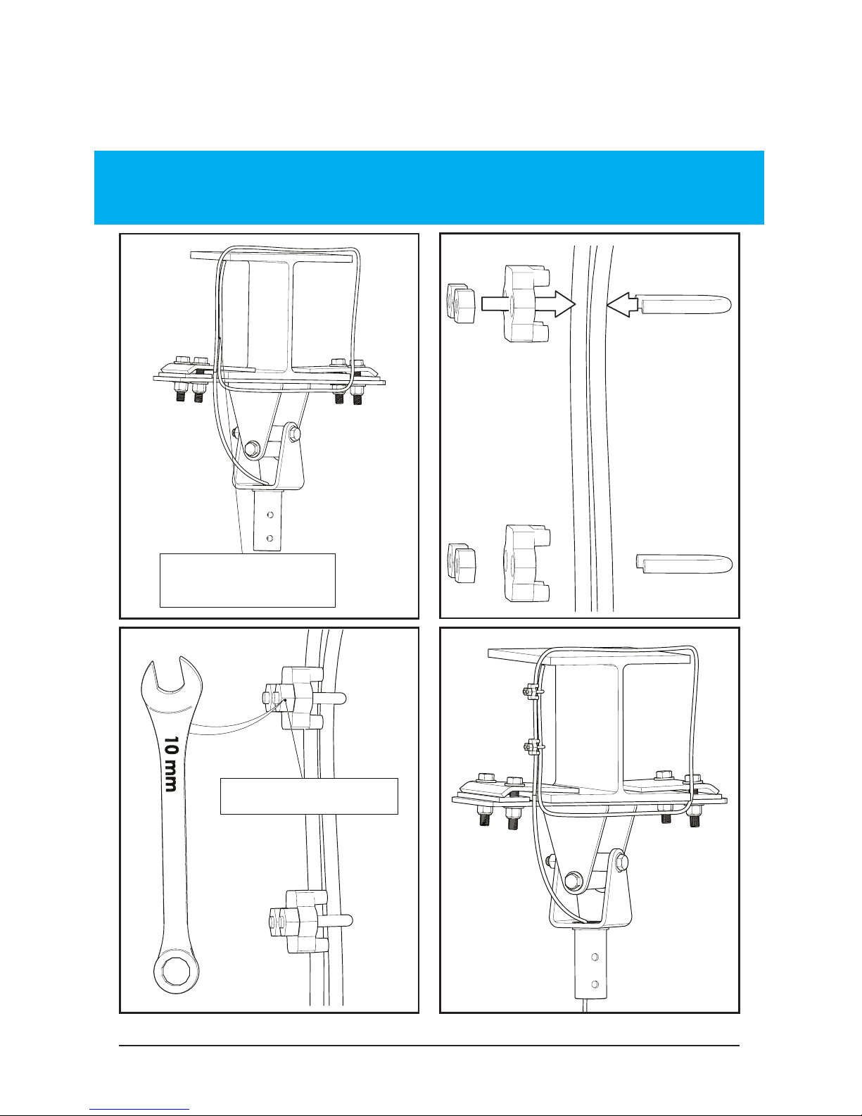
1.4.1 Universal Mount
I-Beam Safety Cable
Run safety cable
around I-Beam
Tighten both nuts
WARNING: Do not put too much tension on the safety cable. There needs
to be a small amount of slack present in the safety cable for proper
functioning. Avoid sharp edges.
Complete safety cable installation and turn to page 45
Page 29
© 2018 MacroAir Technologies Toll Free: 866 668 3247 Fax: 909 890 2 313 www.macroairfans.com 28
Rev. Date 040218
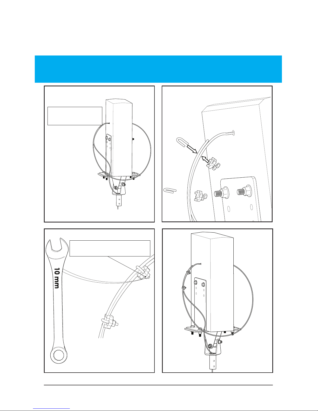
1.4.2 Universal Mount
Glulam Safety Cable
Tighten both nutsTighten both nuts
Run safety cable
Run safety cable
though hole
WARNING: Do not put too much tension on the safety cable. There
needs to be a small amount of slack present in the safety cable for
proper functioning. Avoid sharp edges.
Complete safety cable installation and turn to page 45
Page 30

© 2018 MacroAir Technologies Toll Free: 866 668 3247 Fax: 909 890 2 313 www.macroairfans.com 29
Rev. Date 040218
1.4.3 Universal Mount
Unistrut Safety Cable
The safety cable must be securely attached to the
building structure and NOT the unistrut. It can be
attached to I-beams, steel trusses, or Glulams
as shown in sections 1.4.1 and 1.4.2. Avoid sharp
edges. If you are unsure how to secure the safety
cable properly, contact a structural engineer.
Complete safety cable installation and turn to page 45
Page 31
© 2018 MacroAir Technologies Toll Free: 866 668 3247 Fax: 909 890 2 313 www.macroairfans.com 30
Rev. Date 040218
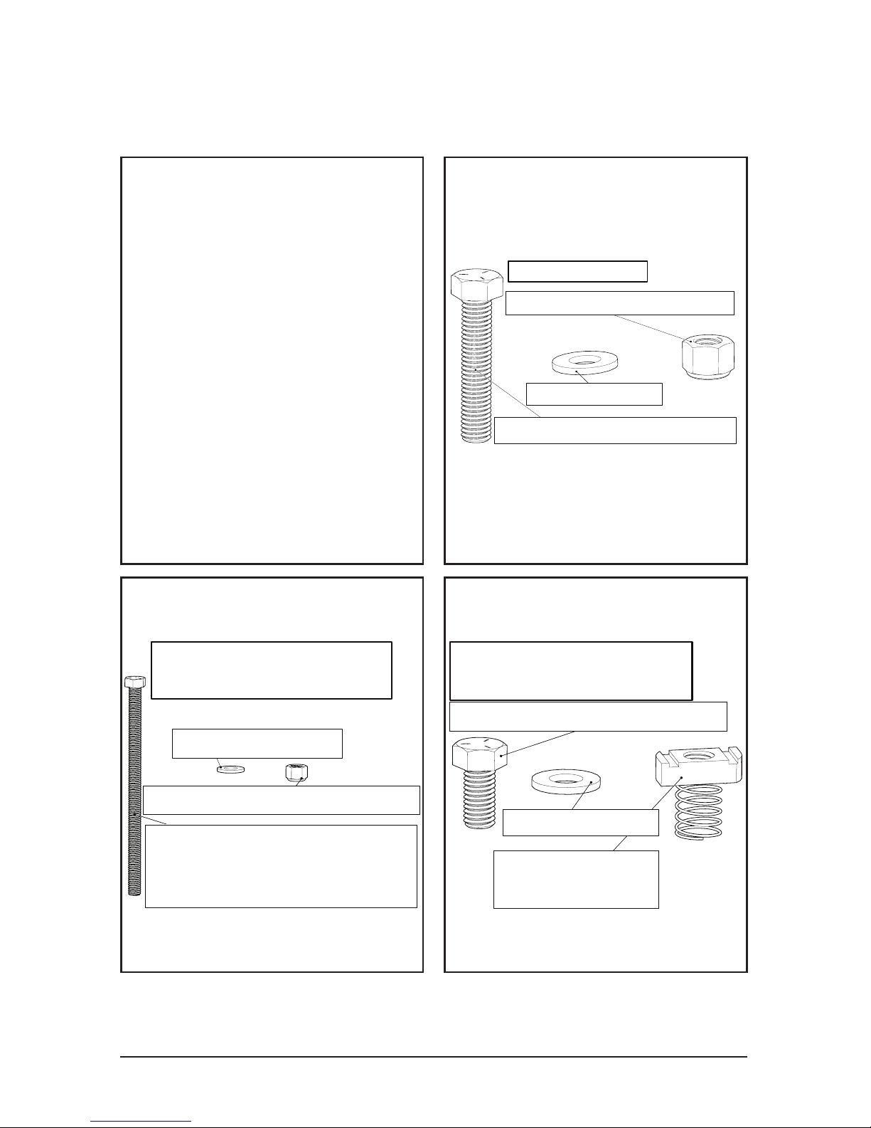
1/2"-13 Grade 5 Hex Bolt
at least 2 1/2" longer than
width of Glulam (2)
1/2" Washer (4)
1/2"-13 Nylon Lock Nut (2)
Glulam Required Parts
(NOT PROVIDED)
1/2"-13 x 2 1/2" Hex Bolt (4)
1/2"-13 Nylon Lock Nut (4)
1/2" Washer (8)
I-Beam Bolt Kit
1/2"-13 x 1 1/2" Hex Bolt (4)
1/2"-13 Unistrut
Spring Nut (4)
Unistrut Required Parts
(NOT PROVIDED)
1/2" Washer (4)
The I-Beam Bolt Kit is included
in the shipment of all fans.
Additional parts must be
purchased if mounting to a
Glulam or Unistrut.
For mounting to steel trusses
over 3 inches in width, use the
I-Beam mounting. For widths
under 3 inches, use Unistrut
span mounting. If you wish to
mount to a different surface
than these listed here, contact
a structural engineer.
I-Beam mounting starts on page 31
Glulam mounting starts on page 33
Unistrut mounting starts on page 35
2. All Rapid Mounts Industrial
2.1 Mounting Bolt Kits
Page 32
© 2018 MacroAir Technologies Toll Free: 866 668 3247 Fax: 909 890 2 313 www.macroairfans.com 31
Rev. Date 040218
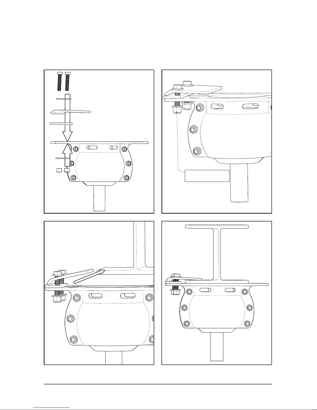
2.1.1 Rapid Mount Industrial
I-Beam (Steel Truss Mounting)
Hand Tighten
Use this method for steel trusses and I-beams over 3” in width.
Page 33
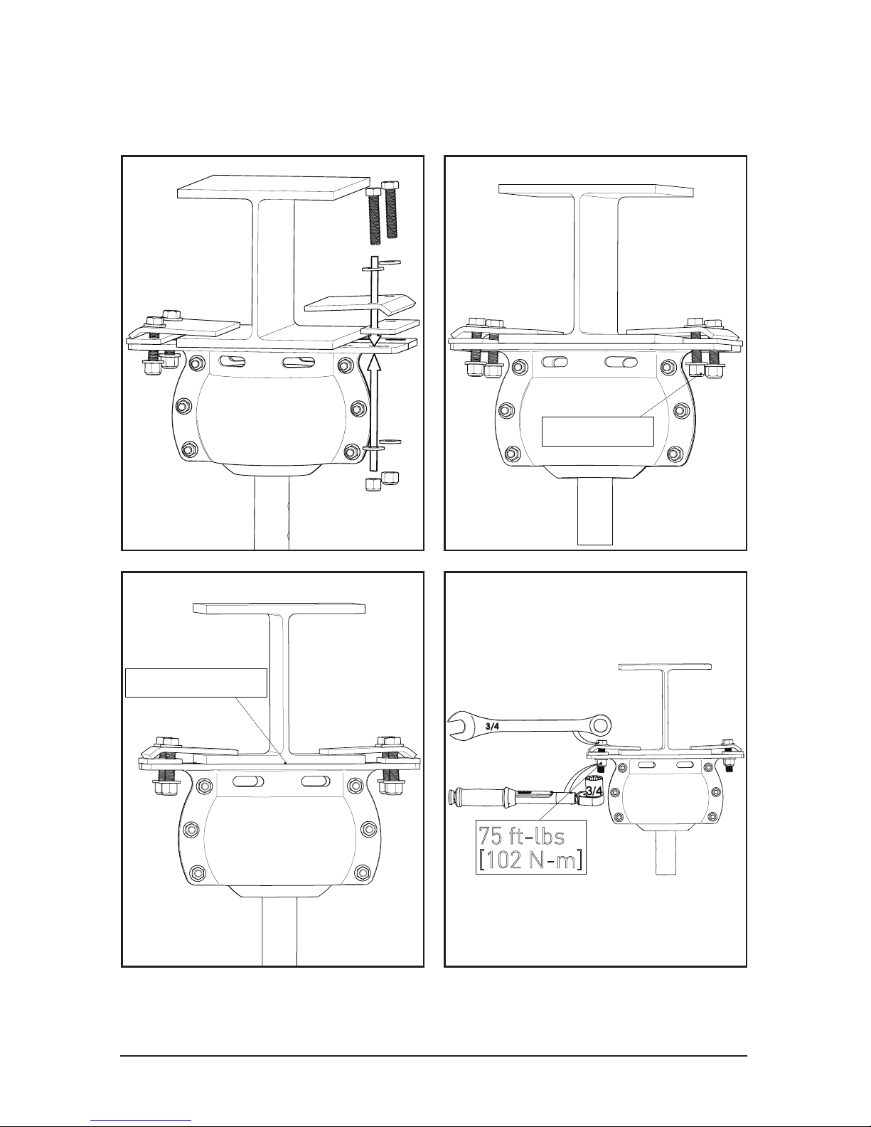
© 2018 MacroAir Technologies Toll Free: 866 668 3247 Fax: 909 890 2 313 www.macroairfans.com 32
Rev. Date 040218
Hand Tighten
75 ft-lbs
75 ft-lbs
[102 N-m]
Center the Mount
2.1.1 Rapid Mount Industrial
I-Beam
Complete Rapid Mount I-Beam installation and turn to page 37
Page 34
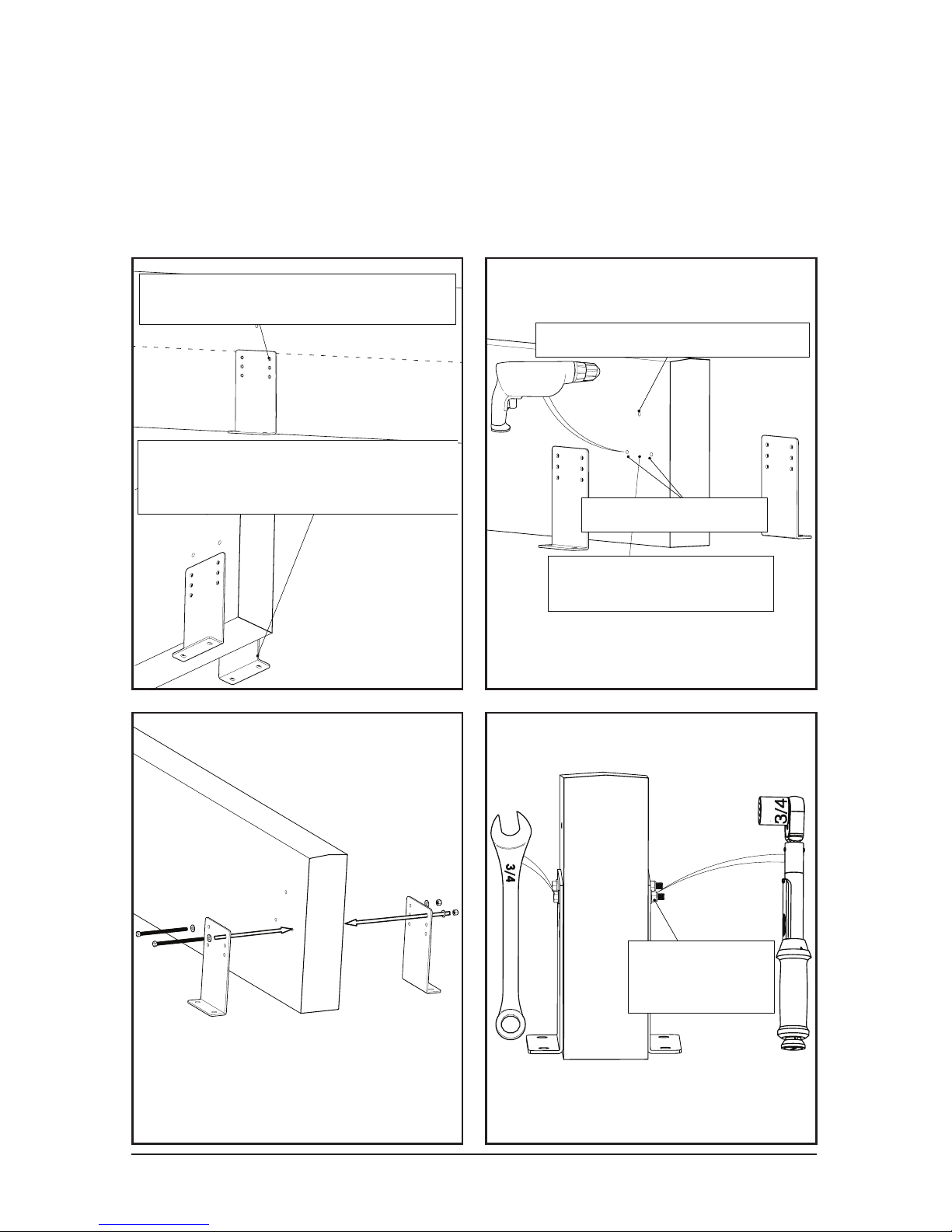
© 2018 MacroAir Technologies Toll Free: 866 668 3247 Fax: 909 890 2 313 www.macroairfans.com 33
Rev. Date 040218
Use the two holes closest to
the center line of the glulam.
3/16" safety cable clearance
Holes can be oversized
for leveling the mount
1/2" bolt clearance
75 ft lbs
75 ft-lbs
[102 N-m]
The bracket can be below the bottom
of the glulam if necessary but
is not recomended if it is avoidable.
This method is recommended for Glulams or wood beams 5-1/8” or
wider. For narrower beams, span across two or more beams using the
Unistrut mounting method.
2.1.2 Rapid Mount Industrial
Glulam
Page 35
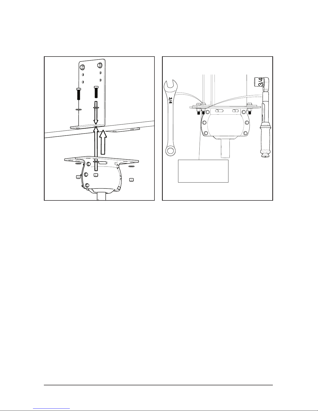
© 2018 MacroAir Technologies Toll Free: 866 668 3247 Fax: 909 890 2 313 www.macroairfans.com 34
Rev. Date 040218
75 ft-lbs
75 ft-lbs
[102 N-m]
Complete Rapid Mount Glulam installation and turn to page 37
2.1.2 Rapid Mount Industrial
Glulam
3/4”
Page 36

© 2018 MacroAir Technologies Toll Free: 866 668 3247 Fax: 909 890 2 313 www.macroairfans.com 35
Rev. Date 040218
This method is used to span components of a
building structure. Attachment points to the
building structure can vary greatly, so we
recommend contacting Unistrut so they can
recommend the best method for attaching the
Unistrut (www.unistrut.us).
If the spanning distance is greater than 8 feet,
please consult a Structural Engineer. Please refer
to page 4 for the maximum torque and weight
values.
2.1.3 Rapid Mount Industrial
Unistrut
NOTE: Mounting to C- and Z-purlins requires Unistrut span
mounting. Mounting to trusses under three (3) inches in width
requires two or more trusses to be linked with Unistrut.
Page 37
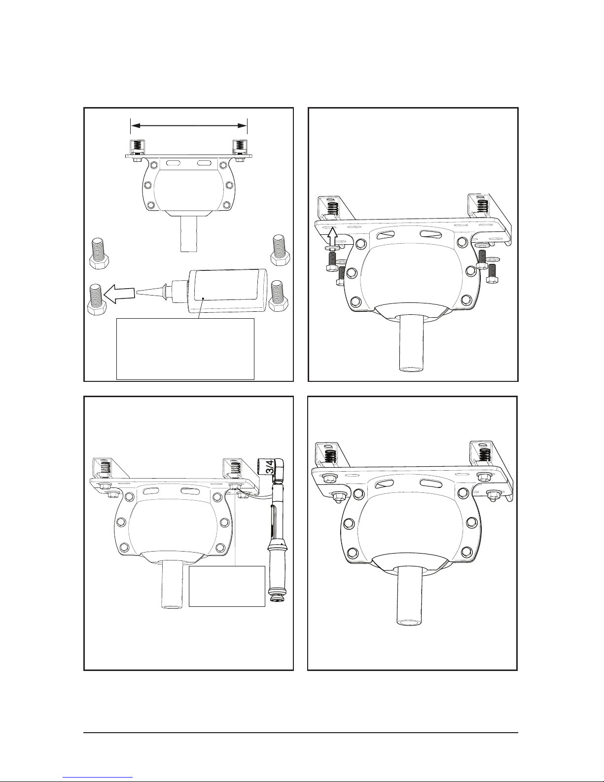
© 2018 MacroAir Technologies Toll Free: 866 668 3247 Fax: 909 890 2 313 www.macroairfans.com 36
Rev. Date 040218
2.1.3 Rapid Mount Industrial
Unistrut
50 ft-lbs
50 ft-lbs
[68 N-m]
Loctite 243
recomended
Loctite 243
recomended
12-7/8”
Complete Rapid Mount Unistrut installation and turn to page 37
Minimum 1-5/8” Unistrut
Unpierced Channels (P1000
or P1001B)
Page 38
© 2018 MacroAir Technologies Toll Free: 866 668 3247 Fax: 909 890 2 313 www.macroairfans.com 37
Rev. Date 040218
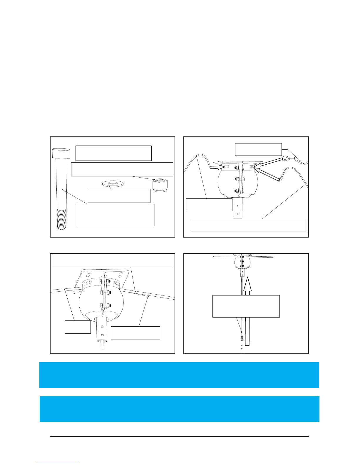
3/8" Washer (4)
3/8"-16 Nylon Lock Nut (4)
3/8"-16 x 2 3/4" Hex
Head Bolts (4)
3/8" Washer (8)
Extension Bolt Kit
Safety Cable
Power
Sheilded Stranded CAT5e Cable
Safety Cable
Power
Shielded Stranded CAT5e Cable
Pull excess cable
through mount
2.2 All Rapid Mounts Industrial
Extension Tube
Safety Cable
Sheilded Stranded CAT5e Cable
Power Cable
Safety Cable
Shielded Stranded CAT5e Cable
Power Cable
Before Continuing:
1. Run the power cable to the mounting location.
2. Run the shielded CAT5e cable from the controller to the mount.
3. The communications cable MUST be routed at least 1 foot away
from power cables, high voltage power wires, and uorescent lighting.
The only point where the power cable should be near the comm wire is
when they are in the mount and extension tube.
CAT5e Shielded must be used at a minimum. No unshielded comm cables.
NOTE: Power cable must be routed into the mount on the
opposite side from safety cable and CAT5e cable.
NOTE: For networks, please refer to the network controller or
AirLynk manual for CAT5e wiring instructions.
Page 39
© 2018 MacroAir Technologies Toll Free: 866 668 3247 Fax: 909 890 2 313 www.macroairfans.com 38
Rev. Date 040218
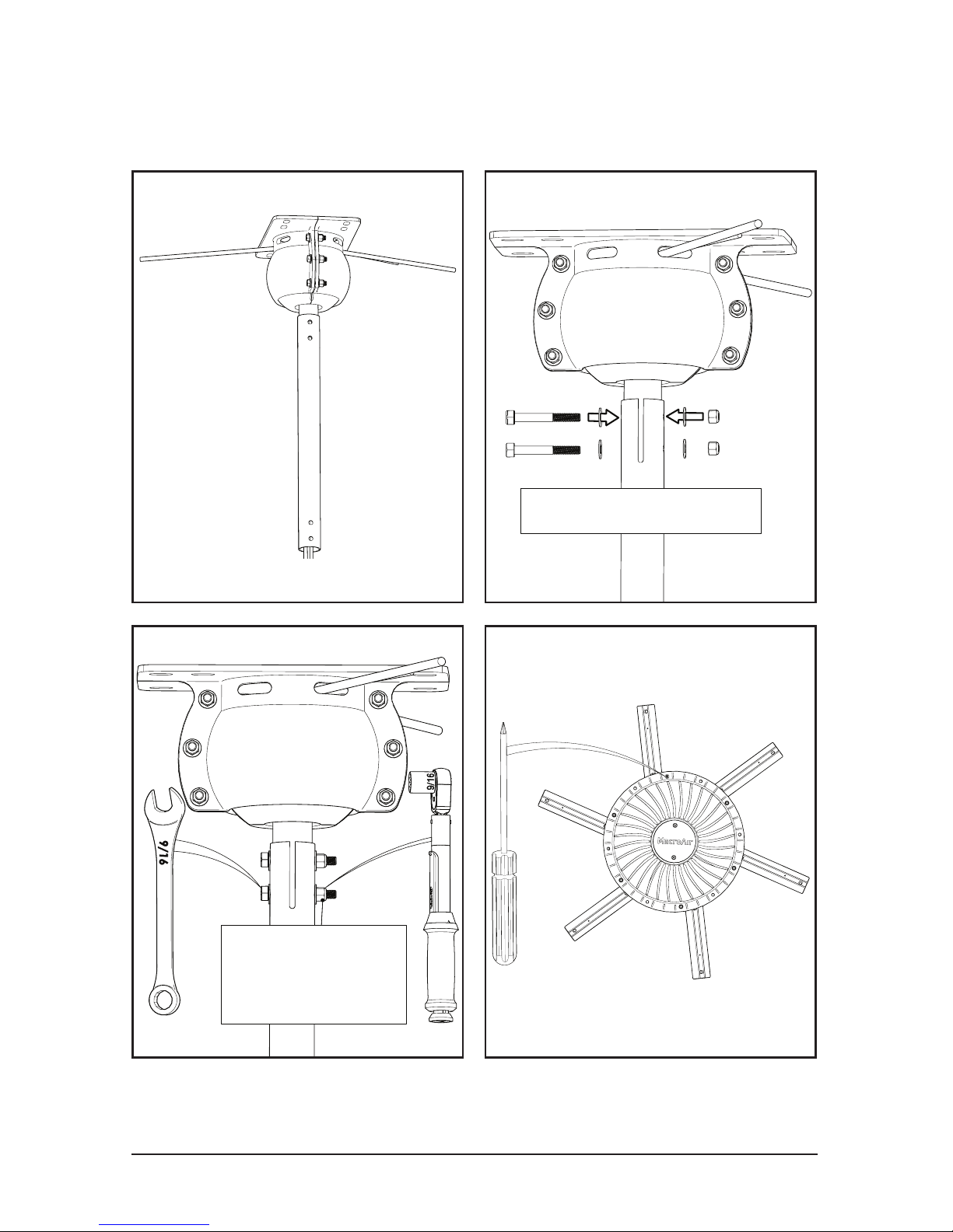
30 ft-lbs
30 ft-lbs
[41 N-m]
Be careful of wires
9/16”
2.2 All Rapid Mounts Industrial
Extension Tube
Page 40
© 2018 MacroAir Technologies Toll Free: 866 668 3247 Fax: 909 890 2 313 www.macroairfans.com 39
Rev. Date 040218
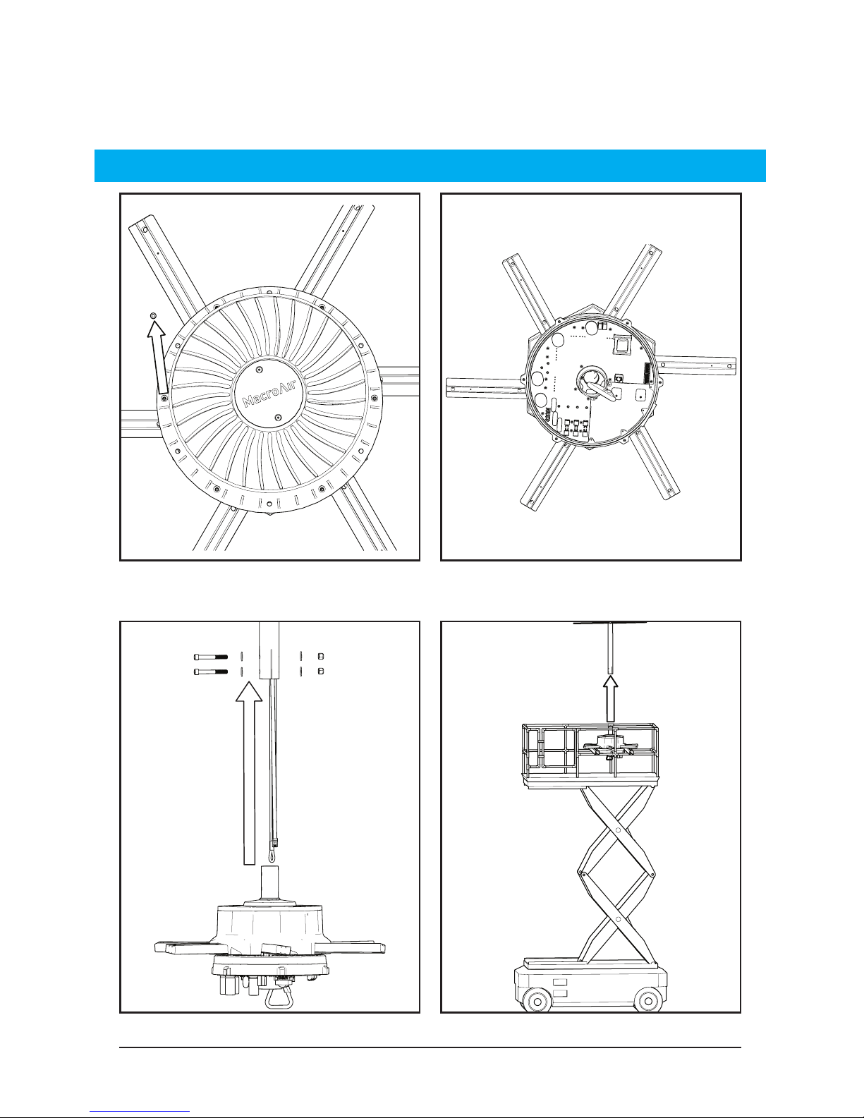
2.3 All Rapid Mounts Industrial
Motor Unit
6x
Remove six (6) screws and the bottom cover. Be careful not to damage
the electrical components with the cover removed.
Two people can lift the fan if a lift is not available.
WARNING: The fan must be lifted by the struts. Do NOT lift the fan by the drive.
Page 41
© 2018 MacroAir Technologies Toll Free: 866 668 3247 Fax: 909 890 2 313 www.macroairfans.com 40
Rev. Date 040218
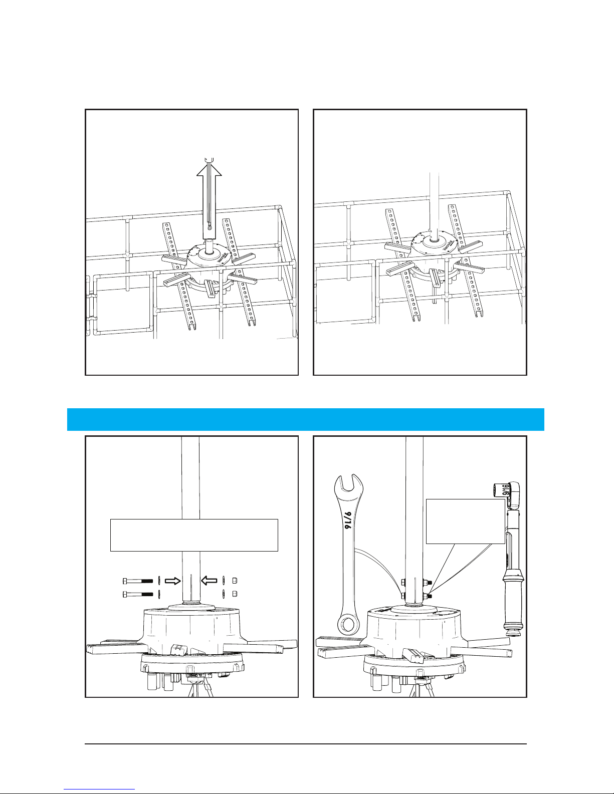
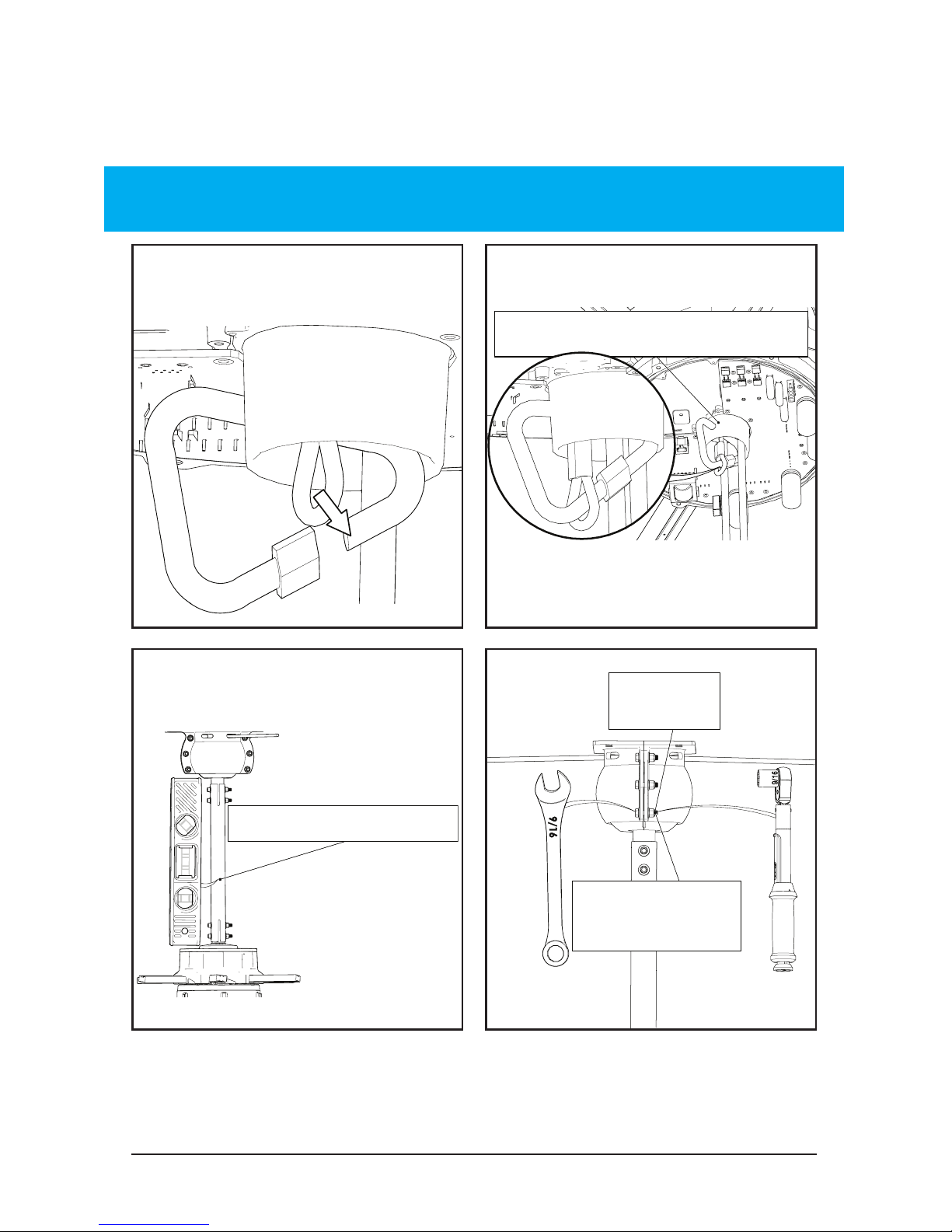
2.3 All Rapid Mounts Industrial
Motor Unit
Be careful of wires
30 ft-lbs
30 ft-lbs
[41 N-m]
Carefully guide the motor shaft into the extension tube.
CAUTION: Do not put force onto the building with the lift.
9/16”
Note: If purchased with the guy wire assembly, the guy wire brackets
must be installed at this stage. See page 25 for more details.
Page 42
© 2018 MacroAir Technologies Toll Free: 866 668 3247 Fax: 909 890 2 313 www.macroairfans.com 41
Rev. Date 040218
Ensure the fan is level
30 ft-lbs
Tighten only the
middle and bottom
bolts on both sides
30 ft-lbs
[41 N-m]
Tighten only the
middle and bottom
bolts on both sides
2.3 All Rapid Mounts Industrial
Motor Unit
Do not bend rubber bootDo not bend rubber boot
WARNING: Do not put too much tension on the safety cable. This will
deform the rubber boot and hinder the proper cooling of the motor.
Rapid Mount Industrial I-Beam safety cable starts on page 42
Rapid Mount Industrial Glulam safety cable starts on page 43
Rapid Mount Industrial Unistrut safety cable starts on page 44
9/16”
Page 43
© 2018 MacroAir Technologies Toll Free: 866 668 3247 Fax: 909 890 2 313 www.macroairfans.com 42
Rev. Date 040218
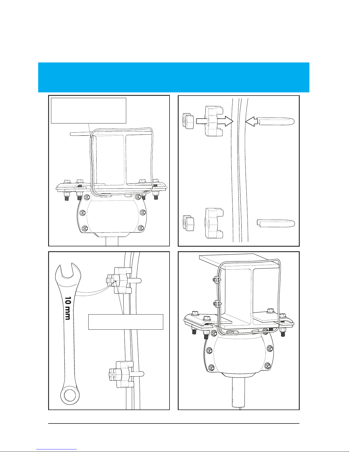
2.4.1 Rapid Mount Industrial
I-Beam Safety Cable
Tighten both nuts
Run safety cable
around I-Beam
WARNING: Do not put too much tension on the safety cable. There needs
to be a small amount of slack present in the safety cable for proper
functioning. Avoid sharp edges.
Complete safety cable installation and turn to page 45
Page 44
© 2018 MacroAir Technologies Toll Free: 866 668 3247 Fax: 909 890 2 313 www.macroairfans.com 43
Rev. Date 040218
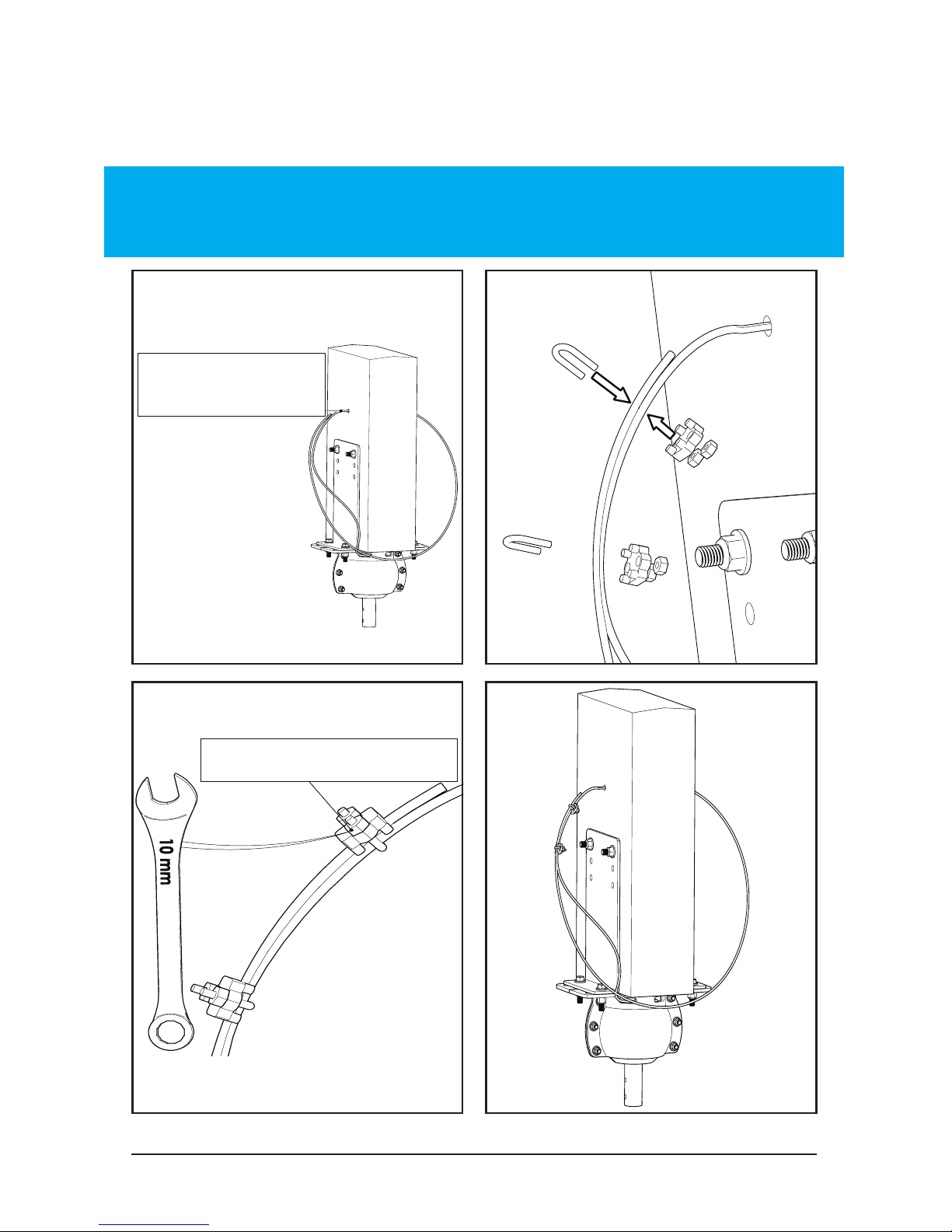
Tighten both nuts
Run safety cable
though hole
Run safety cable
though hole
2.4.2 Rapid Mount Industrial
Glulam Safety Cable
WARNING: Do not put too much tension on the safety cable. There
needs to be a small amount of slack present in the safety cable for
proper functioning. Avoid sharp edges.
Complete safety cable installation and turn to page 45
Page 45

© 2018 MacroAir Technologies Toll Free: 866 668 3247 Fax: 909 890 2 313 www.macroairfans.com 44
Rev. Date 040218
2.4.3 Rapid Mount Industrial
Unistrut Safety Cable
The safety cable must be securely attached to the building
structure and NOT the unistrut. It can be attached to I-beams,
steel trusses, or Glulams as shown in sections 2.4.1 and 2.4.2.
Avoid sharp edges. If you are unsure how to secure the safety
cable properly, contact a structural engineer.
Complete safety cable installation and turn to page 45
Page 46
© 2018 MacroAir Technologies Toll Free: 866 668 3247 Fax: 909 890 2 313 www.macroairfans.com 45
Rev. Date 040218
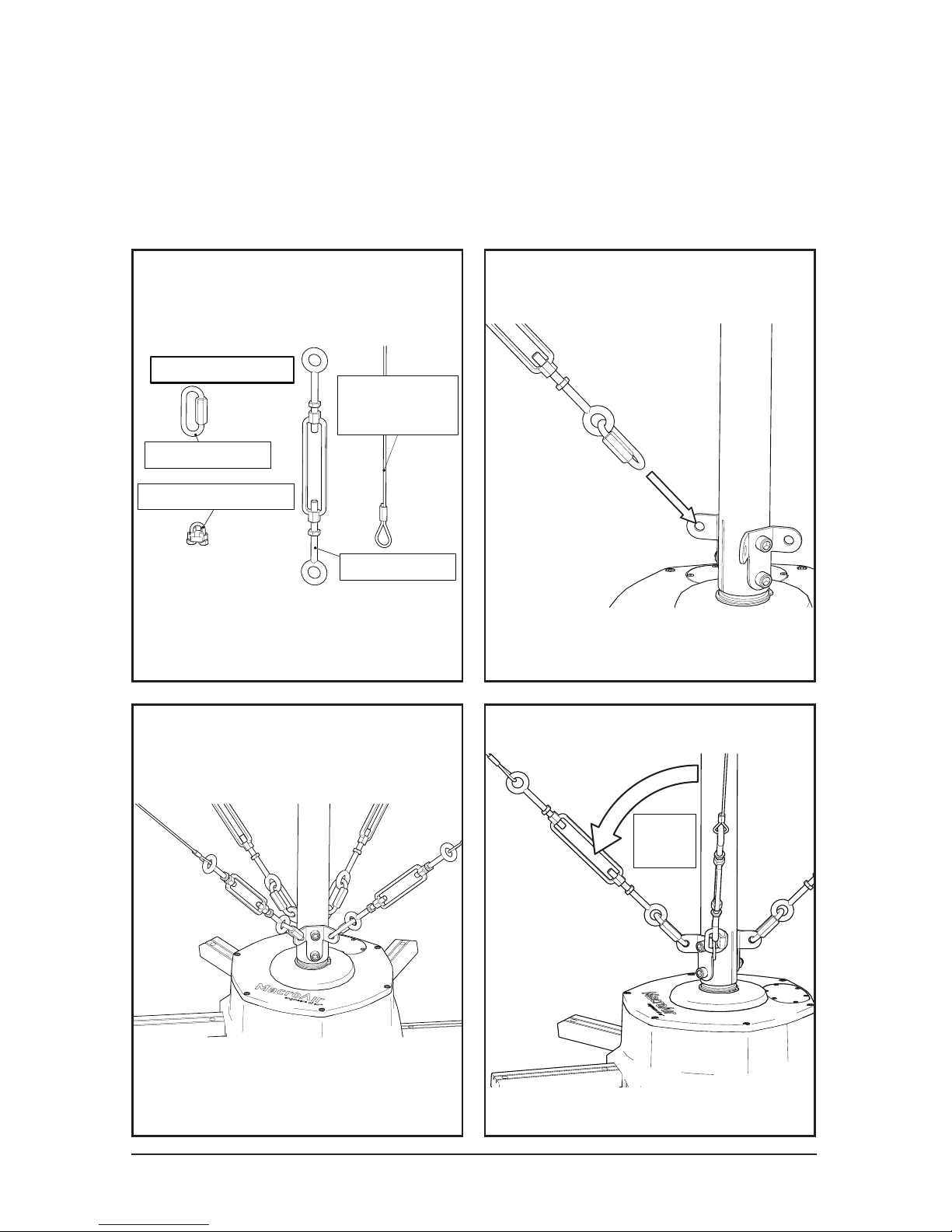
3. Guy Wire Installation
Guy Wire Assembly
Wire Rope (4)
19ft (A), 23ft (B),
or 33ft (C)
Turn Buckle (4)
1/4" Quicklink (4)
Wire Rope Clamp (8)
45°
Required for the Universal Mount.
Optional for the Rapid Mount Industrial. With the Rapid Mount
Industrial, use only when the building or environment conditions
require. Guy wire brackets must be installed to the base of the
Rapid Mount Extension Tube (see page 25).
Page 47
© 2018 MacroAir Technologies Toll Free: 866 668 3247 Fax: 909 890 2 313 www.macroairfans.com 46
Rev. Date 040218
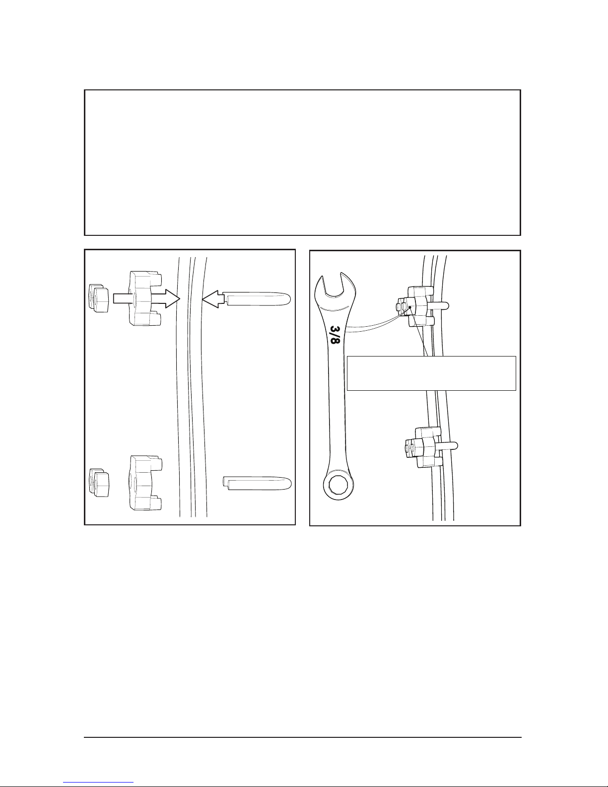
Note: Guy wires need to be securely mounted to
the building. You can use generic beam clamps
when mounting to I-Beam or steel truss. Lag
I-Bolts can be used when mounting to wood
Glulams. Do not wrap guy wires around the
building structure.
3. Guy Wire Installation
Tighten both nuts
Page 48
© 2018 MacroAir Technologies Toll Free: 866 668 3247 Fax: 909 890 2 313 www.macroairfans.com 47
Rev. Date 040218
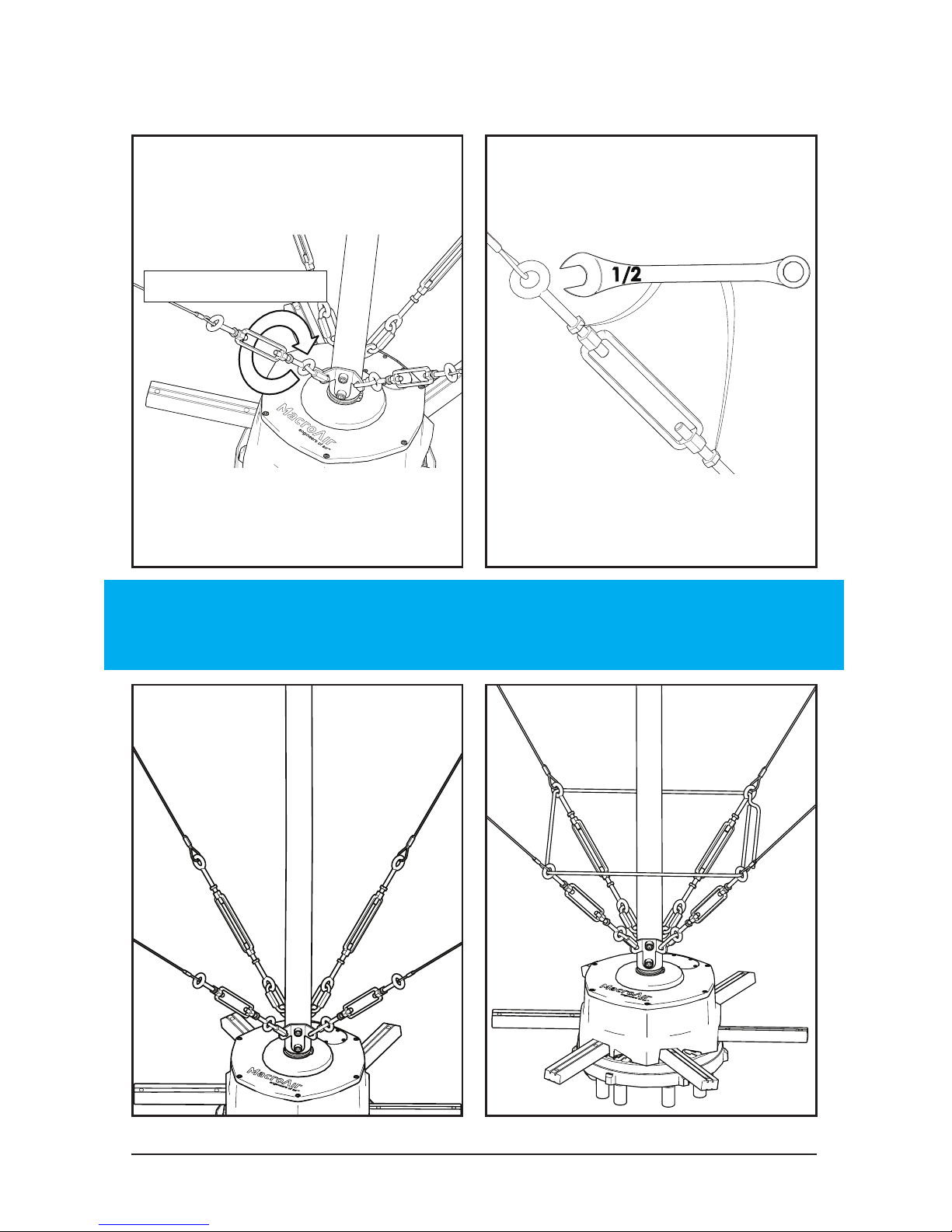
Hand Tighten ONLY
Tighten the jam nuts
Note: Make sure the
fan remains level
3. Guy Wire Installation
NOTE: Do not use tools to tighten the turnbuckles; only use tools to
tighten the jam nuts. The guy wires MUST be taut so that there is no
movement in the motor or extension tube.
Page 49
© 2018 MacroAir Technologies Toll Free: 866 668 3247 Fax: 909 890 2 313 www.macroairfans.com 48
Rev. Date 040218
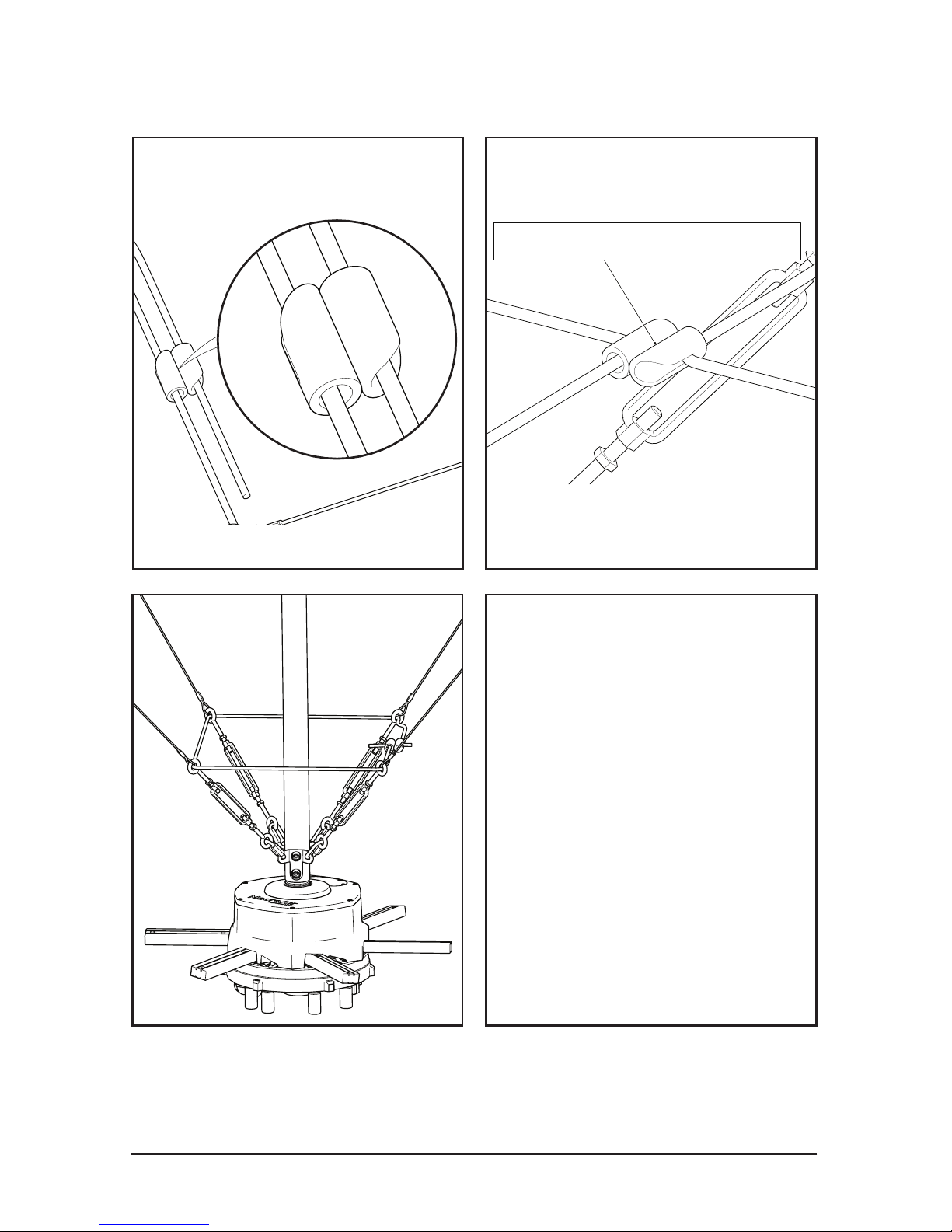
Bend Cord Through Clip
Note: The cord is cut to
a predetermined length
for proper tension. DO
NOT excessively stretch
the cord.
3. Guy Wire Installation
Page 50
© 2018 MacroAir Technologies Toll Free: 866 668 3247 Fax: 909 890 2 313 www.macroairfans.com 49
Rev. Date 040218
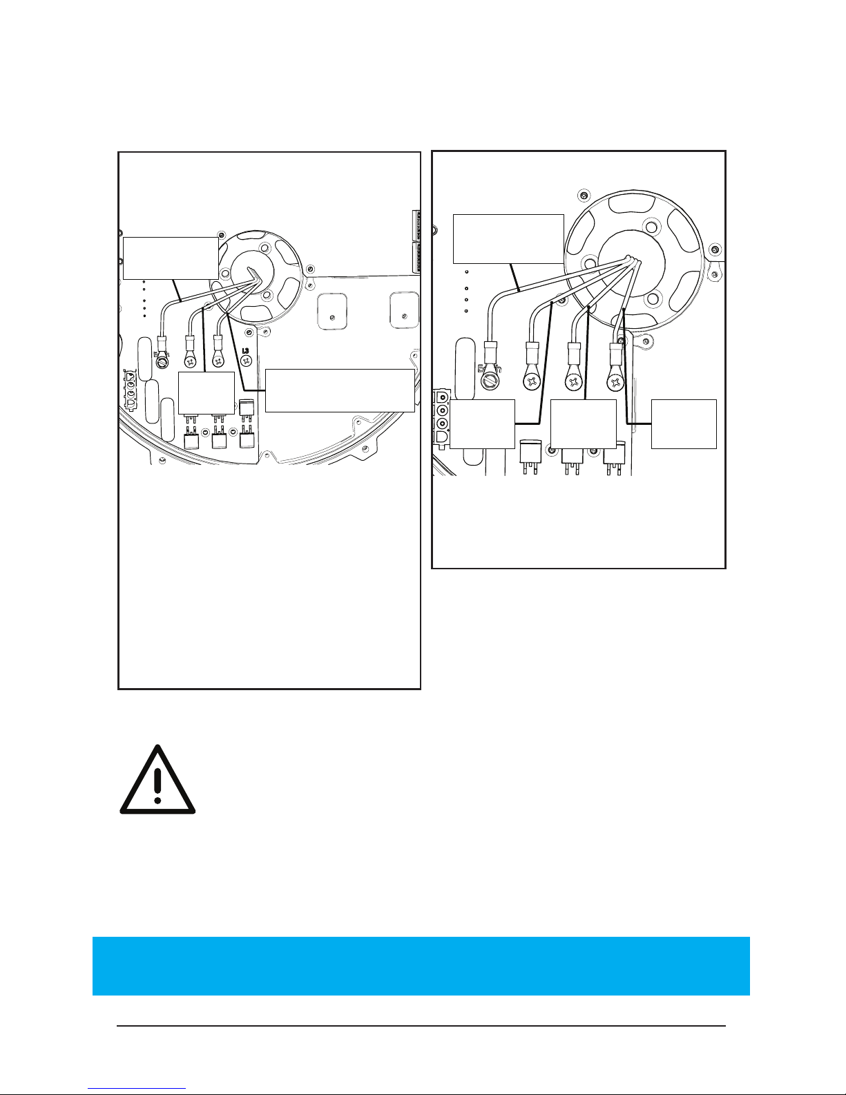
4.1 Drive Installation
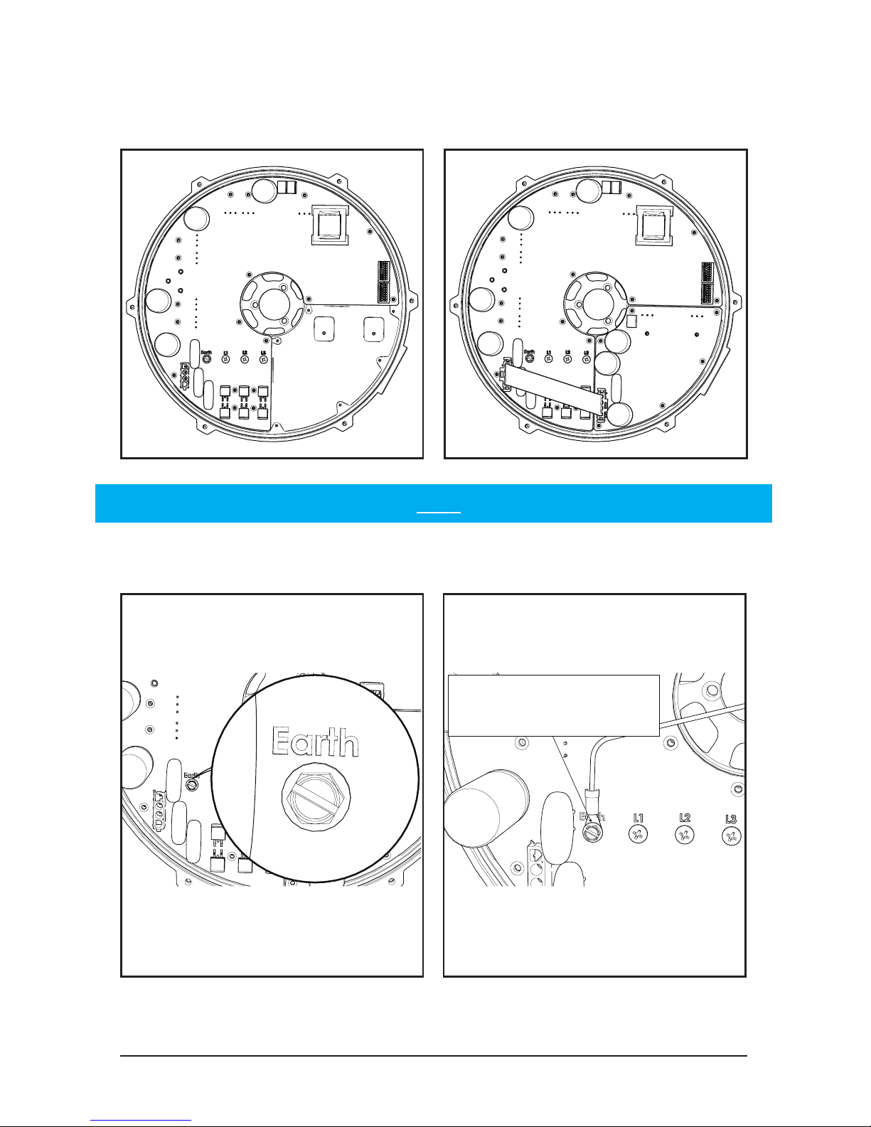
Ensure ground wire is
properly attached
CAUTION: RISK OF ELECTRIC SHOCK. The bus capacitors discharge
to a level below 50V DC in 1 minute.
Note: Model numbers ending with an “H” are high voltage while model
numbers ending with an “L” are low voltage.
High Voltage Drive
WARNING: POWER ABOVE 255VAC WILL DESTROY A LOW VOLTAGE DRIVE
Low Voltage Drive
Page 51
© 2018 MacroAir Technologies Toll Free: 866 668 3247 Fax: 909 890 2 313 www.macroairfans.com 50
Rev. Date 040218
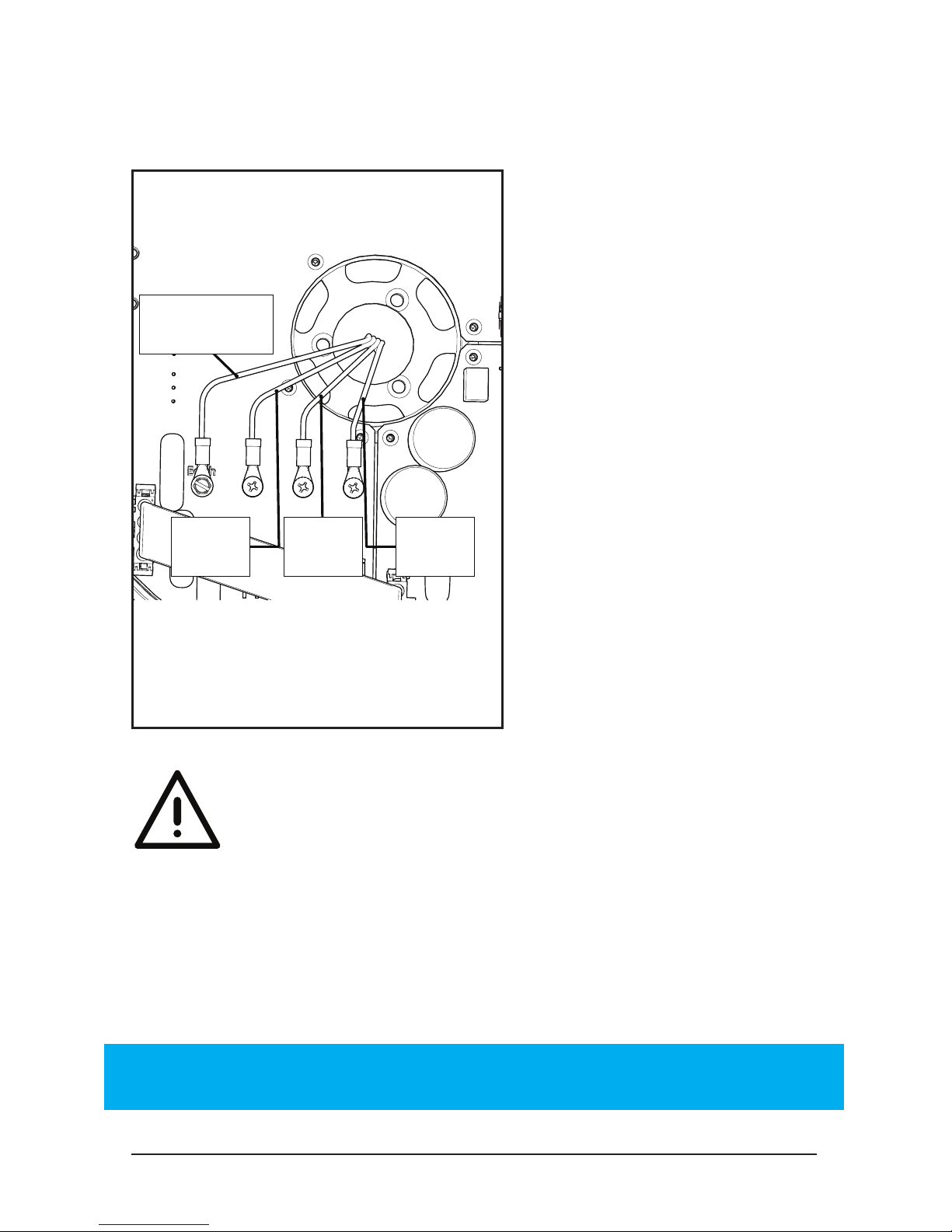
4.1.1 Drive Installation
Low Voltage
Ground
Neutral/Live
Live
LiveLiveLive
Ground
WARNING: DO NOT RUN FANS WITHOUT AIRFOILS. THE FANS ARE
NOT CONFIGURED TO OPERATE WITHOUT AIRFOILS ATTACHED.
WHEN CYCLING INCOMING POWER, WAIT ONE (1)
MINUTE BEFORE TURNING THE POWER BACK ON!
Single Phase Low
Voltage
Three Phase Low
Voltage
Model 550
Low Voltage:
120-240VAC
Model 780
Low Voltage:
208-240VAC
Models 550 & 780
Low Voltage:
208-240 VAC
WARNING: Keep hands away
from components.
CAUTION: RISK OF ELECTRIC
SHOCK. The bus capacitors
discharge to a level below 50V DC in
1 minute.
Note: Make sure the fan is run only when the cover is reinstalled.
The drive should only be operated in a pollution degree two (2)
environment, which is achieved with the bottom cover on.
Page 52
© 2018 MacroAir Technologies Toll Free: 866 668 3247 Fax: 909 890 2 313 www.macroairfans.com 51
Rev. Date 040218
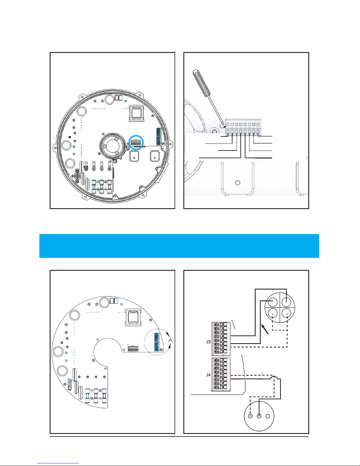
4.1.2 Drive Installation
High Voltage
Ground
Live
LiveLive
Three Phase High
Voltage
Models 550 & 780
High Voltage:
380-600 VAC
WARNING: Keep hands away
from components.
CAUTION: RISK OF ELECTRIC
SHOCK. The bus capacitors
discharge to a level below 50V
DC in 1 minute.
WARNING: DO NOT RUN FANS WITHOUT AIRFOILS. THE FANS ARE
NOT CONFIGURED TO OPERATE WITHOUT AIRFOILS ATTACHED.
WHEN CYCLING INCOMING POWER, WAIT ONE (1)
MINUTE BEFORE TURNING THE POWER BACK ON!
Note: Make sure the fan is run only when the cover is reinstalled.
The drive should only be operated in a pollution degree two (2)
environment, which is achieved with the bottom cover on.
Page 53
© 2018 MacroAir Technologies Toll Free: 866 668 3247 Fax: 909 890 2 313 www.macroairfans.com 52
Rev. Date 040218
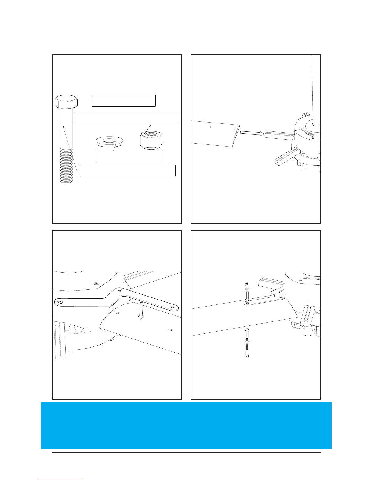
4.2 Control Wiring
Analog Control Wiring
Stranded Shielded
CAT5e only
NOTE: Fans must be ordered for analog control as they require
network conguration to enable analog terminals.
Digital Control Wiring
Use a at head screwdriver to press the small button on top of
the terminal block to securely attach the wires.
Orange
Orange/White
Brown/White
Green
Blue/White
Blue
Green/White
Brown
RTN
FOR/OFF/REV SWITCH
(VIEWED FROM BACK)
Forward
Reverse
Common
Speed
Detail A
SPEED POT
(VIEWED
FROM BACK)
Speed
IN 3
IN 4
RTN
Green
Blue
Blue/White
Green/White
IN 5
Brown
Page 54
© 2018 MacroAir Technologies Toll Free: 866 668 3247 Fax: 909 890 2 313 www.macroairfans.com 53
Rev. Date 040218
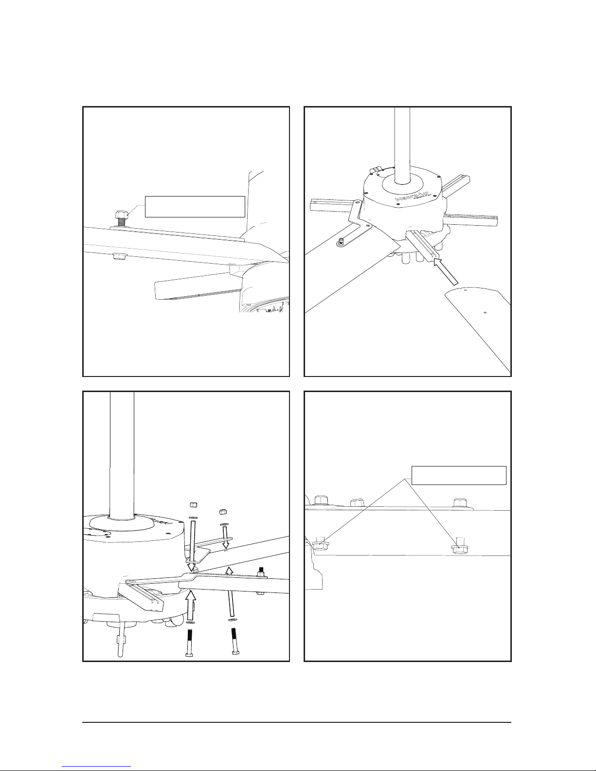
5. Airfoil Installation
5/16"-24 x 2" Hex Bolt (12)
5/16" Washer (24)
5/16"-24 Nylon Lock Nut (12)
6 Blade Bolt Kit
WARNING: To reduce the risk of personal injury, do not bend the
airfoils or airfoil struts when installing the airfoils, balancing the
airfoils, or cleaning the fan. Do not insert foreign objects in between
rotating fan airfoils.
Page 55
© 2018 MacroAir Technologies Toll Free: 866 668 3247 Fax: 909 890 2 313 www.macroairfans.com 54
Rev. Date 040218
5. Airfoil and Retainer Link
Installation
Hand Tighten
Hand Tighten
Repeat the last three steps until all six blades and retaining
links are in place.
Page 56
© 2018 MacroAir Technologies Toll Free: 866 668 3247 Fax: 909 890 2 313 www.macroairfans.com 55
Rev. Date 040218
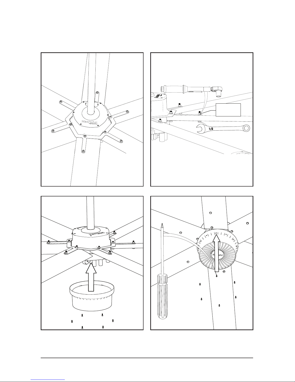
20 ft-lbs
20 ft-lbs
[27 N-m]
1/2
5. Retainer Link and Cover
Installation
Page 57
© 2018 MacroAir Technologies Toll Free: 866 668 3247 Fax: 909 890 2 313 www.macroairfans.com 56
Rev. Date 040218
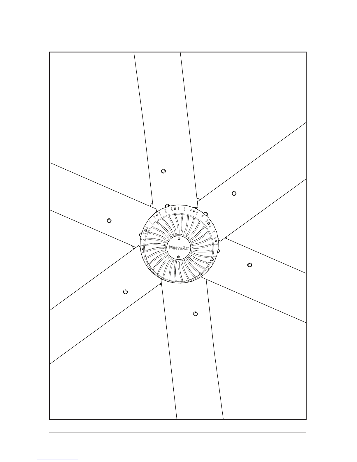
5. Airfoil Installation
Page 58
© 2018 MacroAir Technologies Toll Free: 866 668 3247 Fax: 909 890 2 313 www.macroairfans.com 57
Rev. Date 040218
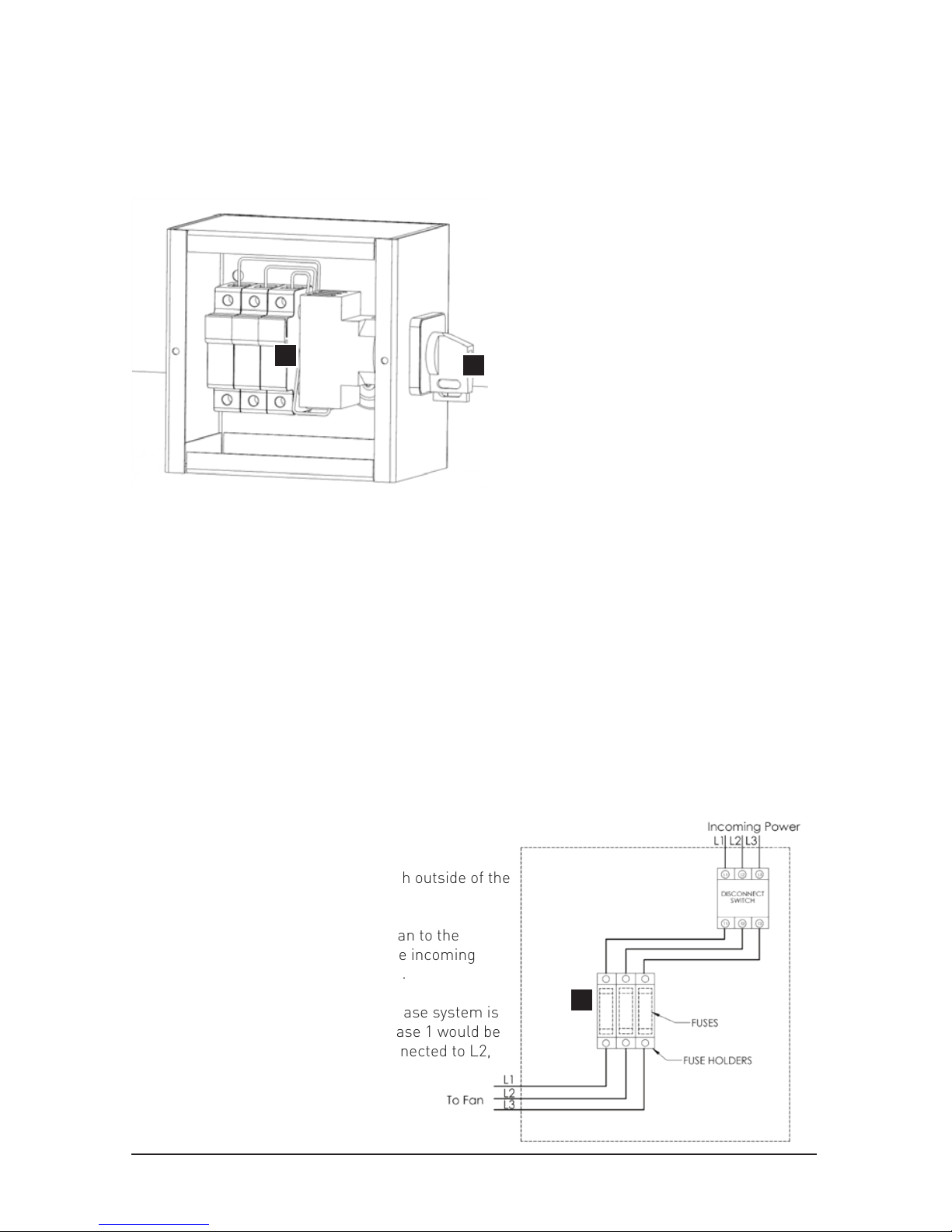
6.1 Fuse Disconnect Switch
Installation (Recommended but Optional)
A
B
The fuse disconnect switch is an optional component
offered by MacroAir. Reference page 5 for fuse
size based upon the incoming power and fan
diameter.
6.1.1: Mount the fuse disconnect switch outside of the
swept area of the fan airfoils.
6.1.2: Wire the power cable from the fan to the
bottom of the fuse block. Then wire the incoming
power source to the disconnect switch.
6.1.3: In the diagram below, a three phase system is
shown. For a single phase system, phase 1 would be
connected to L1, neutral would be connected to L2,
and L3 would be left not terminated.
C
Components:
A - Fuse Block (Optional Add-On)
B - Disconnect Switch (Optional Add-On)
C - Class gG Fast Acting Fuses (Not Provided) - refer to the fuse chart on page 5
NOTE: Ensure that there is no power when installing this component.
Means for disconnection with contact separation at least 3mm.
Service Disconnect (Required
per NEC, OSHA, IEC, CE and
UL compliance).
Not Included Optional Add-On
Page 59
© 2018 MacroAir Technologies Toll Free: 866 668 3247 Fax: 909 890 2 313 www.macroairfans.com 58
Rev. Date 040218
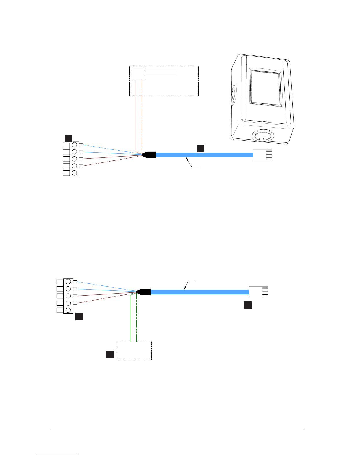
Components:
A - Remote Harness (found in single fan remote enclosure)
B - Terminal Block Connector
Use the schematic above to connect the fan(s) to an emergency stop (i.e. re
alarm system).
Remote Harness
TO FIRE ALARM (CONTROL CIRCUIT)
OPTIONAL
CUSTOMER - SUPPLIED
NORMALLY CLOSED RELAY
N.C.
RELAY
BLUE/WHITE
BLUE
BROWN
BROWN/WHITE
ORANGE
ORANGE/WHITE
A
B
6.2 Emergency Disconnect
Schematic
Remote Harness
BLUE/WHITE
BLUE
BROWN
BROWN/WHITE
GREEN
GREEN/WHITE
OPTIONAL
ON - OFF
SWITCH
6.3 Enable (ON)/Disable (OFF)
Schematic
A -Remote Harness (found in single fan remote enclosure)
B - Terminal Block Connector
C- Green/Green-White pair for remote on/off fan control
Use the schematic above to tie fan(s) to a remote set of supervisory contacts
for fan control. To enable this feature please contact MacroAir Technical
Support. Contact information can be found on page 74.
A
B
C
Fan remote enclosure →
Remote Harness
found inside fan
remote enclosure
Page 60
© 2018 MacroAir Technologies Toll Free: 866 668 3247 Fax: 909 890 2 313 www.macroairfans.com 59
Rev. Date 040218
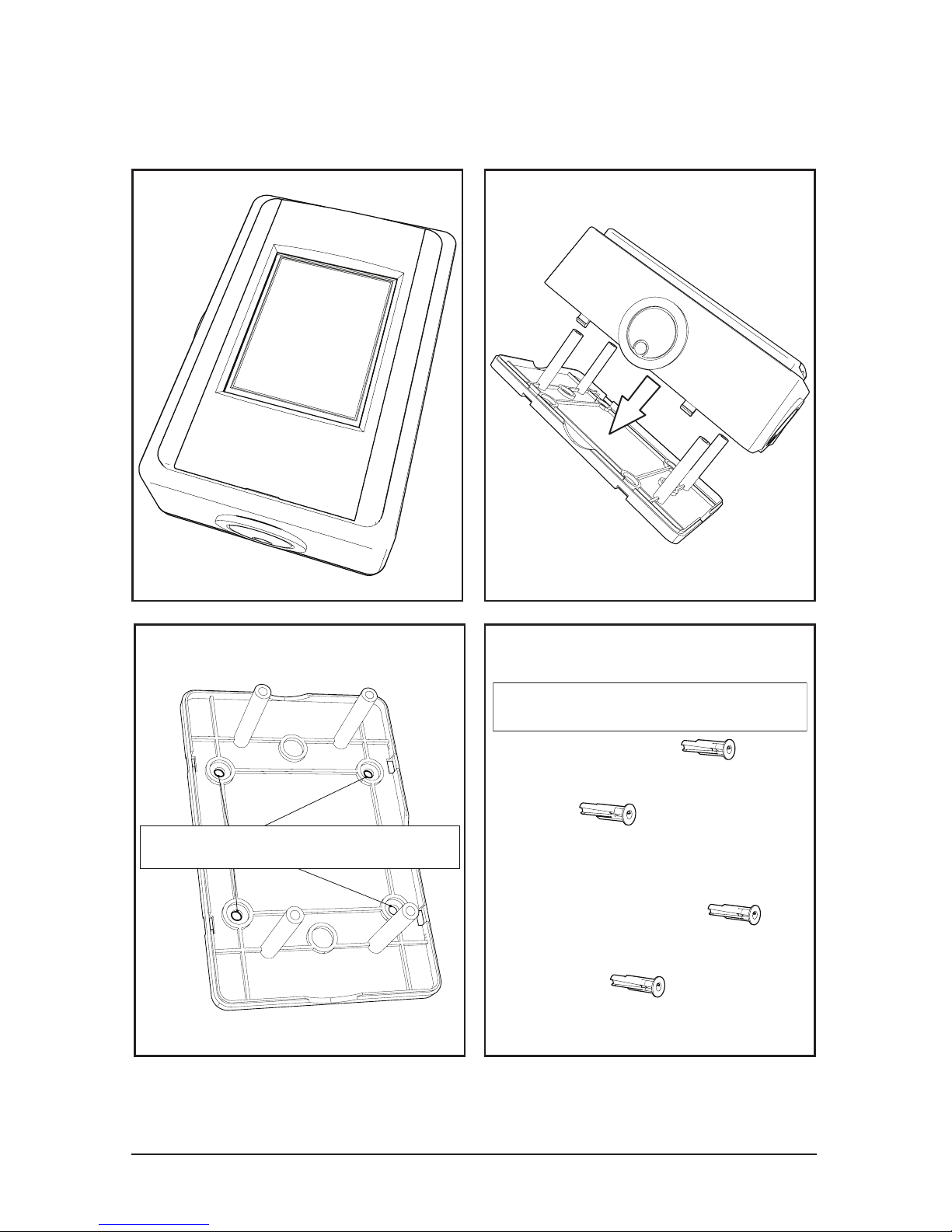
7.1 Touchpad Remote Mounting
Place anchors into wall
Flush Mounting is also available with a standard electrical
box (not provided).
Remove plastic punchouts
Page 61
© 2018 MacroAir Technologies Toll Free: 866 668 3247 Fax: 909 890 2 313 www.macroairfans.com 60
Rev. Date 040218
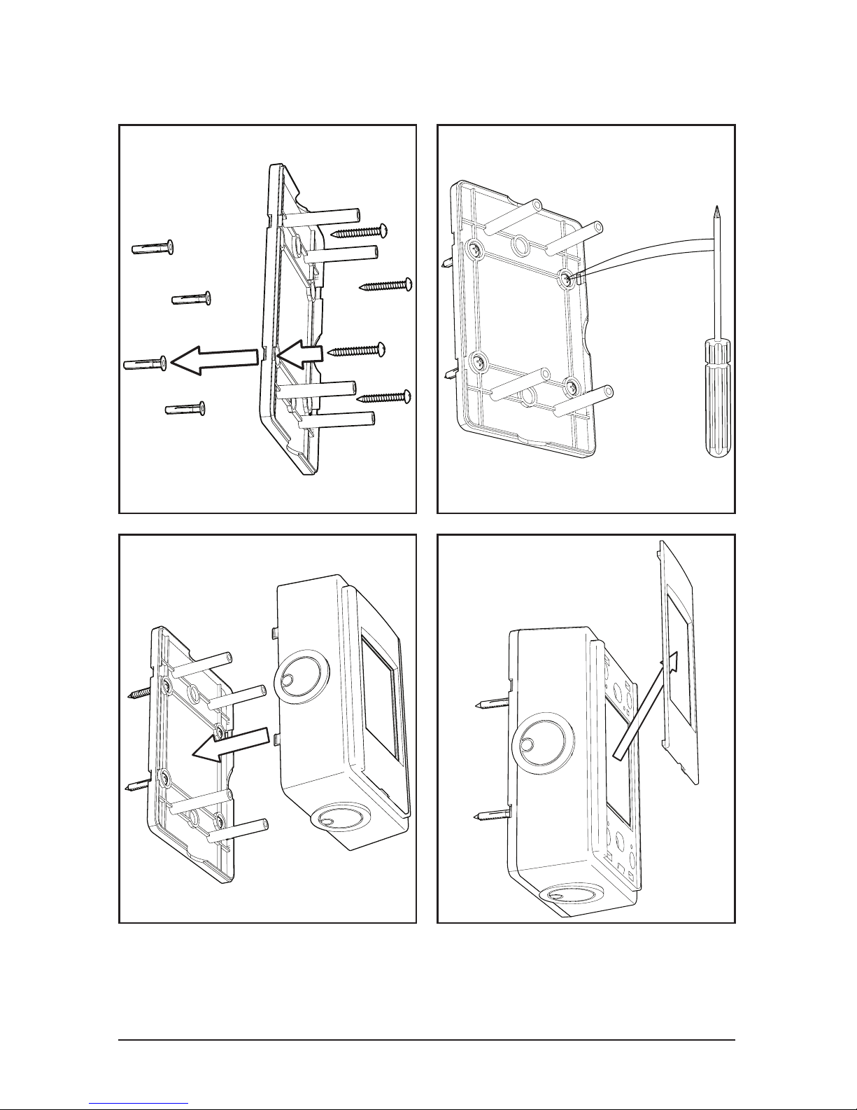
7.1 Touchpad Remote Mounting
Note: 100 feet of shielded stranded CAT5e cable is provided standard.
Up to 400 feet of cable can be ordered, and 400 feet is the maximum
distance allowed.
Page 62
© 2018 MacroAir Technologies Toll Free: 866 668 3247 Fax: 909 890 2 313 www.macroairfans.com 61
Rev. Date 040218
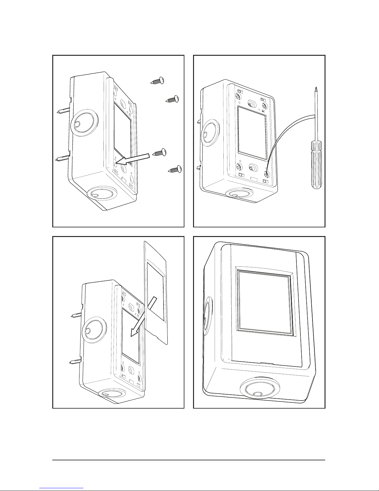
7.1 Touchpad Remote Mounting
The provided shielded stranded CAT5e cable from the fan is
plugged into the top of the enclosure.
Page 63

© 2018 MacroAir Technologies Toll Free: 866 668 3247 Fax: 909 890 2 313 www.macroairfans.com 62
Rev. Date 040218
7.2 Touchpad Remote Navigation
Buttons:
A - Forward / Reverse: Select fan rotational direction
B - Power Button: Turn the fan on or off (forward or reverse must be chosen to start the fan)
C - Speed Up / Speed Down: Increase or decrease the speed of the fan
D - Speed Box: Real-time indication of fan speed
E - Navigation: Navigate to the next screen
F - Settings: Displays settings and information about the fan
E
F
E
A
C
C
B
D
A
Page 64
© 2018 MacroAir Technologies Toll Free: 866 668 3247 Fax: 909 890 2 313 www.macroairfans.com 63
Rev. Date 040218
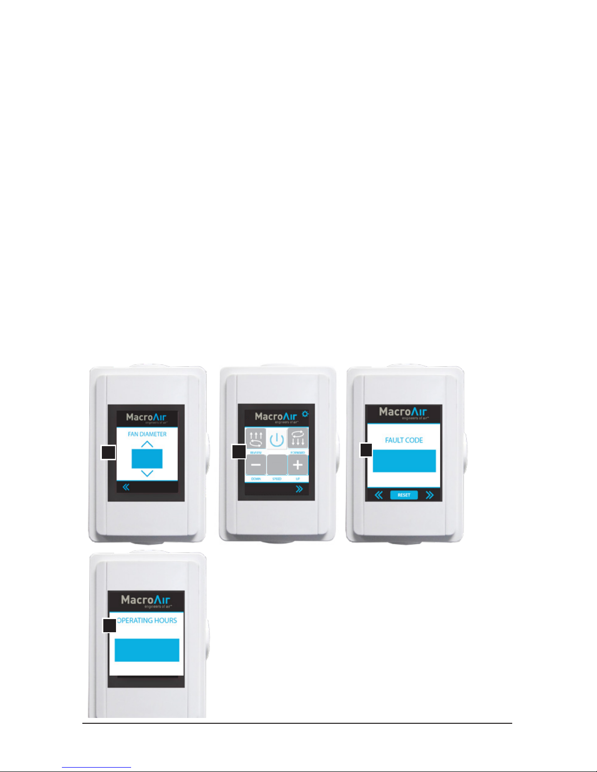
7.2 Touchpad Remote Operation
Screens:
A - Fan Diameter Selection Screen
B - Home Screen
C - Fault Code Screen
D - Operating Hours Screen
Instructions:
6.2.1: Upon initial power-up, the touchpad remote will default to the fan diameter auto detect
screen. You will need to select “6 blades” to initiate the auto detect. While the auto detect is
running you will not be able to leave the screen until the sequence is nished. Once the startup
sequence is completed you will be able to leave the screen by hitting the left arrows in the footer
to navigate to the home screen.
6.2.2: Once on the home screen, test your fan by setting the speed to 100 in forward operation by
increasing the speed and then clicking the forward button. Keep the fan’s speed at 100 for a few
minutes to ensure proper functionality.
6.2.3: If the fan stops operating unexpectedly, navigate to the fault code screen and record any
fault codes (if present). Click the reset button until the display reads ‘0’ or none. Then, attempt
to run the fan again. If the fan is still not operating, navigate to the fault code screen via the
navigation arrows at the bottom of the screen and document the code(s) displayed and call
technical support at 866-668-3247.
6.2.4: To view your fan’s operating hours, navigate from the home screen to the far right screen.
C
D
A
E
B
Page 65

© 2018 MacroAir Technologies Toll Free: 866 668 3247 Fax: 909 890 2 313 www.macroairfans.com 64
Rev. Date 040218
Maintenance Information
Guy Wire Check (if applicable): Checking a MacroAir fan’s guy wires for tension and inspecting
for frayed sections could mitigate a problem before it occurs. The guy wires should be under
enough tension to prevent any movement in the motor unit or the extension tube. If the motor
can be moved by pushing on it, the guy wires need to be tightened. Fan owners should conrm
that the guy wires are not wrapped around any sharp edges. MacroAir recommends attaching
guy wires to the building with eye bolts or eye lags. If they are not already installed with eye bolts
or lags, we urge fan owners to install these in order to help keep the guy wires from fraying.
If guy wires are installed with turnbuckles, jam nuts should periodically be checked to ensure
tightness. If they are loose, the guy wire cables may need to be re-tensioned.
Airfoil Cleaning: Depending on the type of commercial application the MacroAir fan is in, there
can be quite a bit of dust or other particulates that cling to the fan’s airfoils. While this may not
affect fan performance, we recommend fan owners keep airfoils clean by having a maintenance
person or skilled trade professional – who has experience using a lift – wipe the fan airfoils with
a rag or sponge using hot water or regular cleaning solutions. Please do not use chlorine or any
chemicals containing chlorine.
Safety Cable Check: Each MacroAir fan comes with a safety cable. Depending on the fan model,
the safety cable either wraps around the building structure and the fan frame, or comes out
of the top of the fan and wraps around the building structure. The safety cable is an important
part of the safety system and acts as a last resort should an earthquake, collision, or similar
catastrophic event occur. As such, it’s vital for fan owners to ensure that it is intact and properly
secured.
Reverse Operation: The beauty of MacroAir HVLS fans is that they are built to run in forward and
reverse mode. However, changing the direction of your fan can put initial stress on the fan if it
has not been properly checked. It is a good idea to make sure guy wires, safety cables and all
bolts and nuts are tight. Cleaning the fan before switching directions will prevent dust and other
particles from falling off the fan airfoils when turning in the opposite direction.
Maintenance Plan:
Things to look for include: properly torqued fasteners, rust, cracked welds, unusual noise, hub
migration/movement, guy wire loosening or movement.
Year 1-10:
One inspection on lift per year.
Year 11 and beyond:
Annual inspections from a lift and seasonal inspections both before and after the busy season
from the ground.
NOTE: If there are issues or concern discovered during an inspection, please contact the service
and technical support department at MacroAir for help.
Page 66
© 2018 MacroAir Technologies Toll Free: 866 668 3247 Fax: 909 890 2 313 www.macroairfans.com 65
Rev. Date 040218
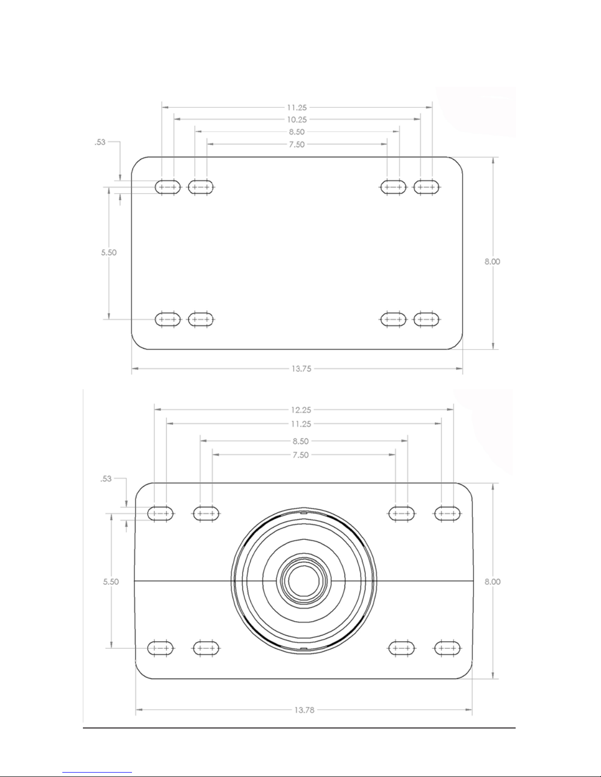
Mounting Plate Dimensions
Universal Mount
Rapid Mount
Page 67
© 2018 MacroAir Technologies Toll Free: 866 668 3247 Fax: 909 890 2 313 www.macroairfans.com 66
Rev. Date 040218
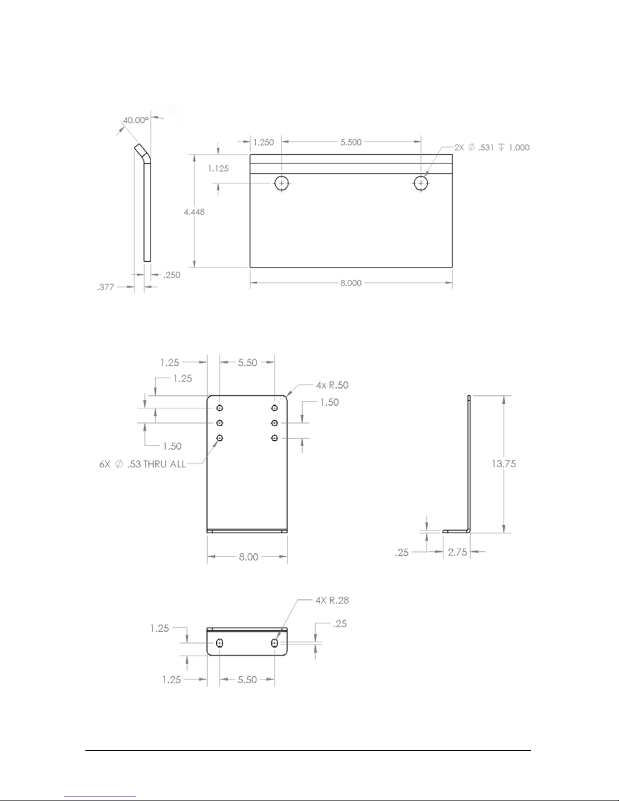
Mounting Bracket Dimensions
I-Beam Bracket
Glulam Bracket
Page 68
© 2018 MacroAir Technologies Toll Free: 866 668 3247 Fax: 909 890 2 313 www.macroairfans.com 67
Rev. Date 040218
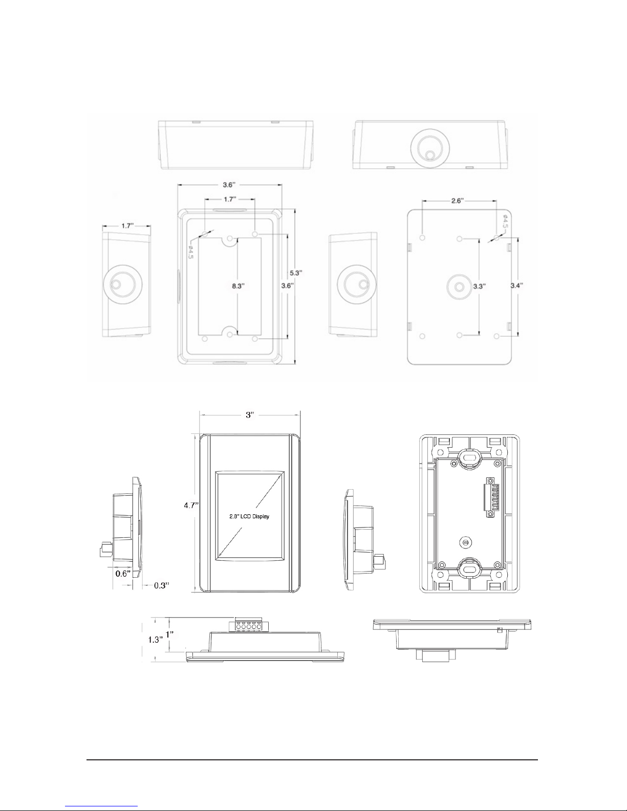
Touchpad Remote Dimensions
Remote Enclosure
Remote LCD Display
Page 69
© 2018 MacroAir Technologies Toll Free: 866 668 3247 Fax: 909 890 2 313 www.macroairfans.com 68
Rev. Date 040218
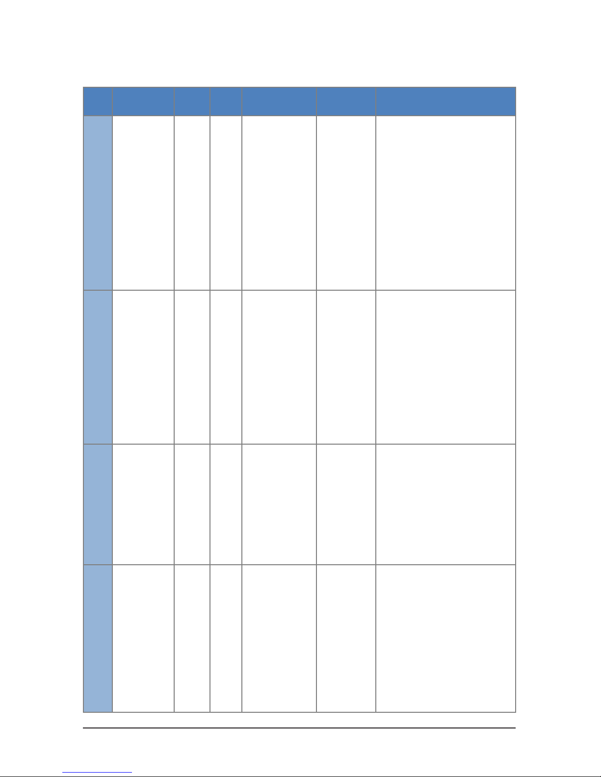
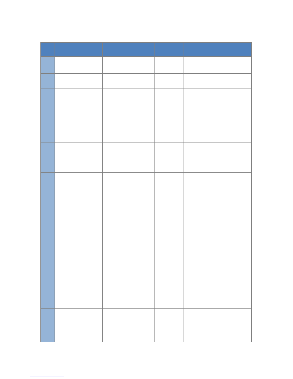
Troubleshooting
It is recommended to wire the fan and the touchpad remote prior to turning on the power to the
fan. If the fan is not operable, but the touchpad remote is lighting up, cycle power to the fan.
If cycling the power did not resolve this issue, go to the fault code screen (reference page 63) and
check to see if there is a code present.
Fault Code Causes and Possible Solutions
Code Name
Code
Type
Factory
Setting
Description Symptoms Troubleshooting Tips
1000
Supply Voltage
High Warning
Warning 425V DC
The controller
monitors the bus
voltage to verify it’s
below the threshold
Fan Slows
Intermittent/
No Operation
1. Turn incoming power off for two
minutes, turn back on
2. Conrm power is within fan’s
specications
3. Check for spikes with power quality
recorder
4. Conrm that motor wiring is correct
(A is white, B is black and C is red)
1001
Supply Voltage
Low Warning
Warning 80V DC
The controller
monitors the bus
voltage to verify it’s
above the threshold
Fan Slow
Intermittent/
No Operation
1. Turn incoming power off for two
minutes, turn back on
2. Conrm incoming power is within
fan’s specications
3. Ask if power has gone out recently or
if there have been storms in the area
4. Conrm that motor wiring is correct
(A is white, B is black and C is red)
1002
Supply Voltage
High Fault
AutoReset
450V DC
The controller
monitors the bus
voltage to verify it’s
below the threshold
and will disable the
fan if it is exceeded
Intermittent/
No Operation
1. Turn incoming power off for two
minutes, turn back on
2. Conrm power is within fan’s
specications
3. Check for spikes with power quality
recorder
4. Conrm that motor wiring is correct
(A is white, B is black and C is red)
1003
Supply Voltage
Low Fault
Halt 40V DC
The controller
monitors the bus
voltage to verify it’s
above the threshold
and will disable the
fan if it is exceeded
Intermittent/
No Operation
1. Turn incoming power off for two
minutes, turn back on
2. Conrm power is within fan’s
specications
3. Ask if power has gone out recently or
if there have been storms in the area
4. Conrm that motor wiring is correct
(A is white, B is black and C is red)
Page 70
© 2018 MacroAir Technologies Toll Free: 866 668 3247 Fax: 909 890 2 313 www.macroairfans.com 69
Rev. Date 040218
Code Name
Code
Type
Factory
Setting
Description Symptoms Troubleshooting Tips
1004
Phase Current A
High Fault
AutoReset
Intermittent/
No Operation
Vibration or
Grinding Noises
1. Turn incoming power off for two
minutes, turn back on
2. Conrm power is within fan’s
specications
3. Perform a drive calibration
4. Conrm motor values, perform motor
calibration if possible/necessary
1005
Phase Current B
High Fault
AutoReset
1006
Phase Current C
High Fault
AutoReset
1007
Motor
Temperature
High Warning
Warning 100C
The controller
multiplies the
current torque
command by 0.5
when the motor
reaches 100C. There
is no hysteresis
on this value. It
goes back to full
speed when the
temperature falls
below the warning
value.
Fan Slowing/
Stopping
Intermittently
1. Conrm that motor temperature is
below 100C
2. Conrm that end caps are open and
there is no blockage in the blades
3. Conrm that the quick link on the
safety cable is not pulling the rubber
boot closed
4. Conrm that the ambient temperature
is below 60C
5. Start the fan earlier in the day before
the ambient temperature rises
1008
Motor
Temperature
High Fault
AutoReset
110C
Fan Stopping
Intermittently
1. Conrm that motor temperature is
below 110C
2. Conrm that end caps are open and
there is no blockage in the blades
3. Conrm that the quick link on the
safety cable is not pulling the rubber
boot closed
4. Conrm that the ambient temperature
is below 60C
5. Start the fan earlier in the day before
the ambient temperature rises
1009
Heatsink
Temperature
High Warning
Warning 75C
The controller
multiplies the
current torque
command by 0.5
when the heatsink
reaches 75C. There
is no hysteresis
on this value. It
goes back to full
speed when the
temperature falls
below the warning
value.
Fan Slowing/
Stopping
Intermittently
1. Conrm that heatsink temperature Is
below 75C
2. Conrm that end caps are open and
there is no blockage in the blades
3. Conrm that the quick link on the
safety cable is not pulling the rubber
boot closed
4. Conrm that the ambient temperature
is below 60C
5. Start the fan earlier in the day before
the ambient temperature rises
Troubleshooting
Page 71
© 2018 MacroAir Technologies Toll Free: 866 668 3247 Fax: 909 890 2 313 www.macroairfans.com 70
Rev. Date 040218
Code Name
Code
Type
Factory
Setting
Description Symptoms Troubleshooting Tips
1010
Heatsink
Temperature
High Fault
AutoReset
85C
Fan Stopping
Intermittently
1. Conrm that heatsink temperature Is
below 85C
2. Conrm that end caps are open and
there is no blockage in the blades
3. Conrm that the quick link on the
safety cable is not pulling the rubber
boot closed
4. Conrm that the ambient temperature
is below 60C
5. Start the fan earlier in the day before
the ambient temperature rises
1011
PCB
Temperature
High Warning
Warning 75C
Fan Slowing/
Stopping
Intermittently
1. Conrm that PCB temperature Is
below 75C
2. Conrm that end caps are open and
there is no blockage in the blades
3. Conrm that the quick link on the
safety cable is not pulling the rubber
boot closed
4. Conrm that the ambient temperature
is below 60C
5. Start the fan earlier in the day before
the ambient temperature rises
1012
PCB
Temperature
High Fault
AutoReset
80C
Fan Stopping
Intermittently
1. Conrm that PCB temperature Is
below 80C
2. Conrm that end caps are open and
there is no blockage in the blades
3. Conrm that the quick link on the
safety cable is not pulling the rubber
boot closed
4. Conrm that the ambient temperature
is below 60C
5. Start the fan earlier in the day before
the ambient temperature rises
1013
Phase Current
Following Error
AutoReset
Fan Stopping
Intermittently
Fan Not Starting
Fan “Twitching”
Fan Not Able
To Run Above
A Certain
Percentage
Fan Running
Slowly/
Irregularly
Grinding/
”Groaning”
Sounds
1. Ensure that blade length is properly
set
2. Perform a drive calibration
3. Conrm incoming power is within
fan’s specications
4. Conrm motor values. Perform power
calibration if possible/necessary
5. If fan shuts off above 95%, set ne
tuning to 5. If it shuts off above 90%, use
a ne tuning of 10
Troubleshooting
Page 72
© 2018 MacroAir Technologies Toll Free: 866 668 3247 Fax: 909 890 2 313 www.macroairfans.com 71
Rev. Date 040218
Code Name
Code
Type
Factory
Setting
Description Symptoms Troubleshooting Tips
1014
Sudden Change
Of Speed
AutoReset
20%
10 rpm
0.1 sec.
The controller looks
for a % change in
speed bounded by
a minimum RPM
change in a certain
amount of time. If
both conditions are
met, then the drive
will disable.
Fan Speeds Up
Suddenly
Fan “Twitches”
Fan Will Not
Run
Fan Stops
Suddenly
1. Ensure that blade length is properly
set
2. Perform a drive calibration
3. Conrm incoming power is within
fan’s specications
4. Conrm motor values. Perform power
calibration if possible/necessary
1015
Tilt Limit
Exceeded
AutoReset
+/- 5 °
Fan Wobbles
Fan Stops
Running
Fan Will Not
Start
1. Conrm that the tilt is below 5
degrees
2. Conrm that fan or structure is not
wobbling
3. Conrm that locking hardware on
mount is tight
4. Add guy wires if necessary
5. Disable tilt if guy wires are installed
1016
Vibration Limit
Exceeded
AutoReset
Fan Vibrates
Fan Wobbles
Fan “Twitches”
1. Conrm that fan or structure is not
wobbling
2. Conrm that locking hardware on
mount is tight
3. Add guy wires if necessary
1017
Keep-Alive
Timeout
AutoReset
10s
Fan Randomly
Stops
Fan Will Not
Start
1. Conrm whether touchpad was
unplugged or not
2. Conrm that CAT5 is under 100ft
3. Conrm that CAT5 is from factory and
has not been modied
4. Conrm that CAT5 is shielded
5. Conrm that repeaters are properly
installed on the network
6. Double check network splices
7. Plug touchpad directly into board
Troubleshooting
Page 73
© 2018 MacroAir Technologies Toll Free: 866 668 3247 Fax: 909 890 2 313 www.macroairfans.com 72
Rev. Date 040218
Troubleshooting
Code Name
Code
Type
Factory
Setting
Description Symptoms Troubleshooting Tips
1018 Fire Disconnect
AutoReset
Fan Stops
Fan Will Not
Start
1. Conrm whether touchpad was
unplugged or not
2. A 1018 is most commonly seen if the
touchpad is unplugged. In this case,
pressing the reset button should clear
the code and allow the fan to operate
normally.
3. Conrm that orange pair is twisted
together inside the screen enclosure
4. Conrm that the orange pair is being
ran throughout the whole CAT5 line
5. Plug touchpad directly into the fan to
see if the fault will clear
1019
Overspeed Fault
(Blades Too
Short)
AutoReset
-
Fan “Twitching”
Fan Will Not
Start
Fan Stops
Fan Faults Only
At High Speed
Fan Runs
Irregularly
1. Ensure that blade length is properly
set
2. Ensure that blades are installed
3. Perform a drive calibration
4. Conrm incoming power is within
fan’s specications
5. Conrm motor values, perform motor
calibration if possible/necessary
6. Perform ne tuning
1020
Underspeed
Fault (Blades
Too Long)
AutoReset
-
Fan “Twitching”
Fan Will Not
Start
Fan Stops
Fan Faults Only
At High Speed
Fan Runs
Irregularly
1. Ensure that blade length is properly
set
2. Ensure that blades are installed
3. Perform a drive calibration
4. Conrm incoming power is within
fan’s specications
5. Conrm motor values, perform motor
calibration if possible/necessary
1021
Communication
Buffer Full
Warning
Warning
Communication
Issues
1. Conrm that CAT5 is under 100ft
2. Conrm that CAT5 is from factory and
has not been modied
3. Conrm that CAT5 is shielded
4. Conrm that repeaters are properly
installed on the network
5. Double check network splices
6. Plug touchpad directly into board
7. Conrm Baud rate
Page 74
© 2018 MacroAir Technologies Toll Free: 866 668 3247 Fax: 909 890 2 313 www.macroairfans.com 73
Rev. Date 040218
Troubleshooting
Code Name
Code
Type
Factory
Setting
Description Symptoms Troubleshooting Tips
1022
Accelerometer
Read Fault
AutoReset
Fan Will Not
Run
Turn incoming power off for two
minutes, turn back on
1024
Blade Diameter
Not Set
AutoReset
Fan Will Not
Run
Program the fan’s diameter
1025
Blade Detect
Failed
AutoReset
Fan Will Not
Run
Fan Makes
Noises
1. Ensure that blades are installed
2. Manually set the blade length
3. Perform a drive calibration
4. Conrm incoming power is within
fan’s specications
5. Conrm motor values, perform motor
calibration if possible/necessary
1026
Local Disable
Active
AutoReset
The enable/disable
feature is active and
the green pair in the
CAT5 is open.
Verify that your enable/disable switch is
in the correct position. Verify that green
and green/white wires are installed
properly in switch.
1029
Drive Calibration
Error
Fault
A power calibration
was attempted while
the fan is active.
This is typically done
by pressing the
“Calibrate Drive”
button behind the
MKey.
Reset the drive
COMM
ERROR
Fan Stops
Fan Will Not
Start
1. Conrm whether touchpad was
unplugged or not
2. Conrm that CAT5 is under 100ft
3. Conrm that CAT5 is from factory and
has not been modied
4. Conrm that CAT5 is shielded
5. Conrm that repeaters are properly
installed on the network
6. Double check network splices
7. Plug touchpad directly into board
8. Test for 5VDC on blue pair if screen
lights up, test for 24VDC if screen does
not light up
N/A
Fan Takes a long
time to start /
does not start
Back and forth
oscillation at
start-up greater
then 15 seconds
1. Verify the correct blade setting is
selected
2. Verify motor parameters
3. Perform Power calibration
For all other fault codes, please call Technical Support at (866) 668-3247.
Page 75

© 2018 MacroAir Technologies Toll Free: 866 668 3247 Fax: 909 890 2 313 www.macroairfans.com 74
Rev. Date 040218
Warranty and Technical Support
To register the installed fans for the 50,000 hour
warranty, go to macroairfans.com/register.
What does the 50,000 hour warranty cover?
This warranty covers any part or component of the AirVolution-D shipped by MacroAir that is
found to contain a manufacturing defect. MacroAir will repair or replace such part, component,
or the entire fan free of charge.
How Long Does the Coverage Last?
This warranty covers the entire AirVolution-D fan and all its component parts for 50,000 hours of
running time.
Do I Need to Pay Shipping, Removal and Re-Installation Costs?
You do NOT need to pay shipping, removal and installation costs if your AirVolution-D needs to be
repaired or replaced due to a manufacturing defect within one year of the original purchase, and
you will be reimbursed for those costs, upon approval of such costs by MacroAir. After one year,
this warranty is still in full effect for the remainder of the 50,000 hours, but it does not cover your
cost to ship the fan to MacroAir, or removal or re-installation of the fan.
What is NOT covered under this warranty?
This warranty will not cover repairs or replacements caused by installation, operation or storage
of the fan that is outside the specications and limitations contained in the AirVolution-D
installation and operation instructions.
Technical Support
For installation assistance, application questions, technical sales support and any other inquiries,
please contact MacroAir at (866) 668-3247.
Page 76
© 2018 MacroAir Technologies Toll Free: 866 668 3247 Fax: 909 890 2 313 www.macroairfans.com 75
Rev. Date 040218
 Loading...