

Page 1
MAC PARA TECHNOLOGY LTD.
1. máje 823
756 61 Rožnov pod Radhoštěm
Czech Republic
Tel.: +420 571 842 235
Tel./fax: +420 571 842 332
e-mail: [email protected]
www.macpara.com
USER MANUAL
SPICESPICE
Page 2
Contents
General ..................................................................................................................... 2
Introduction ............................................................................................................ 2
Operating limits ...................................................................................................... 3
Construction ........................................................................................................... 4
Trim ........................................................................................................................ 4
Safety equipment ................................................................................................... 4
Speed System ....................................................................................................... 5
Flying operations ................................................................................................... 6
Checklist ................................................................................................................ 6
Take-off .................................................................................................................. 6
Flight ...................................................................................................................... 7
Steering ................................................................................................................. 7
Approach and landing ............................................................................................ 7
Flight with speed system ....................................................................................... 8
Towed flight and motorized flight ........................................................................... 8
Extreme and critical flight manoeuvres ............................................................... 8
Collapse of the canopy .......................................................................................... 9
- Asymmetrical collapse ...................................................................................... 9
- Symmetrical collapse ........................................................................................ 10
- Frontal deflation ................................................................................................ 10
Stalls ...................................................................................................................... 11
- Parachutal stall steering lines ........................................................................... 11
- B-line stall ......................................................................................................... 11
- Spin (Negative spiral) ....................................................................................... 12
- Full stall ............................................................................................................. 12
Spiral drive ............................................................................................................. 13
Descent rates ......................................................................................................... 14
Maintenance and repairs ....................................................................................... 14
Material description ............................................................................................... 15
Ground plan ............................................................................................................. 16
Line plan AC ............................................................................................................. 17
Line plan BD ............................................................................................................. 18
Manual for Paraglider checks ............................................................................... 19
Components of the check ...................................................................................... 19
Checks ..................................................................................................................... 21
Test flight certificate / Technicla data .................................................................. 22
2
GENERAL
Introduction
MAC Para Technology ltd wish you many pleasant flights with your
SPICE
We congratulate you on your purchase of a MAC-paraglider.
Extensive development work and numerous tests make the SPICE a high performance
paraglider with maximum possible safety.
The SPICE is constructed for powered flight, and will enable pilots to get maximum
enjoyment.
Please read this manual carefully before you start, this way you will get the most out of
your glider, and enjoy many nice flights.
Paramotoring is a sport, which demands, besides the optimum equipment, a high
degree of attentiveness, good judgement, and theoretical knowledge. Paramotoring can
be a dangerous sport, which may lead to injury and death. Avoid flying in strong
turbulence, strong winds and especially in thunderstorms and Foehn conditions. These
could lead to uncontrollable flight conditions and result in a crash. If you have the
slightest doubt about weather, wind or terrain, don’t take off.
Before delivery, as well as during production, each glider goes through a strict visual
inspection, and is test-flown by your dealer. Stamps on the placard, together with a
completed test-flight certificate, confirm this. Check that the paraglider has been testflown before your first take-off. If it has not, consult your dealer.
If, after carefully reading this handbook, you still have questions, telephone your dealer;
or us we will be glad to help.
Page 3
3
Warning and safety precautions
The buyer of this product accepts full responsibility for all risks associated with
paramotor inclusive of injury and death. Any inadequate use or misuse increases the
risks considerably. The buyer should be aware of the need to complete a training course
and should be in possession of a valid flying licence as required by the relevant country.
Any changes made to this powered glider invalidate the certificate of airworthiness.
The must not be used:
- outside the certified weight range
- during rain or snow-fall
- in high or gusty winds
- in cloud and fog
- by pilots without sufficient knowledge or experience
The is certified for solo flight.
SPICE
SPICE
The SPICE has been developed for foot-launch, and for solo flights.
The SPICE 25 has been tested by SHV test pilots to AFNOR / Performance.
It also has been load and shock-tested and passed with a load corresponding to 8 G of
the maximum weight in flight 165 kg. Its flying test have shown that the glider remains
stable and controllable over a wide range of normal and abnormal flight conditions.
Nevertheless, turbulence and gusting winds can lead to a partial or complete collapse of
the canopy. Therefore never fly in such conditions.
Operating limits
4
Construction
Trim
Safety equipment
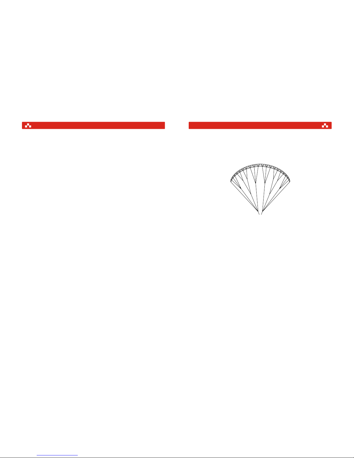
The is a third fulldiagonal rib-construction paraglider. Every third main rib is
attached to the lines and other ribs are attached at A, B, C and D-points thanks to the
diagonal ribs. These ribs lead to top surface of canopy.
The glider is delivered with a standard set-up and its speed can reach 41-44 km/h
depending on the weight of the pilot and equipment. The brake-lines should always be
adjusted so that the first brake-lines just come under tension when the brake handles
have been pulled 5 - 10 cm.
The test results relate to this brake-line adjustment. In extreme situations other settings
may lead to the glider reacting differently. To be able at all times to react quickly enough
to possible problems; you should not let go of the brake handles during the flight (it may
be possible to hold both handles in one hand). Alter the line length to bring the handles to
a suitable height when using your harness.
An optimal outfit should be a matter of course for every paraglider pilot. Always wear
stout footwear, a helmet, and gloves. Clothing should be warm and allow sufficient
freedom of movement. A rescue-system can be life-saving in case of an irremediable
disturbance of the canopy, collapse in the air or material failure, and is therefore
imperative.
SPICE
NOTE!! If in doubt about the brake-line adjustment, it is preferable to leave them too
long, as any necessary shortening can easily be achieved by wrapping them round your
hand.
Page 4
5
Speed system
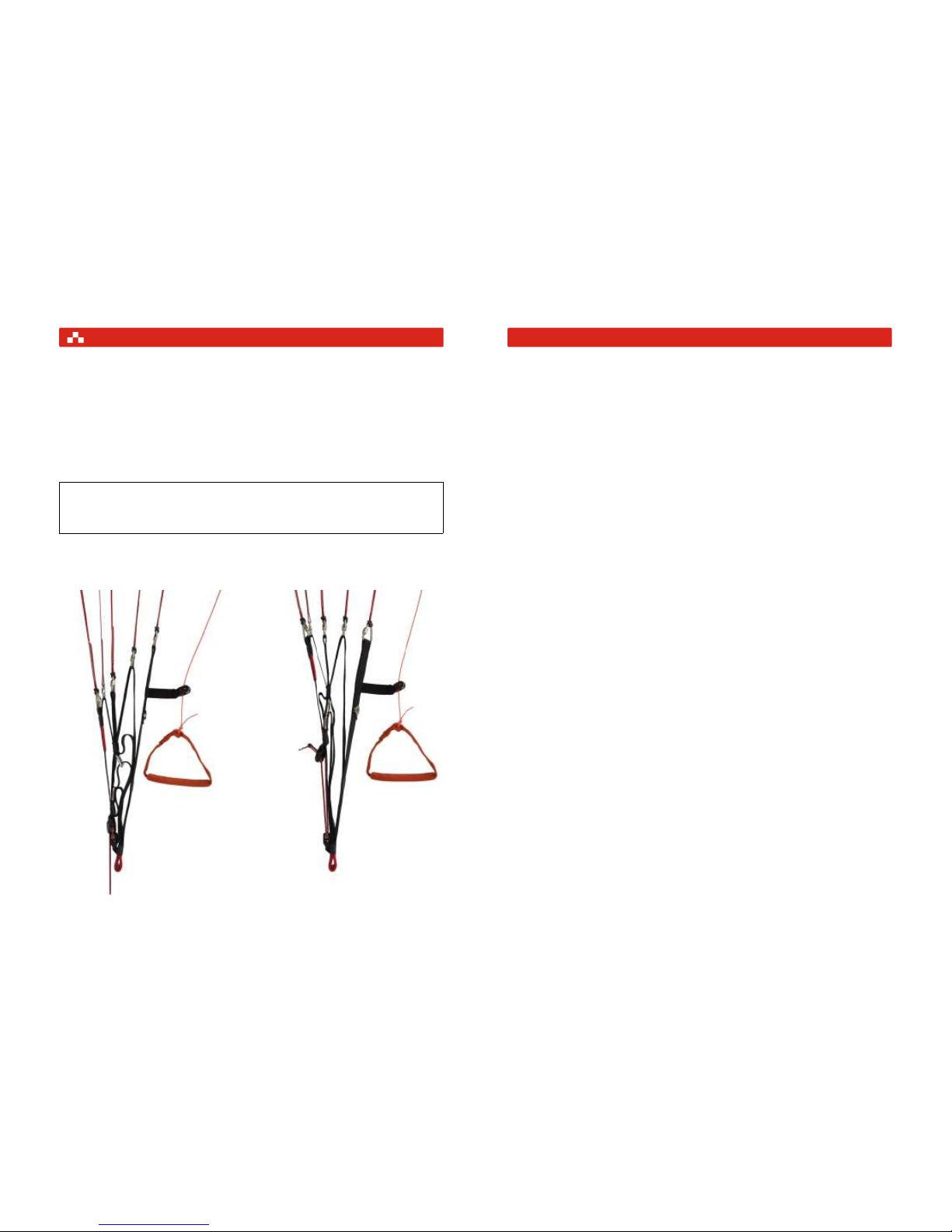
T o fly faster than trim speed the is equipped with a foot operated original speed
system. When in use, it lowers the angle of attack. is designed with a 4-riser
system to further improve safety.
has a very wide speed range. The highly effective speed system of the
allows a 10 - 12 km/h gain in speed.
SPICE
SPICE
SPICE SPICE
Riser A B C D
Trimmposition 45,0 cm 45,0 cm 45,0 cm 45,0 cm
Accelerated 29,0 cm 31,5 cm 38,0 cm 45,0 cm
A A1 B C D
A A1 B C D
6
New glider check and before every flight check
Forward launch
Rear launch
In additional to all the usual pre-flight checks, please pay particular attention to the items
in the following checklist:
1. Inspection of canopy for tears or damage, especially the seams which join the ribs to
the upper and lower surfaces, but also the area of the attachment tapes and brake-line
connections.
2. Inspection of the attachment tapes for damage to the stitches. It is also important to
check the attachment tapes and brake-lines for tangles. The line lengths must be
checked after 50 hours flying time and whenever the flight behaviour of the glider
changes.
3. Inspection of the risers and maillons for faultless condition. Special inspection of the
maillons for traces of corrosion under the lines.
4. Inspection of the knotting of the steering handle to the brake-lines. The brake-lines
must run freely.
5. Inspection of the harness. The harness must show no signs of wear or other damage.
You must also check the harness after a hard landing.
6. Check whether the rescue-system is correctly installed and secured.
7. Inspection of the karabiner. Inspection of the attachment and securing of the karabiner .
8. Inspection of the paramotor.
Find a suitable take-off spot, from which you can abort the take-off at any point. After
checking the glider, following the checklist, lay it out with the cell-openings upwards so
that the canopy forms the shape of a horseshoe. In a strong wind don't spread the
canopy too far, so that there is less resistance when pulling up.
This is possible in almost all wind conditions except strong headwinds. It is essential to
stand in line with the canopy, especially when the glider has longer lines. Before take-off,
place yourself centrally at the gliders axis. Let the B C and D-risers fall into the crook of
your arm and pull the canopy dynamically up by the A-risers. The stronger the headwind
the less run-up you need to pull the canopy up. As soon as the glider is above you, stop
pulling on the A-risers. Now do a visual check upwards, to see if the canopy is completely
open. Otherwise, abort the take-off. Now accelerate continuously until you lift off. In a
weak headwind it is easier to take-off if after reaching minimum flying speed you pull the
brakes slightly. After the take-off, gently release the brakes again.
T o be used in moderate to strong headwinds. If the headwind is too strong, take some of
the pressure out of the canopy by taking in one or both of the brake-lines (or the Crisers).
Checklist
Take-off
WARNING!! Do not use the forward launch in very strong winds. Make sure you don't pull
the risers too much towards yourself or downwards as this can result in a frontal collapse,
or in an asymmetric take-off.
FLYING OPERATIONS
Page 5

7
Flight
Steering
Approach and landing
Always fly with sufficient clearance from the terrain. The glides best with open
brakes, descends best with lightly applied brakes. In turbulence fly with brakes lightly
applied to avoid canopy collapse. If the canopy pendulums forward, this should be
corrected by prompt braking. A pendulum movement of the canopy backwards is
corrected by loosening the brakes in good time.
Turns can be initiated using the brakes in two different ways.
The pilot pulls the brake on the side to which he wishes to turn. T o minimise sinking, the
brake on the outside of the curve is lightly applied.
The pilot pulls the brake on the side to which he wishes to turn and shift his weight to the
same side. Turns can also be flown with the harness alone, by shifting the weight to the
inside of the curve. This weight shift has a greater effect, the more loosely the chest-strap
is fastened. An optimal steering technique is achieved by a combination of braking and
weight shifts. It is pilot's skill to use both of these techniques specially in thermals.
A further possibility for steering is best limited to emergencies (if the brake-lines break, for
example). This entails gently pulling the front (watch out for collapse of the canopy) or on
D-riser (beware asymmetrical stall). We recommend that you do not use this form of
steering in normal flight.
To avoid stressful situations in the approach to landing, it is important to initiate the
process at an adequate altitude. This leaves you enough time to observe and
appropriately deal with wind direction and any other aircraft in your vicinity.
The final approach should generally be made into the wind and with fully released
brakes, in order to maintain maximum energy in the glider. If the air is turbulent, it is
better to land lightly braked to minimise the possibility of the canopy collapsing. In order
to land on your feet, rather than lying on your back, you will need to lean forward in the
harness not lower than 5 m above the ground. At an adequate height (about 1-2 m above
the ground), pull both brakes fully down until the glider is sufficiently slowed.
In a light headwind pulling the brakes only lightly is enough to give a soft landing. In a
calm, or even tailwind, you must pull the brakes as abruptly as possible. This
dynamically increases the angle of attack and gives you the maximum braking effect.
SPICE
Turns with brakes
Turns with brakes and weight shifting
8
Flight with speed system
Towed and motorized flight
T o make faster flight possible, the is equipped with a special speed system.
T o accelerate the paraglider we recommend the following steps:
a) extend the speed bar
b) use the speed bar to control speed
Never activate the speed system in turbulence, at low altitude, or when approaching a
landing (the lower angle of attack results in less stability despite the higher speed).
The is suitable for towed flight, and was designed for paramotoring.
has no tendencies towards deep stall/parachuting. Therefore we allow towlaunched flights with a similar techniques to that described above. There is sufficient
margin to counter-steer the glider in a normal towing situation. Make sure you use proper
equipment, experienced personnel and all relevant safety precautions for towing.
This section describes flying conditions which can be deliberately induced, or which can
develop unintentionally due to turbulence or pilot error. Any pilot who flies through
turbulence is sure to be faced with these special flight conditions at some point. So take a
good look at these flight manoeuvres or prepare for them by SIV (safety training over
water). Mastering these flying conditions significantly improves your active flight safety.
Sufficient height, as well as the carrying of a reserve parachute, is imperative.
SPICE
SPICE
SPICE
Note!! However, motorized flying has been made with great success due to its very easy
take-off characteristics, stability and good handling, always use certified combinations
of engine - harness - glider. If in doubt check with your federation.
WARNING!! Please always ensure that the brake lines are adjusted to the lengths
recommended here. Setting them shorter could lead to a tendency to stall during towed
flight. Apart from this, there are no special procedures.
WARNING!! The SPICE is not suitable for jumps from aircraft.
WARNING!! All the critical flight conditions described here require thorough knowledge;
otherwise carrying them out may be very dangerous. Sufficient height above the ground
is imperative. Bear in mind that all disturbances of the canopy can increase the sink rate
by 2 - 10 m/sec, depending on the degree of disturbance. Carrying out these
manoeuvres wrongly may lead to a crash.
EXTREME AND CRITICAL FLIGHT MANOEUVRES
Page 6

9
Collapse of the canopy
Remember this is a glider with controllable reactions to disturbances in the air.
Whenever in doubt, let up the brakes and let the glider fly. The glider has a high internal
pressure, resistance to tucking and very high degree of passive safety. It is
recommended that at this stage you already start to practising an active flying style. The
key to active piloting is keeping the glider above your head at all times. We recommend
in principle that you hold the brake handle in your hand whenever possible, or fly with
your hands through the brake handles, to allow you to react immediately to any possible
disturbances.
This form of collapse occurs most frequently, caused by turbulence.
Pull the outermost A-line slowly down, until the edge of the canopy folds in. The canopy
collapses furthest if you pull A-riser violently down. This causes up to 70 % of the leading
edge to close up, and results in the canopy going into a spiral towards the collapsed side.
If the harness is too loosely adjusted, in a more extreme collapse you will fall in the
direction of the folded-in side, thus unintentionally magnifying the canopy's tendency to
turn.
Recovery
Basically the will re-open by itself from closures of up to 70% by turning of 90° 270°.
The time this takes, and the associated loss of height, can however be noticeably
reduced by appropriate action by the pilot. Apply opposite brakes on the un-collapsed
side, the outside of the curve, to stop the turning movement of the canopy. If you react
immediately, 30% brake on the open side should suffice to hold the canopy on a straight
course.
WARNING!! If you fly with your hands through the brake handles, you may lose valuable
time for activating the rescue system.
WARNING!! Especially in turbulence, you must first stop the canopy turning, before you
pump out the collapsed side. When the canopy is stable again, open it by pulling the
brake lines on the closed side. If it is tangled, pumping the brake line should help.
WARNING!! Take care to avoid applying too much brake when pumping out the
Asymmetrical collapse
Initiation
SPICE
10
WARNING!! In the case of a cravat which pumping of the brakes fails to release - apply
50% -70% brake on the open side of the canopy to stop rotation. Then pull the caught
line carefully to release it then pump out the affected side. Take care to avoid applying
too much brake when pumping out the deflation, as this may disrupt the airflow over the
canopy and lead to a stall.
NOTE!! usually opens from frontal tuck by itself. If counter braking, be careful - do
not brake too much. You could cause glider to begin a full stall with following surge
forwards.
Symmetrical collapse - "Big-Ears"
Frontal deflation
Initiation
Whilst maintaining contact with the brakes, grip the outermost A-line. Work your hands
as high as possible on this A-line, until you have enough to be able to pull on them
without pulling (A-risers as well). Pull outer A-lines down simultaneously . The further you
pull the A-lines, the greater the area of canopy that will collapse (and the greater will be
the sink rate).
Recovery
As soon as you release outer A-lines,, the opens independently . You can speed
up its opening by light braking. If in extreme cases the lines get tangled, pumping (pulling
repeatedly) the brake lines should help.
If you feel strong turbulence coming, first step off the speedbar. Sometimes you may
have to pull both brakes to avoid a deflation.
Initiation
Hold the brake handles in your hands and grip both A-risers at the level of the maillons.
Now pull down far enough to make the whole leading edge fall in (the further you pull, the
more area folds in).
Recovery
You release the A-risers immediately, the opens by itself and the glider will
recover with a small surge. Y ou can speed up this process by light braking. If the A-risers
are held too long, the canopy could fold in the middle with the wing tips going forward.
SPICE
SPICE
SPICE
Page 7

12
11
Recovery
Release the riser at first rapidly but then gently. After the B-line stall on no account just let
go of the B-risers, as this can cause overloading. As soon as the risers have been
released, the will usually fly normally of its own accord. Otherwise you have two
possibilities:
1. Pull the A-risers, until the canopy regains forward speed. Don't pull too far,
or a frontal tuck will develop.
2. Pull the brake lines until the canopy wants to fall backwards, and then instantly open
both brakes symmetrically. As a result the canopy will shoot forwards, thus regaining
forward speed.
So begin with option 1, and only rely on option 2 when you have enough experience with
the manoeuvre.
If you find yourself in an unintentional spin and you are high enough, you should:
1. Release the brakes immediately. The glider will stop rotating, if it does not apply
sufficient outside brake to stop rotation.
2. Gently apply the brakes to avoid a central collapse of the canopy and the possibility of
a cravat (one of the tips becoming entangled in the lines).
This is included only to expand your knowledge of how the canopies performance. Not
recommended as a descent technique.
Initiation
T ake wraps until the glider is lightly braked (when the hands are right up). Now gently pull
both brake lines, until the canopy falls away behind - at this point, dynamically pull the
brakes fully down. Press your hands against your body. The glider is now over you, with
the wing tips flapping. As a result you sink rapidly with no forward movement.
SPICE
WARNING!
NOTE!! In the case of a cravat which pumping of the brakes fails to release - apply 50% 70% brake on the open side of the canopy to stop rotation. Then pull the caught line
carefully to release it then pump out the affected side.
WARNING!! If you are LOW and are in an unintentional spin, or if the canopy is caught in
a cravat USE YOUR RESERVE.
Spin (negative spirals)
Full stall
Stalls
Turbulence or rapid braking can lead to a pendulum effect, and thus to changes in the
angle of attack. In extreme cases this can make the airflow break away from the upper
surface of the canopy even without the brakes being activated.
Initiation
Pull the brakes slowly down until you have no more forward speed. The canopy now
loses internal pressure and the lower surface pushes further and further up between the
suspension points. The loss of internal pressure is greater the longer the glider is held in
this situation. During the parachutal stall the canopy always remains open.
You will probably have to feel for the right brake position at first. If you apply too much
brake, the canopy falls away backwards and the glider finds itself on the brink of a full
stall. Loosen the brake lines immediately, until the canopy is once more above you. If you
hesitate too long, the canopy will surge forwards.
Recovery
As soon as you release both brakes, symmetrically, the glider will independently recover
from the parachutal stall.
Initiation
Put your hands through the brake handles and grip the B-risers at the height of the
maillons. Now pull the B-risers slowly down, until the canopy folds (parallel to its long
axis). The glider will now stabilise itself and sink rapidly, with virtually no forward speed.
Keep hold of the B-risers throughout the manoeuvre.
WARNING!! All canopies need some time after a stall (in extreme cases a couple of
seconds) before the airflow builds up again. You should therefore carry out all
manoeuvres involving stalls at an adequate height, as it will take a certain amount of time
before the glider flies with its normal sink rate.
WARNING!! In a parachutal stall, asymmetrical application of the brakes can lead to a
spin. If you must land from a parachutal stall, on no account apply the brakes very close
to the ground, as a reduction in area increases the descent rate.
Parachutal stall with steering lines
B-line stall
Page 8

13
Recovery
Let go fluently both brakes simultaneously until 90% of leading edge reopen, then
release brakes rapidly. The glider ends the full stall on its own without surging forward.
SPICE has very effective spiral dive. This allows rapid descent without stalling.
Initiation
Weight-shift and pull the brake on one side gradually. Let the glider accelerate for two
turns and enjoy the growing speed and high G-force.
You can achieve sink rates up to 20 m/s.
Once you have entered the spiral you can control your descent rate and bank angle with
weight shift and brakes. We recommend lightly applying the outer brake to avoid
asymmetrical collapse on outer side of canopy.
Recovery
Weight-shift to a normal flying position and stop application of both brakes. The glider
stops spiral diving by itself in 360 degrees.
If you apply inner brake and decelerate the glider for two or three turns, big pendulum
effects can be avoided.
WARNING!! If the brakes are released rapidly and asymmetrically, the glider may turn
through almost 90 degrees and suffer an extensive asymmetric collapse.
WARNING!! Some gliders have a tendency to stay in the spiral when the sinkrate
exceeds around 15 m/s, depending on weight-shifting, wing loading and G-force. In fact
most gliders need a counter-input to end a turn. With weight-shifting to the normal sitting
position SPICE will however come out of the spiral without pilot input. Practise spiralling
with caution and lesser sinkrates to get a feel for the gliders behaviour. A pilot who is
dehydrated or not accustomed to spiralling can lose consciousness in a steep spiral
dive!
Spiral dive
14
Fly as far as possible from steep rises, to give yourself space to lose height.
Sink rate approximately 2-4 m/sec
Sink rate approximately 4-6 m/sec
This allows rapid descent without stalling. Sink rate, depending on pilot, 5-15 m/sec
Sink rate approximately 5-10 m/sec
- End the stall with sufficient time for the airflow to re-establish itself.
In principle, always fly in such a way that you do not need to lose height in a hurry.
The SPICE is produced from the best materials (see Material Description). The glider
must be checked as a minimum, every year or after 100 flying hours. Do not step on the
lines. Although the lines were tested with „DHV-bend test“ they can be damaged if
stepped on whilst on a hard surface, or if they come into contact with sharp objects.
If this happends contact your dealer for replacement lines. The lines must be checked
after every 50 hours flying time and whenever the flight behaviour changes. Consult your
dealer or MAC ltd. T ears in the canopy must be professionally sewn. Adhesive patches
are only adequate for very minor damage. The glider must always be kept cool and dry. If
possible it should be stored lightly folded in a well-ventilated place. Protect the glider
from dampness and sunlight. Exposure to UV degrades the fabric. A damp or wet
canopy must be air-dried in a shady place. Do not expose the glider to temperatures of
greater than 50 degrees C, as this can cause softening and shrinking of the attachment
tapes. Clean the canopy only with warm water or a dilute soap solution. Do not use
solvents.
SPICE is delivered with a stuff-sack, T-shirt, MAC rucksack, speedbar and user manual.
Happy landings
Peter Recek - Constructeur
MAC PARA TECHNOLOGY
Symetrical collapse - "big ears"
Speed system and "big ears"
Spiral dive
B-line stall
Important!
DESCENT RATES
MAINTENANCE AND REPAIR
Page 9
15
FABRIC OF CANOPY
LINES
BRIDLE (ATTACHMENT LINES)
RISER
THREAD
MAILLONS
NCV - PORCHER MARINE Wassoilles Rue du Ruisseau B.P. 710
38290 ST. QUENTIN FALLAVIER, FRANCE
Extrados - SKYTEX S9017 E77A,E38A - 100% nylon 6.6 , 33 Dtex, 40 g/m2
Intrados - SKYTEX S9017 E38A - 100% nylon 6.6 , 33 Dtex, 36 g/m2
Main ribs - SKYTEX S 9017 E29A - 100% nylon 6.6 , 33 Dtex, 40 g/m2
Ribs - SKYTEX S 09017 E38A - 100% nylon 6.6 , 33 Dtex, 40 g/m2
Reinforcement main ribs - Grille Polyester 200 g/m2
Reinforcement ribs - W382 Polyester 180 g/m2
EDELMAN+RIDDER, LIROS
Upper lines - Aramid/Polyester A-6843-080, Breaking Load 80 kg
Middle lines A,B - Aramid/Polyester A-6843-160, Breaking Load 160 kg
Middle lines C,D - Aramid/Polyester A-6843-120, Breaking Load 120 kg
Brake lines - Dynema/Polyester A-7850-100, Breaking Load 100 kg
Main lines D1,D2,D3,C1 - LIROS TSL 90, Breaking Load 90 kg
Main lines C2,C3 - LIROS TSL 140, Breaking Load 140 kg
Main lines A1,B1 - LIROS TSL 220, Breaking Load 220 kg
Main lines A2,A3,B2,B3 - LIROS TSL 380, Breaking Load 380 kg
Wing tip line - Aramid/Polyester A-6843-080, Breaking Load 80 kg
Main brake line - Dynema/Polyester A-7850-240, Breaking Load 240 kg
STAP a.s.
407 80 VILEMOV, CZECH REPUBLIC
STAP-POLYESTERBRIDLE 13 mm, Breaking Load 95 kg
MOUKA TISNOV ltd
Koráb 133, 66601 Tišnov, Czech Republic
Polyester 367 040 025 912 25x1,5 mm Breaking Load 800 kg
AMANN SPONIT ltd
Dobronická 635, 148 25 PRAHA 4, CZECH REPUBLIC
Lines - SYNTON 60 Breaking Load 3,5 kg, Mean lines - SERABOND 60 Br. Load 7 kg
Canopy - SYNTON 40 Breaking Load 6 kg, Riser - SYNTON 30 Breaking Load 12 kg
ELAIR SERVIS
NIRO TRIANGLE 200 - Max. Load 200 kg
MATERIAL DESCRIPTION
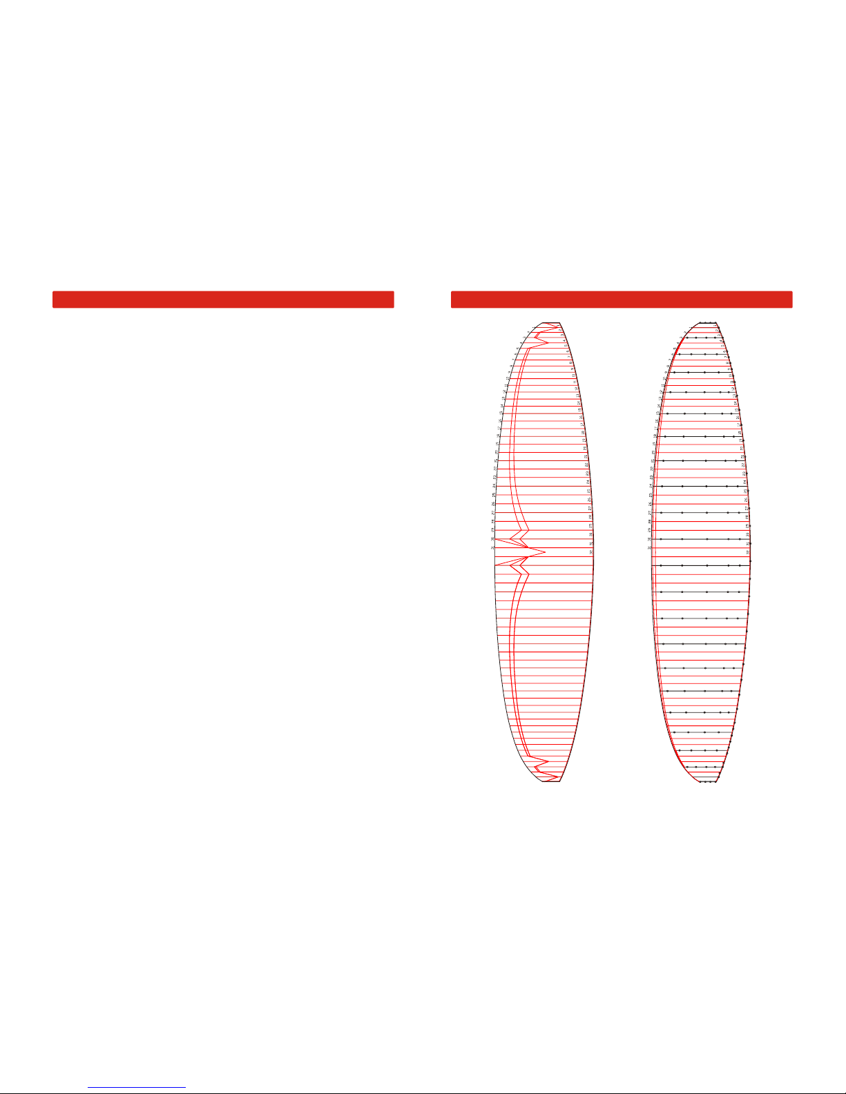
GROUND PLAN
16
Page 10
17
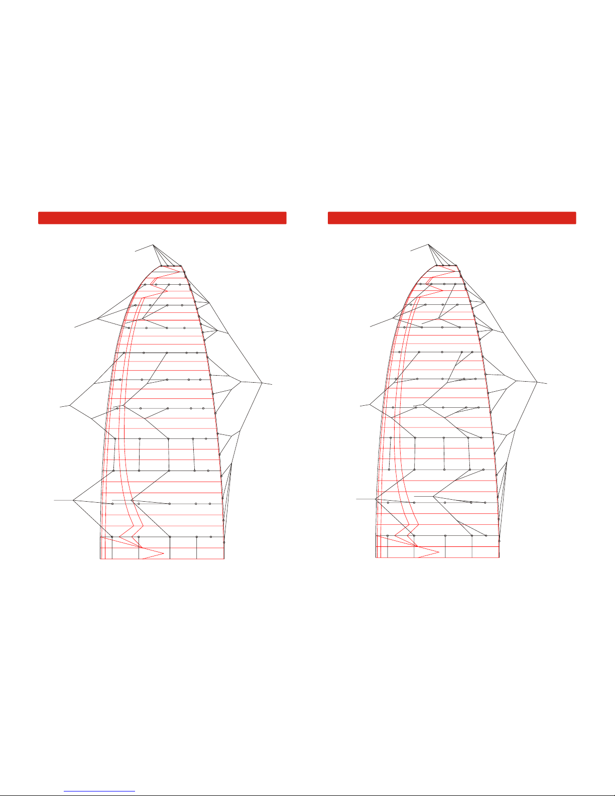
LINE PLAN AC
stA
A3
A12
s1A
s2A
A15
A18
A21
A24
A27
A30
mA1
mA2
mA3
A6
A9
C3
C12
s1C
s2C
C15
C18
C21
C24
C27
C30
mC1
mC2
mC3
C6
C9
st0
stB
stC
stD
br1
br2
br3
br4
br19
br25
br20
br26
br27
mBR
br21
br22
br23
br24
br5
br6
br7
br8
br9
br10
br11
br12
br13
br14
br15
br16
br17
br19
18
LINE PLAN BD
stA
B3
B12
s1B
s2B
B15
B18
B21
B24
B27
B30
mB1
mB2
mB3
B6
B9
D3
D12
E12
s1D
s2D
D15
E15
D18
E18
D21
E21
D24
E24
D27
E27
D30
Dt
Dt
Dt
Dt
Dt
Dt
Dt
E30
mD1
mD2
mD3
D6
D9
st0
stB
stC
stD
br1
br2
br3
br4
br19
br25
br20
br26
br27
mBR
br21
br22
br23
br24
br5
br6
br7
br8
br9
br10
br11
br12
br13
br14
br15
br16
br17
br19
Page 11

19
Check-intervals
All paragliders used in flight must be checked at least every 24 months. For paragliders
used by paragliding schools the period is 12 months.
Personnel authorised to carry out checks
A valid flying license and training course by National association are the basis for
permission to carry out paraglider checks
Identification of glider
An identity sticker with details of certification and serial number is attached to the glider.
The porosity should be checked with a porosity meter (JDC). Compare the resultant data
with the producer's manual.
Porosity measures should be taken on at least three points of both the top and bottom
surface. The first point should be placed 20-30 cm from leading edge in the middle of
canopy. Second and third points are placed left and right from first measure point at 25%
of the span. One additional measurement should be made on the top surface of the wing
tip.
The identified time should be higher than 30 second (JDC). In the event of the result
being less than 30 seconds, the result of the check is a fail.
The check of canopy strength should be made with a Bettsometer (B.M.A.A approved
Patent No. GB 2270768 Clive Betts Sales). On the top and bottom surfaces make small
holes with a needle at the Aline attachment points. The exact verification should be made
in accordance with the Bettsometer user manual.
Line strengths should be as specified in accordance with the DHV requirements. One
main line should be taken from each array and have its strength checked with a tensionmeter.
Required strengths should be higher than:
- A + B main lines x measured value > 8 x maximum take-off weight and higher then
800 kg for the A + B arrays.
- C + D mean lines x measured value > 6 x maximum take-off weight and higher then
600 kg for the A + B arrays.
Replacements for damaged lines must be with new original lines. Line lengths are taken
from the lines data page.
Components of the check
Porosity
Overall strength check
Line strength check
MANUAL FOR PARAGLIDER CHECKS
20
Line length measurement
Canopy line-attachment points check
Canopy fabric check
Lines
Connector check
Risers
Final check
Lines should be separated and each line measured under a tension of 5 kg. Measurement
is made from the line karabiner to the canopy according to the DHV method. Rib numbering
begins in the middle of canopy and leads to the wing tip.
Measured full lengths should be documented in the inspection record and are compared
with the DHV type protocol. Lengths should not differ by more than 20 mm. The opposite
sides should be checked for symmetry.
Attachment points should be checked for damage and stretching. Defects, loops and
flares should be repaired.
Ribs, diagonal ribs, top and bottom surface should be checked. Any damage to sewing or
tears to the fabric, which could influence flying characteristics must be repaired.
All lines should be checked for tears, breaks any damage to the sheath or signs of wear.
Special attention should be paid to the sewing of the line loops. Damaged lines must be
replaced.
The results should be documented in the inspection record.
All line carabineers, trimmers (if used), speed systems and pulleys should be inspected for
visible damage. Open or improperly secured connectors should be secured in accordance
with the producers recommendations.
Both risers should be checked for tears, signs of wear or any damage and measured with a
pull of 5 daN strength. Measured data should be documented in the inspection record. The
difference must not be higher then 5 mm when compared to specified lengths.
The glider sticker and check sticker must be inspected for readability and correctness.
The check must be documented with date, signature and stamp on the canopy and in the
user manual.
Page 12
21
Name Company Date Signature & Stamp
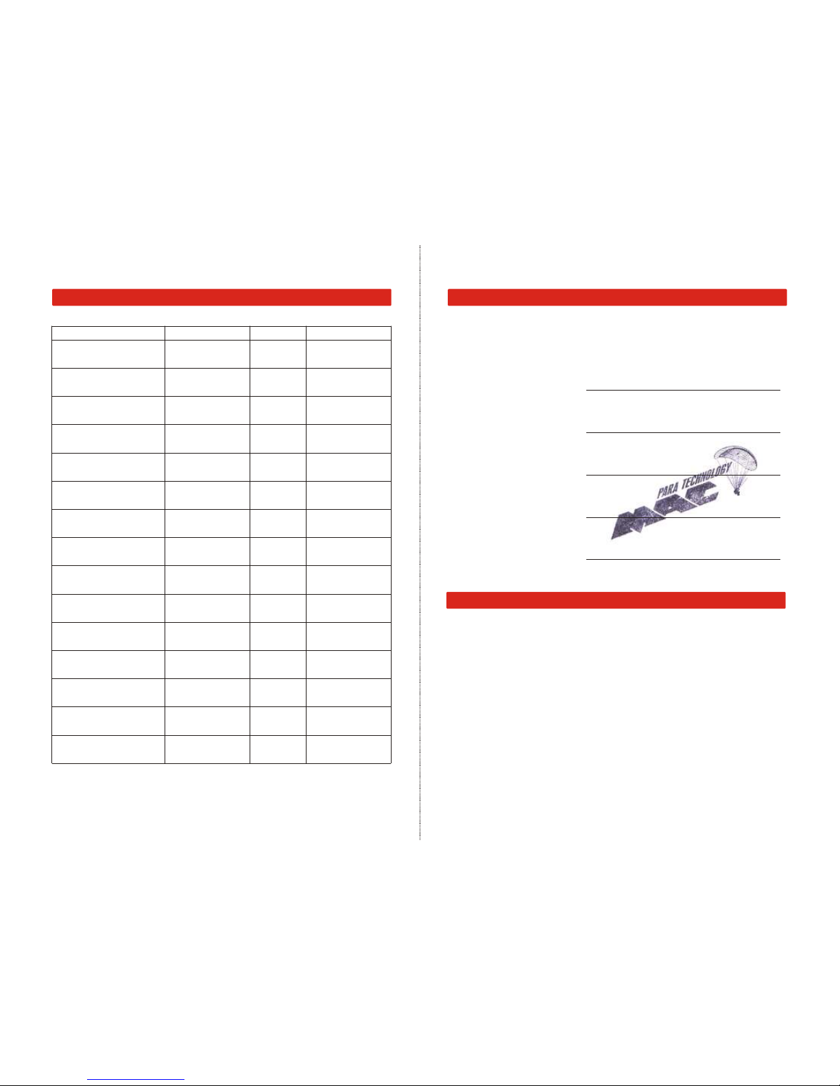
CHECKS
TECHNICAL DATA
SPICE -
Paraglider type:
Serial number:
Test flown on:
by:
Pilot's signature:
Confirmation by dealer:
SPICE SPICE
size
Zoom flat [%] 94 100
2
Area flat [m ] 22,12 25,03
2
Area projected [m ] 19,40 21,96
Span flat [m] 11,33 12,05
Aspect ratio flat 5,8 5,8
Root cord [m] 2,45 2,61
Cells 63 63
Weight [kg] 6,10 6,40
Weight range [kg] 95-125 120-150
Min.speed [km/h] 26-27 26-27
Max.speed [km/h] 41-44 41-44
Top speed (accelerator) [km/h] 57-62 57-62
Glide ratio 8,5 8,5
Min. Sink rate [m/s] 1,10 1,10
M L
TEST FLIGHT CERTIFICATE
 Loading...