

High Power
PIN Diodes
MA4P HIPAX™ Series
V3.00
M/A-COM, Inc.
North America: Tel. (800) 366-2266 ■ Asia/Pacific: Tel. +81 3 3263 8761 ■ Europe: Tel. +44 (1344) 869 595
Fax (800) 618-8883 Fax +81 3 3263 8769 Fax +44 (1344) 300 020
1
Specifications Subject to Change Without Notice.
Features
●
High Power Handling
●
Low Loss, Low Distortion
●
Voltage Ratings to 1000 Volts
●
Passivated PIN Chip – Full Face Bonded
●
Hermetically Sealed
●
Low Inductance Axial Lead, and SMQ
Surface Mount Package Options
●
Available as Chips
Description
M/A-COM’s HIPAX PIN diodes are designed for service in
switch and attenuator applications requiring high power
handling and low distortion. HIPAX PIN diodes incorporate a fully passivated PIN diode chip resulting in
extremely low reverse leakage current. all high voltage
HIPAX PIN diodes are specified at 1 µA reverse current at
the voltage rating. The chip is full face bonded to refractory metal pins on both anode and cathode. The result is
a low loss PIN diode with low thermal resistance due to
symmetrical thermal paths.
HIPAX PIN diodes are packaged in hermetically sealed
ceramic enclosures at temperatures exceeding 300°C.
Package options include: axial leaded and surface mount
packages that have a square, nonrollable outline.
The semiconductor technology utilized in the HIPAX
family draws on M/A-COM’s substantial experience in
PIN diode design. This results in thick intrinsic region
PIN diodes specified with low resistance, low capacitance
and long carrier lifetime parameters.
SMQ Square Outline Surface Mount
The surface mount HIPAX PIN diode is available in
M/A-COM’s unique, square outline, non-rollable SMQ
package design. The SMQ package eases automatic pick
and place indexing and assembly.
Applications
HIPAX PIN diodes are designed for use in a wide variety
of switch and attenuator applications from HF through
UHF at power levels beyond 1 kW CW. These diodes
have been comprehensively characterized to ensure predictable performance.
Design Recommendations
1. Low Distortion Attenuators: MA4P4301B
2. Surface Mount Switches: MA4P7101F
3. Cellular Radio Antenna Switches:
MA4P1200, MA4P1250
Envir onmental Capability
HIPAX PIN diodes are appropriate for use in military,
industrial and commercial applications. They are capable
of meeting the environmental requirements of
MIL-STD-750 and MIL-STD-202. HIPAX PIN diodes are
capable of HTRB screening at 80% of voltage rating at
150°C.
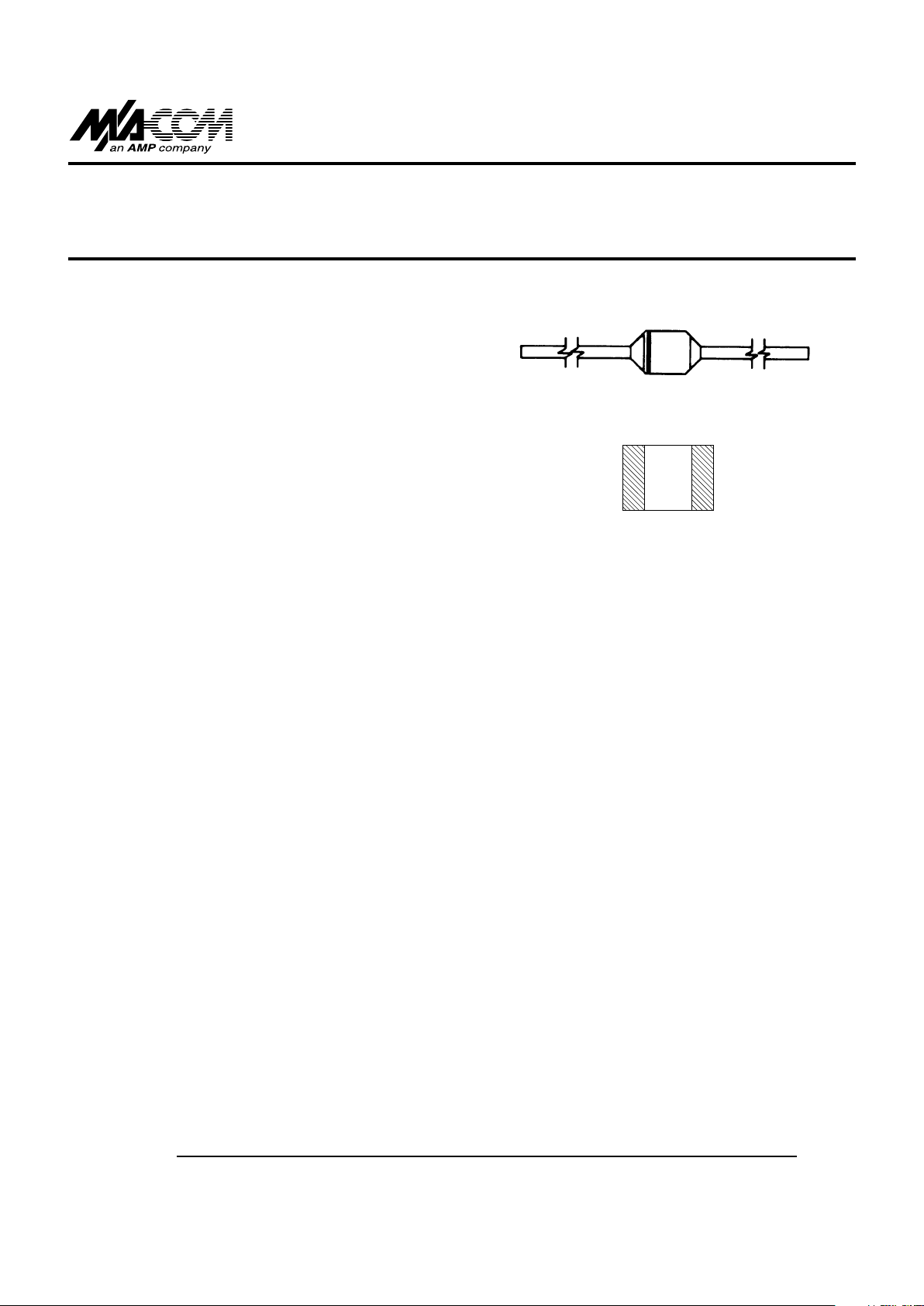
Case Styles
401
1072
High Power PIN Diodes MA4P HIPAX™ Series
V3.00
M/A-COM, Inc.
North America: Tel. (800) 366-2266 ■ Asia/Pacific: Tel. +81 3 3263 8761 ■ Europe: Tel. +44 (1344) 869 595
Fax (800) 618-8883 Fax +81 3 3263 8769 Fax +44 (1344) 300 020
2
Specifications Subject to Change Without Notice.
Voltage Ratings and Model Numbers
Electrical Specifications @ 25°C
Power Dissipation and Thermal Resistance Ratings
Envir onmental Ratings
HIPAX PIN diodes may be supplied with JAN TX level screening. The table
lists some of the MIL-STD-750 environmental tests HIPAX PIN diodes are
designed to meet.
MIL-STD-750
Test Method Description
High Temperature Storage 1031 +175°C, 250 Hours
Temperature Shock 1051 -65°C to +175°C, 20 Cycles
HTRB 1038 809b VR, +150°C, 96 Hours
Moisture Resistance 1021
Fine Leak 1071 Cond. H 1 x 10⁻⁷CC/Sec
Constant Acceleration 2006 20,000 G’s
Vibration Fatigue 2046 20,000 G’s
Solderability 2026
Lead Fatigue 2036.3 Cond. E 3 cycles, 8 oz., 90°,
Bent at Body
Tension 2036.3 Cond. A 2 Ibs., 30 seconds
Absolute Maximum Ratings @ 25°C
Voltage MA4P4000 MA4P4300 MA4P7000 MA4P7100
Rating Series Series Series Series
100 Volts MA4P4001 MA4P4301 MA4P7001 MA4P7101
200 Volts MA4P4002 MA4P4302 MA4P7002 MA4P7102
400 Volts — — — MA4P7104
600 Volts MA4P4006 — MA4P7006 —
MA4P4000 MA4P4300 MA4P7000 MA4P7100
Parameter Symbol Condition Series Series Series Series
Series Resistance (Max) R
s
100 mA, 100 MHz 0.5 Ω 1.0 Ω 0.8 Ω 0.5 Ω
Total Capacitance (Max) C
T
100 V, 1 MHz 2.2 pF 2.0 pF 0.7 pF 1.0 pF
Parallel Resistance (Min) R
p
100 V, 100 MHz 20 kΩ 50 kΩ 200 kΩ 100 kΩ
Carrier Lifetime (Min) T
L
10 mA 6 µs 8 µs 3 µs 2.5 µs
Forward Voltage (Max) V
F
100 mA 1.0 V 1.2 V 1.0 V 1.0 V
Reverse Current (Max) I
R
Voltage Rating 1 µA 1 µA 1 µA 1 µA
I-Region Width (Nominal) W — 175 µm 300 µm 175 µm 100 µm
MA4P4000 MA4P4300 MA4P7000 MA4P7100
Package Style Condition P
D
ø
JC
P
D
ø
JC
P
D
ø
JC
P
D
ø
JC
B 1/4 Inch Total Length 12 W 12.5°C/W 10 W 15°C/W 5 W 30°C/W 6 W 25°C/W
(Axial Leaded) to 25°C Free Air Rating 2.5 W — 2.5 W — 1.5 W — 1.5 W —
F (SMQ Surface Mount) 25°C Contacts 7.5 W 20°C/W 5 W 30°C/W 3 W 50°C/W 3 W 50°C/W
Both B and F Single 1 µs pulse 100 kW — 100 kW — 15 kW — 15 kW —
Both B and F Single 100 µs pulse 5 kW .03°C/W 5 kW 03°C/W 300 W 0.5°C/W 300 W 0.5°C/W
Ordering Information
HIPAX PIN diodes are designated by MA4P followed by four
digits which indicate the voltage rating and series. A package
style letter suffix follows:
To purchase:
MA4P4000 Series, 600V, SMQ package (F)
Order Model No.: MA4P4006F
The same unit in an axial lead package (B) is: MA4P4006B.
Parameter Absolute Maximum
DC Reverse Voltage Voltage Rating
Operating and Storage Temperature -65°C to +175°C
Installation Temperature +250°C, 30 Seconds

High Power PIN Diodes MA4P HIPAX™ Series
M/A-COM, Inc.
North America: Tel. (800) 366-2266 ■ Asia/Pacific: Tel. +81 3 3263 8761 ■ Europe: Tel. +44 (1344) 869 595
Fax (800) 618-8883 Fax +81 3 3263 8769 Fax +44 (1344) 300 020
3
Specifications Subject to Change Without Notice.
V3.00
T ypical Performance Curves
SERIES RESISTANCE AT 100 MHz vs FORWARD CURRENT
(MA4P1200)
CAPACITANCE vs FREQUENCY
(MA4P1200)
Absolute Maximum Ratings @ 25°C
Parameter Minimum Typical Maximum Unit Condition
Voltage Rating 50 — — V I = 10 µA
Series Resistance — 0.5 075 Ω F = 100 MHz
I = 50 mA
Capacitance: MA4P1200 — 1.2 1.5 pF F = 1 MHz
V = 50 V
Parallel Resistance 5 K 10 K — Ω F = 100 MHz
V = 0 V
Carrier Lifetime 2.0 4.0 — µs I = 10 mA
Forward Bias Harmonic 80 90 — dBc F = 100 MHz
Distortion (R2aR3a) P = 30 WA
I = 50 mA
Reverse Bias Harmonic 60 70 — dBc F = 100 MHz
Distortion (R
2a
– R3a) P = 0 dBm
V = 0 V
Forward Voltage — — 1.0 V I = 50 mA
a
a
a a
PARALLEL RESISTANCE vs FREQUENCY AND REVERSE BIAS
(MA4P1200)
HEAT SINK TEMPERATURE vs MAXIMUM POWER DISSIPATION
(MA4P1200)
Note: MA4P1200 available in axial leaded case style.
Parameter Absolute Maximum
Operating and Storage Temp. -65°C to +175°C
DC Reverse Voltage 50 Volts
Power Dissipation:
Free Air 1.5 Watts
1/4 inch spaced to +25°C Contacts
5.5 Watts
Electrical Specifications @ 25°C (MA4P1200)

High Power PIN Diodes MA4P HIPAX™ Series
V3.00
M/A-COM, Inc.
North America: Tel. (800) 366-2266 ■ Asia/Pacific: Tel. +81 3 3263 8761 ■ Europe: Tel. +44 (1344) 869 595
Fax (800) 618-8883 Fax +81 3 3263 8769 Fax +44 (1344) 300 020
4
Specifications Subject to Change Without Notice.
CAPACITANCE vs FREQUENCY AND REVERSE BIAS
(MA4P4000 SERIES)
CAPACITANCE vs FREQUENCY AND REVERSE BIAS
(MA4P4300 SERIES)
PARALLEL RESISTANCE vs FREQUENCY AND REVERSE
VOLTAGE (MA4P4300 SERIES)
T ypical Performance Curves
SERIES RESISTANCE AT 100 MHz vs FORWARD
CURRENT (MA4P4000, MA4P4300 SERIES)
SERIES RESISTANCE AT 100 MHz vs FORWARD CURRENT
(MA4P7000, MA4P7100 SERIES)
PARALLEL RESISTANCE vs FREQUENCY AND REVERSE
VOLTAGE (MA4P4000 SERIES)

High Power PIN Diodes MA4P HIPAX™ Series
M/A-COM, Inc.
North America: Tel. (800) 366-2266 ■ Asia/Pacific: Tel. +81 3 3263 8761 ■ Europe: Tel. +44 (1344) 869 595
Fax (800) 618-8883 Fax +81 3 3263 8769 Fax +44 (1344) 300 020
5
Specifications Subject to Change Without Notice.
V3.00
CAPACITANCE vs FREQUENCY AND REVERSE BIAS
(MA4P7100 SERIES)
CARRIER LIFETIME vs FORWARD CURRENT
PULSED THERMAL IMPEDANCE vs PULSE WIDTH
T ypical Performance Curves (Cont’d)
CAPACITANCE vs FREQUENCY AND REVERSE BIAS
(MA4P7000 SERIES)
PARALLEL RESISTANCE vs REVERSE VOLTAGE
(MA4P7000 SERIES)
PARALLEL RESISTANCE vs FREQUENCY AND REVERSE
VOLTAGE (MA4P7100 SERIES)

High Power PIN Diodes MA4P HIPAX™ Series
V3.00
M/A-COM, Inc.
North America: Tel. (800) 366-2266 ■ Asia/Pacific: Tel. +81 3 3263 8761 ■ Europe: Tel. +44 (1344) 869 595
Fax (800) 618-8883 Fax +81 3 3263 8769 Fax +44 (1344) 300 020
6
Specifications Subject to Change Without Notice.
Case Styles
Style B - Axial Leaded
Case Style 401 — MA4P7000B, MA4P7100B, MA4P1200
Style F- SMQ Surface Mount
Case Style 1072 — MA4P7000F, MA4P7100F
Case Style 402 — MA4P4000B, MA4P4300B
INCHES MILLIMETERS
DIM. MIN. MAX. MIN. MAX.
A 0.080 0.095 2,032 2,413
B 0.115 0.135 2,921 3,429
C 0.008 0.030 0,203 0,762
INCHES MILLIMETERS
DIM. MIN. MAX. MIN. MAX.
A — 0.190 — 4,83
B — 0.090 — 2,29
C 0.975 — 24,8 —
D 0.027 0.029 0,69 0,74
INCHES MILLIMETERS
DIM. MIN. MAX. MIN. MAX.
A — 0.230 — 5,842
B — 0.140 — 3,556
C 0.975 — 24,765 —
D 0.039 0.041 0,991 1,041
Case Style 1091 — MA4P4000F, MA4P4300F
Bonding Pad for SMQ Diodes
INCHES MILLIMETERS
DIM. MIN. MAX. MIN. MAX.
A 0.138 0.155 3,51 3,94
B 0.180 0.200 4,57 5,08
C 0.008 0.030 0,203 0,762
Case Styles 1072 Case Styles 1091
DIM. IN. MM IN. MM
A 0.093 2,36 0.150 3,81
B 0.050 1,27 0.050 1,27
C 0.060 1,52 0.100 2,54
 Loading...