

Page 1

Installation Manual
MM101259V1 R1A
™
AGUAR
J
725M
Mobile Radio
Page 2

TABLE OF CONTENTS
SAFETY INFORMATION....................................................................... 3
SAFETY TRAINING INFORMATION.................................................. 4
INTRODUCTION ..................................................................................... 6
UNPACKING AND CHECKING EQUIPMENT .................................. 7
PLANNING THE INSTALLATION..................................................... 10
EQUIPMENT REQUIRED.................................................................... 12
INSTALLATION .................................................................................... 13
RUNNING CABLES......................................................................... 13
Power Cable .............................................................................. 14
Accessory Cable ........................................................................ 15
Ignition Sense (All Applications) .............................................. 17
Control Cable (Remote Mount Only) ........................................ 19
CONTROL UNIT MOUNTING ....................................................... 19
SPEAKER ......................................................................................... 21
MICROPHONE HANGER AND/OR HOOKSWITCH MOUNTING21
SIREN & LIGHT............................................................................... 22
RADIO MOUNTING AND FINAL HOOK-UP ............................... 23
Front Mount............................................................................... 23
Remote Mount Installation ........................................................ 25
DUAL CONTROL UNITS ..................................................................... 29
PRE-INSTALLATION PROGRAMMING PROCEDURE WITH PC
PROGRAMMER - FRONT MOUNT............................................... 29
PRE-INSTALLATION PROGRAMMING PROCEDURE WITH PC
PROGRAMMER - REMOTE MOUNT............................................ 32
INSTALLATION INSTRUCTIONS FOR FRONT MOUNT DUAL
CONTROL UNITS............................................................................ 35
INSTALLATION INSTRUCTIONS FOR REMOTE MOUNT DUAL
CONTROL UNITS............................................................................ 37
FIELD PROGRAMMING WITH PC PROGRAMMER – DUAL
CONTROL UNITS............................................................................ 41
Field Programming Procedure for Front Mount Dual Control
Units .......................................................................................... 41
Field Programming Procedure for Remote Mount Dual Control
Units .......................................................................................... 43
DUAL RADIO UNITS ............................................................................ 46
PRE-INSTALLATION PROGRAMMING PROCEDURE WITH PC
PROGRAMMER – DUAL RADIO UNITS...................................... 46
This manual is published by M/A-COM Private Radio Systems, Inc., without any warranty.
Improvements and changes to this manual necessitated by typographical errors, inaccuracies of current
information, or improvements to programs and/or equipment, may be made by M/A-COM Private Radio
Systems, Inc., at any time and without notice. Such changes will be incorporated into new editions of this
manual. No part of this manual may be reproduced or transmitted in any form or by any means, electronic
or mechanical, including photocopying and recording, for any purpose, without the express written
permission of M/A-COM Private Radio Systems, Inc.
Copyright© 2001 M/A-COM Private Radio Systems, Inc. All rights reserved.
2
Page 3

SAFETY INFORMATION
The operator of any mobile radio should be aware of certain hazards
common to the operation of vehicular radio transmissions. A list of
several possible hazards is given:
1. Explosive Atmospheres - Just as it is dangerous to fuel a vehicle
with the motor running, similar hazards exist when operating a
mobile radio, be sure to turn the radio off while fueling the vehicle.
Do not carry containers of fuel in the trunk of the vehicle if the radio
is mounted in the trunk.
2. Interference to Vehicular Electronics Systems - Electronic fuel
injection systems, electronic anti-skid braking systems, electronic
cruise control systems, etc., are typical electronic systems that may
malfunction due to the lack of protection from radio frequency
energy present when transmitting. If the vehicle contains such
equipment, consult the dealer and enlist their aid in determining the
expected performance of electronic circuits when the radio is
transmitting.
3. Dynamite Blasting Caps - Dynamite blasting caps may be caused to
explode by operating a radio within 500 feet of the blasting caps.
Always obey the "Turn Off Two-Way Radios" signs posted where
dynamite is being used.
When transporting blasting caps in your vehicle:
A. Carry the blasting caps in a closed metal box with a soft lining.
B. Leave the radio OFF whenever the blasting caps are being put
into or removed from the vehicle.
4. Liquefied Petroleum (LP) Gas Powered Vehicles - Mobile radio
installations in vehicles powered by liquefied petroleum gas with the
LP gas container in the trunk or other sealed-off space within the
interior of the vehicle must conform to the National Fire Protection
Association standard (NFPA) 58 requiring:
A. The space containing the radio equipment shall be isolated by a
seal from the space containing the LP gas container and its
fittings.
B. Outside filling connections shall be used for the LP gas
container.
C. The LP gas container shall be vented to the outside of the
vehicle.
3
Page 4

SAFETY TRAINING INFORMATION
Your M/A-COM radio generates RF electromagnetic
energy during transmit mode. This radio is designed for
and classified as “Occupational Use Only,” meaning it
must be used only during the course of employment by
individuals aware of the hazards and the ways to
WARNING
This radio has been tested and complies with the FCC RF exposure limits
for “Occupational Use Only.” In addition, your M/A-COM radio
complies with the following Standards and Guidelines with regard to RF
energy and electromagnetic energy levels and evaluation of such levels
for exposure to humans:
• FCC OET Bulletin 65 Edition 97-01 Supplement C, Evaluating
Compliance with FCC Guidelines for Human Exposure to Radio
Frequency Electromagnetic Fields.
minimize such hazards. This radio is NOT intended for
use by the “General Population” in an uncontrolled
environment.
• American National Standards Institute (C95.1 – 1992), IEEE
Standard for Safety Levels with Respect to Human Exposure to
Radio Frequency Electromagnetic Fields, 3 kHz to 300 GHz.
• American National Standards Institute (C95.3 – 1992), IEEE
Recommended Practice for the Measurement of Potentially
Hazardous Electromagnetic Fields – RF and Microwave.
To ensure that your exposure to RF electromagnetic
energy is within the FCC allowable limits for
occupational use, always adhere to the following
CAUTION
guidelines:
• DO NOT operate the radio without a proper antenna attached, as this
may damage the radio, and may also cause you to exceed FCC RF
exposure limits. A proper antenna is the antenna supplied with this
radio or an antenna specifically authorized by M/A-COM for use
with this radio.
• DO NOT transmit for more than 50% of total radio use time (50%
duty cycle). Transmitting more than 50% of the time can cause FCC
RF exposure compliance requirements to be exceeded. The radio is
transmitting when the “TX” LED in the radio’s display is
4
Page 5

illuminated. Pressing the “PTT” button on the microphone will
cause the radio to transmit.
• ALWAYS use M/A-COM authorized accessories (antennas,
speaker/mics, etc.). Use of unauthorized accessories may cause the
FCC Occupational/Controlled Exposure RF compliance
requirements to be exceeded.
• ALWAYS keep at least 20 cm (8 inches) between the antenna and
user/bystanders while transmitting. This radio has been tested and
found to be compliant with Specific Absorption Rate (SAR) limits
for uncontrolled exposure at a distance of 20 cm (8 inches) or more
using a 50% duty cycle.
The information listed above is provided to make the user aware of
an RF exposure and what to do to assure that this radio operates
within the FCC RF exposure limits of this radio.
5
Page 6

INTRODUCTION
This manual contains installation instructions for the J
AGUAR
725M
Mobile Radio Unit and associated accessories. These instructions cover
the mounting and cabling of the radio; interconnection and wiring
diagrams are provided for reference. Before installation the radio should
be programmed using an IBM-compatible personal computer and the
following items:
Programming Cable TQ3377
ProGrammer PC Software TQ3385
or
Conventional ProGrammer PC Software TQ3389
6
Page 7

UNPACKING AND CHECKING EQUIPMENT
Carefully unpack the radio and identify each item in the shipping
container as listed below. If damage has occurred to the equipment
during shipment, file a claim with the carrier immediately. The available
options for the J
AGUAR
725M Mobile Radio are covered in Table 1.
• J
AGUAR
725M Mobile Radio Unit
• Microphone HBMC3Z or HBMC5L
• Speaker HBLS1H or HBLS1U
• Power Cable HBCF9A
• Control Cable HBCG5R or HBCE5S
• Front Mount Bracket Kit HBMAxx
or
• Remote Mount Kit HBMAxx
with
• Control Unit Mount Kit HBMA3J
• Operator's Manual MM101258V1
• Installation Manual MM101259V1
Figure 1 - J
AGUAR
725M Mobile Radio Components and Mounting
Hardware
7
Page 8
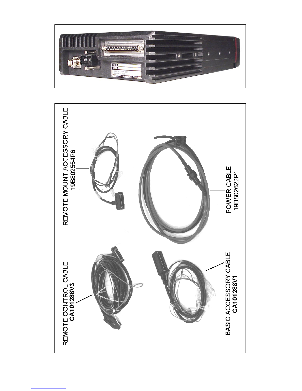
Figure 2 – Rear Angle View of Radio
8
Figure 3 - Cables
Page 9

Table 1 - J
AGUAR
725M
Mobile Radio Optional Accessories
Option Description Part Number
HBAN1L 800MHz ¼ Wave Whip Antenna 19B209568P5
HBCF9A Power Cable 19B802622P3
F
RONT MOUNT
HBCE5R Extended Option Accessory Cable CA101288V2
R
EMOTE MOUNT
HBCE5S Extended Option Control Cable CA101288V4
HBCE5T Extended Option Accessory Cable 19B802554P7
D
UAL CONTROL
HBCE5Z Dual Control Cable, Remote 9.0m 19B802554P9
D
UAL RADIO
HBCE7A Dual Radio Cable, Remote 2.0m CA101288V10
HBCLxx Dual Radio Extension Cable for Field Programming,
Keyloading, and Mobile Data Applications
HBMA3J Mounting Bracket Kit, Remote Control Unit 344A4584G2
HBMAxx Mounting Bracket Kit, Front Mount Radio
HBMAxx Mounting Bracket Kit, Remote Mount Radio
HBMK3E Keycap Kit, Scan Control Unit 19C852359P101
HBMK3F Keycap Kit, System Control Unit 19C852359P102
HBMN1A Microphone Hanger 344A4678P1
CA101288V30
9
Page 10

PLANNING THE INSTALLATION
Figure 4 provides an example of a typical mobile radio remote mount
installation. Before starting, plan the radio installation carefully so that it
will be:
• safe for the operator and passengers,
• convenient for the operator to use,
• neat,
• protected from water damage,
• easy to service,
• out of the way of auto mechanics, and
• out of the way of passengers.
Figure 4 – Typical Installation (Remote Mount Shown)
It is suggested that the radio be installed by one of the many M/A-COM
Authorized Service Centers located throughout the United States. These
experienced service stations can provide a proper radio installation and
make any final adjustments that may be needed.
10
Page 11

CAUTION
WARNING
Vehicular Electronics - Electronic fuel injection
systems, electronic anti-skid braking systems,
electronic cruise control systems, etc., are typical of the
types of electronic devices which may be prone to
malfunction due to the lack of protection from radio
frequency energy present when a radio is transmitting.
If the vehicle contains such equipment, consult the
dealer to determine if such electronic equipment will
perform normally when the radio is transmitting.
For passenger safety, mount the radio securely so that
the unit will not break loose in the event of a collision.
This is especially important in station wagons, vans and
similar type installations where a loose radio could be
extremely dangerous to the vehicle occupants.
11
Page 12

EQUIPMENT REQUIRED
The equipment required for installing the J
AGUAR
725M Mobile Radio is
listed below:
• Crimping tool for fuse holder
• Electric drill for drilling mounting holes
• Drills and circle cutters, as follows:
!
No. 31 (1/8-inch) drill
!
No. 27 (9/64-inch) drill
!
5/8-inch drill or circle cutter
!
3/4-inch circle cutter, hole saw or socket punch
• Phillips and flat-blade screwdrivers
• POZIDRIV
• No. 20 Torx
®
driver
®
driver
Torx is a registered trademark of CAMCAR Division TEXTRON, Inc.
POZIDRIV is a registered trademark of Phillips International Company.
CAUTION
CAUTION
Be careful to avoid damaging some vital part (fuel
tank, transmission housing, etc.) of the vehicle when
drilling mounting holes. Always check to see how far
the mounting screws will extend below the mounting
surface before installing.
If pilot holes must be drilled, remove all metal shavings
from drilling holes before installing screws.
12
Page 13

INSTALLATION
RUNNING CABLES
To assure the feasibility of the planned cable routings, it is suggested that
the cables be run before mounting the radio. The J
radio may be installed as a Front Mount or a Remote Mount. The type of
mount, the application and the options to be installed should be
considered when planning the cable runs. Error! Reference source not
found. through Figure 6 provide Interconnection Diagrams for typical
installations. Error! Reference source not found. through Figure 6
should be referenced throughout this manual and throughout the
installation.
Be sure to leave some slack in each cable going to the radio so that the
radio may be pulled out for servicing with the power applied and antenna
attached. Coil any surplus cables and secure them out of the way. Try to
route the cables away from locations where they will be exposed to heat
(exhaust pipes, mufflers, tailpipes, etc.), battery acid, sharp edges or
mechanical damage or where they will be a nuisance to automobile
mechanics, the driver or passengers. Keep wiring away from electronic
computer modules, other electronic modules and ignition circuits to help
prevent interference to these components and radio equipment.
AGUAR
725M mobile
In addition, try to utilize existing holes in the firewall, trunk wall and the
channels above or beneath doors. Channels through door and window
columns that are convenient for running cables may also be used, unless
rigid or flexible conduit is to be installed for cable runs.
13
Page 14

Figure 5 – Front Mount Extended Option Accessory
Interconnections
Figure 6 – Remote Mount Extended Option Accessory
Interconnections
Power Cable
The power cable (19B802622P3) consists of a red lead A+ and a black
lead A- connected to a molded 2-pin power connector and supplied with
ring terminals (refer to Figure 7). To install the power cable:
1. Drill a 5/8-inch hole in the firewall for the cable run and insert the
rubber grommet. Run the cable through this grommet to the battery
location. Secure the cable at several locations within the engine
compartment to prevent possible damage to cable.
2. Strip back the insulation approximately 3/8 of an inch from the end
of the black lead. Slide one of the large heat shrink sleeves onto the
wire and crimp a battery ring terminal onto this lead. Heat shrink the
sleeve over the crimp connection. Connect the black lead directly to
the battery negative (-) or ground frame member.
3. Cut off 12-18 inches from the red lead. Strip back the insulation
approximately 3/8 of an inch on each end of the wires. Insert the
14
Page 15

wire ends into the small openings at the end of each fuse holder
section and crimp a fuse connector to each wire. Prepare the other
end of the short wire in the same manner as in Step 2 of this
procedure and connect to the positive (+) terminal of the battery.
Do not install the fuse holder until the installation is
completed and all connections have been checked.
NOTE
Power Cable 19B802622P3 is used only with radios
with 50 watts or less RF power output.
NOTE
Figure 7 – Power Cable 19B802622P3
Accessory Cable
Front Mount
The Front Mount Extended Option Accessory Cable, at one end, consists
of the extended options plug (P4); basic accessories connector (P3);
connection for field programming, keyloading, and mobile data
applications (P5); the speaker connector (P2); and the ignition sense lead.
At the other end is plug P1. P1 connects to the Option/Remote Control
Connector (ORCC) which is mounted on the back of the radio (refer to
Figure 8).
15
Page 16

(19B802554, Sh.2, Rev. 23)
Figure 8 - Front Mount Extended Option Accessory Cable
CA101288V2
Remote Mount
The Remote Mount Extended Option Accessory Cable, at one end,
consists of the extended option plug (P4), the basic accessories connector
(P3), and the speaker connector (P2). At the other end is the plug P1. P1
16
Page 17
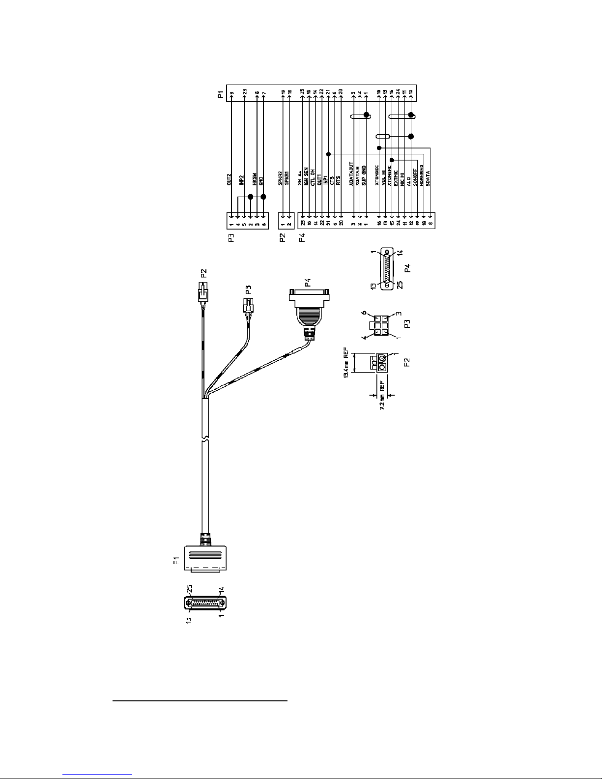
will connect to the Option Connector (OPT) which is mounted on the
back of the Radio Interface Adapter (RIA). See Figure 9.
Figure 9 - Remote Mount Extended Option Accessory Cable
Ignition Sense (All Applications)
(19B802554, Sh.6, Rev. 23)
19B802554P7
17
Page 18

NOTE
NOTE
The radio, as shipped from the factory, has the
"ignition sense" feature disabled. As such the radio
will be powered ON or OFF as determined by the front
panel ON/OFF/VOLUME control only (assuming A+
and A- are connected). If it is desired to enable the
"ignition sense" feature, open the top cover of the radio
and remove the shield from logic PWB. Slide switch
SW601 from position 3-2 to 1-2. Replace shield and
top cover. Be sure to apply correct torque to screws
holding top cover in place. See Maintenance Manual.
The "Accessory" point should drop to ZERO volts
when cranking the engine and return to +12 volts after
the engine is started. If a point is chosen that drops to a
voltage between zero and +12 volts, the radio may
execute a power-up cycle several times during start up.
It is recommended that the terminal be measured with a
voltmeter to be sure it shuts off (goes to zero volts)
during the cranking of the engine.
The fuse holder must be attached to the yellow sense lead along with the
ring terminal as follows:
1. Cut the yellow sense lead approximately 6-12" from the end that will
be connected to the power source.
2. Strip the insulation from each end of the short lead and from the end
of the long lead at least 3/8".
3. Insert the stripped end of the long lead and one end of the short lead
into the narrow end of each fuse holder half.
4. Crimp the leads in the fuse holder halves with a crimping tool.
5. Insert the 3 amp fuse into one end of the fuse holder and join the two
fuse holder halves firmly together.
6. Attach the ring terminal to the end of the short lead and connect this
lead to the ignition "ON" sense point [preferably an "Accessory"
point (in the vehicle fuse panel) that is switched on when the vehicle
ignition switch is in the ACCESSORY and RUN positions].
18
Page 19

CAUTION
Certain problems may be encountered when accessory
equipment is connected to the ignition or accessory
lines of the vehicle, where these lines may have large
filter capacitors and a leakage path present. If the radio
does not turn off within a reasonable amount of time
after the ignition is turned off, first try a different
accessory or ignition sense pick up point in the vehicle.
Many vehicles have more than one circuit that is
switched by the ignition switch, and one may be
available that does not have large filter capacitors or a
leakage path present.
If a different pickup point cannot be found, add a 470ohm, 1-watt resistor from the ignition sense pick point
to ground. This will discharge the capacitor(s) or
reduce the leakage voltage to a low value. Current
drain through this resistor will be minimal (less than
0.03A) when the ignition is switched on.
Control Cable (Remote Mount Only)
The Control Cable is used to connect the Control Unit (through the RIA)
to the Radio Transceiver in remote applications. Plug P2, at one end,
connects to the Remote Control Cable Connector (RCCC) mounted on
the back of the RIA. The Ignition Sense wire is also part of P2. The
connection, P5, is available for field programming, keyloading, or mobile
data applications. The other end of the Control Cable (P1) connects to
the ORCC mounted on the back of the radio. See Figure 10.
CONTROL UNIT MOUNTING
(Remote Applications Only)
1. Using the bracket as a template, mark and drill the mounting holes.
Be sure to leave enough room at the rear of the control unit for the
cable connector. Refer to Figure 11 for control unit mounting bracket
installation.
2. Secure the mounting bracket using the four No. 10 x 3/4 self-tapping
screws supplied (use No. 10 x 1-1/2 if needed.).
3. Secure the control unit to the bracket with the two 1/4-20 x 5/8 hex
head screws and lock washers provided.
19
Page 20

(19B802554, Sh.4, Rev. 23)
Figure 10 – Remote Extended Option Control Cable (CA101288V4)
20
Page 21

Figure 11 – Control Unit Mounting Bracket Installation
SPEAKER
The speaker kit includes the speaker, mounting bracket and connecting
cable. Mount the speaker so it is directed to the operator but does not
present a hazard in the event of an accident. The speaker may be mounted
on the lower edge of the instrument panel, the firewall or above the
windshield in some trucks.
1. Use the mounting bracket as a template for locating the mounting
holes and mount the speaker as shown in Figure 12.
2. Refer to the applicable installation procedures for connection of the
speaker to the accessory cable.
MICROPHONE HANGER AND/OR HOOKSWITCH
MOUNTING
The microphone hanger or hookswitch should be mounted in a location
convenient to the operator where it will not interfere with the safe
operation of the vehicle or be a hazard to the vehicle passengers. The
hanger or hookswitch is designed to be mounted with the open end of the
mounting button slot pointed upward. Use the hanger or hookswitch as a
template to mark and drill the mounting holes. Mount the hanger or
hookswitch with the self-tapping screws provided.
21
Page 22

Figure 12 – Speaker Mounting
SIREN & LIGHT
For instructions about installing the Federal Signal Corporation Siren &
Light Kit, refer to the Federal Signal Corporation Installation Instructions
(Federal Systems part number 255287B, rev. B or higher).
Program the J
AGUAR
725M mobile radio to work with the Federal
Systems Siren & Light Kit, using the instructions outlined in the
ProGrammer On-Line Help.
NOTE: The following issues have been reported on some J
AGUAR
725M
Siren/Light installations using the Federal Signal Corporation Siren &
Light Kit:
• Occasional false activation of siren & light functions when the
ignition is turned to the “on” position and/or when the vehicle is
started.
• Occasional failure to enable siren or light functions via control head,
which can be temporarily resolved by either power cycling the
J
AGUAR
725M radio or turning the car ignition “off” and then “on”
again.
To resolve these issues above, modify the Federal Systems control cable
as follows:
1. Remove the outer shell from the DB25 side of the Federal
Systems control cable.
2. Add a jumper from pin 1 to pin 19.
This modification to the SS2000 cable harness will disable the J
725M capability to turn on and off the SS2000 from the front of the
control head. The SS2000 will now be turned on and off strictly by its
22
AGUAR
Page 23

own ignition switch trigger line (red wire from 12 pin Molex connector
on SS2000 siren box). Follow the SS2000 Federal Signal installation
instructions to attach the red ignition line correctly.
RADIO MOUNTING AND FINAL HOOK-UP
Front Mount
Typically the bracket shown in Figure 13 is used for Front Mount
applications. The bracket can be mounted so that it is either above or
below the radio for the user's convenience. The bracket pictured in
Figure 11 can also be used for Remote Mount applications. The following
instructions are for a Front Mount installation using the bracket shown in
Figure 13.
1. Use the supplied mounting bracket as a template to locate the
position for each of the drill holes. Be sure to leave enough room at
the front and rear of the radio for cable connections. Drill No. 27
(9/64) pilot holes.
2. Mount bracket with four 1/4"-14 x 3/4" sheet metal screws (use 1/4"-
14 x 1-1/2" screws if needed).
3. Place radio into mounting bracket and secure with the four M4 x 10
mm hex head screws, M4 flat washers and M4 lock washers
supplied. No. 20 Torx.
4. Connect antenna coaxial cable to antenna connector (TNC).
5. Connect front mount accessory cable connector P1 to the
Option/Remote Control Connector (ORCC) and secure with the two
captive screws in the connector to the radio.
23
Page 24

Figure 13 – Mounting Bracket Installation
6. Connect front mount accessory cable connector P2 to speaker cable
connector.
7. Connect power cable to power connector on rear of radio unit and
secure with the two captive screws to the radio unit.
8. Connect the microphone connector to the connector on the front
panel and secure with the captive screw.
Do not torque microphone connector screw greater than 2
in-lb. Alternatively, finger tight plus 1/4 turn is acceptable.
NOTE
9. If there are no other accessory connections, tie back plug P3 to main
cable.
10. Recheck all connections before inserting fuse into transmit fuse
assembly.
24
Page 25

Remote Mount Installation
The bracket shown in
Figure 14 is used for Remote Mounting. In some applications the bracket
shown in Figure 13 can also be used for Remote Mounting. The
following instructions are for a Remote Mount installation using the
25
Page 26

bracket shown in
Figure 14.
1. Using the bracket as a template, mark and drill the mounting holes
using a No. 27 drill. Be sure to leave enough room at the rear of the
radio unit for the cable connections.
2. Secure the mounting bracket using four 1/4"-14 x 3/4" sheet metal
screws (use 1/4"-14 x 1" if needed.) The bracket can be used
mounted so that it is either above or below the radio for the user's
convenience.
3. Slide the radio unit into the bracket by aligning bracket guides
with grooves on each side of radio (rear of radio should be inserted first).
Slide radio back until screw holes in front of bracket align with screw
26
Page 27

holes in side of radio. See
Figure 14.
4. Secure radio to the bracket with two M4 x 10 mm socket head screws
provided.
5. Connect antenna coaxial cable to antenna connector (TNC).
6. Connect remote control cable connector P1 to the ORCC connector
on the radio unit and secure with the two captive screws.
7. Connect other end of remote control cable to the remote control
cable connector (RCCC) on the remote control unit.
8. Connect remote mount accessory cable connector P1 to the option
connector (OPT) on control unit. Then connect the speaker to
connector P2 and accessory connector P3 to any options
27
Page 28

(hookswitch, etc.). If connector P3 is not used, insulate and tie back
to main cable.
9. Recheck all connections and cables. Insert fuse into transmit fuse
assembly.
Figure 14 – Remote Mounting Bracket Installation
28
Page 29

DUAL CONTROL UNITS
The Dual Control feature can be configured for either front mount or for
remote mount radio units. Each configuration provides for a Main
Control Unit and an Auxiliary Control Unit. In the front mount
configuration, the Main Control Unit is on the Radio Unit itself (see
xx), with the Auxiliary Control Unit located in a convenient location. In
the remote mount configuration, the Main Control Unit is typically
located in the vehicle cab, with the Auxiliary Control Unit located in a
convenient location (see
All radio units and control units in the Dual Control configuration MUST
BE PROGRAMMED prior to final installation. It is recommended that
the units be first programmed at a Authorized Service Center, then
transferred to the user’s installation.
Fig. xx).
PRE-INSTALLATION PROGRAMMING PROCEDURE
WITH PC PROGRAMMER - FRONT MOUNT
Fig.
The Radio and Control Units must be programmed in a sequential
procedure, in order to provide each Control Unit with the proper
identification code.
1. Configure the J
ProGrammer Assembly, as shown in
radio with the following control configurations:
Network Options
Dual Control Enable
Audio Mode Active
Switching Mode Independent
Siren Light Controller Unit A
Siren Light Connection Unit A
Speaker Disable
Multiple Radio Disable
Program Radio Setup
AGUAR
725M Front Mount Radio with the PC
Figure 31, Step 1. Program the
Mobile Options Push Button
29
Page 30

AGUAR
J
725M Options
Write System Keypad File Enable (System control unit)
Write Scan Keypad File Enable (Scan control unit)
Personality Name <USERPERS> User’s personality file
Radio Code OGXXXXX
Latest radio code file (G13 or
later vintage)
ADI Code <SAME>
Radio Unit ID <SAME>
Keypad File <CUBMAP> Keypad
definition for Control Unit B
CU ID (CU B) Must be Control Unit B
2. Now configure the Front Mount Radio and the Auxiliary Control
Unit together with PC ProGrammer, as shown in
Figure 31, Step 2.
Program this configuration with the following files:
Network Options
Dual Control Enable
Audio Mode Active
Switching Mode Independent
Siren Light Controller Unit A
Siren Light Connection Unit A
Speaker Disable
Multiple Radio Disable
Program Radio Setup
Mobile Options Push Button
J725M Options
Write System Keypad File Enable (System control unit)
Write Scan Keypad File Enable (Scan control unit)
Personality Name <USERPERS> User’s personality file
Radio Code <SAME>
ADI Code <SAME>
Radio ID <SAME>
30
Page 31

Keypad Files<CUAMAP> Keypad definition for
Control Unit A
CU ID CU A Must be Control Unit A
Note that the Main Control Unit has ID “B” and the Auxiliary Control
Unit has ID “A” in this configuration.
Figure 15 - J725M Dual Control Unit PC Programming
Configuration
31
Page 32

PRE-INSTALLATION PROGRAMMING PROCEDURE
WITH PC PROGRAMMER - REMOTE MOUNT
The Radio and Control Units must be programmed in a sequential
procedure, in order to provide each Control Unit with the proper
identification code.
1. Configure the J
AGUAR
ProGrammer Assembly, as shown in
725M Remote Mount Radio with the PC
Figure 32, Step 1. Program the
radio with the following control configurations:
Network Options
Dual Control Enable
Audio Mode Active
Switching Mode Independent
Siren Light Controller Unit A
Siren Light Connection Unit A
Speaker Disable
Multiple Radio Disable
Program Radio Setup
Mobile Options Push Button
J725M Options
Write System Keypad File Enable (System control unit)
Write Scan Keypad File Enable (Scan control unit)
Personality name <USERPERS> User’s personality file
Radio Code OGXXXXX Latest radio code file
(G13 or later vintage)
ADI Code <SAME>
Radio Unit ID <SAME>
Keypad File <CUBMAP> Keypad definition for
Control Unit B
CU ID CU B Must be Control Unit B
2. Now configure the Remote Mount Radio and the Auxiliary Control
Unit together with PC ProGrammer, as shown in
Figure 32, Step 2.
Program this configuration with the following files:
32
Page 33

Network Options
Dual Control Enable
Audio Mode Active
Switching Mode Independent
Siren Light Controller Unit A
Siren Light Connection Unit A
Speaker Disable
Multiple Radio Disable
Program Radio Setup
Mobile Options Push Button
J725M Options
Write System Keypad File Enable (System control unit)
Write Scan Keypad File Enable (Scan control unit)
Personality Name <USERPERS> User’s personality file
Radio Code <SAME>
ADI Code <SAME>
Radio ID <SAME>
Keypad File <CUAMAP> Keypad definition for
Control Unit A
CU ID CU A Must be Control Unit A
Note that the Main Control Unit has ID “A” and Auxiliary Control Unit
has ID “B” in this configuration.
33
Page 34

Figure 16 - J725M Dual Control Unit PC Programming
Configuration Remote Mount
34
Page 35

INSTALLATION INSTRUCTIONS FOR FRONT
MOUNT DUAL CONTROL UNITS
The Dual Control Unit feature is configured such that only one control
unit can be used for Extended Option accessories. All Extended Option
functions are only available at the Main Control Unit.
1. Referring to
between locations for the Radio Unit and Auxiliary Control Unit. Be
sure to locate the P2/P3 connector assembly at the Radio Unit.
2. After installing Radio Unit mounting hardware in the normal fashion,
connect the Dual Control Cable connector (P3) to the Radio Unit.
Tighten the two jackscrews on P3. Next, connect the Accessory
Cable (CA101288V2) Connector (P1) to the Dual Control Cable
Connector (P2), and tighten the jackscrews on P2. Connect the
power cable, and install Radio Unit in mounting bracket.
3. After installing the Auxiliary Control Unit in the normal fashion,
connect the Dual Control Cable (P1) to Auxiliary Control Unit, and
tighten jackscrews.
4. Connect the Remote Mount Accessory Cable (19B802554P7) to the
Auxiliary Control Unit.
5. A yellow Ignition Sense lead is provided on the Dual Control Cable
and the Front Mount Accessory Cable. If the “Ignition Sense”
feature is enabled on the Radio Unit, it is necessary to connect only
one of the yellow leads provided, whichever is convenient. Tape
back the unused yellow lead (See Page 20 for details).
Figure 33, run the Dual Control Cable (19B802554P9)
6. Install the Speakers in convenient locations near the Radio Unit and
Auxiliary Control Unit.
35
Page 36

Parallel Audio Installation Requirements
In special configurations that require both speakers to operate at the same time
(simultaneous audio), install the speakers for parallel audio operation.
Refer to
Fig xx for the Parallel Audio Setup Installation. Perform the
following steps to install parallel audio speakers:
A. Use the two 8Ω speakers, part number 19A149590P12, in place of
the two 4Ω speakers, part number 19A149590P11.
B. Hardwire each speaker directly (without relays) as shown in
Figure
33.
NOTE
It is very important to use the correct speakers for this application,
wiring 4 ΩΩΩΩ speakers in this configuration may cause damage to the radio.
7. Install a relay (19A149299P1) from the kits supplied at a location
near the leads from each speaker. For mounting, use the #8 X 3/4”
sheetmetal screw and nutplate supplied with each kit.
8. At a convenient point cut one of the wires in each of the 2-wire
speaker cables, spread the leads, and strip the ends. Crimp a 1/4” tab
receptacle to each end.
9. Radio Unit Speaker: Connect the lead nearest the speaker to Pin
87A of the relay. Connect the lead nearest the connector to Pin 30 of
the relay. Connect the connector to the Accessory Cable P2 (Refer to
Figure 33).
10. Auxiliary Control Unit Speaker: Connect the lead nearest the
speaker to Pin 87 of the relay. Connect the lead nearest the connector
to Pin 30 of the relay. Connect the connector to the Accessory Cable
P2 (Refer to
Figure 33).
11. For each relay: Connect a #18 AWG black wire between the relay,
Pin 85 and Accessory Cable P3-1 (labeled “OUT2” on the schematic
diagrams in the service manual). Use a 1/4” tab receptacle on the
relay side and mating Molex connector and pins on the accessory
cable side. Connect the mating Molex connector to the Accessory
Cable P3 when finished (Refer to
Figure 33).
12. For each relay: Connect a #18 AWG red wire to the relay, Pin 86.
Cut to length, and connect to the 1 amp fuse holder supplied. Use
crimp on connectors supplied. Connect the other side of the 1 amp
fuse holder to A+ battery source or vehicle A+ fuse block. Use #18
AWG red wire and ring lug supplied., if needed (See
Figure 33).
36
Page 37

13. Check dual control operation, using operator’s manual as a test
guide. In the PC programming software, make sure the “DUAL
CONTROL SPEAKER is programmed ACTIVE LOW.
Figure 17 - J725M Dual Control Unit Front Mount/Remote Mount
Installation Configuration
INSTALLATION INSTRUCTIONS FOR REMOTE
MOUNT DUAL CONTROL UNITS
1. Referring to Figure 34, run the Remote Control Cable
(CA101288V4) between locations for the Radio Unit and Main
Control Unit.
2. Run the Dual Control Cable (19B802554P9) between locations for
the Radio Unit and Auxiliary Control Unit. Be sure to locate the
P2/P3 connector assembly at the radio unit.
3. After installing the Radio Unit in the normal fashion, connect the
dual control cable connector (P3) to the Radio Unit. Tighten the two
jackscrews on P3. Next, connect the Remote Control Cable
connector (P1) to the Dual Control Cable connector (P2), and tighten
jackscrews on P2.
37
Page 38

4. After installing the Main Control Unit in the normal fashion, connect
the Remote Control Cable (P2) to the Main Control Unit, and tighten
jackscrews.
5. After installing the auxiliary control unit in the normal fashion,
connect the Dual Control Cable (P1) to the Auxiliary Control Unit,
and tighten jackscrews.
6. Connect the Remote Mount Extended Option Accessory Cable
(19B802554P6) to the Auxiliary Control Unit and the Main Control
Unit. Please note: All extended option functions are only
available at the Main Control Unit.
7. A yellow ignition sense lead is provided on each control cable. If the
“Ignition Sense” feature is enabled on the Radio Unit, it is
necessary to connect only one of the yellow leads provided,
whichever is convenient. Tape back the unused yellow lead. See
page 20 for details.
8. Install the speakers in convenient locations near each control unit.
Parallel Audio Installation Requirements
In special configurations that require both speakers to operate at the same
time (simultaneous audio), install the speakers for parallel audio operation.
Refer to
following steps to install parallel audio speakers:
A. Use the two 8Ω speakers, part number 19A149590P12, in place of the
B. Hardwire each speaker directly (without relays) as shown in
It is very important to use the correct speakers for this application,
wiring 4 ΩΩΩΩ speakers in this configuration may cause damage to the
radio.
9. Install a relay (19A149299P1) from the kits supplied at a location
near the leads from each speaker. For mounting use the #8 X 3/4”
sheetmetal screw and nutplate supplied with each kit.
10. At a convenient point cut one of the wires in each of the 2-wire
speaker cables, spread the leads, and strip the ends. (Crimp a 1/4” tab
receptacle to each end.
Fig xx for the Parallel Audio Setup Installation. Perform the
two 4Ω speakers, part number 19A149590P11.
Figure 33.
NOTE
11. Main Control Unit Speaker: Connect the lead nearest the speaker to
Pin 87 of the relay. Connect the lead nearest the connector to Pin 30
38
Page 39

of the relay. Connect connector to the accessory cable P2 (Refer to
Figure 34).
12. Auxiliary Control Unit Speaker: Connect the lead nearest the
speaker to Pin 87A of the relay. Connect the lead nearest the
connector to Pin 30 of the relay. Connect the connector to accessory
cable P2 (Refer to
Figure 34).
13. For Each Relay: Connect a #18 AWG black wire between the relay,
Pin 85 and accessory cable P3-1 (labeled “OUT2” on schematic
diagrams in the service manual). Use a 1/4” tab receptacle on the
relay side and a mating Molex connector and pins on the accessory
cable side. Connect the mating Molex connector to the accessory
cable P3 when finished (Refer to
Figure 34).
14. For Each Relay: Connect one end of a #18 AWG red wire to the
relay, Pin 86. Cut the lead to length, and connect the other end to the
1 amp fuse holder supplied. Use crimp on connectors supplied.
Connect the other side of the 1 amp fuse holder to the A+ battery
source or a vehicle A+ fuse block. Use a #18 AWG red wire and a
ring lug supplied, if needed (Refer to
Figure 34).
15. Check dual control operation, using the operator’s manual as a test
guide. In the PC programming software, make sure the “DUAL
CONTROL SPEAKER” is programmed ACTIVE HIGH.
39
Page 40

Figure 18 - J
AGUAR
725M Dual Control Unit PC Programming
Configuration Remote Mount
40
Page 41

FIELD PROGRAMMING WITH PC PROGRAMMER –
DUAL CONTROL UNITS
Once installed, the J
AGUAR
725M can be programmed through connector
P5 on the various cable assemblies, CA101288V2, V4, and V10.
Please note: Keyloading and Mobile Data functions are also available
through the P5 connector on the cable assemblies mentioned above.
Please follow the applicable instructions in the appropriate manuals for
these applications.
Perform the following procedure for each installation configuration:
Field Programming Procedure for Front Mount Dual Control Units
The Radio and Control Units must be programmed in a sequential
procedure in order to provide each Control Unit with the proper
identification code.
1. Configure the J
AGUAR
Control Unit with the PC ProGrammer Assembly as shown in
725M Front Mount Radio and the Auxiliary
Fig.
Xx, Step 1. Program the radio with the control configurations shown
in Step 1 of “Pre-Installation Programming Procedure with PC
ProGrammer – Front Mount” and adjust as necessary for the specific
application.
2. Now configure the Front Mount Radio and Auxiliary Control Unit
together with the PC ProGrammer as shown in
Fig. Xx, Step 2.
Program the configurations shown in Step 2 of “Pre-Installation
Programming Procedure with PC ProGrammer – Front Mount” and
adjust as necessary for the specific application.
41
Page 42

Figure 19 – J725M Field Programming – Dual Control Unit Front
Mount/Remote Mount Configuration
42
Page 43

Field Programming Procedure for Remote Mount Dual Control
Units
The Radio and Control Units must be programmed in a sequential
procedure in order to provide each Control Unit with the proper
identification code.
1. Configure the J
AGUAR
ProGrammer Assembly as shown in
725M Remote Mount Radio with the PC
Fig. Xx, Step 1 with CU #A
disconnected. Program the radio with the control configurations
shown in Step 1 of “Pre-Installation Programming Procedure with
PC ProGrammer – Remote Mount” and adjust as necessary for the
specific application.
2. Now configure the Remote Mount Radio and Auxiliary Control Unit
together with the PC ProGrammer as shown in
Fig. Xx, Step 2,
reconnecting CU #A. Program the configurations shown in Step 2 of
“Pre-Installation Programming Procedure with PC ProGrammer –
Remote Mount” and adjust as necessary for the specific application.
43
Page 44

Figure 20 - J725M Field Programming – Dual Control Unit Remote
Mount/Remote Mount Configuration
44
Page 45

(19B802554, Sh.7, Rev. 23)
Figure 21 – Remote Mount Dual Control Cable 19B802554P9
45
Page 46

DUAL RADIO UNITS
The Dual Radio feature can be configured either for two remote mount
radio units or one front mount unit and one remote mount unit. In remote
mount configurations the Control Unit is typically located in the vehicle
cab, with the Radio Units located side-by-side in vehicle trunk. In
front/remote mount configurations the front mount unit is located in the
vehicle cab, with the remote mount unit located in a convenient location
nearby. The remote/remote mount configuration is the preferred
installation, since a separate control unit is required to program the remote
unit in a front/remote mount configuration.
The following Dual Radio Unit configurations are not allowed:
1. Any configuration using a DIN cassette mount.
2. Any installation where Extended Options are required from both Radio
Units. Extended Options are supported in one Radio Unit only.
PRE-INSTALLATION PROGRAMMING PROCEDURE
WITH PC PROGRAMMER – DUAL RADIO UNITS
All Radio Units in the Dual Radio configuration MUST BE
PROGRAMMED prior to final installation. It is recommended that the
units be first programmed at an Authorized Service Center, then
transferred to the user's installation.
NOTE
Both the J725M Master and J725M Slave mobiles must be
programmed with the same Group version of Flash code. The Group
version must be G30 or later. Failure to do so may result in inadvertent
lockup states in the dual radio configuration.
These configurations provide for a Master Radio Unit and a Slave Radio
Unit. In the remote/remote mount configuration, the Master Radio Unit is
always the radio most directly connected to the Control Unit. In the
front/remote mount configuration, the Master Radio Unit is always the front
mount radio. Extended Options are allowed only in the Master Radio Unit.
Programming each radio is straightforward, except that one radio is
programmed as a Master, and one as a Slave.
1. Decide which Radio Unit shall be the Master Unit. Configure the radio
for programming as shown in the applicable service section manual.
2. Program the radio with the following control configurations:
46
Page 47

Network Options
Dual Control Disable
Speaker Disable
Multiple Radio Enable
Radio Type Slave or Master
Power Up Volume 5
Mute Time-Out 30.0
Termination Enable
Display Selected for Master radio only
Power Up Enable for Master radio only
Power Up Radio Master for Master radio only
Receive Emergency Enable for Master radio only
Receive Only Enable for Master radio only
MuRPS Disable for Master radio only
Program Radio Setup
Mobile Options Push Button
J725M Options
Write System Keypad File Enable (System control unit)
Write Scan Keypad File Enable (Scan control unit)
INSTALLATION INSTRUCTIONS FOR FRONT/
REMOTE MOUNT DUAL RADIO CONFIGURATION
1. Plan the mounting locations of the two Radio Units. Note that the
maximum cable length allowed between the two radios is two meters.
Referring to Figure 36, run Dual Radio Cable (CA101288V10)
between locations for Master and Slave Radio Units. Be sure to locate
the P2/P3 connector assembly at the Master Radio Unit.
2. After installing Master Radio Unit mounting hardware, connect the
Dual Radio Cable Connector (P3) to the Master Radio Unit. Tighten
the two jackscrews on P3. Next connect the Accessory Cable
(CA101288V2) Connector (P1) to the Dual Radio Cable Connector
(P2), and tighten to jackscrews on P2.
47
Page 48

3. Connect Microphone and Accessories. Refer to Accessory Installation
Manual for proper connection of Accessories.
4. Connect Power Cable and Antenna, then install Master Radio Unit in
mounting bracket.
5. Connect "IGN A+" lead, if option is desired. Be sure internal switch
SW601 is set properly.
details.
6. After installing Slave Radio Unit in its mounting hardware, connect
Dual Radio Cable (P1), and tighten jackscrews. Be sure SW601
setting on Slave Radio Unit is same as for Master Radio Unit. Connect
Power Cable and Antenna to Slave Radio.
7. Check Dual Radio operation, using Operator's Manual as test guide.
Refer to NOTE on Page 20 of this manual for
INSTALLATION INSTRUCTIONS FOR REMOTE/
REMOTE MOUNT DUAL RADIO CONFIGURATION
1. Plan the mounting locations of the two Radio Units. Note that the
maximum cable length allowed between the two radios is two meters.
Referring to
between locations for Master and Slave Radio Units. Be sure to locate
the P2/P3 connector assembly at the Master Radio Unit.
2. After installing Master Radio Unit mounting hardware, connect the
Dual Radio Cable Connector (P3) to the Master Radio Unit. Tighten
the two jackscrews on P3.
3. Next route the Remote Mount Extended Option Control Cable
(CA101288V4) between Control Head and Master Radio locations.
After installing Control Head, connect Remote Control Cable
Connector (P2) to Control Head.
4. Connect "IGN A+" lead, if option is desired. Be sure internal Switch
SW601 on Master Radio is set properly.
manual for details.
5. Connect Accessory Cable (19B802554P7) Connector (P1) to Control
Head.
Figure 37, run Dual Radio Cable (CA101288V10)
Refer to Page 20 of this
6. Connect Microphone and Accessories. Refer to Accessory Installation
Manual for proper connection of Accessories.
7. Now connect Remote Control Cable Connector (P1) to the Dual Radio
Cable Connector (P2), and tighten to jackscrews on P2.
48
Page 49

8. Connect Power Cable, and Antenna, then install Master Radio Unit in
mounting bracket.
9. After installing Slave Radio Unit in its mounting hardware, connect
Dual Radio Cable (P1), and tighten jackscrews. Be sure SW601
setting on Slave Radio Unit is same as for Master Radio Unit. Connect
Power Cable and Antenna to Slave Radio.
10. Check Dual Radio operation, using operator's manual as test guide.
Figure 22 - J725M Dual Radio Front Mount Installation
Configuration
49
Page 50

Figure 23 - J725M Dual Radio Remote Mount Installation
Configuration
Enter Field Programming with PC Programmer – Dual Radio Unit
sections.
Figure 24 – Dual Radio Configuration – Front/Remote Mount
50
(Step 1 – Program the Master Unit)
Page 51

Figure 25 – Dual Radio Configuration – Front/Remote Mount
(Step 2 – Program the Slave Unit)
Figure 26 – Dual Radio Configuration – Remote/Remote Mount
(Step 1 – Program the Master Unit)
51
Page 52

Figure 27 – Dual Radio Configuration – Remote/Remote Mount
(Step 2 – Program the Slave Unit)
52
Page 53

(19B802554, Sh.8, Rev. 23)
Figure 28 – Dual Radio Control Cable (CA101288V10)
53
Page 54

ANTENNA
Installation instructions for the antenna are packaged with the antenna.
The antenna must be installed in accordance with good engineering
practice for optimum results.
Typical Mobile Antenna Installation
A permanent mount-type antenna should be located in the center of the
roof or center of rear deck. Important Note: Rear deck mounting of an
antenna is only applicable when the installation provides at least 20
centimeters (8 inches) between the antenna and occupants of the
vehicle. This distance recommendation is made using a 50% duty
cycle.
See “Safety Training Information” section at the
beginning of this manual for further information
regarding Specific Absorption Rate (SAR) limits of
WARNING
RF radiation absorption set by the FCC.
Try to route the cable away from locations where it will be exposed to
heat, sharp edges or mechanical damage, and where it will be out of the
way of the driver, passengers or vehicles mechanics. Wherever possible,
existing holes in the trunk wall, and the channels above or beneath doors
and window columns should be utilized.
Avoid routing the antenna cable near any electronic modules or along
side any vehicle wiring.
Connect the antenna cable to the TNC on the radio, being careful not to
twist the cable.
Typical Desktop Base Station Antenna Installation
For desktop base station configurations, a typical building roof top/tower
installation may be used.
54
Page 55

Warranty
55
Page 56

M/A-COM
3315 Old Forest Road
Lynchburg, Virginia 24501
1-800-528-7711
(Outside USA, 804-385-2400)
Printed in U.S.A.
 Loading...