

Page 1

Page 2

MACO VQ2 QUAD
PACKING LIST
PART QTY OD SIZE LENGTH DESCRIPTION CHECKLIST
T12P 4 ½” .050” 72” ALUM. TUBING FLATTENED W/HOLE ____
T13P 4 5/8” .050” 72” ALUM. TUBING SLOTTED ONE END ____
T28 1 1 ½” .050” 72” ALUM. TUBING ____
T50P 2 1 3/8” .050 4” ALUM. TUBING ____
P01P 1 ¼” x 5” 5” PLATE ____
W01P 1 7/14 34” COPPER WIRE ____
G06P 1 30” GAMMA MATCH (LONG ONE) ____
S42 1 FEMALE COAX CONNECTOR W/MTG NUT ____
Z09P 2 3” GAMMA STRAPS W/COAX CONNECTOR ____
HARDWARE BAG #1
U02 8 1 ½” PLATED U-BOLTS ____
S02 8 1 ½” PLATED SADDLES ____
N03 16 5/16” LOCK NUTS ____
HARDWARE BAG #2
BE1P 4 BOOM TO ELEMENT MOUNTS ____
W58P 4 5/8” EXTRUDED ALUMINUM CLAMPS ____
N11 13 10-24” SQUARE NUTS ____
S30 4 #12 1” SHEET METAL SCREWS ____
S21 12 10-24” ½” MACHINE SCREWS ____
N26 4 #10 FLAT WASHERS ____
N12 4 #10 LOCK WASHERS ____
F01P 1 ¾” COIL FORM ____
PL10 1 1.187-32 PLASTIC CAP-BLACK W/HOLE ____
Z01P 2 ½” 3” GAMMA STRAPS ____
P11 1 BLACK PLASTIC CAP W/HOLE ____
1 TIP SHEET ____
1 WARRANTY SHEET ____
1 SET OF INSTRUCTIONS ____
WHEN ORDERING PARTS, ALWAYS GIVE PART NUMBER AND DESCRIPTION.
Please note: In an effort to keep the price on Maco Antennas down, we have decided not to clean up all the burrs
and rough edges on the parts. We recommend that you deburr and clean up each part with files, sandpaper, etc. so
that they go together easily. We are aware this needs to be done but have elected not to do it to save you the money
we would have to add to the price of the kit for this service.
Rev: 04/09
Page 3
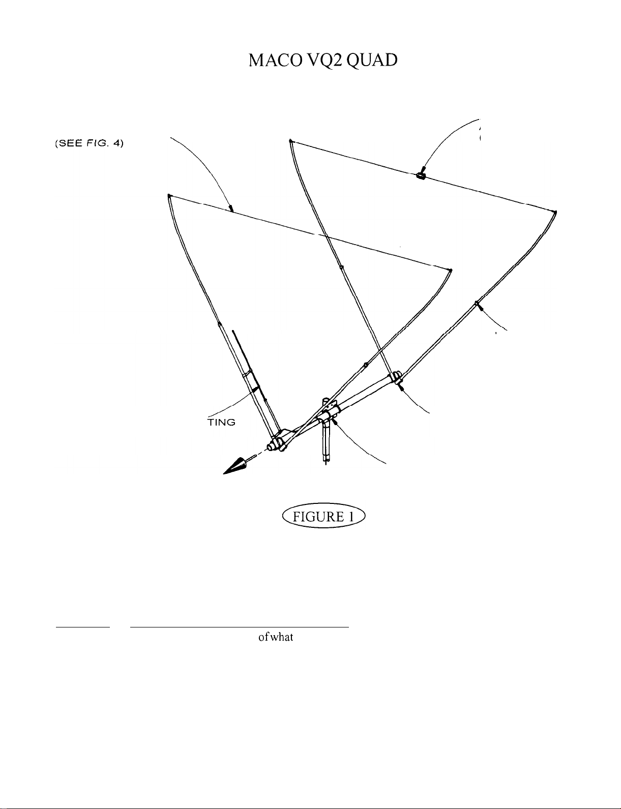
DIRECTOR WIRE ASSEMBLY
REFLECTOR WIRE
ASSEMBLY
(SEE FIG. 5)
ELEMENT ASSEME
(SEE FIG. 3)
ELEMENT-TO-BOOM
GAMMA MATCH MOUN
(SEE FIG. 6)
DIRECTION
RADIATION
FIGURE 1
GENERAL ASSEMBLY INSTRUCTIONS
This figure depicts an overall view
BOOM-TO-MAST MOUNTING
(SEE FIG. 7)
OF
the antenna shouldlook like upon completion of assembly.
MOUNTING
(SEE FIG. 7)
Refer to Figures 2 through 7 for specific assembly details. All hardware should be coated with a silicon rubber
sealant or similar compound to insure that wind vibration does not cause it to work loose.
V QUAD
2
Page 4
I
I
I
I
I
I
I
END OF BOOM
(Figure
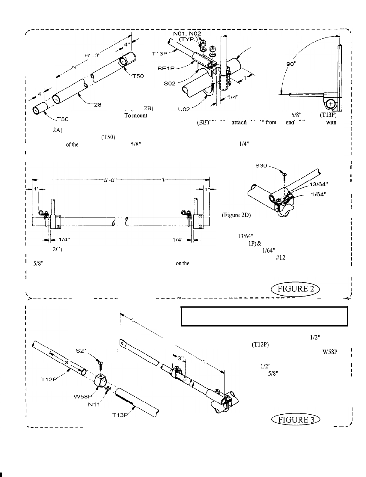
Slide a 4” boom reinforcer
,
mto each end ofthe boom (T28) as
shown.
I (Figure
(Figure
into a boom-to-element mount (Ha
a U-bolt, saddle,, and hardware as shown. Tighten the U-bolt so as to crimp the boom into
an oval shape. This will prevent the element from twisting. Next, fasten a second length
of
tubing to the boom in the same manner,
the first element mount. Tighten as before.
---
Y).
Repeat step 2B on the other end of the boom with the remaining lengths of
tubing. Be sure the elements are lined up with the ones onthe opposite
end of the boom and at a 90 degrees angle. Spacing on each end of the boom
should be shown as above.
tubing
.
. . .
Now
tnis
I
. .
in from, and at a 90 degree angle to
I
I
DRILL I
-1
DRILL
Ifyouliveinahighwindareayoumayfurtherinsure
that your elements will not twist around the boom.
Drill a
dia. hole thru the center of the element
mount (BE saddle (SO2). Using these holes as
a guide, drill a 1
boom and install the
dia. hole thru one side of the
x 1” sheet metal screw
(S3 0). In areas with normal wind conditions this will
not be necessary.
I
I
I
I
I
----
I
ELEMENT-TO-BOOM MOUNTING
--------
i
1 1
‘-9”
Please
read the Assembly and Troubleshooting Tips
end of this instruction booklet before assembling elements.
----
Take the (4) lengths of
and mark each one 3” from
---\
at the
I
tubing
I
the unflattened end. Using a
clamp and hardware shown, insert
the
tubing into the slotted end
of the
tubing to the mark and
tighten clamps. The overall length
I
I
I
I
I
---------------
ELEMENT ASSEMBLY
-__-_---------------------------
3
of each element should be 11’ 9”.
V QUAD
I
I
I
I
I
I
I
Page 5
(OPTIONAL)
7
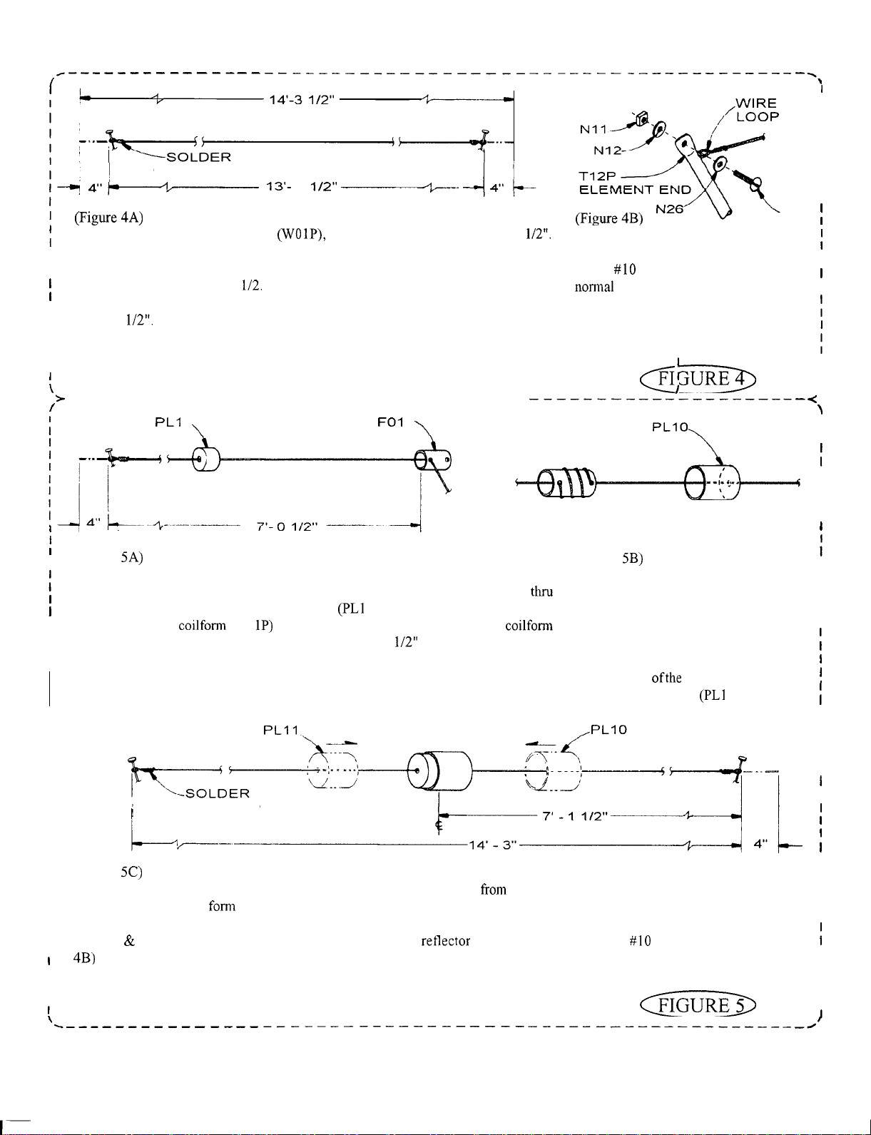
From the 34 ft. roll of copper wire
,
Starting 4” from one end, wrap the wire around a nail or any suitable anchor and twist
I
to form a loop as shown. Making sure that there are no kinks, pull the wire tight and
measure to a length of 13’ 7
this should allow you 4” to form a loop and twist
measure and cut a length of 14’ 3
in the same manner as the opposite end. Check to make sure that your overall length
is 13’ 7
I
I
connection, you may solder the wire twists.
If you desire, in order to insure a stronger and more permanent
I
DIRECT WIRE ASSEMBLY
------- -------------- _____________
s21
Attach the wire between the element
ends on the director end of the boom
using
hardware as shown. It is
each other. This will cause a spring
action and keep any slack out of the
wire.
I
I
I
I
I
I
I
I
,
I
1
(Figure
I
Using the remaining copper wire, start 4” from one end and wrap it around a nail or
suitable anchor and twist to form a loop. Next string the loose end of the wire
the hole in the smaller of the two plastic caps
of the holes in the coilform (FO
I
over the wire to bring its front edge to a distance of 7’
I
I
from inside to out as shown and slid the coilform
P
1). Now string the wire thru one
from the loop end.
(Figure
Wind the wire 3 turns around the
coilfonn, maintaining equal spacing
between the turns and keeping the
coilfonn in its same position on the
wire. String the wire thru the hole in the
other end of the coilfonn. Next string
the loose end ofthe wire thru the hole in
the larger plastic cap
I
I
I
I
I
I
I
I
I
I
I
I
I
(Figure
I
I
Making sure there are no kinks, pull the wire tighten and measure 14’ 3”
I
cut off any excess and
I
the coilfonn is in the center of the wire, and that the overall length is 14’ 3”. Solder your wire twists if desired. Now attach
I
I
the wire
I
I
I
I
(OPTIONAL)
the loop end of the wire. Allowing 4” for wrapping,
a loop in the same manner as the opposite end. Now push the small plastic cap over one end of
coil assembly between the element ends on thee retlector end of the boom using the
REFLECTOR WIRE ASSEMBLY
hardware. (Refer to Fig.
0).
I
I
I
I
I
I
I
I
I
I
I
I
I
I
I
I
I
I
I
I
I
I
I
V QUAD
4
Page 6
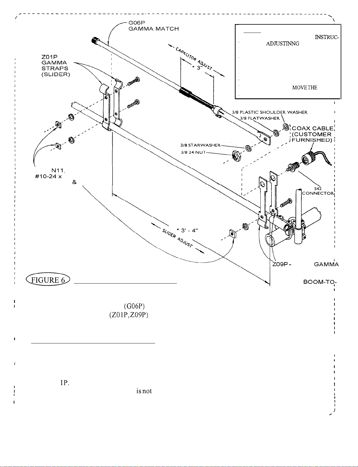
* NOTE:THESE DIMENSONS ARE AP-
PROXIMATE. REFER TO THE
TIONS ON
DETERMINE EXACT SETTINGS. THERE
ARE 2 SEPARATE GAMMA ADJUSTMENTS,
1. CAPACITOR ADJUSTMENT, 2. SLIDER
POSITION.
DO NOT MOVE BOTH AT THE SAME
TIME. MOVE THE CAPACITOR FIRST,
THEN, IFNECESSARY
AND GO BACK TO THE CAPACITOR.
THE S.W.R. TO
SLIDER,
I
I
S21,
LK. WSRS,
I
I
I
I
I
I
I
I
I
I
I
I
I
1) using the Gamma Straps (ZOlP,
to the connector (S42) and dress along boom and down mast.
ADJUSTING STANDING WAVE RATIO
adjustment. Connect a S.W.R. bridge between your transmitter and the antenna and check the S.W.R.
If adjustment is requiredloosen the clamp on the gammamatch and the screws holding the slider (Gamma
Straps ZO
S.W.R. reading is obtained. If S.W.R.
I
readjust the capacitor for a minimum S.W.R. You should now be able to determine which direction to
I
move the slider. Repeat the above procedure, moving the slider in smaller incrementsuntil a satisfactory
\
N12
SCREWS,
SQ. NUTS
- REAR
STRAPS
GAMMA MATCH MOUNTING
(INSTALL FLUSH I
AGAINST
ELEMENT MOUNT)
Attach the Gamma Match (G06P) to the driven element on the director end of the boom (ref. Fig.
and attaching hardware as shown. Attach your coaxial cable
The dimensions given are approximate and should be used as a starting point.*
The Gamma Match has 2 adjustments. First is the capacitor adjustment and second is the slider
Next move the capacitor adjustment first in one direction, then the other until a minimum
satisfactory, move the slider out 2” towards the boom. Now
S.W.R. reading is obtained. Tighten all hardware. Disconnect the S.W.R. bridge and reconnect your
coaxial cable.
5
V QUAD
I
I
I
I
I
I
I
Page 7
112”
02
OF
(CUSTOMER FURNISHED)
BOOM WITH
ATTACHED
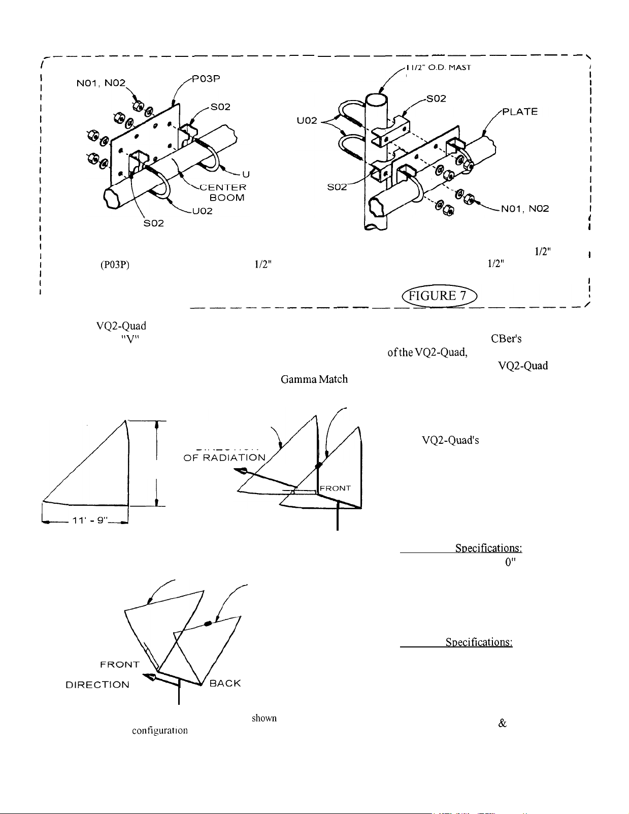
(Figure 7A)
Mark the center of the boom and attach the boom-to-mast
plate
centered on the mark with 1
U-bolts,
saddles and hardware as shown.
(Figure 7B)
this antenna is designed for mounting on a 1
heavy duty mast. Attach using 1
U-bolts, saddles
and hardware as shown.
BOOM-TO-MAST MOUNTING
.----- ---
The VQ2-Quad offers CBer’s the advantages of both horizontal and vertical polarization with only one coax. feed
line. The
annoying fading due to polarization loss can be. With the dual polarity
as much as 20 Db. Both horizontal and vertical polarization is achieved through the VQ2-Quad loop
configuration. Low loss impedance matching GammaMatch assures low S.W.R. for maximum power transfer.
A pretuned reflector resonating coil assures max. F/B ratio.
11'
HORIZONTAL
9"
configuration gives outstanding gain and pin point rejection. Experienced
VQ2-Quad, signal fading is reduced
REFLECTOR
DIRECTOR
DIRECTION
1 I'-9"
VERTICAL
The
structure of top grade aluminum tubing
assures long lasting dependable service.
It handles up to 2000 watts with maximum power transfer.
BACK
know how
rugged mechanical
O.D.
I
I
I
I
For both horizontal and vertical polarization, mount in configuration above.
DIRECTOR
OF RADIATION
REFLECTOR
For horizontal polarization, mount as
here in contiguratlon above.
V QUAD
Mechanical
Boom Length . . . . . . . . . . . 6’
Element Length . . . . . . . . 11’ 9”
Accepts masts up to . ...1.5”
Wind survival . . . . . . . . . . 100 MPH
Net Weight . . . . . . 7.4
lbs.
Electrical Snecifications:
Gain . . . . . . . . . . . 10.5
F/B
Ratio . . . . . . . . . . 25
Side Rejection . . . . . . 40
S.W.R. . . . . . . 1.2
Impedance . . . . . . . . 50
Polarity . . . . . . . .
Db.
Db.
:
1
Ohms
Vertical
Db.
Horizontal
6
Page 8
I
I
10 METER ASSEMBLY INSTRUCTIONS
I
I
I
I
I
I
I
I
I
I
I
I
I
I
I
I
I
I
I
I
I
I
I
I
I
I
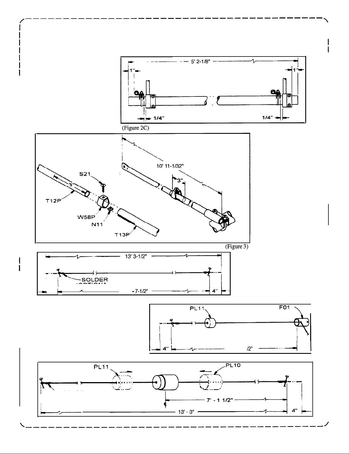
ELEMENT ASSEMBLY
I
I
I
I
I
4”
(Figure 4A)
I
I
(OPTIONAL)
12’
P
I
I
I
I
I
(Figure 5A)
‘-SOLDER
(OPTIONAL)
I
6’ 6-l
I
I
(Figure 5C)
I
I
I
I
I
I
I
I
I
I
I
I
I
I
I
I
I
I
I
I
I
I
I
I
I
I
I
I
I
I
I
I
I
I
I
I
I
I
I
I
I
I
!
7
V QUAD
Page 9

 Loading...