

Page 1

Page 2

MACO M108C
PACKING LIST
PART QTY OD SIZE LENGTH DESCRIPTION CHECKLIST
T01 14 ½” .050” 72” ALUMINUM TUBING ____
T04 2 ½” .050” 80.5” ALUMINUM TUBING ____
T11P 8 5/8” .050” 72” ALUM. TUBING SLOTTED BOTH ENDS ____
T36 1 2.875 .125 48” ALUM TUBING ____
T39 2 3” .060 20’ ALUM TUBING ____
PO4P 1 ¼”x6” 18” PLATE 3” BOOM TO 2” MAST ____
V02P 1 1”x1” 36” VERTICAL GUY SUPPORT W/3 HOLES ____
WD3P 1 6/18 50’ STEEL GUY CABLE ____
G01P 1 GAMMA MATCH ____
Z08P 2 GAMMA STRAPS W/COAX CONNECTOR ____
S42 1 FEMALE COAX CONN. W/MOUNTING NUT ____
HARDWARE BAG #1
S01 5 2” PLATED SADDLES ____
S03 13 3” PLATED SADDLES ____
HARDWARE BAG #2 (DOUBLE BAG)
U01 5 2” PLATED U-BOLTS ____
U03 13 3” PLATED U-BOLTS ____
N03 36 5/16” LOCK NUTS ____
HARDWARE BAG #3
BE3P 8 3” BOOM TO ELEMENT MOUNTS ____
HARDWARE BAG #4
EG2 6 EGG INSULATORS ____
W58P 16 5/8” EXTRUDED ALUMINUM CLAMPS ____
S21 21 10-24 ½” MACHINE SCREWS ____
N11 21 10-24 SQUARE NUTS ____
N12 4 #10 LOCK WASHERS ____
S28 1 ½” 3 ½”” HEX BOLT ____
N15 1 ½” HEX NUT ____
N16 1 ½” LOCKWASHER ____
N17 3 ½” FLAT WASHERS ____
N18 2 5/16” EYEBOLTS-W/ 2 NO1 NUTS EACH ____
PL2 16 .437 PLASTIC CAPS – BLACK ____
PL6 1 3” PLASTIC CAP – BLACK ____
PL6R 1 3” PLASTIC CAP – RED ____
Z02 2 GAMMA STRAPS ____
1 TIP SHEET ____
1 WARRANTY SHEET ____
1 INSTRUCTIONS ____
Please note: In an effort to keep the price on Maco Antennas down, we have decided not to clean up all the
burrs and rough edges on the parts. We recommend that you deburr and clean up each part with files,
sandpaper, etc. so that they go together easily. We are aware this needs to be done but have elected not to
do it to save you the money we would have to add to the price of the kit for this service.
Revised 1/09
Page 3

DIRECTOR
SECOND
DIRECTOR
REFLECTOR
ELEMENT
BLACK PLASTIC
DIRECTOR
THIRD
DIRECTOR
RADIATION
PLASTIC CAP
SIXTH
DIRECTION
OF
RADIATION
63
HORIZONTAL POLARIATION
DRIVEN
SECOND
DIRECTOR
BLACK
PLASTIC
CAP
P-6)
RED PLASTIC
CAP (PLGR)
VERTICAL POLARIATION
FIGURE 1 GENERAL INSTRUCTIONS
This drawing shows a view of the antenna assembled.
The
may be used horizontally or
vertically. These instructions and FIGURES 2 through 4 show the correct assembly instructions. It is highly
recommended that rope be put in the elements to prolong their life. All hardware should be tightened
securely, and then coated with silicon rubber sealant or similar compound to prevent loosening from wind
vibration.
Take care to locate all parts accurately per dimensions given. Complete each step as instructed before
going on to following steps.
Upon completion of assembly, install the red plastic cap (PL6R) on the director end of the antenna,
and the black plastic cap (PL6) on the reflector end. This will allow you to determine at a glance the direction
of transmit and receive.
2
Page 4

3” BOOM
THREAD GUY WIRE THROUGH
EGG INSULATOR AND TWIST END
BOOM
TWIST END OF GUY
HEX NUT
DIRECTOR
BOOM
1” FROM ELEMENT
I I--
NOTE-
THIS CLAMP DOES
NOT ATTACH TO
*Y-F --
OF
END OF GUY
FIGURE 2 BOOM ASSEMBLY
(See figure 2A.) First mark the center of the 2.832” O.D. boom coupler (T35P). Slide both of the
20’ sections of 3” O.D. tubing over the ends of the coupler so they both butt at the coupler center.
(See figure 2B.) Mark the center of the boom to mast plate.
secure with four of the 3” U-bolts (U03) and saddles (S03) and eight of the j/16” lockwashers (N02) and
hex nuts (NOl). Avoid over-tightening the U-bolts as doing so may crush and weaken the boom. Now,
reverse a 3” U-bolt so that it points away from the boom to mast plate. Slide on a 3” saddle, followed by
the vertical guy support, then secure with
From the roll of guy cable (WD3), cut two lengths 2’ long. Take the two eyebolts (N18) and pass
one end of the cable through the eye of the bolt and wrap. Pass the opposite end of the cable through the
hole in the egg insulator
egg insulator is
one nut inside and the other nut on the outside of the vertical guy support. Tighten only finger tight at this
time.
then wrap the cable. Make two of these, then place the eyebolts onto the guy support with
VERTICAL GUY SUPPORT
LOCKWASHERS
HEX NUTS
Center the plate (P04) on the boom and
lockwashers and hex nuts.
and adjust so that the length of cable between the eye of the eyebolt and the
3
Page 5
Please
end of this instruction booklet before assembling elements.
read the Assembly and Troubleshooting Tips
at
the
I
BE3 CLAMP
ELEMENT
NUTS AND
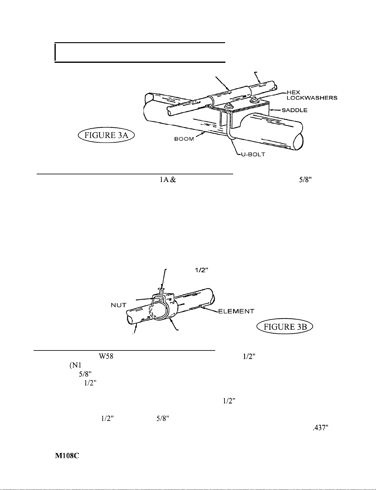
FIGURE 3A ELEMENT CENTER SECTION MOUNTING
Refer to the main sketch (Figures
B) for spacing of the elements. Slide the
x 6’ center
sections inside the boom to element mounts. Mount these onto the boom with 3”” U-bolt assemblies as
shown. Refer to Figure 4 (Gamma Match Assembly) before mounting the driven element and note the
position of the coaxial connector assembly. Space the first saddle 1” from the end of the boom. Again,
be careful not to over-tighten the U-bolts. Line up all the sections after mounting with a level or by any
other accurate means. At this time, refer to Figure 2B and complete the boom guy support system.
Allow 6” of cable for the egg insulator wraps and 16” for the wraps around the boom at the boom
to element mounts. Distances shown should be adhered to plus or minus 1”. Pull the sag out of the boom
by tightening the outside nuts on the guy support, then lock the inside nuts against the guy support.
IO-24 x
IO-24 SQUARE
W58 CLAMP
ELEMENT
MACHINE
SCREW
FIGURE 3B ELEMENT END SECTION MOUNTING
Assemble the
square nuts
position of the
1) only slightly at this time. Refer to Figure 4 (Gamma Match Assembly) and note the
metal clamps that will attach the gamma match to the driven position.
clamps as shown in Figure 2B. Thread the l/2” machine screw (S21) into the
Insert the l/2” O.D. x 72” tubing (no slots) into the driven element and director center sections. Slide
on a W58 clamp assembly over each element and tighten slightly.
Assemble the reflector in the same manner by using the l/2” O.D. x 72” slotted one end sections.
At this time, refer to the element length chart on page 7 and set the element lengths. In setting element
lengths, telescope the
O.D. into the
O.D. by equal amounts. In any case, the minimum length
telescoped into the next larger size should be 3”. Measure overall element lengths, then push the
plastic caps (PL2) over the ends of the premeasured elements.
black
4
Page 6
MOUNTING
I
The
is designed to accept a 2” O.D. mast. A l/4” heavy duty mast designed for this purpose
is recommended. If mounted on a guyed tower, break up the guys every 3’ by using egg insulators in the
guy lines for the top 20’ of the guy cables. Also, the guys should be located at least 12’ below the level of
the boom.
Although it may be desirable to mount the antenna on a mast so that the elements clear the top
of the tower, this should not be attempted unless you are certain that your installation is sturdy enough for
this type of installation.
Experimentation has shown little, if any, effect on the operation of the antenna by
mounting it 2’ above the top of the tower, or by mounting a rotator so that it lies between the vertical elements.
The first consideration should always be the mechanical stability of the antenna.
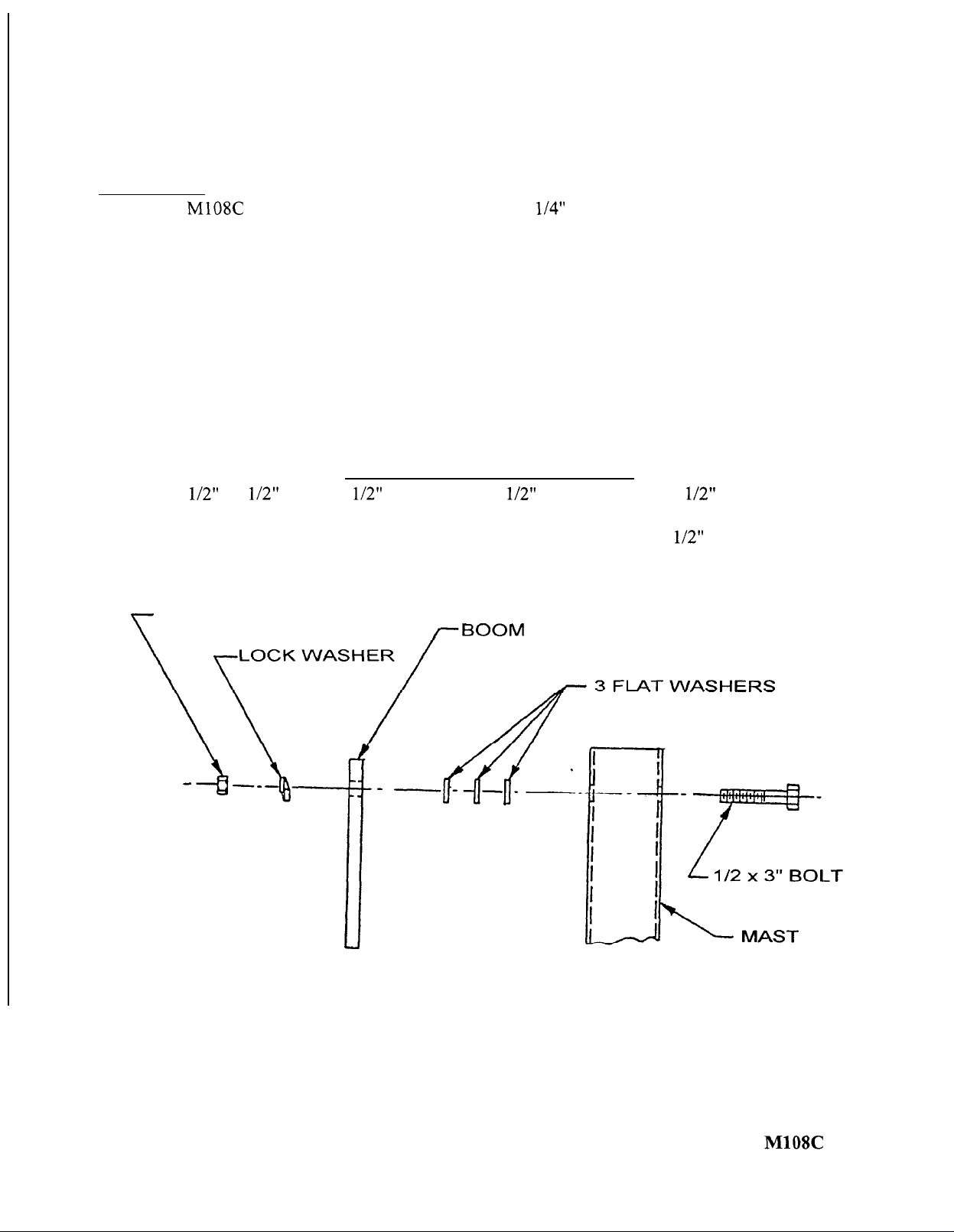
BOOM TO MAST TILT FEATURE
The l/2” x 3 l/2” hex bolt, l/2” lockwasher, (3) l/2” flat washer cut and l/2” hex nut are provided
to give a tilt feature to the boom, if desired.
A hole will have to be drilled through your mast to accommodate the l/2” bolt.
Place the parts as shown below.
NUT
TO
MAST
PLATE
5
Page 7

Page 8

*
THESE DIMENSONS ARE APPROXIMATE.
REFER TO THE INSTRUCTIONS ON ADJUSTINNG THE
S.W.R. TO DETERMINE EXACT SETTINGS. THERE
ARE2 SEPARATEGAMMA ADJUSTMENTS, 1. CAPACITOR ADJUSTMENT, 2. SLIDER POSITION.
DO NOT MOVE BOTH AT THE SAME TIME. MOVE
THE CAPACITOR FIRST, THEN, IF NECESSARY MOVE
THE SLIDER. AND GO BACK TO THE CAPACITOR.
N12-7
LK.
NUTS
GAMMA STRAPS
(SLIDER)
\
DRIVEN
ELEMENT
24 NUT\
STAR-e-(
WASHER
LK. WSHRS & SQ.
I
-
PLASTIC SHOULDER
WASHER
FLATWASHER
GO1 P GAMMA MATCH
N12
x
SCREWS
CABLE
(CUSTOMER
FURNISHED)
FIGURE 4 GAMMA MATCH MOUNTING
Mount the gamma match
to the driven element, using the gamma straps (202,
and attaching
hardware as shown. Attach your 52 ohm coaxial cable to the connector (S42) and dress along boom and down the
mast. The gamma is shown pointing down
this is to let water out.
ADJUSTING THE STANDING WAVE RATIO
Refer to Figure 4. The dimensions given are approximate and should be used as a starting point. * The gamma
match has 2 adjustments. First is the capacitor adjust and second is the slider adjust. Connect a SWR bridge coax
between your transmitter and the antenna and check the SWR. If adjustment is required, loosen the clamp on the
gamma match and the screws holding the slider (gamma straps (202)). Next move the capacitor adjustment first one
direction, then the other until a minimum SWR reading is obtained.
out 2” away from the boom.
If SWR is not yet satisfactory, move the slider
the original position and
towards
the boom. Now readjust the capacitor for minimum SWR. You should now be able to determine which direction to
move the slider. Repeat the above procedure moving the slider in smaller increments until a satisfactory SWR is
obtained. Tighten all hardware. Disconnect the SWR bridge and reconnect your coaxial cable.
NOTE!
When assembling for vertical use, set antenna on a pole about 8 to 9 feet above the ground horizontally and
adjust SWR to 1.7. When you turn the antenna vertical and mount it on the tower, etc., the SWR will drop to 1.4 to
1.5. This is good; QUIT! Antenna results best if vertical antenna clears the top of the tower.
7
Page 9

 Loading...