

Page 1
POSITIVE DISPLACEMENT FLOW METERS
Page 2

ABOUT
MACNAUGHT
Macnaught Pty Ltd is a privately owned manufacturing company based
in Australia, established in 1948. Macnaught’s experience in Positive
Displacement Flow Meter technology extends back to 1964. Macnaught’s
mission is to always exceed industry standards with its products and services.
Macnaught continues to work closely with industry practitioners to
deliver product improvements, new technologies and bespoke solutions.
Macnaught has become a highly sought after manufacturer of precision oval
gear meter technology. This has been achieved through decades of industry
experience and innovation derived from its cutting edge in-house Research
and Development facility with full ISO 9001 and 14001 accreditation.
Macnaught also provide region specific accreditation as required.
Macnaught’s Positive Displacement Flow Meters are suitable for a wide range
of industrial applications including fuel and oil distribution, corrosive chemical
or solvent measurement and high pressure applications to name a few.
Macnaught boasts a network of over 60 international distributors and a
highly skilled global sales support network enabling access to its high
performance and valued products simple, fast and efficient.
Decades of experience have resulted in simple, robust and highly
accurate Positive Displacement Flow Meters. Specify Macnaught Positive
Displacement Flow Meters with confidence for your flow measurement
equipment requirements.
Page 3

CONTENTS
INTRODUCTION 2
RANGE OVERVIEW 2
METER SELECTION GUIDE 4
OPERATING GUIDELINES 7
MXSER IES FLOW METERS 9
MX06 ¼” DIGITAL FLOW METERS SUITABLE FOR FLOW RANGE 0.5100L/HR 12
MX09 ¼” DIGITAL FLOW METERS
MX12 ½” DIG ITAL FLOW METERS
MX19 ¾” DIG ITAL FLOW METERS
MX25 1” DIG ITAL FLOW METERS
MX40 1½” DIG ITAL FLOW METERS
MX50 2” DIGITAL FLOW METERS
MX75 3” DIG ITAL FLOW METERS
MX100 4” DIGITAL FLOW METERS
SUITABLE FOR FLOW RANGE 15500L/ HR 14
SUITABLE FOR FLOW RANGE 230L/ MIN 16
SUITABLE FOR FLOW RANGE 380L/ MIN 18
SUITABLE FOR FLOW RANGE 6120L/MIN 20
SUITABLE FOR FLOW RANGE 10250L/MIN 22
SUITABLE FOR FLOW RANGE 15500L/ MIN 24
SUITABLE FOR FLOW RANGE 20733L/MIN 26
SUITABLE FOR FLOW RANGE 1201200L/MIN 28
MSERIES FLOW METERS 31
M1 ¼” PULSE FLOW METERS
¼” HIGH PRESSURE FLOW METERS
M2 ¼” PULSE FLOW METERS
¼” HIGH PRESSURE FLOW METERS
M4 ½” HIGH PRESSURE FLOW METERS
½” MECHANICAL FLOW METERS
M7 1” PULSE FLOW METERS
1” CUSTODY TRANSFER METERS AU ONLY
M10 1” MECHANICAL FLOW METERS
1” CUSTODY TRANSFER METERS AU ONLY
M40 1½” MECHANICAL FLOW METERS
1½” CUSTODY TRANSFER METERS AU ONLY
M50 2” MECHANICAL FLOW METERS
2” CUSTODY TRANSFER METERS AU ONLY
M80 3” MECHANICAL FLOW METERS
3” CUSTODY TRANSFER METERS AU ONLY
M100 4” MECHANICAL FLOW METERS
4” CUSTODY TRANSFER METERS AU ONLY
SUITABLE FOR FLOW RANGE 0.5100L/HR 40
SUITABLE FOR FLOW RANGE 0.5100L/HR 42
SUITABLE FOR FLOW RANGE 15500L/ HR 44
SUITABLE FOR FLOW RANGE 15500L/ HR 46
SUITABLE FOR FLOW RANGE 230L/ MIN 48
SUITABLE FOR FLOW RANGE 230L/ MIN 50
SUITABLE FOR FLOW RANGE 380L/ MIN 52
SUITABLE FOR FLOW RANGE 1470L/MIN 54
SUITABLE FOR FLOW RANGE 6120L/MIN 56
SUITABLE FOR FLOW RANGE 24120L/MIN 58
SUITABLE FOR FLOW RANGE 10250L/MIN 60
SUITABLE FOR FLOW RANGE 50250L/MIN 62
SUITABLE FOR FLOW RANGE 15500L/ MIN 64
SUITABLE FOR FLOW RANGE 70350L/M IN 66
SUITABLE FOR FLOW RANGE 20733L/MIN 68
SUITABLE FOR FLOW RANGE 140700L/M IN 70
SUITABLE FOR FLOW RANGE 1201200L/MIN 72
SUITABLE FOR FLOW RANGE 2401200L/ MIN 74
ACCESSORIES 77
APPENDICES 86
APPENDIX A FLOW METER ACCURACY AND PRESSURE LOSSES 86
APPENDIX B ACCESSORY DIMENSIONAL DATA 88
APPENDIX C VISCOSITY FACTOR 91
APPENDIX D WARRANTIES & CERTIFICATIONS 92
APPENDIX E CHEMICAL COMPATIBILITY GUIDE 93
macnaught.com.au 1
Page 4

INTRODUCTION
INTRODUCTION
RANGE OVERVIEW
Macnaught’s Positive Displacement Flow Meters are suitable for a wide range of industrial
applications including fuel and oil distribution, corrosive chemical, solvent measurement and high
pressure applications to name a few.
Macnaught offers Positive Displacement Flow Meters featuring Oval Gear technology. The measuring
principle includes two high precision toothed oval gears, which are driven by the flow of the medium and
mesh with each other: in presence of a flow, defined volumes of fluid are transported through the meter
for each rotation of oval gears pair. As the flow rate increases, so does the rotational speed of the rotors.
The number of gear rotations is a measure of the amount of fluid that has passed through the meter;
each rotation is detected by a sensor and the volume is calculated using a conversion factor (K factor).
Figure 1: Macnaught Positive Displacement Flow Meter operation.
A key distinction of positive displacement flow meters is that they offer direct measurement of the
volumetric flow rate. Positive displacement flow meters are frequently specified as they offer high accuracy
and repeatability. They readily provide measurement accuracy within +/-0.5% of the true value.
Additionally, positive displacement flow meters require no power to drive the gear operation with no
special fluid conditioning (e.g. straight lengths of pipe) and are capable of handling high pressure,
large flow variations and plant equipment vibration due to their robust design.
Advantages:
• High accuracy and repeatability
• Suitable for viscous fluids
• Cost-effective
• Accuracy unaffected by changes in viscosity
• Requires minimal maintenance
• Ease of installation
• Exceptional turn-down ratio
Precision engineering and manufacturing methods are used by Macnaught using cutting edge CNC
machining technology and mill certified materials to deliver highly repeatable accuracy and durability.
All critical components are machined in-house with astute quality control monitoring the production
process continuously.*
NOTE: This catalogue is intended to provide general guidance on Macnaught's Positive Displacement Flow Meters. In order to select the most appropriate
meter for your needs, please seek expert advice which is available free-of-charge from Macnaught's Technical Support Team.
2 Macnaught | Positive Displacement Flow Meters
Page 5
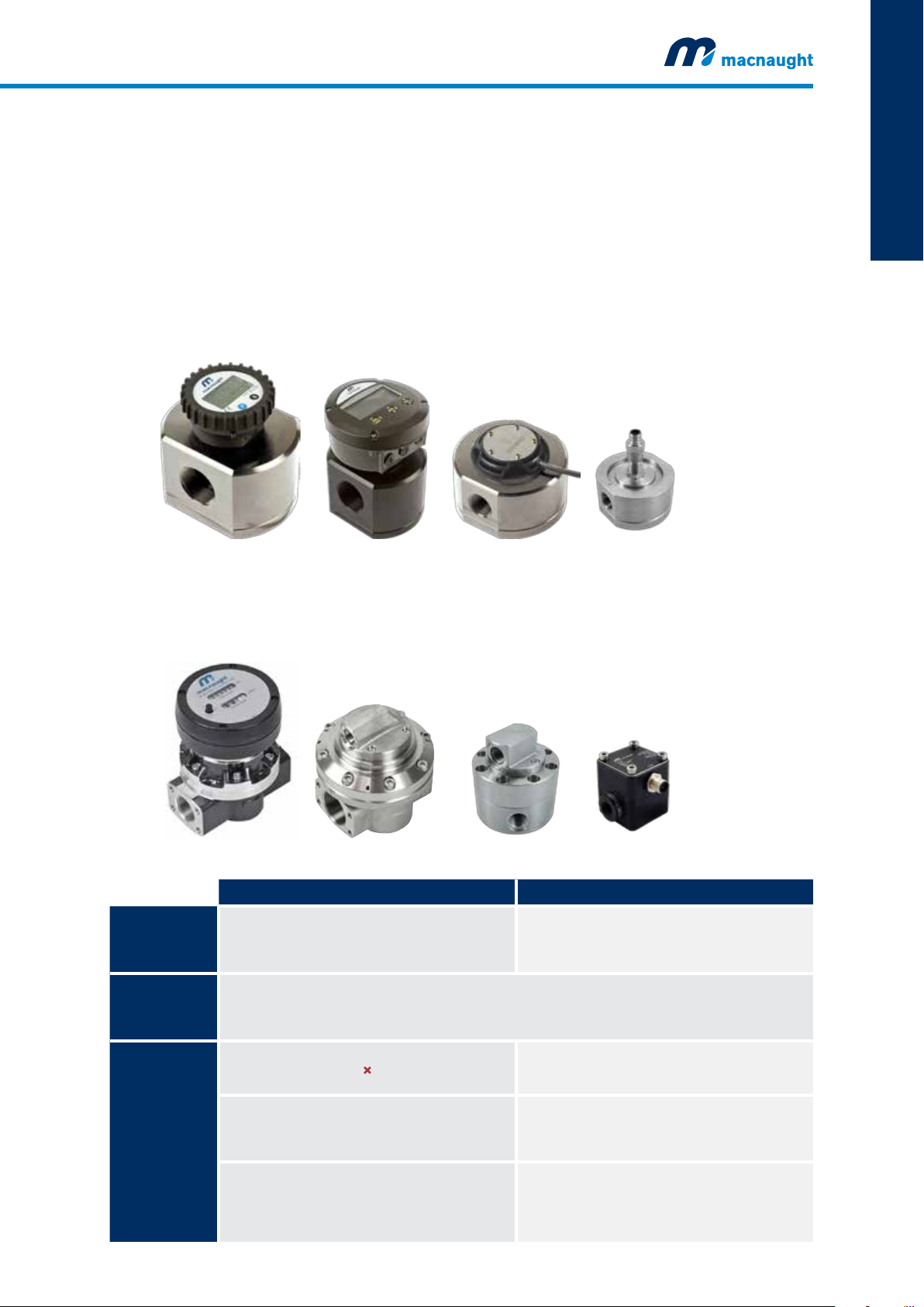
As a result of over 50 years experience with Positive Displacement Flow Meter technology, Macnaught
offers two comprehensive ranges that cater for the ever changing market needs. The latest innovation
with the MX-SERIES range to the original M-SERIES range, Macnaught flow meters are designed
to insist upon durability, reliability and excellence.
The MX-SERIES is the latest innovation featuring:
• High precision billet construction for enhanced material integrity and process reliability
• Programmable digital display and Pulse output options
• Unique bayonet assembly for added versatility and flexibility
INTRODUCTION
The M-SERIES is Macnaught’s original range of meters featuring:
Established design and cast construction for proven performance
Mechanical and pulse output options
Figure 2: Summary of the key features of Macnaught’s Positive Displacement Flow Meters
MXSERIES MSERIES
Billet construction*
Meter Body
Rotor
Output
Mechanical
Output
Electrical
Stainless Steel
Aluminium
PPS (Hastelloy or Stainless Steel)
Aluminium (Carbon Bushing)
316 Stainless Steel (Carbon Bushing)
High Viscosity Rotors (Stainless Steel with Carbon Bushing)
CHECK
Standard Pulse
Intrinsically Safe Pulse
High Temp. Pulseerature Pulse
4 - 20 mA output
Cast construction**
Stainless Steel
Aluminium
PPS
Standard Mechanical Register
Heavy Duty Mechanical Register
Standard Pulse
Digital Display
*Billet construction across the MX meters up to 2”
**M-SERIES all cast with the exception of the MH High Pressure Flow Meters (these are of billet construction)
Full programmable Meter Mount Digital Displays
(PR & ER)
Remote-mountable Digital Displays (PR & ER)
Full programmable Meter Mount Digital Displays
Remote-mount Digital Display
(DR - CR025 only)
(PR & ER)
macnaught.com.au 3
Page 6
INTRODUCTION
INTRODUCTION
METER SELECTION GUIDE
Correct specification of the appropriate meter is necessary to achieve desired accuracy and suitable
data output, as well as to ensure safety in each application. While for most applications, the specification
of the appropriate meter will be straightforward, using the specification process outlined below, for
some applications there may be additional technical considerations which need to be assessed on a
case-by-case basis. In all circumstances we recommend that you consult with Macnaught's Technical
Support Team to select the most appropriate meter for your needs
The following steps are provided as general guidelines to assist with correct meter specification.
However, to ensure accuracy of specification in relation to your application, we recommend seeking
expert advice before making the final selection of the appropriate meter. Please note that Macnaught’s
Technical Support Team is available free-of-charge to assist in the specification and identification of a
suitable meter.
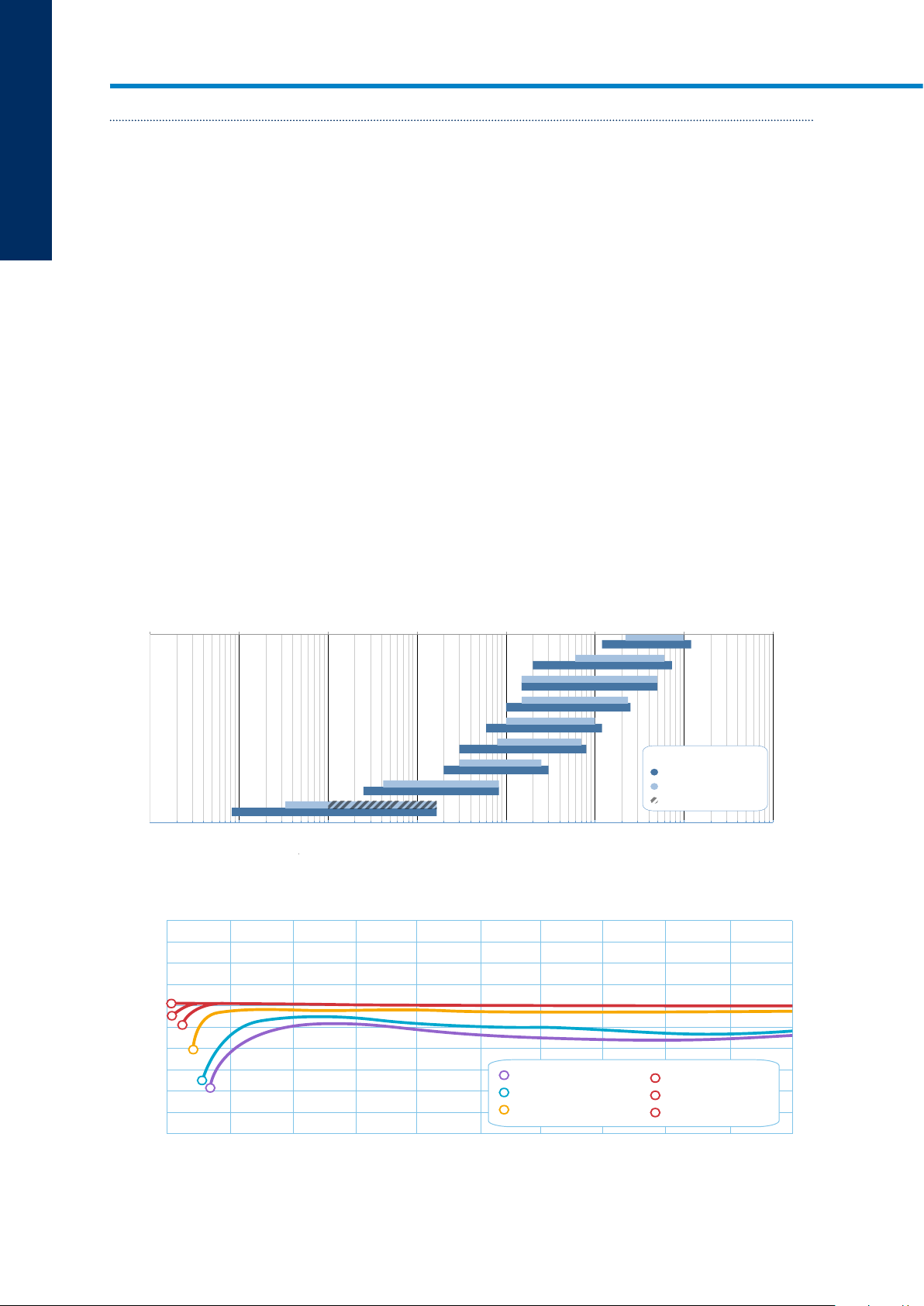
Flow Meter Size
Macnaught Positive Displacement Flow Meters are available in a range of sizes that are engineered
to provide high accuracy across a wide turn down ratio. Figure 3 assists in interpreting your process
flow rate, which is an important determinant to the accuracy of your meter. The size of meter should be
selected for maximum coverage for your operating flow rates. As shown in Figure 4, the accuracy of
the meter is optimal near the mid-range of the meter flow range. In some instances the required flow
rates can fall across two meter options, e.g. if the required flow rate is 3 L/min both the MX09 & the
MX12 are suitable, in such cases it is recommended to select the meter where the flow range is within
the upper 50% of the meter’s flow range limits, i.e. the MX09 is preferred.
Figure 3: Macnaught Positive Displacement Flow Meters flow rate range selection chart
Meter Size Range vs Operating Flowrate
0.001
M100
M80
M50
M40
M10
M-SERIES
M7
M4
M2
M1
0.001 0.01 0.1 10 100 1000
0.01 0.1 1 10 100 1000
Fluid Viscosity Range:
5 - 1000cP
<5cP
<5cP (non lubricating fluids)
1
Operating Flowrate (Q L/min*)
10000
10000
MX100
MX75
MX50
MX40
MX25
MX19
MX12
MX09
MX06
MX-SERIES
Figure 4: Impact of viscosity and flow range on meter accuracy
Accurracy vs Flowrate
+4.0
+3.0
+2.0
+1.0
6
0
5
–1.0
Accuracy %
–2.0
–3.0
–4.0
NOTE: The above graphs are based on generic industry-sourced data. The graphs are intended to be used for illustrative purposes only and may not be
directly applicable to your specific applications. Please seek expert advice from Macnaught's Technical Support Team before final selection.
IMPORTANT: Do not use the above data for product selection.
4 Macnaught | Positive Displacement Flow Meters
4
3
1
2
1
100 20
Gasoline 0.4 cps
2
Water 1
3
Light Oil >20
30
40 50 60 70 80 90 100
Flow as % of maximum capacity
cps
cps
4
A Heavy Oil <20 cps
5
B Heavy Oil 100 cps
6
C Heavy Oil 300 cps
Note:
For viscosities greater than 1000cps
High Viscosity rotors are required
Page 7

Macnaught standard ‘single point’ calibration is carried out at mid-flow range where the individual
K-factor is assigned to the meter.
Identifying the correct meter size for the operating flow rates will ensure the longevity of the meter
and deliver optimal accuracy during its operation. For instances where operation is necessary outside
the designated mid flow range of the meter, it is recommended that an optional ‘multi-point’ calibration
is performed which will help ensure maximum accuracy is achieved. We recommend consulting
Macnaught's Technical Support Team before final selection.
Chemical Compatibility
To determine the most appropriate materials combination for each application it is essential that the
wetted components of the meter assembly are confirmed for chemical compatibility. Macnaught meters
are available in standard materials configurations, as shown on the quick reference table below (figure 5):
common fluid types are listed and the recommended materials combination for each of them is indicated.
For a more comprehensive chemical compatibility guide, please refer to Appendix E on page 93.
The chemical compatibility guides referred to above are intended to provide general guidance on
chemical compatibility. It is highly recommended that the data is checked on a case-by-case basis, as
individual process variations in chemical concentration and temperatures from those of the reference
data can influence compatibility. We advise seeking expert advice from Macnaught’s Technical Support
Team to confirm the materials selection.
INTRODUCTION
Figure 5: Quick reference chemical compatability guide*
BODY
ROTOR
SEALS
Avgas - Jet Fuel
Diesel Fuel
Ethylene Glycol
Gasoline, Unleaded
Kerosene
®
Adblue
Ammonia, anhydrous
Citric Acid
Methyl Ethyl Ketone
Acetone
Ethanol
Hexane
Methanol
Toluene
Phosphoric Acid
Potassium Hydroxide
Sodium Hydroxide
Sulphuric Acid
Water
*Refer to Appendix E - Chemical Compatibility Guide for general guidance on suitability
NOTE: This chart is intended to provide general guidance on chemical compatibility and should not be used for product selection. The chart is based on
industry data and may not be directly applicable to your specific applications. Macnaught does not accept liability for chemical compatibility outside of the
accuracy of the wetted component list. Please consult Macnaught's Technical Support Team before final selection.
PPS AL
SS AL
PPS PPS PPS/SS SS
FFKM FKM FEP FEP
CHECK✓ CHECK✓ CHECK✓ CHECK✓
CHECK✓ CHECK✓ CHECK✓ CHECK✓
CHECK✓ CHECK✓ CHECK✓ CHECK✓
CHECK✓ CHECK✓ CHECK✓ CHECK✓
CHECK✓ CHECK✓ CHECK✓ CHECK✓
CHECK✓
CHECK✓
CHECK✓ CHECK✓ CHECK✓ CHECK✓
CHECK✓
CHECK✓ CHECK✓ CHECK✓ V CHECK✓
CHECK✓ CHECK✓ CHECK✓ V CHECK✓
CHECK✓
CHECK✓
CHECK✓
CHECK✓
CHECK✓
✓
CHECK✓
CHECK✓ V CHECK✓
CHECK✓ CHECK✓
V CHECK✓
CHECK✓
CHECK
CHECK✓
CHECK✓
macnaught.com.au 5
Page 8

Temperature & Pressure Rating
INTRODUCTION
All Macnaught flow meters are designed to be completely safe under normal operating conditions.
However, to ensure user’s safety, it is very important to select a flow meter that will operate within the
process pressure and temperature conditions at all times.
Allowances should be made for any potential ‘spikes’ in pressure (e.g. as a result of sudden valve
closures or as the pump initially starts). If the system pressure is expected to reach the meters maximum
rating it may be necessary to incorporate a pressure relief valve into the system. Macnaught's Technical
Support Team is available to provide advice in this regard.
There are a number of factors that influence the pressure and temperature ratings of a flow meter:
Pressure rating:
• Presence of flanged ports causes a reduction of the pressure rating
• Other modifications to the materials properties
Temperature rating:
• Operational parameters such as the limitations of an attached LCD register and batteries
• Coefficient of expansion or
• Other modifications to the materials properties,
When factors combine, the individual effects could amplify and pose a safety risk. We therefore
recommend seeking expert advice from Macnaught’s Technical Support Team before final selection of
the appropriate meter.
Rotor Type
While Macnaught Positive Displacement Flow Meters are capable of processing a very wide range of
fluid viscosities, the viscosity of fluids still need to be considered to aid the selection process. This value
should always be taken at the applications operating temperature and flow rate. Note that typical fluid
technical data sheets are not usually stated at operating conditions, so further research may be required
to determine this information.
In cases where the fluid is non-Newtonian, additional allowances may be required to compensate for
changes to viscosity between static and dynamic situations.
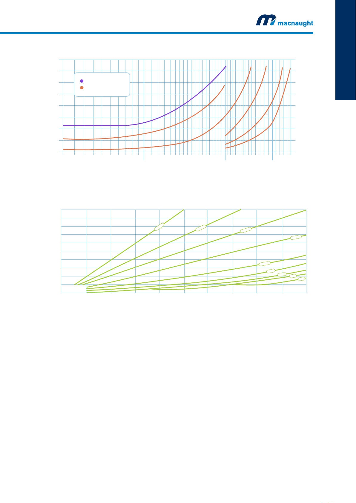
The higher the fluids viscosity the greater the pressure drop it will cause. As shown in Figure 7, the
maximum flow rate will need to be reduced as the viscosity increases. Please contact Macnaught if your
require further assistance. Alternatively, as shown in Figure 6, Macnaught offers High Viscosity (HV)
rotors that have been modified to alleviate this pressure drop and still offer extended flow ranges. As a
general rule if the viscosity is >1000cP it is recommended to use HV rotors, but it is also important to
look for notes on minimum viscosity as this can also affect the meters minimum flow rate.
6 Macnaught | Positive Displacement Flow Meters
Page 9
INTRODUCTION
Figure 6: Benefit of High Viscosity Rotors used to reduce pressure loss impact
Maximum Flow Rate Range
16
INTRODUCTION
110
14
12
Standard Rotors
High Viscosity Rotors
10
%
0
0
8
6
Pressure Loss (psi)
4
1
Flowrate
2
0
0 10,000 1,000,000
Fluid Viscosity (cPs)
Figure 7: Impact of viscosity on pressure loss for a range of flow rates
Pressure drop vs. % flow rate
15.0
13.2
12.0
10.5
9.0
7.5
6.0
Pressure Drop (psi)
4.5
3.0
1.5
6000 cP
100
Flowrate
2000 cP
%
0
5
%
0
0
1
Flowrate
Flowrate
1,000 100,000
1000 cP
97
83
%
%
%
5
2
Flowrate
0
1
Flowrate
5
69
55
Pressure Loss (kPa)
41
28
14
0
300 cP
100 cP
50 cP
10 cP
5 cP
1 cP
100 20
30
40 50 60 70 80 90 100
Flow as % of maximum capacity
Note:
For viscosities greater
than 1000 cPs High
Vi rscosity otors are required
NOTE: The above graphs are based on generic industry-sourced data. The graphs are intended to be used for illustrative purposes only and may not be
directly applicable to your specific applications. Please seek expert advice from Macnaught's Technical Support Team before final selection.
IMPORTANT: Do not use the above data for product selection.
macnaught.com.au 7
Page 10

INTRODUCTION
OPERATING GUIDELINES
While oval gear flow meters provide exceptional accuracy, reliability and a cost effective solution, there
are some considerations for their usage. For example they should not be used to measure fluids with
particles or air pockets in them and adequate filtration needs to be installed upstream of the meter.
Inside the meter are moving components,
so as good practice a routine inspection
may be required. The frequency of the
Figure 8: Recommended installation components for optimal meter operation
OUT
inspection should be based on the
operating conditions; these will include
the maximum flow rate, viscosity and the
fluids lubricating properties. If the meter
FLOWMETER
is used with a lubricating fluid, such as
oil, and is well within the maximum flow
STRAINER
range, then the meter will operate of
many years maintenance free.
IN
Installation Guidelines
1. It is recommended that when setting up pipe work for meter installations a bypass line be
included in the design. This provides the facility for a meter to be removed for maintenance
without interrupting production
2. Use thread sealant on all pipe threads.
3. For pump applications ensure pipe work has the appropriate working pressure rating to match the
pressure output of the pump. Check specified Meter Technical Data section for further details.
4. Install a wire mesh strainer, Y or basket type (refer to pg.82 for Y strainer options) as close as
possible to the inlet side of the meter.
5. For M-series meters ensure that the meter is installed so that the flow of the liquid is in the
direction of the arrows (if applicable) embossed on the meter body.
6. The meter can be installed in any orientation as long as the meter shafts are in a horizontal plane.
(Refer to Figure 9 below for correct installation). The register assembly may be orientated to suit the
individual. Note: Incorrect installation can cause premature wear of meter components.
7. Do not over-tighten meter connections. It is important that after initial installation you fill the line
slowly, high speed air purge could cause damage to the rotors.
8. Test the system for leaks.
9. Check the strainer for swarf or foreign material after the first 1 hour of operation. Check the
strainer for swarf or foreign material periodically, particularly if the flow rate decrease .
Figure 9: Meter orientation for register assembly
✓ ␡✓
8 Macnaught | Positive Displacement Flow Meters
Page 11

MX-SERIES
FLOW METERS
MX-SERIES FLOW METERS
Page 12
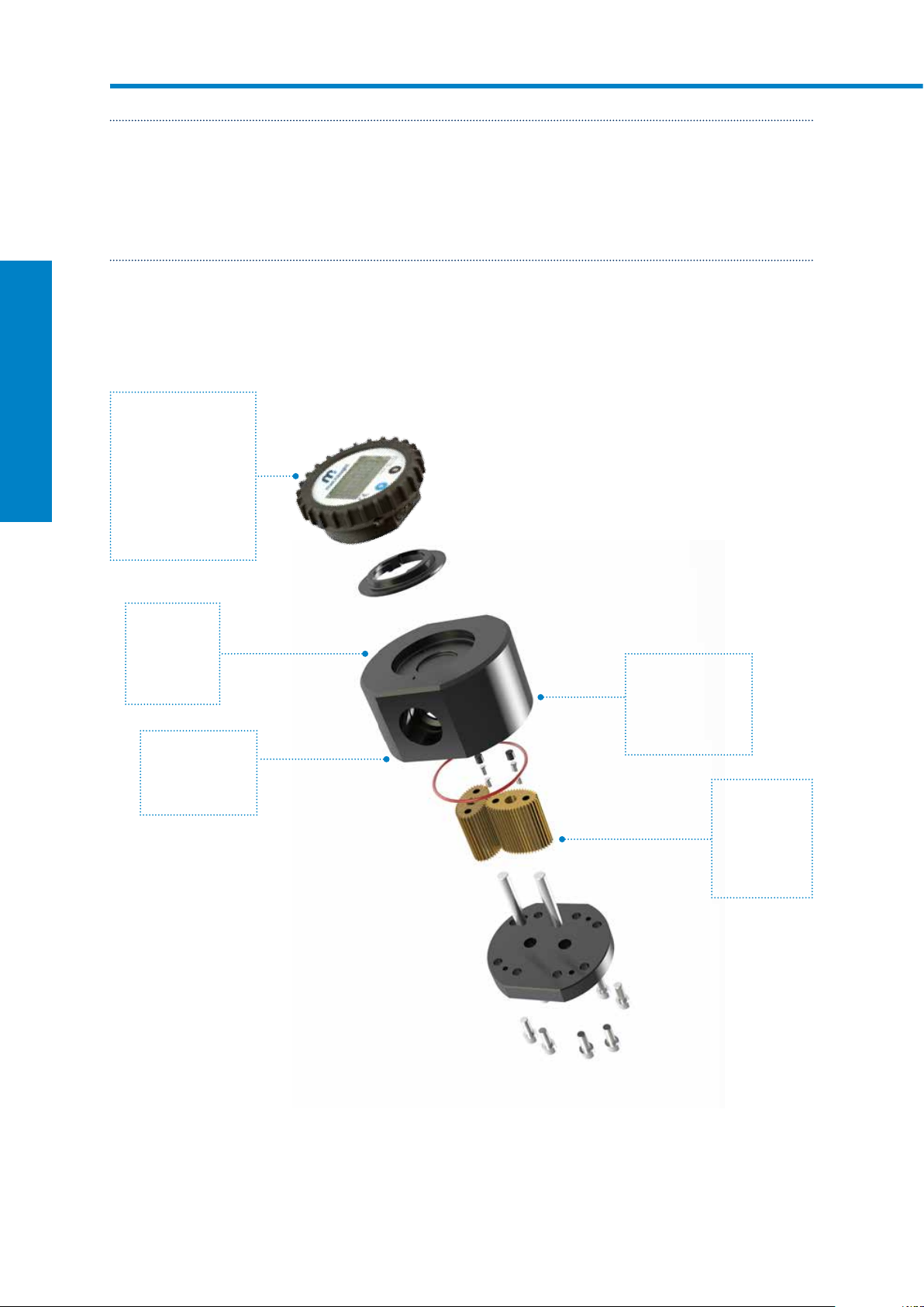
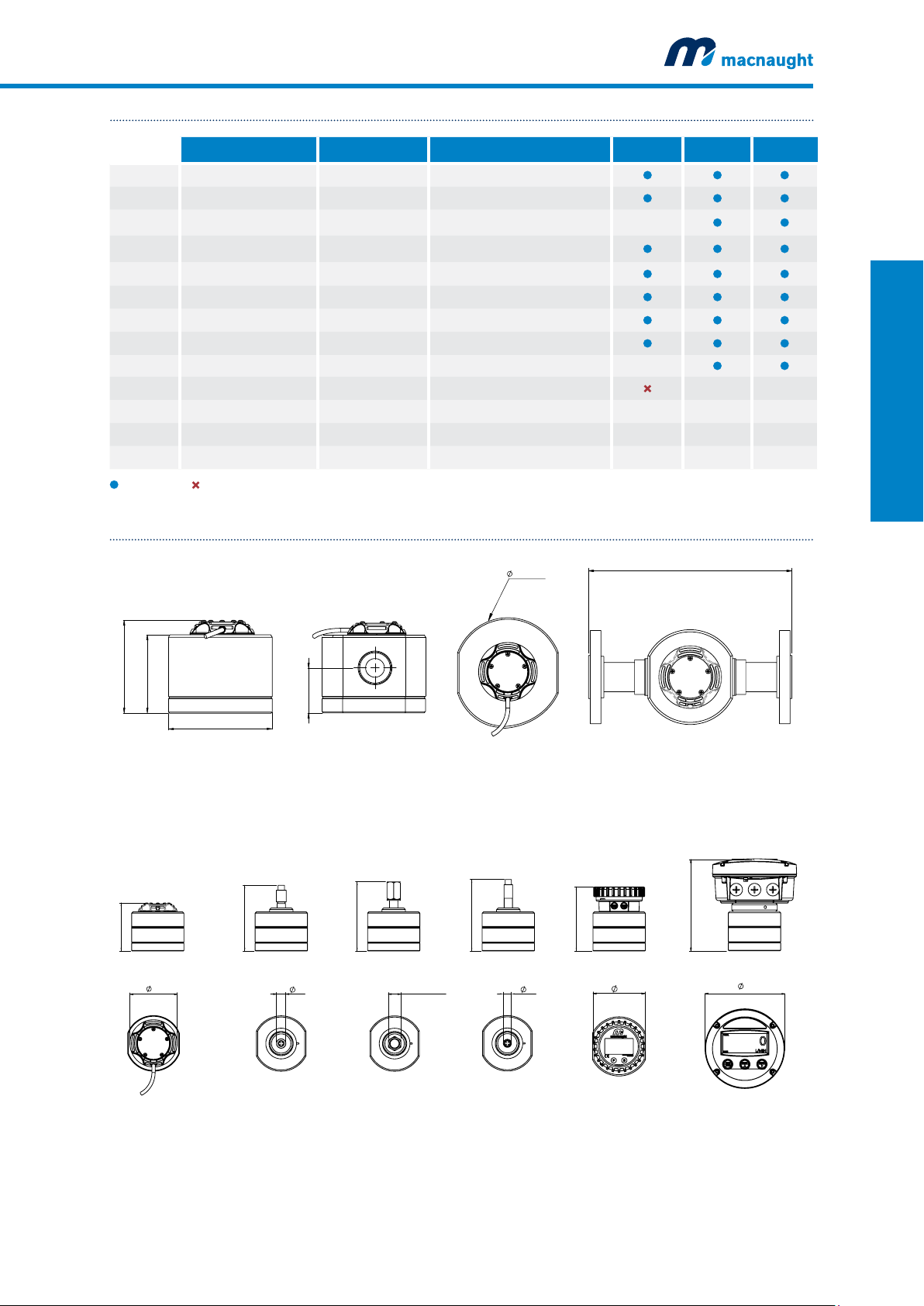
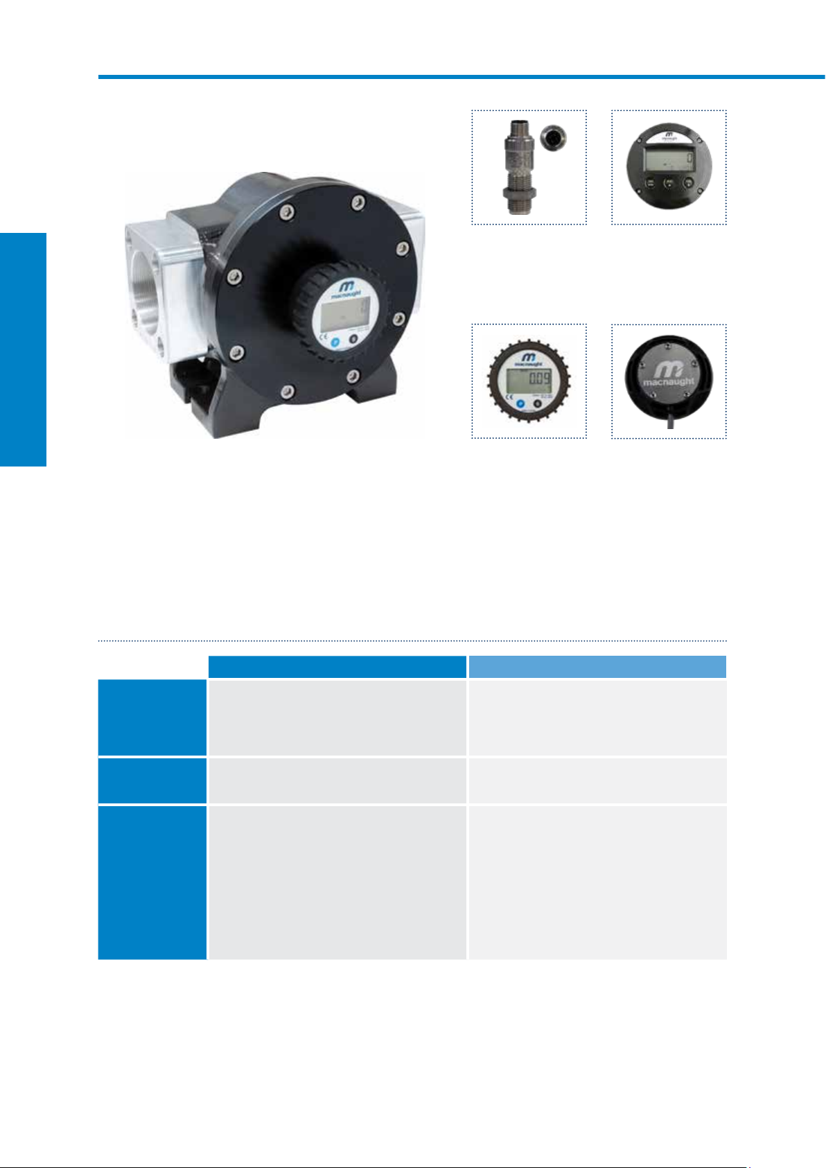
MXSERIES FLOW METERS
DIGITAL FLOW METERS
The Digital Flow Meter range are the latest innovation from Macnaught. They feature billet construction*
offering optimal operational reliability and accuracy. Supplied with an individual Test Report, these meters are
also marked with the actual K factor from calibration testing for an accuracy of +/- 0.5%. Their construction is
modular allowing for simple in situ maintenance and system changes.
EXPLODED DIAGRAM
Output
Macnaught offer
a range of digital
output and display
MX-SERIES FLOW METERS
options that will suit
most applications.
Choose between
display based on
application needs
Port
connection
Based on
desired pipe
connection
Meter size
Choose meter
size based on
flow rate desired
Materials of
construction
Choose material
based on pressure
and fluid type
Rotor type
Select rotor
type based on
the viscosity
of the fluid
and fluid type
*Billet construction across the MX meters up to 2”
10 Macnaught | Positive Displacement Flow Meters
Page 13

PRODUCT IDENTIFICATION SYSTEM
MX06P-1SE
MX06
P
1
MX PORT SIZE
06 09 12 19 25 40 50 75 100
1/4” 1/4” 1/2” 3/4” 1” 1½” 2” 3” 4”
MATERIALS OF CONSTRUCTION
CATEGORY METER/ROTOR/SEAL MODELS
F
P SS/PPS/FEP MX06-50
S
PORT CONNECTION MODEL
1 G
2 NPT
3 ANSI 150
5 DIN PN16
AL/PPS/FKM MX06-50
AL/AL/FKM MX75-100
AL/SS/FEP MX06-25
AL/AL/FEP MX40-100
All Models
MX25-1004 JIS 10K
MX-SERIES FLOW METERS
S
E
ROTOR TYPE MODELS
S Standard As per category
T High Temp. Pulse MX06P - MX50P
V High Viscosity S and P category
OUTPUT TYPE MODELS
X No Output All Models
A Standard Pulse All Models
B Ex approved (Ex ia)
D PR (LCD 12mm display) All Models
E PRA (LCD 12mm display) All Models
F ER (LCD 17mm display) All Models*
G ERA (LCD 17mm display) All Models*
H ERB (LCD 17mm display) All Models*
N Ex Approved (Ex ia NAMUR)
T High Temperature All Models
I Reed/Reed
J Hall/Hall
K High Resolution (omnipolar)
Consult Macnaught Technical
regarding availability
Consult Macnaught Technical
regarding availability
Consult Macnaught Technical
regarding availability
macnaught.com.au 11
Page 14
MX06 ¼” DIGITAL FLOW METERS
SUITABLE FOR FLOW RANGE 0.5100L/HR
MX-SERIES FLOW METERS
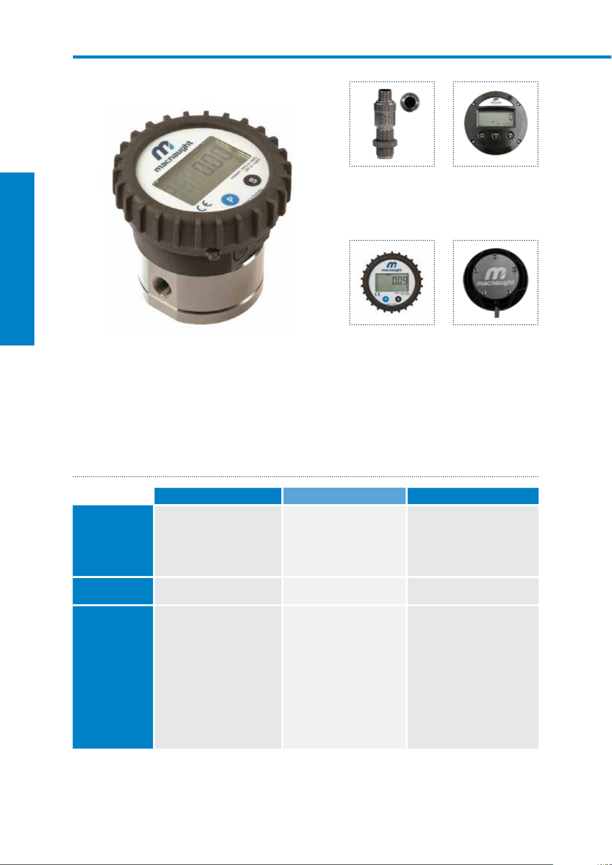
MX06P-1SE
Stainless steel body with LCD register
Output variations:
B - Ex approved (Ex ia)
Intrinsically Safe - NPN
N - Ex approved (Ex ia)
Intrinsically Safe - NAMUR
T - High Temp. Pulse
Max temp- 150ºC
D - PR
LCD Display (12mm)
E - PRA
LCD Display (12mm)
with outputs
F - ER
LCD Display (17mm)
G- ERA
LCD Display (17mm)
H- ERB
LCD Display (17mm)
Batch controller
A - Standard Pulse
Reel/Hall Effect
I - Standard Pulse
Reel/Reed Effect
J - Standard Pulse
Hall/Hall Effect
K - High Resolution
Hall NPN
The MX06 ¼” Digital Flow Meters are suitable for flows between 0.5-100L/hr. The ¼” Digital Flow Meters
have an accuracy of +/- 0.5% and provides exceptional levels of reliability and durability.
SPECIFICATIONS
MX06F MX06S MX06P
Materials of
Construction
Meter Body
Design Specifications
Process Connections ¼” G
Technical
Specifications
Flow rate
Non-lubricating fluids
Operating Temperature
Max. Operating
Pressure
Accuracy
Repeatability
Nominal K-Factor
*Temperature based on standard pulse output - subject to change dependant on rotor and output type, contact Macnaught technical support for further investigations
Rotor
Seals
Range*
Aluminium (6061)
PPS
Fluorocarbon (FKM)
¼” NPT
<5cP
2-100L/hr
0.5-26USG/hr
6-100L/hr
1.58-26USG/hr
-40 - 80ºC
-40 - 176ºF
1000psi
69bar
+/- 0.5%
+/- 0.03%
1000 Pulses/L
>5cP
0.5-100L/hr
0.13-26USG/hr
Aluminium (6061)
Stainless Steel (316)
PTFE Encapsulated (FEP)
¼” G
¼ ” NPT
<5cP
2-100L/hr
0.5-26USG/hr
6-100L/hr
1.58-26USG/hr
-40 - 120ºC
-40 - 248ºF
1000psi
69bar
+/- 0.5%
+/- 0.03%
1000 Pulses/L
>5cP
0.5-100L/hr
0.13-26USG/hr
Stainless Steel (316)
PPS
Stainless Steel (316)
PTFE Encapsulated (FEP)
¼” G
¼” NPT
<5cP
2-100L/hr
0.5-26USG/hr
6-100L/hr
1.58-26USG/hr
-40 - 80ºC (150ºC with high temp. rotors)
-40 - 176ºF (302ºF with high temp. rotors)
1000psi
69bar
+/- 0.5%
+/- 0.03%
1000 Pulses/L
>5cP
0.5-100L/hr
0.13-26USG/hr
12 Macnaught | Positive Displacement Flow Meters
Page 15
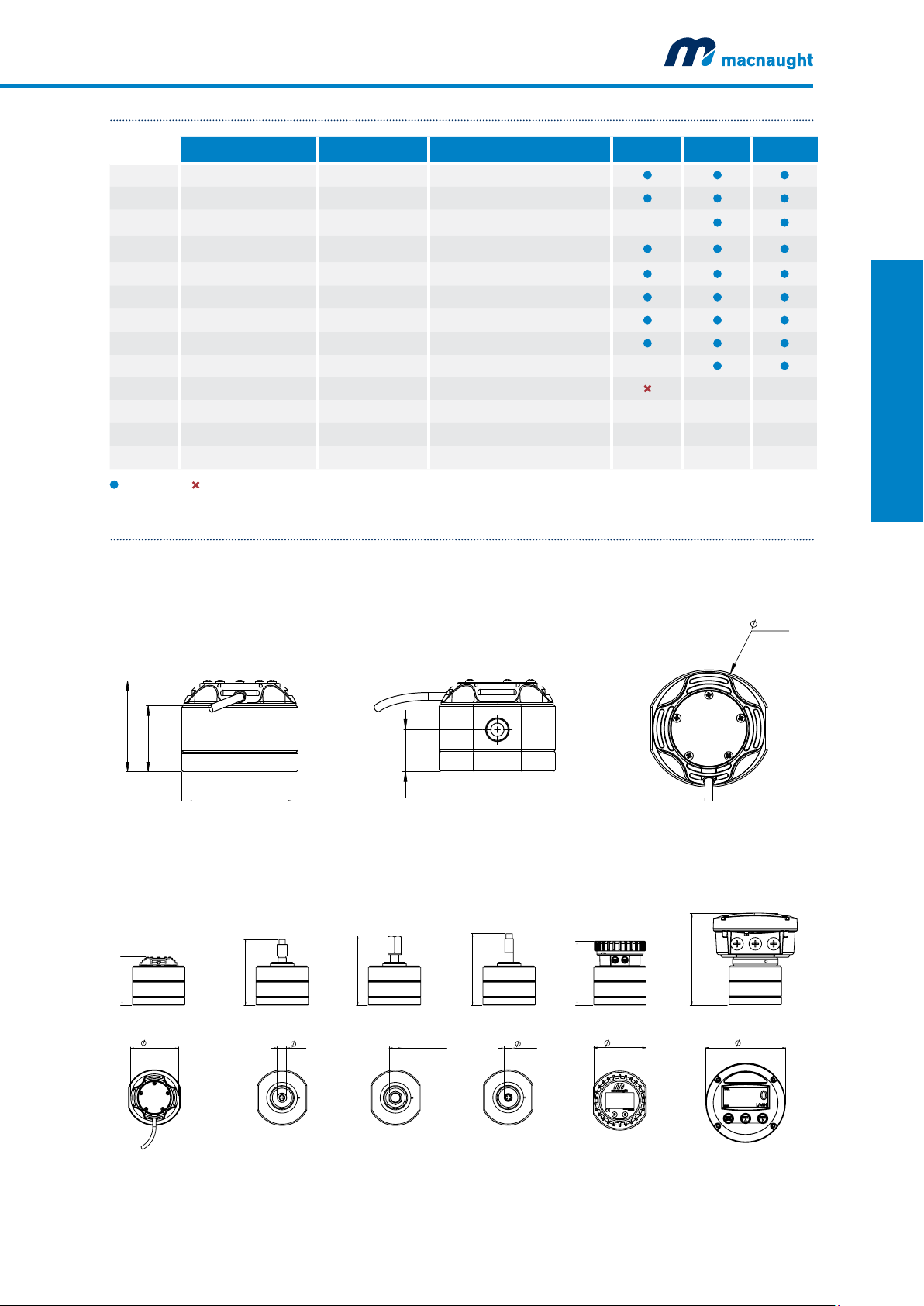
OUTPUTS TYPES
71mm
DESCRIPTION SWITCH TYPE OUTPUT TYPE MX06F MX06S MX06P
X No Output - No Output
A Standard Pulse Reed /Hall (NPN) Pulse (1m flying lead)
B Ex approved (Ex ia) Hall (NPN) Pulse (2m DIN cable) —
D PR (LCD 12mm display) - Display 12mm
E PRA (LCD 12mm display) - Display 12mm, 4-20mA output, Pulse
F ER (LCD 17mm display) - Display 17mm
G ERA (LCD 17mm display) - Display 17mm, 4-20mA output, Pulse
H ERB (LCD 17mm display) - Display 17mm + Batch Control
N Ex Approved (Ex ia NAMUR) NAMUR Pulse (2m DIN cable) —
T High Temp. Pulseerature Hall (NPN) Pulse S S
I Reed/Reed Reed/Reed Pulse (1m flying lead) — — —
J Hall/Hall Hall/Hall Pulse (1m flying lead) — — —
K High Resolution (omnipolar) Hall (NPN) Pulse (1m flying lead) — — —
MX-SERIES FLOW METERS
Available Not Available
DIMENSIONS
A
42mm
OUTPUT A
PULSER - Standard
OUTPUT B
PULSER - Exia
S
Only with stainless steel rotors
25mm
PULSER AND DISPLAY HEIGHT - A
OUTPUT
N
PULSER - Exia
—
Consult Macnaught Technical regarding availability
OUTPUT
T
PULSER - High Temp.
OUTPUT D,E
DISPLAY - LCD 12mm
74mm
OUTPUT
F,G,H
DISPLAY - LCD 17mm
59mm
74mm
93mm
19mm
100mm
25.4mm (1") A/F
104mm
16mm
90mm
99mm
143mm
161mm
macnaught.com.au 13
Page 16
MX09 ¼” DIGITAL FLOW METERS
SUITABLE FOR FLOW RANGE 15500L/HR
MX-SERIES FLOW METERS
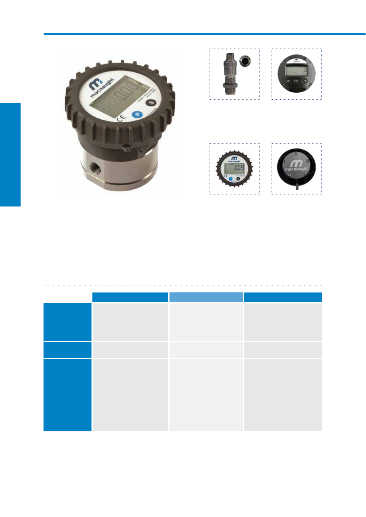
MX09P-1SE
Stainless steel body with LCD register
Output variations:
B - Ex approved (Ex ia)
Intrinsically Safe - NPN
N - Ex approved (Ex ia)
Intrinsically Safe - NAMUR
T - High Temp. Pulse
Max temp- 150ºC
D - PR
LCD Display (12mm)
E - PRA
LCD Display (12mm)
with outputs
F - ER
LCD Display (17mm)
G- ERA
LCD Display (17mm)
H- ERB
LCD Display (17mm)
Batch controller
A - Standard Pulse
Reel/Hall Effect
I - Standard Pulse
Reel/Reed Effect
J - Standard Pulse
Hall/Hall Effect
K - High Resolution
Hall NPN
The MX09 ¼” Digital Flow Meters are suitable for flows between 15-500L/hr. The ¼” Digital Flow Meters have
an accuracy of +/- 0.5% and provides exceptional levels of reliability and durability.
SPECIFICATIONS
MX09F MX09S MX09P
Materials of
Construction
Meter Body
Design Specifications
Process Connections
Technical
Specifications
Flow rate
Operating Temperature
Max. Operating
Pressure
Accuracy
Repeatability
Nominal K-Factor
*Temperature based on standard pulse output - subject to change dependant on rotor and output type, contact Macnaught technical support for further investigations
Rotor
Seals
Range*
Aluminium (6061)
PPS
Fluorocarbon (FKM)
Threaded
¼” G
¼” NPT
<5cP
25-500L/hr
6.6-132USG/hr
-40 - 80ºC
-40 - 176ºF
1000psi
69bar
+/- 0.5%
+/- 0.03%
400 Pulses/L
>5cP
15-500L/hr
4-132USG/hr
Aluminium (6061)
Stainless Steel (316)
PTFE encapsulated (FEP)
Threaded
¼” G
¼” NPT
<5cP
25-500L/hr
6.6-132USG/hr
-40 - 120ºC
-40 - 248ºF
1000psi
69bar
+/- 0.5%
+/- 0.03%
400 Pulses/L
>5cP
15-500L/hr
4-132USG/hr
Stainless Steel (316)
PPS
Stainless Steel (316)
PTFE encapsulated (FEP)
Threaded
¼” G
¼” NPT
<5cP
25-500L/hr
6.6-132USG/hr
-40 - 80ºC (150ºC with high temp. rotors)
-40 - 176ºF (302ºF with high temp. rotors)
1000psi
69bar
+/- 0.5%
+/- 0.03%
400 Pulses/L
>5cP
15-500L/hr
4-132USG/hr
14 Macnaught | Positive Displacement Flow Meters
Page 17

OUTPUTS TYPES
DESCRIPTION SWITCH TYPE OUTPUT TYPE MX09F MX09S MX09P
X No Output - No Output
A Standard Pulse Reed /Hall (NPN) Pulse (1m flying lead)
B Ex approved (Ex ia) Hall (NPN) Pulse (2m DIN cable) —
D PR (LCD 12mm display) - Display 12mm
E PRA (LCD 12mm display) - Display 12mm, 4-20mA output, Pulse
F ER (LCD 17mm display) - Display 17mm
G ERA (LCD 17mm display) - Display 17mm, 4-20mA output, Pulse
H ERB (LCD 17mm display) - Display 17mm + Batch Control
N Ex Approved (Ex ia NAMUR) NAMUR Pulse (2m DIN cable) —
T High Temp. Pulseerature Hall (NPN) Pulse S S
I Reed/Reed Reed/Reed Pulse (1m flying lead) — — —
J Hall/Hall Hall/Hall Pulse (1m flying lead) — — —
K High Resolution (omnipolar) Hall (NPN) Pulse (1m flying lead) — — —
MX-SERIES FLOW METERS
Available Not Available
DIMENSIONS
A
42mm
71mm
OUTPUT A
PULSER - Standard
OUTPUT B
PULSER - Exia
S
Only with stainless steel rotors
25mm
PULSER AND DISPLAY HEIGHT - A
OUTPUT
N
PULSER - Exia
—
Consult Macnaught Technical regarding availability
OUTPUT
T
PULSER - High Temp.
OUTPUT D,E
DISPLAY - LCD 12mm
74mm
OUTPUT
F,G,H
DISPLAY - LCD 17mm
59mm
74mm
93mm
19mm
100mm
25.4mm (1") A/F
104mm
16mm
90mm
99mm
143mm
161mm
macnaught.com.au 15
Page 18
MX12 ½” DIGITAL FLOW METERS
SUITABLE FOR FLOW RANGE 230L/MIN
MX-SERIES FLOW METERS
MX12P-1SE
Stainless steel body with LCD register
Output variations:
B - Ex approved (Ex ia)
Intrinsically Safe - NPN
N - Ex approved (Ex ia)
Intrinsically Safe - NAMUR
T - High Temp. Pulse
Max temp- 150ºC
D - PR
LCD Display (12mm)
E - PRA
LCD Display (12mm)
with outputs
F - ER
LCD Display (17mm)
G- ERA
LCD Display (17mm)
H- ERB
LCD Display (17mm)
Batch controller
A - Standard Pulse
Reel/Hall Effect
I - Standard Pulse
Reel/Reed Effect
J - Standard Pulse
Hall/Hall Effect
K - High Resolution
Hall NPN
The MX12 ½” Digital Flow Meters are suitable for flows between 2-30L/min. The ½” Digital Flow Meters have
an accuracy of +/- 0.5% and provides exceptional levels of reliability and durability.
SPECIFICATIONS
MX12F MX12S MX12P
Materials of
Construction
Meter Body
Design Specifications
Process Connections
Technical
Specifications
Flow rate
Operating Temperature
Max. Operating
Pressure
Accuracy
Repeatability
Nominal K-Factor
*Temperature based on standard pulse output - subject to change dependant on rotor and output type, contact Macnaught technical support for further investigations
Rotor
Seals
Range*
Aluminium (6061)
PPS
Fluorocarbon (FKM)
Threaded
½” G
½” NPT
<5cP
3-25L/min
0.6-6.6USG/min
-40 - 80ºC
-40 - 176ºF
2000 psi
138 Bar
+/- 0.5%
+/- 0.03%
112 Pulses/L
>5cP
2-30L/min
0.5-8USG/min
Aluminium (6061)
Stainless Steel (316)
PTFE encapsulated (FEP)
Threaded
½” G
½” NPT
<5cP
3-25L/min
0.6-6.6USG/min
-40 - 120ºC
-40 - 248ºF
2000 psi
138 Bar
+/- 0.5%
+/- 0.03%
112 Pulses/L
>5cP
2-30L/min
0.5-8USG/min
Stainless Steel (316)
PPS
Stainless Steel (316)
PTFE encapsulated (FEP)
Threaded
½” G
½” NPT
<5cP
3-25L/min
0.6-6.6USG/min
-40 - 80ºC (150ºC with high temp. rotors)
-40 - 176ºF (302ºF with high temp. rotors)
2000 psi
138 Bar
+/- 0.5%
+/- 0.03%
112 Pulses/L
>5cP
2-30L/min
0.5-8USG/min
16 Macnaught | Positive Displacement Flow Meters
Page 19
OUTPUTS TYPES
DESCRIPTION SWITCH TYPE OUTPUT TYPE MX12F MX12S MX12P
X No Output - No Output
A Standard Pulse Reed /Hall (NPN) Pulse (1m flying lead)
B Ex approved (Ex ia) Hall (NPN) Pulse (2m DIN cable) —
D PR (LCD 12mm display) - Display 12mm
E PRA (LCD 12mm display) - Display 12mm, 4-20mA output, Pulse
F ER (LCD 17mm display) - Display 17mm
G ERA (LCD 17mm display) - Display 17mm, 4-20mA output, Pulse
H ERB (LCD 17mm display) - Display 17mm + Batch Control
N Ex Approved (Ex ia NAMUR) NAMUR Pulse (2m DIN cable) —
T High Temp. Pulseerature Hall (NPN) Pulse S S
I Reed/Reed Reed/Reed Pulse (1m flying lead) — — —
J Hall/Hall Hall/Hall Pulse (1m flying lead) — — —
K High Resolution (omnipolar) Hall (NPN) Pulse (1m flying lead) — — —
MX-SERIES FLOW METERS
Available Not Available
DIMENSIONS
A
49mm
OUTPUT A
PULSER - Standard
81mm
OUTPUT B
PULSER - Exia
S
Only with stainless steel rotors
PULSER AND DISPLAY HEIGHT - A
OUTPUT
N
PULSER - Exia
28mm
—
Consult Macnaught Technical regarding availability
OUTPUT
T
PULSER - High Temp.
OUTPUT D,E
DISPLAY - LCD 12mm
87mm
OUTPUT
F,G,H
DISPLAY - LCD 17mm
66mm
74mm
100mm
19mm
107mm
25.4mm (1") A/F
111mm
16mm
97
99mm
150
161mm
macnaught.com.au 17
Page 20
MX19 ¾” DIGITAL FLOW METERS
SUITABLE FOR FLOW RANGE 380L/MIN
MX-SERIES FLOW METERS
MX19P-1SE
Stainless steel body with LCD register
Output variations:
B - Ex approved (Ex ia)
Intrinsically Safe - NPN
N - Ex approved (Ex ia)
Intrinsically Safe - NAMUR
T - High Temp. Pulse
Max temp- 150ºC
D - PR
LCD Display (12mm)
E - PRA
LCD Display (12mm)
with outputs
F - ER
LCD Display (17mm)
G- ERA
LCD Display (17mm)
H- ERB
LCD Display (17mm)
Batch controller
A - Standard Pulse
Reel/Hall Effect
I - Standard Pulse
Reel/Reed Effect
J - Standard Pulse
Hall/Hall Effect
K - High Resolution
Hall NPN
The MX19 ¾” Digital Flow Meters are suitable for flows between 3-80L/min. The ¾” Digital Flow Meters have
an accuracy of +/- 0.5% and provides exceptional levels of reliability and durability.
SPECIFICATIONS
MX19F MX19S MX19P
Materials of
Construction
Meter Body
Design Specifications
Process Connections
Technical
Specifications
Flow rate
Operating Temperature
Max. Operating
Pressure
Accuracy
Repeatability
Nominal K-Factor
*Temperature based on standard pulse output - subject to change dependant on rotor and output type, contact Macnaught technical support for further investigations
Rotor
Seals
Range*
Aluminium (6061)
PPS
Fluorocarbon (FKM)
Threaded
¾” G
¾” NPT
<5cP
8-70L/min
2-18.5USG/min
-40 - 80ºC
-40 - 176ºF
2000 psi
138 Bar
+/- 0.5%
+/- 0.03%
52 Pulses/L
>5cP
3-80L/min
0.8-21USG/min
Aluminium (6061)
Stainless Steel (316)
PTFE encapsulated (FEP)
Threaded
¾” G
¾” NPT
<5cP
8-70L/min
2-18.5USG/min
-40 - 120ºC
-40 - 248ºF
2000 psi
138 Bar
+/- 0.5%
+/- 0.03%
52 Pulses/L
>5cP
3-80L/min
0.8-21USG/min
Stainless Steel (316)
PPS
Stainless Steel (316)
PTFE encapsulated (FEP)
Threaded
¾” G
¾” NPT
<5cP
8-70L/min
2-18.5USG/min
-40 - 80ºC (150ºC with high temp. rotors)
-40 - 176ºF (302ºF with high temp. rotors)
2000 psi
138 Bar
+/- 0.5%
+/- 0.03%
52 Pulses/L
>5cP
3-80L/min
0.8-21USG/min
18 Macnaught | Positive Displacement Flow Meters
Page 21
OUTPUTS TYPES
DESCRIPTION SWITCH TYPE OUTPUT TYPE MX19F MX19S MX19P
X No Output - No Output
A Standard Pulse Reed /Hall (NPN) Pulse (1m flying lead)
B Ex approved (Ex ia) Hall (NPN) Pulse (2m DIN cable) —
D PR (LCD 12mm display) - Display 12mm
E PRA (LCD 12mm display) - Display 12mm, 4-20mA output, Pulse
F ER (LCD 17mm display) - Display 17mm
G ERA (LCD 17mm display) - Display 17mm, 4-20mA output, Pulse
H ERB (LCD 17mm display) - Display 17mm + Batch Control
N Ex Approved (Ex ia NAMUR) NAMUR Pulse (2m DIN cable) —
T High Temp. Pulseerature Hall (NPN) Pulse S S
I Reed/Reed Reed/Reed Pulse (1m flying lead) — — —
J Hall/Hall Hall/Hall Pulse (1m flying lead) — — —
K High Resolution (omnipolar) Hall (NPN) Pulse (1m flying lead) — — —
MX-SERIES FLOW METERS
Available Not Available
DIMENSIONS
A
62mm
100mm
OUTPUT A
PULSER - Standard
OUTPUT B
PULSER - Exia
S
Only with stainless steel rotors
37mm
PULSER AND DISPLAY HEIGHT - A
OUTPUT
N
PULSER - Exia
—
Consult Macnaught Technical regarding availability
OUTPUT
T
PULSER - High Temp.
OUTPUT D,E
DISPLAY - LCD 12mm
112mm
OUTPUT
F,G,H
DISPLAY - LCD 17mm
79mm
74mm
113mm
19mm
120mm
25.4mm (1") A/F
124mm
16mm
110mm
99mm
163mm
161mm
macnaught.com.au 19
Page 22
MX25 1” DIGITAL FLOW METERS
SUITABLE FOR FLOW RANGE 6120L/MIN
MX-SERIES FLOW METERS
MX25P-1SE
Stainless steel body with LCD register
Output variations:
B - Ex approved (Ex ia)
Intrinsically Safe - NPN
N - Ex approved (Ex ia)
Intrinsically Safe - NAMUR
T - High Temp. Pulse
Max temp- 150ºC
D - PR
LCD Display (12mm)
E - PRA
LCD Display (12mm)
with outputs
F - ER
LCD Display (17mm)
G- ERA
LCD Display (17mm)
H- ERB
LCD Display (17mm)
Batch controller
A - Standard Pulse
Reel/Hall Effect
I - Standard Pulse
Reel/Reed Effect
J - Standard Pulse
Hall/Hall Effect
K - High Resolution
Hall NPN
The MX25 1” Digital Flow Meters are suitable for flows between 6-120L/min. The 1” Digital Flow Meters have
an accuracy of +/- 0.5% and provides exceptional levels of reliability and durability.
SPECIFICATIONS
MX25F MX25S MX25P
Materials of
Construction
Meter Body
Design Specifications
Process Connections
Technical
Specifications
Flow rate
Operating Temperature
Max. Operating
Pressure**
Accuracy
Repeatability
Nominal K-Factor
*Temperature based on standard pulse output - subject to change dependant on rotor and output type, contact Macnaught technical support for further investigations
** Pressure rating subject to change as per flange rating
Rotor
Seals
Range*
Aluminium (6061)
PPS
Fluorocarbon (FKM)
Threaded
1” G
1” NPT
<5cP
10-100L/min
2.6-26USG/min
-40 - 80ºC
-40 - 176ºF
2000 psi
138 Bar
+/- 0.5%
+/- 0.03%
36 Pulses/L
Flange
ANSI CLASS 150
DIN PN16
JIS 10k
>5cP
6-120L/min
1.6-32USG/min
Aluminium (6061)
Stainless Steel (316)
PTFE encapsulated (FEP)
Threaded
1” G
1” NPT
<5cP
10-100L/min
2.6-26USG/min
-40 - 120ºC
-40 - 248ºF
2000 psi
138 Bar
+/- 0.5%
+/- 0.03%
36 Pulses/L
Flange
ANSI CLASS 150
DIN PN16
JIS 10k
>5cP
6-120L/min
1.6-32USG/min
Stainless Steel (316)
PPS
Stainless Steel (316)
PTFE encapsulated (FEP)
Threaded
1” G
1” NPT
<5cP
10-100L/min
2.6-26USG/min
-40 - 80ºC (150ºC with high temp. rotors)
-40 - 176ºF (302ºF with high temp. rotors)
2000 psi
138 Bar
+/- 0.5%
+/- 0.03%
36 Pulses/L
Flange
ANSI CLASS 150
DIN PN16
JIS 10k
>5cP
6-120L/min
1.6-32USG/min
20 Macnaught | Positive Displacement Flow Meters
Page 23
OUTPUTS TYPES
DESCRIPTION SWITCH TYPE OUTPUT TYPE MX25F MX25S MX25P
X No Output - No Output
A Standard Pulse Reed /Hall (NPN) Pulse (1m flying lead)
B Ex approved (Ex ia) Hall (NPN) Pulse (2m DIN cable) —
D PR (LCD 12mm display) - Display 12mm
E PRA (LCD 12mm display) - Display 12mm, 4-20mA output, Pulse
F ER (LCD 17mm display) - Display 17mm
G ERA (LCD 17mm display) - Display 17mm, 4-20mA output, Pulse
H ERB (LCD 17mm display) - Display 17mm + Batch Control
N Ex Approved (Ex ia NAMUR) NAMUR Pulse (2m DIN cable) —
T High Temp. Pulseerature Hall (NPN) Pulse S S
I Reed/Reed Reed/Reed Pulse (1m flying lead) — — —
J Hall/Hall Hall/Hall Pulse (1m flying lead) — — —
K High Resolution (omnipolar) Hall (NPN) Pulse (1m flying lead) — — —
MX-SERIES FLOW METERS
Available Not Available
DIMENSIONS
A
75mm
100mm
OUTPUT A
PULSER - Standard
92mm
OUTPUT B
PULSER - Exia
126mm
S
Only with stainless steel rotors
45mm
PULSAR AND DISPLAY HEIGHT - A
OUTPUT
N
PULSER - Exia
133mm
—
Consult Macnaught Technical regarding availability
112mm
OUTPUT
T
PULSER - High Temp.
137mm
OUTPUT D,E
DISPLAY - LCD 12mm
123mm
240mm
176mm
OUTPUT
F,G,H
DISPLAY - LCD 17mm
74mm
19mm
25.4mm (1") A/F
16mm
99mm
161mm
macnaught.com.au 21
Page 24
MX40 1½” DIGITAL FLOW METERS
SUITABLE FOR FLOW RANGE 10250L/MIN
MX-SERIES FLOW METERS
MX40P-1SE
Stainless steel body with LCD register
Output variations:
B - Ex approved (Ex ia)
Intrinsically Safe - NPN
N - Ex approved (Ex ia)
Intrinsically Safe - NAMUR
T - High Temp. Pulse
Max temp- 150ºC
D - PR
LCD Display (12mm)
E - PRA
LCD Display (12mm)
with outputs
F - ER
LCD Display (17mm)
G- ERA
LCD Display (17mm)
H- ERB
LCD Display (17mm)
Batch controller
A - Standard Pulse
Reel/Hall Effect
I - Standard Pulse
Reel/Reed Effect
J - Standard Pulse
Hall/Hall Effect
K - High Resolution
Hall NPN
The MX40 1½” Digital Flow Meters are suitable for flows between 10-250L/min. The 1½” Digital Flow Meters
have an accuracy of +/- 0.5% and provides exceptional levels of reliability and durability.
SPECIFICATIONS
MX40F MX40S MX40P
Materials of
Construction
Meter Body
Design Specifications
Process Connections
Technical
Specifications
Flow rate
Operating Temperature
Max. Operating
Pressure**
Accuracy
Repeatability
Nominal K-Factor
*Temperature based on standard pulse output - subject to change dependant on rotor and output type, contact Macnaught technical support for further investigations
** Pressure rating subject to change as per flange rating
Rotor
Seals
Range*
Aluminium (6061)
PPS
Fluorocarbon (FKM)
Threaded
1½” G
1½” NPT
<5cP
15-235L/min
4-62USG/min
-40 - 80ºC
-40 - 176ºF
1500 psi
103 Bar
+/- 0.5%
+/- 0.03%
14.5 Pulses/L
Flange
ANSI CLASS 150
DIN PN16
JIS 10k
>5cP
10-250L/min
2.6-66USG/min
Aluminium (6061)
Aluminium (6061)
PTFE encapsulated (FEP)
Threaded
1½” G
1½” NPT
<5cP
15-235L/min
4-62USG/min
-40 - 120ºC
-40 - 248ºF
1500 psi
103 Bar
+/- 0.5%
+/- 0.03%
14.5 Pulses/L
Flange
ANSI CLASS 150
DIN PN16
JIS 10k
>5cP
10-250L/min
2.6-66USG/min
Stainless Steel (316)
PPS
Stainless Steel (316)
PTFE encapsulated (FEP)
Threaded
1½” G
1½” NPT
<5cP
15-235L/min
4-62USG/min
-40 - 80ºC (150ºC with high temp. rotors)
-40 - 176ºF (302ºF with high temp. rotors)
1500 psi
103 Bar
+/- 0.5%
+/- 0.03%
14.5 Pulses/L
Flange
ANSI CLASS 150
DIN PN16
JIS 10k
>5cP
10-250L/min
2.6-66USG/min
22 Macnaught | Positive Displacement Flow Meters
Page 25

OUTPUTS TYPES
DESCRIPTION SWITCH TYPE OUTPUT TYPE MX40F MX40S MX40P
X No Output - No Output
A Standard Pulse Reed /Hall (NPN) Pulse (1m flying lead)
B Ex approved (Ex ia) Hall (NPN) Pulse (2m DIN cable) —
D PR (LCD 12mm display) - Display 12mm
E PRA (LCD 12mm display) - Display 12mm, 4-20mA output, Pulse
F ER (LCD 17mm display) - Display 17mm
G ERA (LCD 17mm display) - Display 17mm, 4-20mA output, Pulse
H ERB (LCD 17mm display) - Display 17mm + Batch Control
N Ex Approved (Ex ia NAMUR) NAMUR Pulse (2m DIN cable) —
T High Temp. Pulseerature Hall (NPN) Pulse S S
I Reed/Reed Reed/Reed Pulse (1m flying lead) — — —
J Hall/Hall Hall/Hall Pulse (1m flying lead) — — —
K High Resolution (omnipolar) Hall (NPN) Pulse (1m flying lead) — — —
MX-SERIES FLOW METERS
Available Not Available
DIMENSIONS
A
103mm
120mm
OUTPUT A
PULSER - Standard
120mm
OUTPUT B
PULSER - Exia
154mm
S
Only with stainless steel rotors
61mm
PULSER AND DISPLAY HEIGHT - A
OUTPUT
N
PULSER - Exia
161mm
—
Consult Macnaught Technical regarding availability
137mm
OUTPUT
T
PULSER - High Temp.
165mm
OUTPUT D,E
DISPLAY - LCD 12mm
151mm
240mm
204mm
OUTPUT
F,G,H
DISPLAY - LCD 17mm
74mm
19mm
25.4mm (1") A/F
16mm
99mm
161mm
macnaught.com.au 23
Page 26
MX50 2” DIGITAL FLOW METERS
SUITABLE FOR FLOW RANGE 15500L/MIN
MX-SERIES FLOW METERS
MX50P-1SE
Stainless steel body with LCD register
Output variations:
B - Ex approved (Ex ia)
Intrinsically Safe - NPN
N - Ex approved (Ex ia)
Intrinsically Safe - NAMUR
T - High Temp. Pulse
Max temp- 150ºC
D - PR
LCD Display (12mm)
E - PRA
LCD Display (12mm)
with outputs
F - ER
LCD Display (17mm)
G- ERA
LCD Display (17mm)
H- ERB
LCD Display (17mm)
Batch controller
A - Standard Pulse
Reel/Hall Effect
I - Standard Pulse
Reel/Reed Effect
J - Standard Pulse
Hall/Hall Effect
K - High Resolution
Hall NPN
The MX50 2” Digital Flow Meters are suitable for flows between 15-500L/min. The 2” Digital Flow Meters
have an accuracy of +/- 0.5% and provides exceptional levels of reliability and durability.
SPECIFICATIONS
MX50F MX50S MX50P
Materials of
Construction
Meter Body
Design Specifications
Process Connections
Technical
Specifications
Flow rate
Operating Temperature
Max. Operating
Pressure**
Accuracy
Repeatability
Nominal K-Factor
*Temperature based on standard pulse output - subject to change dependant on rotor and output type, contact Macnaught technical support for further investigations
** Pressure rating subject to change as per flange rating
Rotor
Seals
Range*
Aluminium (6061)
PPS
Fluorocarbon (FKM)
Threaded
2” G
2” NPT
<5cP
15-500L/min
4-130 USG/min
-40 - 80ºC
-40 - 176ºF
1200 psi
82 Bar
+/- 0.5%
+/- 0.03%
6.7 Pulses/L
Flange
ANSI CLASS 150
DIN PN16
JIS 10k
>5cP
15-500L/min
4-130 USG/min
Aluminium (6061)
Aluminium (6061)
PTFE encapsulated (FEP)
Threaded
2” G
2” NPT
<5cP
15-500L/min
4-130 USG/min
-40 - 120ºC
-40 - 248ºF
1200 psi
82 Bar
+/- 0.5%
+/- 0.03%
6.7 Pulses/L
Flange
ANSI CLASS 150
DIN PN16
JIS 10k
>5cP
15-500L/min
4-130 USG/min
Stainless Steel (316)
PPS
Stainless Steel (316)
PTFE encapsulated (FEP)
Threaded
2” G
2” NPT
<5cP
15-500L/min
4-130 USG/min
-40 - 80ºC (150ºC with high temp. rotors)
-40 - 176ºF (302ºF with high temp. rotors)
1200 psi
82 Bar
+/- 0.5%
+/- 0.03%
6.7 Pulses/L
Flange
ANSI CLASS 150
DIN PN16
JIS 10k
>5cP
15-500L/min
4-130 USG/min
24 Macnaught | Positive Displacement Flow Meters
Page 27
OUTPUTS TYPES
DESCRIPTION SWITCH TYPE OUTPUT TYPE MX50F MX50S MX50P
X No Output - No Output
A Standard Pulse Reed /Hall (NPN) Pulse (1m flying lead)
B Ex approved (Ex ia) Hall (NPN) Pulse (2m DIN cable) —
D PR (LCD 12mm display) - Display 12mm
E PRA (LCD 12mm display) - Display 12mm, 4-20mA output, Pulse
F ER (LCD 17mm display) - Display 17mm
G ERA (LCD 17mm display) - Display 17mm, 4-20mA output, Pulse
H ERB (LCD 17mm display) - Display 17mm + Batch Control
N Ex Approved (Ex ia NAMUR) NAMUR Pulse (2m DIN cable) —
T High Temp. Pulseerature Hall (NPN) Pulse S S
I Reed/Reed Reed/Reed Pulse (1m flying lead) — — —
J Hall/Hall Hall/Hall Pulse (1m flying lead) — — —
K High Resolution (omnipolar) Hall (NPN) Pulse (1m flying lead) — — —
MX-SERIES FLOW METERS
Available Not Available
DIMENSIONS
A
124mm
140mm
OUTPUT A
PULSER - Standard
141mm
OUTPUT B
PULSER - Exia
175mm
S
Only with stainless steel rotors
72mm
PULSER AND DISPLAY HEIGHT - A
OUTPUT
N
PULSER - Exia
182mm
—
Consult Macnaught Technical regarding availability
163mm
OUTPUT
T
PULSER - High Temp.
186mm
OUTPUT D,E
DISPLAY - LCD 12mm
172mm
264mm
225mm
OUTPUT
F,G,H
DISPLAY - LCD 17mm
74mm
19mm
25.4mm (1") A/F
16mm
99mm
161mm
macnaught.com.au 25
Page 28
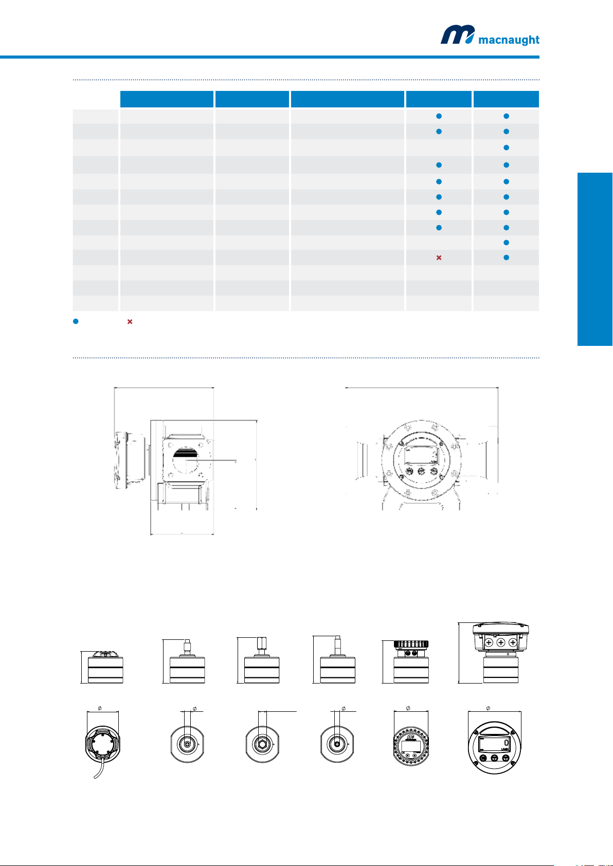
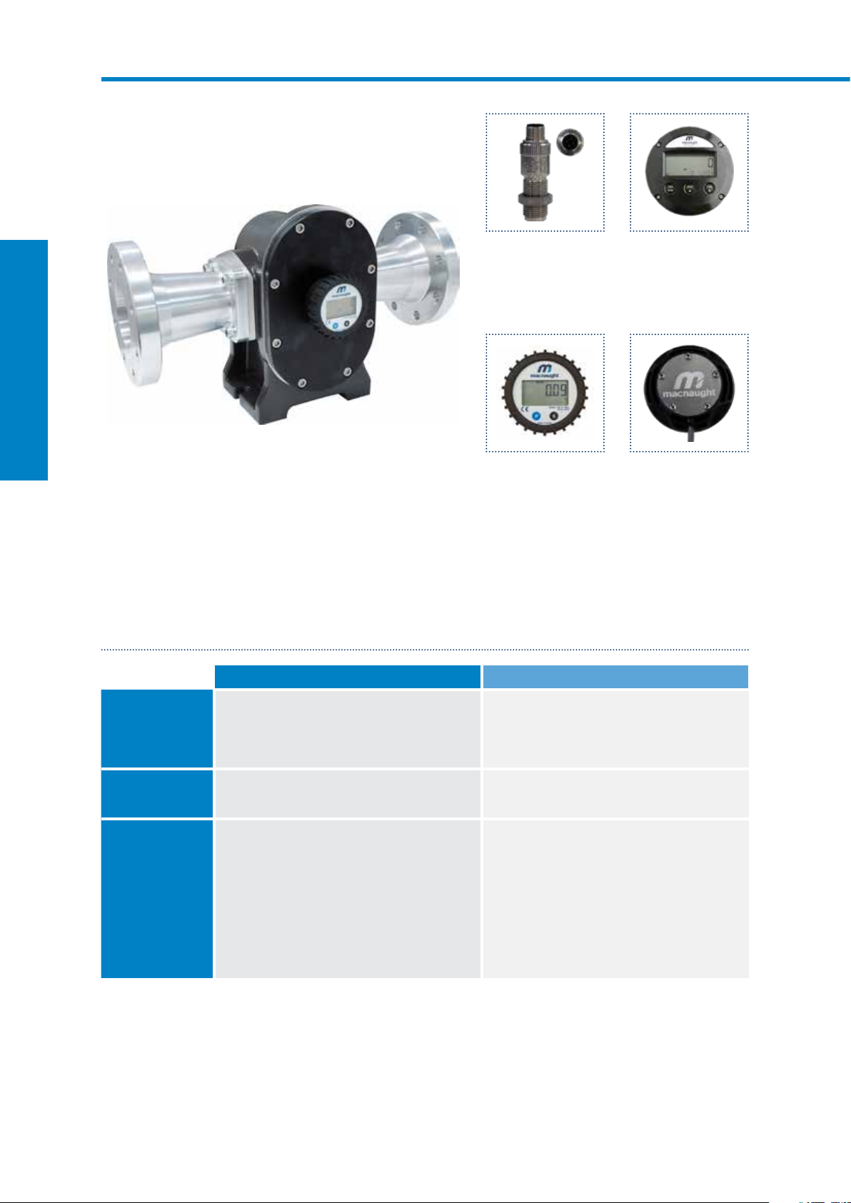
MX75 3” DIGITAL FLOW METERS
SUITABLE FOR FLOW RANGE 20733L/MIN
MX-SERIES FLOW METERS
MX75F-1SE
Aluminium body with LCD register
Output variations:
B - Ex approved (Ex ia)
Intrinsically Safe - NPN
N - Ex approved (Ex ia)
Intrinsically Safe - NAMUR
T - High Temp. Pulse
Max temp- 150ºC
D - PR
LCD Display (12mm)
E - PRA
LCD Display (12mm)
with outputs
F - ER
LCD Display (17mm)
G- ERA
LCD Display (17mm)
H- ERB
LCD Display (17mm)
Batch controller
A - Standard Pulse
Reel/Hall Effect
I - Standard Pulse
Reel/Reed Effect
J - Standard Pulse
Hall/Hall Effect
K - High Resolution
Hall NPN
The MX75 3” Digital Flow Meters are suitable for flows between 20-733L/min. The 3” Digital Flow Meters
have an accuracy of +/- 0.5% and provides exceptional levels of reliability and durability.
SPECIFICATIONS
MX75F MX75S
Materials of
Construction
Meter Body
Design Specifications
Process Connections
Technical
Specifications
Flow rate
Operating Temperature
Max. Operating
Pressure**
Accuracy
Repeatability
Nominal K-Factor
*Temperature based on standard pulse output - subject to change dependant on rotor and output type, contact Macnaught technical support for further investigations
** Pressure rating subject to change as per flange rating
Rotor
Seals
Range*
Cast Aluminium (6061)
Aluminium (6061)
Fluorocarbon (FKM)
Threaded
3” G
3” NPT
<5cP
60-600L/min
17-170USG/min
-40 - 120ºC
-40 - 248ºF
175 psi
12 bar
+/- 0.5%
+/- 0.03%
2.58 Pulses/L
Flange
ANSI CLASS 150
DIN PN16
JIS 10k
>5cP
20-733L/min
5-194USG/min
Cast Aluminium (6061)
Aluminium (6061)
PTFE encapsulated (FEP)
Threaded
3” G
3” NPT
<5cP
60-600L/min
17-170USG/min
-40 - 120ºC
-40 - 248ºF
175 psi
12 bar
+/- 0.5%
+/- 0.03%
2.58 Pulses/L
Flange
ANSI CLASS 150
DIN PN16
JIS 10k
>5cP
20-733L/min
5-194USG/min
26 Macnaught | Positive Displacement Flow Meters
Page 29
OUTPUTS TYPS
436mm*
DESCRIPTION SWITCH TYPE OUTPUT TYPE MX75F MX75S
X No Output - No Output
A Standard Pulse Reed /Hall (NPN) Pulse (1m flying lead)
B Ex approved (Ex ia) Hall (NPN) Pulse (2m DIN cable) —
D PR (LCD 12mm display) - Display 12mm
E PRA (LCD 12mm display) - Display 12mm, 4-20mA output, Pulse
F ER (LCD 17mm display) - Display 17mm
G ERA (LCD 17mm display) - Display 17mm, 4-20mA output, Pulse
H ERB (LCD 17mm display) - Display 17mm + Batch Control
N Ex Approved (Ex ia NAMUR) NAMUR Pulse (2m DIN cable) —
T High Temp. Pulseerature Hall (NPN) Pulse
I Reed/Reed Reed/Reed Pulse (1m flying lead) — —
J Hall/Hall Hall/Hall Pulse (1m flying lead) — —
K High Resolution (omnipolar) Hall (NPN) Pulse (1m flying lead) — —
MX-SERIES FLOW METERS
Available Not Available
DIMENSIONS
OUTPUT A
PULSER - Standard
A
179mm
OUTPUT B
PULSER - Exia
S
Only with stainless steel rotors
254mm
141mm
PULSER AND DISPLAY HEIGHT - A
OUTPUT
N
PULSER - Exia
—
Consult Macnaught Technical regarding availability
436mm*
OUTPUT
T
PULSER - High Temp.
OUTPUT D,E
DISPLAY - LCD 12mm
OUTPUT
F,G,H
DISPLAY - LCD 17mm
196mm
74mm
230mm
19mm
237mm
25.4mm (1") A/F
241mm
*Length subject to change refer to appendix B (pg. 88) for full dimension variations
16mm
227mm
99mm
280mm
161mm
macnaught.com.au 27
Page 30
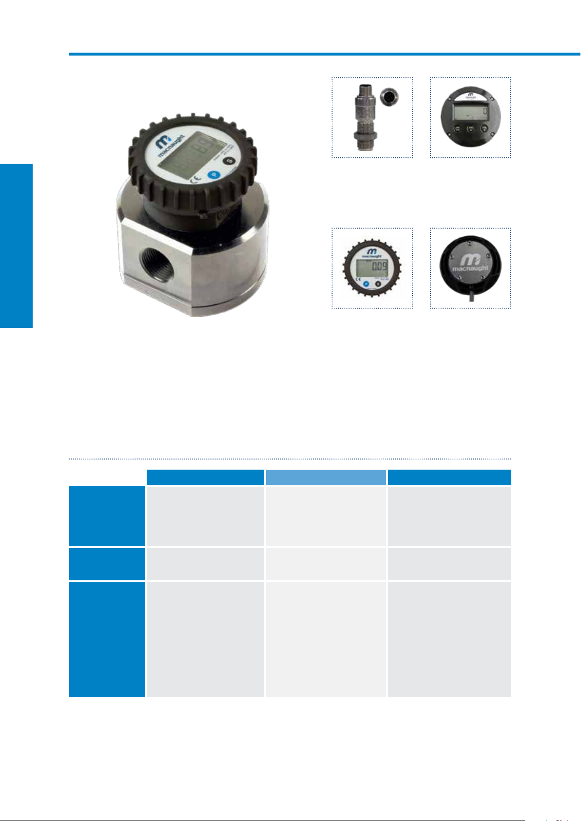
MX100 4” DIGITAL FLOW METERS
SUITABLE FOR FLOW RANGE 1201200L/MIN
MX-SERIES FLOW METERS
MX100F-1SE
Aluminium steel body with LCD register
Output variations:
B - Ex approved (Ex ia)
Intrinsically Safe - NPN
N - Ex approved (Ex ia)
Intrinsically Safe - NAMUR
T - High Temp. Pulse
Max temp- 150ºC
D - PR
LCD Display (12mm)
E - PRA
LCD Display (12mm)
with outputs
F - ER
LCD Display (17mm)
G- ERA
LCD Display (17mm)
H- ERB
LCD Display (17mm)
Batch controller
A - Standard Pulse
Reel/Hall Effect
I - Standard Pulse
Reel/Reed Effect
J - Standard Pulse
Hall/Hall Effect
K - High Resolution
Hall NPN
The MX100 4” Digital Flow Meter are suitable for flows between 120-1200L/min. The 4” Digital Flow Meters
have an accuracy of +/- 0.5% and provides exceptional levels of reliability and durability.
SPECIFICATIONS
MX100F MX100S
Materials of
Construction
Meter Body
Design Specifications
Process Connections
Technical
Specifications
Flow rate
Operating Temperature
Max. Operating
Pressure**
Accuracy
Repeatability
Nominal K-Factor
*Temperature based on standard pulse output - subject to change dependant on rotor and output type, contact Macnaught technical support for further investigations
** Pressure rating subject to change as per flange rating
Rotor
Seals
Range*
Cast Aluminium (6061)
Aluminium (6061)
Fluorocarbon (FKM)
Threaded
3” G
3” NPT
<5cP
220-1000L/min
60-250USG/min
-40 - 120ºC
-40 - 248ºF
175 psi
12 bar
+/- 0.5%
+/- 0.03%
2.3 Pulses/L
Flange
ANSI CLASS 150
DIN PN16
JIS 10k
>5cP
120-1200L/min
31.7-317USG/min
Cast Aluminium (6061)
Aluminium (6061)
PTFE encapsulated (FEP)
Threaded
3” G
3” NPT
<5cP
220-1000L/min
60-250USG/min
-40 - 120ºC
-40 - 248ºF
175 psi
12 bar
+/- 0.5%
+/- 0.03%
2.3 Pulses/L
Flange
ANSI CLASS 150
DIN PN16
JIS 10k
>5cP
120-1200L/min
31.7-317USG/min
28 Macnaught | Positive Displacement Flow Meters
Page 31

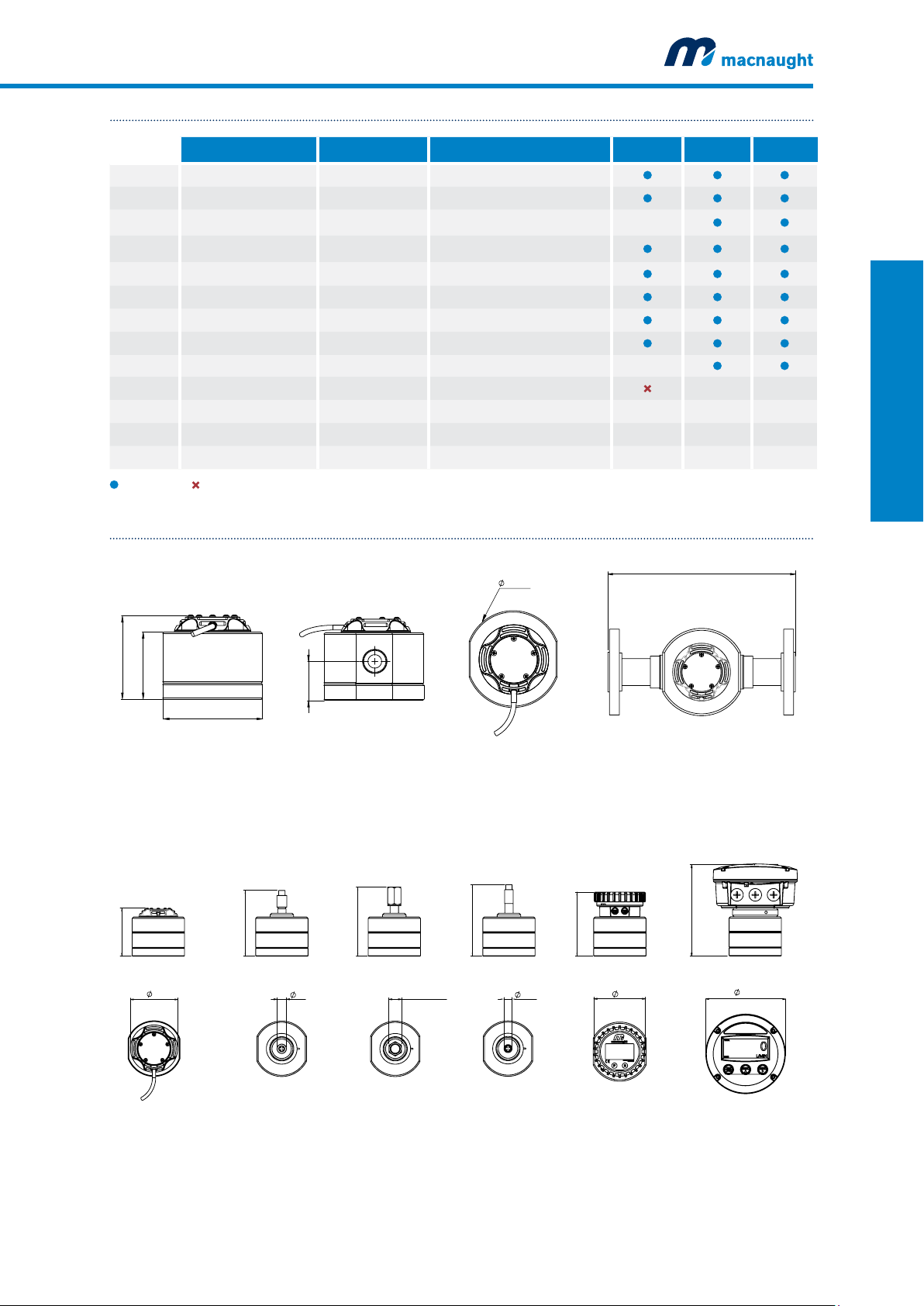
OUTPUTS TYPS
DESCRIPTION SWITCH TYPE OUTPUT TYPE MX100F MX100S
X No Output - No Output
A Standard Pulse Reed /Hall (NPN) Pulse (1m flying lead)
B Ex approved (Ex ia) Hall (NPN) Pulse (2m DIN cable) —
D PR (LCD 12mm display) - Display 12mm
E PRA (LCD 12mm display) - Display 12mm, 4-20mA output, Pulse
F ER (LCD 17mm display) - Display 17mm
G ERA (LCD 17mm display) - Display 17mm, 4-20mA output, Pulse
H ERB (LCD 17mm display) - Display 17mm + Batch Control
N Ex Approved (Ex ia NAMUR) NAMUR Pulse (2m DIN cable) —
T High Temp. Pulseerature Hall (NPN) Pulse
I Reed/Reed Reed/Reed Pulse (1m flying lead) — —
J Hall/Hall Hall/Hall Pulse (1m flying lead) — —
K High Resolution (omnipolar) Hall (NPN) Pulse (1m flying lead) — —
MX-SERIES FLOW METERS
Available Not Available
DIMENSIONS
OUTPUT A
PULSER - Standard
A
179mm
OUTPUT B
PULSER - Exia
S
Only with stainless steel rotors
254mm
141mm
PULSER AND DISPLAY HEIGHT - A
OUTPUT
N
PULSER - Exia
—
Consult Macnaught Technical regarding availability
436mm*
OUTPUT
T
PULSER - High Temp.
OUTPUT D,E
DISPLAY - LCD 12mm
OUTPUT
F,G,H
DISPLAY - LCD 17mm
242mm
74mm
276mm
19mm
283mm
287mm
25.4mm (1") A/F
*Length subject to change refer to appendix B (pg. 88) for full dimension variations
16mm
273mm
99mm
326mm
161mm
macnaught.com.au 29
Page 32

Page 33

M-SERIES
FLOW METERS
Page 34

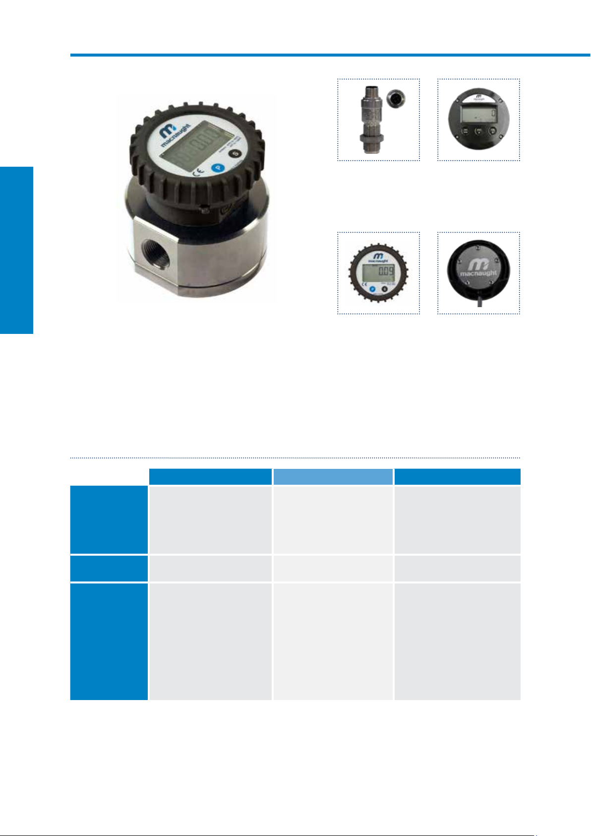
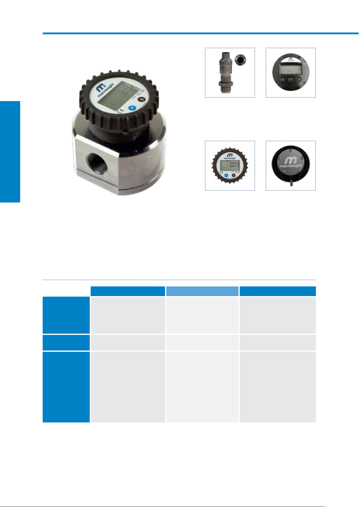
MSERIES FLOW METERS
MECHANICAL FLOW METE RS
The Mechanical Flow Meters range is the original meter range from Macnaught. They are available with
reliable mechanical displays offer a measurement option for unpowered or remote sites. All Macnaught Flow
Meters are supplied with an individual Test Report.
EXPLODED DIAGRAM
Output
Choose between standard
mechanical or heavy duty
mechanical register
Materials of
construction
Choose material
based on pressure
and fluid type
M-SERIES FLOW METERS
Rotor type
Select rotor type based
on the viscosity of the
fluid and fluid type
Port size
Choose meter port
size based on flow
rate desired
Port connection
Based on desired pipe
connection
32 Macnaught | Positive Displacement Flow Meters
Page 35

PRODUCT IDENTIFICATION SYSTEM
F012-1S3
CATEGORY METER/ROTOR/SEAL MODELS
F
F
M SS/PPS/FEP M012 - 050
S
012 1/2”
025 1”
012
040 1½”
050 2”
075 3”
100 4”
MATERIALS OF CONSTRUCTION
AL/PPS/FKM F012 - 050
AL/AL/FKM F075 -100
AL/SS/FEP S025
AL/AL/FEP S040 - 100
PORT SIZE
M-SERIES FLOW METERS
1
S
3
PORT CONNECTION MODELS
1 G (Litres Display)
2 NPT (US Gallons Display)
3 NPT (Litres Display)
4 BSP Rc (Litres Display)
ROTOR MODELS
S Standard Rotors Category F and M
T* High Temperature Category M and S025
V High Viscosity
*T type rotors are offered in Aluminium for category S040 to S100
OUTPUT MODELS
3 Standard Mechanical 012-050
4 Heavy Duty Mechanical All Models
AL material for F075-F100, S040-S100
All Models
PPS material for F012-F050
SS material for M025-M050
macnaught.com.au 33
Page 36

MSERIES FLOW METERS
PULSE FLOW METE RS STANDARD
The Macnaught Pulse Flow Meter range are the original meter range from Macnaught. They offer a compact
and robust metal body, manufactured from high quality grades of cast aluminium and stainless steel. For
highly corrosive chemical applications, BR42B grade PPS material is used to deliver superior stability*.
EXPLODED DIAGRAM
Output
Choose between Hall
Effect or Reed Switch
M-SERIES FLOW METERS
Rotor type
Select rotor type based
on the viscosity of the
fluid and fluid type
Port size
Choose meter port
size based on flow
rate desired
Materials of
construction
Choose material
based on pressure
and fluid type
Port connection
Based on desired pipe
connection
34 Macnaught | Positive Displacement Flow Meters
Page 37

PRODUCT IDENTIFICATION SYSTEM
F006-1SA
CATEGORY BODY/ROTOR/SEAL MODELS
F AL/SS/FKM All Models
F
M SS/SS/FFKM M006/M009
S AL/SS/FFKM S006/S009
CR
MATERIALS OF CONSTRUCTION
PPS/PPS/FFKM CR006 and CR009
PPS/PPS/FEP CR025
006
1
S
A
PORT SIZE MODELS
006 1/4” All models
009 1/4” All models
025 1” Category CR only
PORT CONNECTION MODELS
1 G Category F, M and S only
2 NPT All models
4 Rc All models
ROTOR TYPE MODELS
S Standard F and CR category only
T High Temp. Pulse M and S category only
V High Viscosity 009 only; Not available for CR
OUTPUT TYPE MODELS
1 Reed/Hall
2 Reed/Reed 006/009 Single reed ONLY
A Reed/Hall DIN connection
B
Reed/Reed DIN
connection
Flying lead for 006/009
User connection for CR025
Not Available for CR025
M-SERIES FLOW METERS
macnaught.com.au 35
Page 38

MSERIES FLOW METERS
PULSE FLOW METERS HIGH PRESSURE
Macnaught High Pressure Flow Meters are manufactured from robust stainless steel body utilizing high quality
billet suitable for use in the harshest environments. Designed to withstand pressures from 3000psi to 8000psi,
the Macnaught High Pressure Flow Meters fit virtually any high pressure liquid measurement requirements. All
Macnaught Flow Meters are supplied with an individual Test Report.
EXPLODED DIAGRAM
Output
Choose between Hall
Effect or Reed Switch
M-SERIES FLOW METERS
Rotor type
Select rotor type based
on the viscosity of the
fluid and fluid type
Port size
Choose meter port
size based on flow
rate desired
Port connection
Based on desired pipe
connection
Materials of
construction
Choose material
based on pressure
and fluid type
36 Macnaught | Positive Displacement Flow Meters
Page 39

PRODUCT IDENTIFICATION SYSTEM
MH009-1T1
CATEGORY METER/ROTOR/SEAL MODELS
MH
MH
MATERIALS OF CONSTRUCTION
SS/SS/FFKM MH006-009
SS/SS/FEP
SS/PPS/FEP
M H 012
009
1
T
1
PORT SIZE MODELS
006 1/4”
009 1/4”
012 1/2”
PORT CONNECTION MODELS
1 G
2 NPT
ROTOR TYPE MODELS
T High Temp. Pulseerature All Models
V High Viscosity MH009 and MH012
OUTPUT SWITCH TYPE
1 Pulse Output Single Hall for MH006/009. Reed/Hall for MH012
2 Pulse Output Single Reed for MH006/009. Dual Reed for MH012
All Models
All Models
M-SERIES FLOW METERS
macnaught.com.au 37
Page 40

MSERIES FLOW METERS
PULSE FLOW METERS CUSTODY TRANSFER
The Macnaught Custody Transfer meter range are the original meter range from Macnaught. They offer a
compact and robust body manufactured from high quality grades of cast Aluminium and Stainless steel.
Macnaught Custody Transfer meters are certified and approved by the National Measurement Institute (NMI)
and supplied with an individual Test Report.
EXPLODED DIAGRAM
Output
Choose between
Dual Sensor options
M-SERIES FLOW METERS
Rotor type
Select rotor type based
on the viscosity of the
fluid and fluid type
Port size
Choose meter port
size based on flow
rate desired
Port connection
Based on desired pipe
connection
Materials of
construction
Choose material
based on pressure
and fluid type
38 Macnaught | Positive Displacement Flow Meters
Page 41

PRODUCT IDENTIFICATION SYSTEM
WM10SSP-1S9
WM10
SS
7 10 40 50 80 100
1” 1” 1½” 2” 3” 4”
RR PPS/PPS/FKM WM7
AR AL/PPS/FKM WM10-WM50
AA AL/AL/FKM WM80-WM100
SS SS/SS/FEP WM10-WM50
WM PORT SIZE
MATERIALS OF CONSTRUCTION
CATEGORY BODY/ROTOR/SEAL MODELS
M-SERIES FLOW METERS
P
1
C9
OUTPUT* MODELS
P Dual Reed All models
FB Encoder WM50-WM100
PORT CONNECTION MODELS
1 Rp *Rc for WM7
2 NPT WM10-100
3 ANSI WM10-80
14 3” ANSI WM100 only
OPTIONAL CONFIGURATION MODELS
C Foot mount WM50-100
C9 Foot mount, Air eliminator and strainer WM50-WM100
*Additional output options also available as accessories. Contact Macnaught Technical Support Team for more information
macnaught.com.au 39
Page 42

M1 ¼” PULSE FLOW METERS
SUITABLE FOR FLOW RANGE 0.5100L/HR
F006-1S1
Aluminium body with flying lead
CR006-1SA
PPS body with DIN variation
Macnaught ¼” Pulse Flow Meters are a small capacity meter in the M-SERIES range. Differentiated by its
flow rate capabilities. Suitable for flows between 0.5-100L/hr. The ¼” Pulse Flow Meters have an accuracy
of +/- 0.5% and provides exceptional levels of reliability and durability.
SPECIFICATIONS
F006 S006 M006 CR006
Materials of
Construction
Meter Body
M-SERIES FLOW METERS
Design
Specifications
Process Connections
Technical
Specifications
Flow rate
Non-lubricating fluids
Operating Temperature
Max. Operating
Pressure
Accuracy
Repeatability
Nominal K-Factor
Rotor
Seals
Range*
Aluminium
Stainless Steel
Fluorocarbon (FKM)
¼” G
¼” NPT
<5cP
2-100L/hr
0.5-26USG/hr
-40 - 80ºC
-40 - 176ºF
800 psi
55 bar
+/- 0.5%
+/- 0.03%
1000 Pulses/L
>5cP
0.5-100L/hr
0.13-26USG/hr
6-100L/hr
1.58-26USG/hr
Aluminium
Stainless Steel
Perfluoroelastomer (FFKM)
¼” G
¼” NPT
<5cP
2-100L/hr
0.5-26USG/hr
-40 - 120ºC
-40 - 248ºF
800 psi
55 bar
+/- 0.5%
+/- 0.03%
1000 Pulses/L
>5cP
0.5-100L/hr
0.13-26USG/hr
6-100L/hr
1.58-26USG/hr
Stainless Steel
Stainless Steel
Perfluoroelastomer (FFKM)
¼” G
¼” NPT
<5cP
2-100L/hr
0.5-26USG/hr
-40 - 120ºC
-40 - 248ºF
800 psi
55 bar
+/- 0.5%
+/- 0.03%
1000 Pulses/L
>5cP
0.5-100L/hr
0.13-26USG/hr
6-100L/hr
1.58-26USG/hr
PPS
PPS
Perfluoroelastomer (FFKM)
¼” BSP (Rc)
¼” NPT
<5cP
2-100L/hr
0.5-26USG/hr
-40 - 80ºC
-40 - 176ºF
75 psi
5 bar
+/- 0.5%
+/- 0.03%
1000 Pulses/L
>5cP
0.5-100L/hr
0.13-26USG/hr
6-100L/hr
1.58-26USG/hr
*Temperature based on standard pulse output - subject to change dependant on rotor and output type, contact Macnaught technical support for further investigations
40 Macnaught | Positive Displacement Flow Meters
Page 43

OUTPUTS
17mm
PREFIX OUTPUT SWITCH TYPE F006 S006 M006 CR006
1
2
A
B
Available Not Available
Pulse output Reed/Hall Flying Lead
Pulse output Reed Flying Lead
Pulse output Reed/Hall DIN Connection
Pulse output Reed/Reed DIN Connection
DIMENSIONS
M006/F006/S006
DIN variation
M006/F006/S006
Flying Lead
CR006
DIN variation
50mm
50mm
64mm
51mm
51mm
51mm
13mm
13mm
1m
59mm
59mm
59mm
42mm
17mm
M-SERIES FLOW METERS
45mm
17mm
42mm
17mm
CR006
Flying Lead
64mm
51mm
1m
59mm
45mm
macnaught.com.au 41
Page 44

M1 ¼” HIGH PRESSURE FLOW METERS
SUITABLE FOR FLOW RANGE 0.5100L/HR
MH006-1T1
Stainless steel body with pulser cap
Also available as optional accessories:
DR
LCD Display (12mm)
DRA
LCD Display (12mm) with
outputs
Macnaught ¼” High Pressure Flow Meters are a small capacity meter in the M-SERIES range. Suitable for
flows between 0.5-100L/hr. The ¼” High Pressure Flow Meters are manufactured from high quality billet
for enhanced material reliability with pressure ratings of up to 8000psi and have an accuracy of +/- 0.5% to
provide exceptional levels of reliability and durability.
SPECIFICATIONS
MH006
Materials of
Construction
M-SERIES FLOW METERS
Design Specifications
Operating Temperature
Pulse Output Options
Local Display Options
*Temperature based on standard pulse output - subject to change dependant on rotor and output type, contact Macnaught technical support for further investigations
Meter Body
Process Connections ¼” G
Technical
Specifications
Flow rate
Non-lubricating fluids
Pressure
Accuracy
Repeatability
Nominal K-Factor
Type DR
Type DRA
Stainless Steel
Rotor
Stainless Steel
Seals
Perfluoroelastomer (FFKM)
¼” NPT
<5cP
2-100L/hr
0.5-26USG/hr
6-100L/hr
1.58-26USG/hr
-40 - 120ºC
Range*
-40 - 248ºF
8000 psi
557 bar
+/- 0.5%
+/- 0.03%
1000 Pulses/L
Pulser
Single Hall Effect
Pulser
Single Reed Switch
LCD display (12mm)
LCD display (12mm)
>5cP
0.5-100L/hr
0.13-26USG/hr
No Outputs
Outputs: Scaled Pulse,
4-20mA and Hi/Lo Flow Alarm
42 Macnaught | Positive Displacement Flow Meters
Page 45

DIMENSIONS
100
69 79
23
ISOMETRIC VIEW
MH006
86
ISOMETRIC VIEW
MH006 with DR
Display
69 39
83
100
89
23
ISOMETRIC VIEW
M-SERIES FLOW METERS
69 79
23
macnaught.com.au 43
Page 46

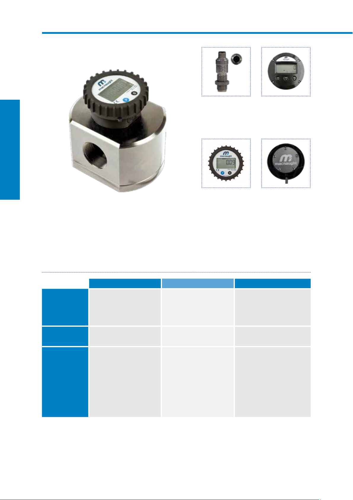
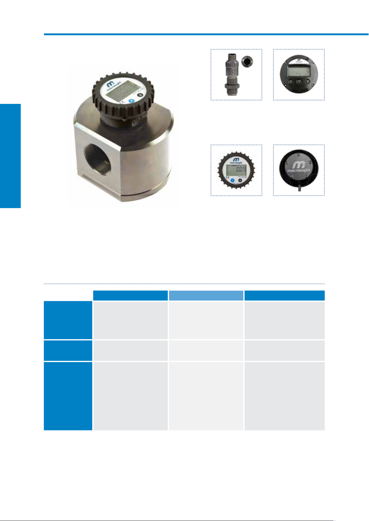
M2 ¼” PULSE FLOW METERS
SUITABLE FOR FLOW RANGE 15500L/HR
F009-1S1
Aluminium body with flying lead
CR009-1SA
PPS body with DIN variation
Macnaught ¼” Pulse Flow Meters are a small capacity meter in the M-SERIES range. Differentiated by its
flow rate capabilities. Suitable for flows between 15-500L/hr. The ¼” Pulse Flow Meters have an accuracy of
+/- 0.5% and provides exceptional levels of reliability and durability.
SPECIFICATIONS
F009 S009 M009 CR009
Materials of
Construction
Meter Body
M-SERIES FLOW METERS
Design Specifications
Process Connections ¼” G
Technical
Specifications
Flow rate
Operating Temperature
Max. Operating
Pressure
Accuracy
Repeatability
Nominal K-Factor
*Temperature based on standard pulse output - subject to change dependant on rotor and output type, contact Macnaught technical support for further investigations
Rotor
Seals
Range*
Aluminium
Stainless Steel
Fluorocarbon (FKM)
¼” NPT
<5cP
25-500L/hr
6.6-132USG/hr
-40 - 80ºC
-40 - 176ºF
800 psi
55 bar
+/- 0.5%
+/- 0.03%
400 Pulses/L
>5cP
15-500L/hr
4-132USG/hr
Aluminium
Stainless Steel
Perfluoroelastomer (FFKM)
¼” G
¼” NPT
<5cP
25-500L/hr
6.6-132USG/hr
-40 - 120ºC
-40 - 248ºF
800 psi
55 bar
+/- 0.5%
+/- 0.03%
400 Pulses/L
>5cP
15-500L/hr
4-132USG/hr
Stainless Steel
Stainless Steel
Perfluoroelastomer (FFKM)
¼” G
¼” NPT
<5cP
25-500L/hr
6.6-132USG/hr
-40 - 120ºC
-40 - 248ºF
800 psi
55 bar
+/- 0.5%
+/- 0.03%
400 Pulses/L
>5cP
15-500L/hr
4-132USG/hr
PPS
PPS
Perfluoroelastomer (FFKM)
¼” BSP (Rc)
¼” NPT
<5cP
25-500L/hr
6.6-132USG/hr
-40 - 80ºC
-40 - 176ºF
75 psi
5 bar
+/- 1.0%
+/- 0.03%
400 Pulses/L
>5cP
15-500L/hr
4-132USG/hr
44 Macnaught | Positive Displacement Flow Meters
Page 47

OUTPUTS
17mm
PREFIX OUTPUT SWITCH TYPE F009 S009 M009 CR009
1
2
A
B
Available Not Available
Pulse output Reed/Hall Flying Lead
Pulse output Reed Flying Lead
Pulse output Reed/Hall DIN Connection
Pulse output Reed/Reed DIN Connection
DIMENSIONS
M009/F009/S009
DIN variation
M009/F009/S009
Flying Lead
CR009
DIN variation
50mm
50mm
64mm
51mm
51mm
51mm
13mm
13mm
1m
59mm
59mm
59mm
42mm
17mm
M-SERIES FLOW METERS
45mm
17mm
42mm
17mm
CR009
Flying Lead
64mm
51mm
1m
59mm
45mm
macnaught.com.au 45
Page 48

M2 ¼” HIGH PRESSURE FLOW METERS
SUITABLE FOR FLOW RANGE 15500L/HR
MH009-1T1
Stainless steel body with pulser cap
Also available as optional accessories:
DR
LCD Display (12mm)
DRA
LCD Display (12mm) with
outputs
Macnaught ¼” High Pressure Flow Meters are a small capacity meter in the M-SERIES range. Suitable for
flows between 25-500L/hr. The ¼” High Pressure Flow Meters are manufactured from high quality billet for
enhanced material reliability with pressure ratings of up to 8000psi and have an accuracy of +/- 0.5% to
provide exceptional levels of reliability and durability.
SPECIFICATIONS
MH009
Materials of
Construction
M-SERIES FLOW METERS
Design Specifications
Operating Temperature
Pulse Output Options
Local Display Options
*Temperature based on standard pulse output - subject to change dependant on rotor and output type, contact Macnaught technical support for further investigations
Meter Body
Process Connections
Technical
Specifications
Flow rate
Max. Operating
Pressure
Accuracy
Repeatability
Nominal K-Factor
Type DR
Type DRA
Stainless Steel
Rotor
Stainless Steel
Seals
Perfluoroelastomer (FFKM)
Threaded
¼” G
¼” NPT
<5cP
25-500L/hr
6.6-132USG/hr
-40 - 120ºC
Range*
-40 - 248ºF
8000 psi
557 bar
+/- 0.5%
+/- 0.03%
400 Pulses/L
Pulser
Single Hall Effect
Pulser
Single Reed Switch
LCD display (12mm)
LCD display (12mm)
>5cP
15-500L/hr
4-132USG/hr
No Outputs
Outputs: Scaled Pulse,
4-20mA and Hi/Lo Flow Alarm
46 Macnaught | Positive Displacement Flow Meters
Page 49

DIMENSIONS
100
69 79
23
ISOMETRIC VIEW
MH009
86
ISOMETRIC VIEW
MH009 with DR
Display
69 39
83
100
89
23
ISOMETRIC VIEW
M-SERIES FLOW METERS
69 79
23
macnaught.com.au 47
Page 50

M4 ½” HIGH PRESSURE FLOW METERS
SUITABLE FOR FLOW RANGE 230L/MIN
MH012-1T1
Stainless steel body with pulser cap
Also available as optional accessories:
DR
LCD Display (12mm)
DRA
LCD Display (12mm) with
outputs
Macnaught ½” High Pressure Flow Meters are suitable for low to medium flow range of 2-30L/min. The ½” High
Pressure Flow Meters are manufactured from high quality billet for enhanced material reliability with pressure
ratings of up to 3000psi and have an accuracy of +/- 0.5% to provide exceptional levels of reliability and durability.
SPECIFICATIONS
MH012
Materials of
Construction
Meter Body
M-SERIES FLOW METERS
Design Specifications
Process Connections
Technical
Specifications
Flow rate
Operating Temperature
Pressure
Accuracy
Repeatability
Nominal K-Factor
Pulse Output Options
Local Display Options
*Temperature based on standard pulse output - subject to change dependant on rotor and output type, contact Macnaught technical support for further investigations
Type DR
Type DRA
Stainless Steel
Rotor
Stainless Steel
PPS option
Seals
PTFE encapsulated (FEP)
Threaded
½” G
½” NPT
<5cP
3-25L/min
0.6-6.6USG/min
-40 - 120ºC
Range*
-40 - 248ºF
3000psi
207 Bar
+/- 1.0%
+/- 0.03
112 Pulses/L
Pulser
Dual Reed/Hall
Pulser
Dual Reed Switch
LCD display (12mm)
LCD display (12mm)
>5cP
2-30L/min
0.5-8USG/min
No Outputs
Outputs: Scaled Pulse,
4-20mA and Hi/Lo Flow Alarm
48 Macnaught | Positive Displacement Flow Meters
Page 51
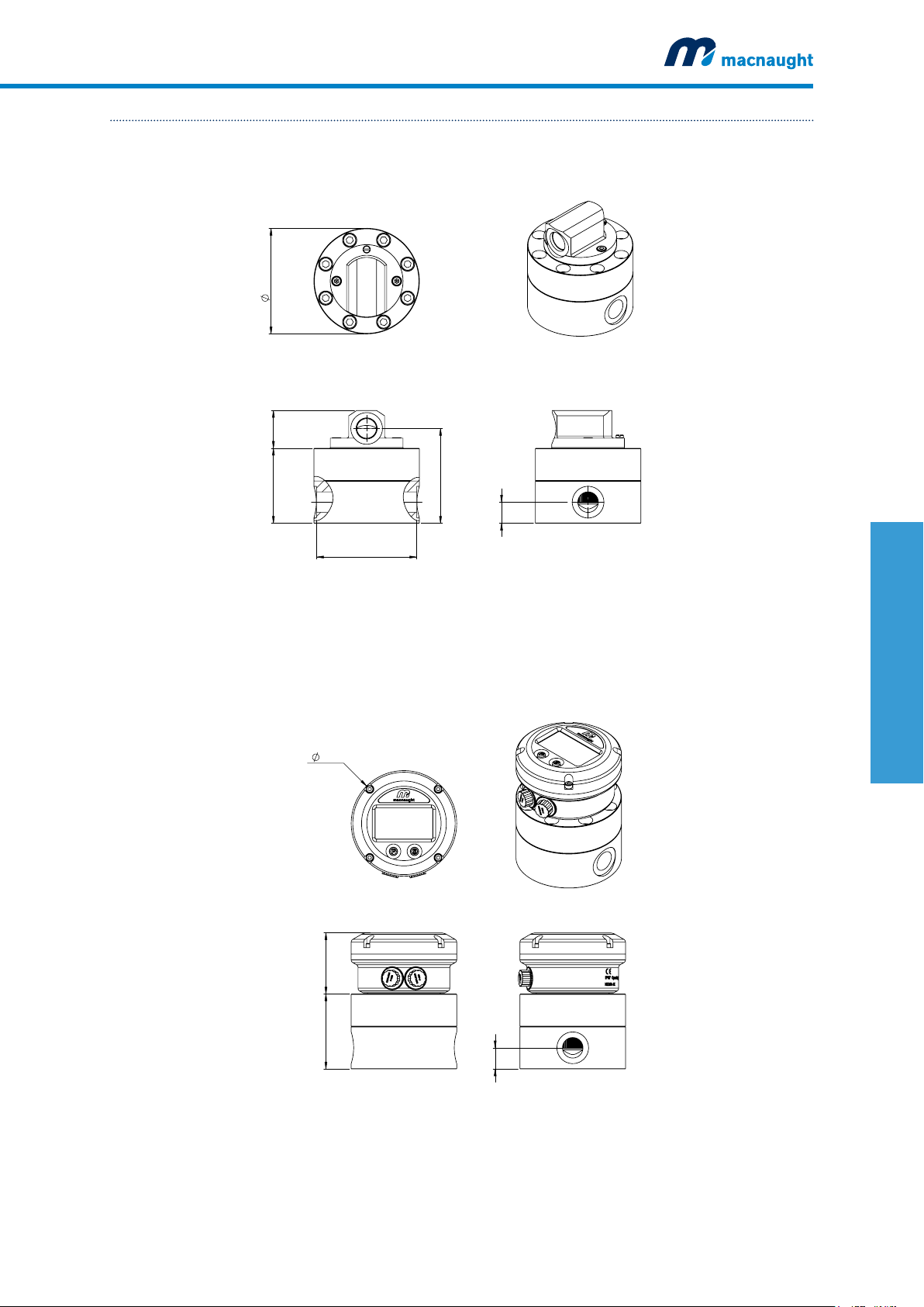
DIMENSIONS
71
58
20
100
ISOMETRIC VIEW
MH012-1T1
MH012
100
ISOMETRIC VIEW
MH012 with DR
Display
71 36
100
95
90
20
M-SERIES FLOW METERS
ISOMETRIC VIEW
58
71
20
macnaught.com.au 49
Page 52

M4 ½” MECHANICAL METERS
SUITABLE FOR FLOW RANGE 230L/MIN
F012-1S3
Aluminium body with standard mechanical display
Output variations:
Type 3
Standard Mechanical Display
Type 4
Heavy Duty Mechanical Display
Designed and built to suit a broad range of industrial applications, the Macnaught ½” Mechanical Meters
are suitable for flows between 2-30L/min. The ½” Mechanical Meters have an accuracy of +/- 1.0% and
provides exceptional levels of reliability and durability. These meters are an ideal solution for remote sites or
where ease of installation, accuracy and reliability are the priority.
SPECIFICATIONS
F012 M012
Materials of
Construction
M-SERIES FLOW METERS
Design Specifications
*Temperature based on standard pulse output - subject to change dependant on rotor and output type, contact Macnaught technical support for further investigations
Meter Body
Process Connections
Technical
Specifications
Flow rate
Max. Operating
Temperature*
Max. Operating
Pressure
Accuracy
Repeatability
Mechanical Display
Type 3 - Standard
Type 4 - Heavy Duty
Cast Aluminium
Rotor
PPS
Seals
Fluorocarbon (FKM)
Threaded
½” G
½” NPT
<5cP
3-25L/min
0.6-6.6USG/min
-40 - 80ºC
-40 - 176ºF
500 psi
35 bar
+/- 1.0%
+/- 0.03%
Polypropylene (IP56)
Aluminium (IP67)
>5cP
2-30L/min
0.5-8USG/min
Cast Stainless Steel
PPS
Stainless Steel
PTFE encapsulated (FEP)
Threaded
½” G
½” NPT
<5cP
3-25L/min
0.6-6.6USG/min
-40 - 80ºC
-40 - 176ºF
500psi
35 bar
+/- 1.0%
+/-0.03%
Polypropylene (IP56)
Aluminium (IP67)
>5cP
2-30L/min
0.5-8USG/min
50 Macnaught | Positive Displacement Flow Meters
Page 53

DIMENSIONS
154mm
F012
M012
A
64mm
100mm
TYPE 3
MECHANICAL REGISTER - STANDARD
122mm
115mm
DISPLAY HEIG HT - A
MECHANICAL REGISTER - HEAVY DUTY
148mm
106mm 48mm
TYPE 4
173mm
TYPE 4
24mm
M-SERIES FLOW METERS
macnaught.com.au 51
Page 54

M7 1” PULSE FLOW METERS
SUITABLE FOR FLOW RANGE 380L/MIN
Also available as optional accessories:
DR
LCD Display (12mm)
DRA
LCD Display (12mm) with
outputs
CR025-2S1
PPS body with pulser cap
ER
LCD Display (17mm)
ERA
LCD Display (17mm) with
outputs
ERB
LCD Display (17mm) with
batch control output
The Macnaught 1” Pulse Flow Meters are specialised meters suitable for aggressive chemicals and water
based products. Suitable for flows between 3-80L/min. The 1” Pulse Flow Meters have an accuracy of +/-
0.5% and provides exceptional levels of reliability and durability.
SPECIFICATIONS
CR025
Materials of
Construction
M-SERIES FLOW METERS
Design Specifications
Operating Temperature
Pulse Output Options
Local Display Options
*Temperature based on standard pulse output - subject to change dependant on rotor and output type, contact Macnaught technical support for further investigations
Meter Body
Process Connections
Technical
Specifications
Flow rate
Max. Operating
Pressure
Accuracy
Repeatability
Nominal K-Factor
Type DR
Type DRA
PPS
Rotor
PPS
Seals
PTFE encapsulated (FEP)
Threaded
1” BSP (Rc)
1” NPT
<5cP
8-70L/min
2-18.5 USG/min
-40 - 80ºC
Range*
-40-176ºF
150 psi
10 Bar
+/- 0.5%
+/- 0.03%
52 Pulses/L
Pulser
Reed/Hall Effect
Pulser
Reed/Reed Switch
Dual Hall
LCD display (12mm)
LCD display (12mm)
>5cP
3-80L/min
0.8-21 USG/min
No Outputs
Outputs: Scaled Pulse,
4-20mA and Hi/Lo Flow Alarm
52 Macnaught | Positive Displacement Flow Meters
Page 55

DIMENSIONS
CR025
CR025 with ER
Display
100mm
35mm
82mm
161mm
ISOMETRIC VIEW
100mm
27mm
109mm
M-SERIES FLOW METERS
ISOMETRIC VIEW
CR025 with DR
Display
85mm
82mm
102mm
109mm
109mm
27mm
82mm 80mm
macnaught.com.au 53
Page 56

M7 1” CUSTODY TRANSFER METERS
SUITABLE FOR FLOW RANGE 1470L/MIN
WM7RRP-1
PPS body with pulser cap
The Macnaught 1” Custody Transfer meters are specialised meters suitable for aggressive chemicals and
water based products. Suitable for flows between 14-70L/min. The 1” Pulse Flow Meters are NMI approved
and have an accuracy of +/- 0.5% and provides exceptional levels of reliability and durability.
SPECIFICATIONS
WM7
Materials of
Construction
Meter Body
M-SERIES FLOW METERS
Design Specifications
Process Connections
Technical
Specifications
Flow rate 14-70L/min
Operating Temperature
Max. Operating
Pressure
Accuracy
Repeatability
Nominal K-Factor
Pulse Output Options
*Temperature based on standard pulse output - subject to change dependant on rotor and output type, contact Macnaught technical support for further investigations
Rotor
Seals
Range*
Pulser
Pulser
Pulser
PPS
PPS
Fluorocarbon (FKM)
Threaded
1” BSP Rc
1” NPT
3.6-19.8USG/min
-40 - 80ºC
-40 - 176ºF
150psi
10 Bar
+/- 0.5%
+/- 0.03%
52 Pulses/L
Dual Hall Effect
Dual Reed
Reed/Hall Effect
54 Macnaught | Positive Displacement Flow Meters
Page 57
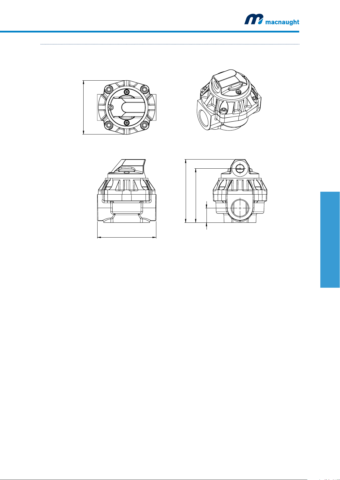
DIMENSIONS
WM7
100mm
117mm
100mm
ISOMETRIC VIEW
M-SERIES FLOW METERS
109mm
27mm
macnaught.com.au 55
Page 58

M10 1” MECHANICAL METERS
SUITABLE FOR FLOW RANGE 6120L/MIN
F025-1S3
Aluminium body with standard mechanical display
Output variations:
Type 3
Standard Mechanical Display
Type 4
Heavy Duty Mechanical Display
Designed and built to suit a broad range of industrial applications, the Macnaught 1” Mechanical Meters
are suitable for flows between 6-120L/min. The 1” mechanical meters have an accuracy of +/- 1.0% and
provides exceptional levels of reliability and durability. These meters are an ideal solution for remote sites or
where ease of installation, accuracy and reliability are the priority.
SPECIFICATIONS
F025 M025 S025
Materials of
Construction
M-SERIES FLOW METERS
Design Specifications
Operating Temperature
*Temperature based on standard pulse output - subject to change dependant on rotor and output type, contact Macnaught technical support for further investigations
**Pressure subject to change as per flange rating
Meter Body
Process Connections
Technical
Specifications
Flow rate
Max. Operating
Pressure**
Accuracy
Repeatability
Mechanical Display
Type 3 - Standard
Type 4 - Heavy Duty
Rotor
Seals
Range*
Cast Aluminium
PPS
Fluorocarbon (FKM)
Threaded
1” G
1” NPT
<5cP
10-100L/min
2.6-26USG/min
-40 - 80ºC
-40 - 176ºF
500 psi
35 Bar
+/- 1.0%
+/- 0.03%
Polypropylene (IP56)
Aluminium (IP67)
Flange
ANSI CLASS 150
DIN PN16
JIS 10k
>5cP
6-120L/min
1.6-32USG/min
Cast Stainless Steel
PPS
Stainless Steel
PTFE encapsulated (FEP)
Threaded
1” G
1” NPT
<5cP
10-100L/min
2.6-26USG/min
-40 - 80ºC
-40 - 176ºF
500 psi
35 Bar
+/- 1.0%
+/- 0.03%
Polypropylene (IP56)
Aluminium (IP67)
Flange
ANSI CLASS 150
DIN PN16
JIS 10k
>5cP
6-120L/min
1.6-32USG/min
Cast Aluminium
Stainless Steel
PTFE encapsulated (FEP)
Threaded
1” G
1” NPT
<5cP
10-100L/min
2.6-26USG/min
-40 - 120ºC
-40 - 248ºF
500 psi
35 Bar
+/- 1.0%
+/- 0.03%
Polypropylene (IP56)
Aluminium (IP67)
Flange
ANSI CLASS 150
DIN PN16
JIS 10k
>5cP
6-120L/min
1.6-32USG/min
56 Macnaught | Positive Displacement Flow Meters
Page 59

DIMENSIONS
28mm
100
133
28
F025
S025
A
100mm
133mm
28mm
56mm 106mm
284mm
ANSI
M025
294mm
A
100mm
M-SERIES FLOW METERS
143mm
TYPE 3
MECHANICAL REGISTER - STANDARD
158mm
DISPLAY HEIGHT - A
TYPE 4
MECHANICAL REGISTER - HEAVY DUTY
184mm
ANSI
115mm
162mm
173mm
macnaught.com.au 57
Page 60

M10 1” CUSTODY TRANSFER METERS
SUITABLE FOR FLOW RANGE 24120L/MIN
WM10SSP-1
Stainless steel body with pulser cap
The 1” Custody Transfer Meters are the medium capacity meter in the M-SERIES range. Suitable for flows
between 24-120L/min. The 1” Custody Transfer Meters are NMI approved and have an accuracy of
+/- 0.5% and provides exceptional levels of reliability and durability. It has ability to handle a wide range of
fluid viscosities with exceptional levels of repeatability and durability.
SPECIFICATIONS
WM10AR WM10SS
Materials of
Construction
Meter Body
M-SERIES FLOW METERS
Design Specifications
Process Connections
Technical Specifications
Operating Temperature
Pulse Output Options*
*Temperature based on standard pulse output - subject to change dependant on rotor and output type, contact Macnaught technical support for further investigations
**Pressure subject to change as per flange rating
Flow rate 24-120L/min
Max. Operating
Pressure**
Accuracy
Repeatability
Nominal K-Factor
Cast Aluminium
Rotor
PPS
Seals
Fluorocarbon (FKM)
Threaded
1” G
1” NPT
6.3-31.7USG/min
-40 - 80ºC
Range*
-40 - 176ºF
1000 psi
69 Bar
+/- 0.5%
+/- 0.03%
36 Pulses/L
Pulser Dual Reed switch
Dual Hall switch
Flange
ANSI CLASS 150
Cast Stainless Steel
Stainless Steel
PTFE encapsulated (FEP)
Threaded
1” G
1” NPT
24-120L/min
6.3-31.7USG/min
-40 - 120ºC
-40 - 248ºF
1200 psi
83 Bar
+/- 0.5%
+/- 0.03%
36 Pulses/L
Dual Reed switch
Dual Hall switch
Flange
ANSI CLASS 150
*Additional output options also available as accessories. Contact Macnaught Technical Support Team for more information
58 Macnaught | Positive Displacement Flow Meters
Page 61

DIMENSIONS
WM10AR
139mm
121mm
28mm
133mm
284mm
WM10SS
112mm
139mm
121mm
M-SERIES FLOW METERS
ANSI
28mm
143mm
294mm
112mm
ANSI
macnaught.com.au 59
Page 62

M40 1½” MECHANICAL METERS
SUITABLE FOR FLOW RANGE 10250L/MIN
F040-1S3
Aluminium body with standard mechanical display
Output variations:
Type 3
Standard Mechanical Display
Type 4
Heavy Duty Mechanical Display
Designed and built to suit a broad range of industrial applications, the Macnaught 1½” Mechanical Meters
are suitable for flows between 10-250L/min. The 1½” Mechanical Meters have an accuracy of +/- 1.0% and
provides exceptional levels of reliability and durability. These meters are an ideal solution for remote sites or
where ease of installation, accuracy and reliability are the priority.
SPECIFICATIONS
F040 M040 S040
Materials of
Construction
M-SERIES FLOW METERS
Design Specifications
Operating Temperature
*Temperature based on standard pulse output - subject to change dependant on rotor and output type, contact Macnaught technical support for further investigations
**Pressure subject to change as per flange rating
Meter Body
Process Connections
Technical
Specifications
Flow rate
Max. Operating
Pressure**
Accuracy
Repeatability
Mechanical Display
Type 3 - Standard
Type 4 - Heavy Duty
Rotor
Seals
Range*
Cast Aluminium
PPS
Fluorocarbon (FKM)
Threaded
1½” G
1½” NPT
<5cP
15-235L/min
4-62USG/min
-40 - 80ºC
-40 - 176ºF
500 psi
35 Bar
+/- 1.0%
+/- 0.03%
Polypropylene (IP56)
Aluminium (IP67)
Flange
ANSI CLASS 150
DIN PN16
JIS 10k
>5cP
10-250L/min
2.6-66 USG/min
Cast Stainless Steel
PPS
Stainless Steel
PTFE encapsulated (FEP)
Threaded
1½” G
1½” NPT
<5cP
15-235L/min
4-62USG/min
-40 - 80ºC
-40 - 176ºF
500 psi
35 Bar
+/- 1.0%
+/- 0.03%
Polypropylene (IP56)
Aluminium (IP67)
Flange
ANSI CLASS 150
DIN PN16
JIS 10k
>5cP
10-250L/min
2.6-66 USG/min
Cast Aluminium
Aluminium
Stainless Steel
PTFE encapsulated (FEP)
Threaded
1½” G
1½” NPT
<5cP
15-235L/min
4-62USG/min
-40 - 120ºC
-40 - 248ºF
500 psi
35 Bar
+/- 1.0%
+/- 0.03%
Polypropylene (IP56)
Aluminium (IP67)
Flange
ANSI CLASS 150
DIN PN16
JIS 10k
>5cP
10-250L/min
2.6-66 USG/min
60 Macnaught | Positive Displacement Flow Meters
Page 63

DIMENSIONS
124
44
132
F040
M040
S040
A
132mm
44mm
124mm
270mm*
ANSI
DISPLAY HEIGHT - A
TYPE 3
MECHANICAL REGISTER - STANDARD
190mm
144mm
TYPE 4
MECHANICAL REGISTER - HEAVY DUTY
216mm
173mm
178mm
M-SERIES FLOW METERS
*Length subject to change refer to appendix B (pg. 89) for full dimension variations
macnaught.com.au 61
Page 64

M40 1½” CUSTODY TRANSFER METERS
SUITABLE FOR FLOW RANGE 50250L/MIN
WM40AR
Aluminium body with pulser cap
WM40SS
Stainless steel body with pulser cap
The 1½” Custody Transfer Meters are the medium to large capacity meter in the M-SERIES range. Suitable
for flows between 50-250L/min. The 1½” Custody Transfer Meters are NMI approved and have an accuracy
of +/- 0.5% and provides exceptional levels of reliability and durability. It has ability to handle a wide range of
fluid viscosities with exceptional levels of repeatability and durability.
SPECIFICATIONS
WM40AR WM40SS
Materials of
Construction
M-SERIES FLOW METERS
Design Specifications
Operating Temperature
Pulse Output Options
*Temperature based on standard pulse output - subject to change dependant on rotor and output type, contact Macnaught technical support for further investigations
**Pressure subject to change as per flange rating
Meter Body
Process Connections
Technical
Specifications
Flow rate 50-250L/min
Max. Operating
Pressure**
Accuracy
Repeatability
Nominal K-Factor
Rotor
Seals
Range*
Pulser
Pulser
Cast Aluminium
PPS
Fluorocarbon (FKM)
Threaded
1½” G
1½” NPT
13-66USG/min
-40 - 80ºC
-40 - 176ºF
800 psi
55 Bar
+/- 0.5%
+/- 0.03%
14.5 Pulses/L
Dual Reed switch
Dual Hall Switch
Flange
ANSI CLASS 150
Cast Stainless Steel
Stainless Steel
PTFE encapsulated (FEP)
Threaded
1½” G
1½” NPT
50-250L/min
13-66USG/min
-40 - 120ºC
-40 - 248ºF
1000 psi
69 Bar
+/- 0.5%
+/- 0.03%
14.5 Pulses/L
Dual Reed switch
Dual Hall Switch
Flange
ANSI CLASS 150
*Additional output options also available as accessories. Contact Macnaught Technical Support Team for more information
62 Macnaught | Positive Displacement Flow Meters
Page 65

DIMENSIONS
WM40AR
WM40SS
153mm
171mm
44mm
124mm
144mm
M-SERIES FLOW METERS
270mm*
ANSI
*Length subject to change refer to appendix B (pg. 89) for full dimension variations
Refer to appendix B (pg. 92) for dimensions of air eliminators
macnaught.com.au 63
Page 66

M50 2” MECHANICAL METERS
SUITABLE FOR FLOW RANGE 15500L/MIN
F050-1S3
Aluminium body with standard mechanical display and BSP thread adaptors
Output variations:
Type 3
Standard Mechanical Display
Type 4
Heavy Duty Mechanical Display
Designed and built to suit a broad range of industrial applications, the Macnaught 2” Mechanical Meters
are suitable for flows between 15-500L/min. The 2” Mechanical Meters have an accuracy of +/- 1.0% and
provides exceptional levels of reliability and durability. These meters are an ideal solution for remote sites or
where ease of installation, accuracy and reliability are the priority.
SPECIFICATIONS
F050 M050 S050
Materials of
Construction
M-SERIES FLOW METERS
Design Specifications
Operating Temperature
Mechanical Display
*Temperature based on standard pulse output - subject to change dependant on rotor and output type, contact Macnaught technical support for further investigations
**Pressure subject to change as per flange rating
Meter Body
Process Connections
Technical
Specifications
Flow rate
Max. Operating
Pressure**
Accuracy
Repeatability
Type 3 - Standard
Type 4 - Heavy Duty
Rotor
Seals
Range*
Cast Aluminium
PPS
Fluorocarbon (FKM)
Threaded
2” G
2 “ NPT
<5cP
15-500L/min
4-130USG/min
-40 - 80ºC
-40 - 176ºF
500psi
35 Bar
+/- 1.0%
+/- 0.03%
Polypropylene (IP56)
Aluminium (IP67)
Flange
ANSI CLASS 150
DIN PN16
JIS 10k
>5cP
15-500L/min
4-130USG/min
Cast Stainless Steel
PPS
Stainless Steel
PTFE encapsulated (FEP)
Threaded
2” G
2 “ NPT
<5cP
15-500L/min
4-130USG/min
-40 - 80ºC
-40 - 176ºF
500psi
35 Bar
+/- 1.0%
+/- 0.03%
Polypropylene (IP56)
Aluminium (IP67)
Flange
ANSI CLASS 150
DIN PN16
JIS 10k
>5cP
15-500L/min
4-130USG/min
Cast Aluminium
Stainless Steel
Aluminium
PTFE encapsulated (FEP)
Threaded
2” G
2 “ NPT
<5cP
15-500L/min
4-130USG/min
-40 - 120ºC
-40 - 248ºF
500psi
35 Bar
+/- 1.0%
+/- 0.03%
Polypropylene (IP56)
Aluminium (IP67)
Flange
ANSI CLASS 150
DIN PN16
JIS 10k
>5cP
15-500L/min
4-130USG/min
64 Macnaught | Positive Displacement Flow Meters
Page 67

DIMENSIONS
F050
M050
S050
A
157mm
60mm
120mm
89mm
106mm
264mm
ANSI/DIN/JIS
TYPE 3
MECHANICAL REGISTER - STANDARD
215mm
210mm
M-SERIES FLOW METERS
G/NPT
DISPLAY HEIG HT - A
TYPE 4
MECHANICAL REGISTER - HEAVY DUTY
241mm
178mm
195mm
186mm
macnaught.com.au 65
Page 68
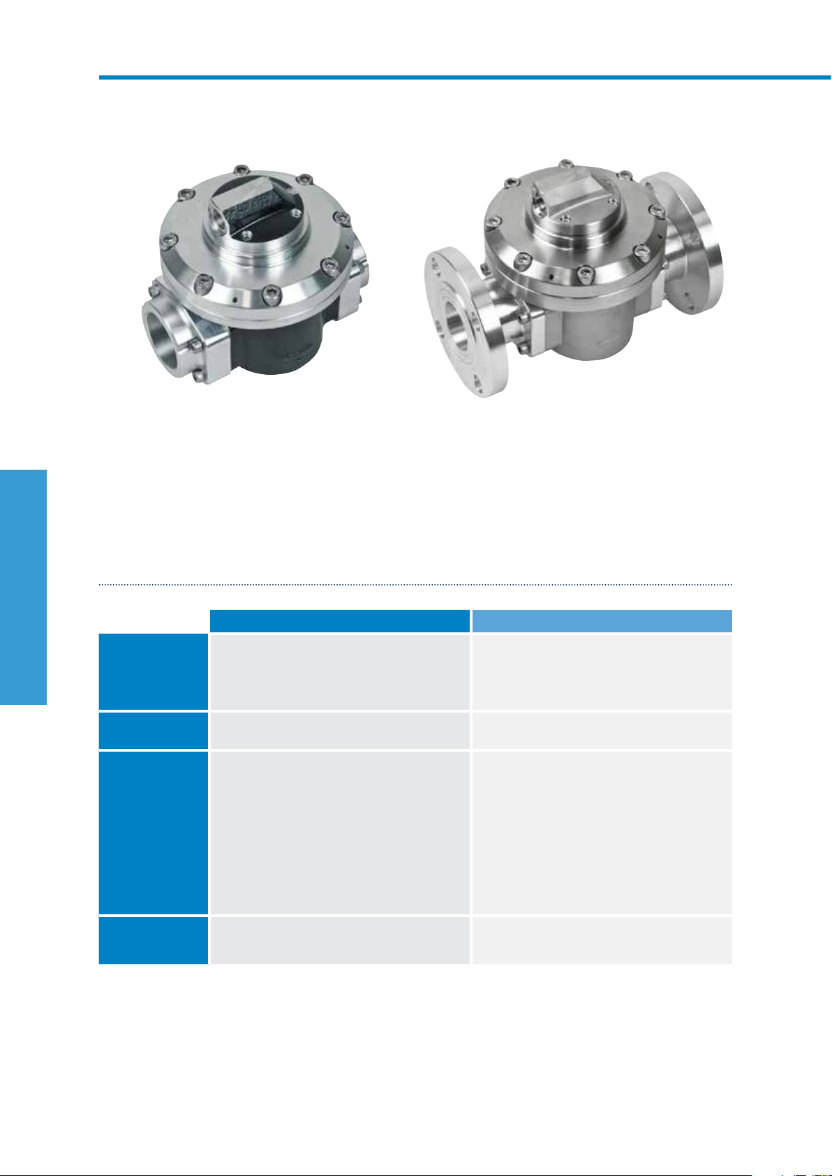
M50 2” CUSTODY TRANSFER METERS
SUITABLE FOR FLOW RANGE 70350L/MIN
WM50AR
Aluminium body with pulser cap and BSP thread adaptors
WM50SS
Stainless steel body with pulser cap and ANSI flanges
The 2” Custody Transfer Meters are the large capacity meter in the M-SERIES range. Suitable for flows
between 70-350L/min. The 2” Custody Transfer Meters are NMI approved and have an accuracy of +/-
0.5% and provides exceptional levels of reliability and durability. It has ability to handle a wide range of fluid
viscosities with exceptional levels of repeatability and durability.
SPECIFICATIONS
WM50AR WM50SS
Materials of
Construction
M-SERIES FLOW METERS
Design Specifications
Operating Temperature
Pulse Output Options*
*Temperature based on standard pulse output - subject to change dependant on rotor and output type, contact Macnaught technical support for further investigations
**Pressure subject to change as per flange rating
Meter Body
Process Connections
Technical
Specifications
Flow rate 70-350L/min
Max. Operating
Pressure**
Accuracy
Repeatability
Nominal K-Factor
Rotor
Seals
Range*
Pulser
Pulsar
Pulser
Cast Aluminium
PPS
Fluorocarbon (FKM)
Threaded
2” G
2” NPT
18-92.4USG/min
-40 - 80ºC
-40 - 176ºF
800 psi
55 Bar
+/- 0.5%
+/- 0.03%
6.68 Pulses/L
Dual Reed Switch
Dual Hall Switch
Encoder
Flange
ANSI CLASS 150
Cast Stainless Steel
Stainless Steel
PTFE encapsulated (FEP)
Threaded
2” G
2” NPT
70-350L/min
18-92.4USG/min
-40 - 120ºC
-40 - 248ºF
800 psi
55 Bar
+/- 0.5%
+/- 0.03%
6.68 Pulses/L
Dual Reed Switch
Dual Hall Switch
Encoder
Flange
ANSI CLASS 150
*Additional output options also available as accessories. Contact Macnaught Technical Support Team for more information
66 Macnaught | Positive Displacement Flow Meters
Page 69

DIMENSIONS
WM50ARP
Foot Mount Option
WM50ARP
WM50SSP
203mm
144mm
178mm
144mm
60mm
137mm
226mm
197mm
179mm
197mm
179mm
186mm
120
M-SERIES FLOW METERS
Flange
Connections
264mm
ANSI/DIN/JIS
56mm
120mm
210mm
G/NPT
Refer to appendix B (pg. 90) for dimensions of air eliminators
macnaught.com.au 67
Page 70

M80 3” MECHANICAL METERS
SUITABLE FOR FLOW RANGE 20733L/MIN
F075-1S4
Aluminium body with heavy duty mechanical display and ANSI flanges
Output variations:
Type 4
Heavy Duty Mechanical Display
Designed and built to suit a broad range of industrial applications, the Macnaught 3” Mechanical Meters
are suitable for flows between 20-733L/min. The 3” Mechanical Meters have an accuracy of +/- 1.0% and
provides exceptional levels of reliability and durability. These meters are an ideal solution for remote sites or
where ease of installation, accuracy and reliability are the priority.
SPECIFICATIONS
F075 S075
Materials of
Construction
M-SERIES FLOW METERS
Design Specifications
Operating Temperature
Pulse Output Options
*Temperature based on standard pulse output - subject to change dependant on rotor and output type, contact Macnaught technical support for further investigations
**Pressure subject to change as per flange rating
Meter Body
Process Connections
Technical
Specifications
Flow rate
Max. Operating
Pressure**
Accuracy
Repeatability
Type 4 - Heavy Duty Aluminium (IP67) Aluminium (IP67)
Rotor
Seals
Range*
Cast Aluminium
Aluminium
Fluorocarbon (FKM)
Threaded
3” G
3” NPT
<5cP
60-600L/min
17-170USG/min
-40 - 120ºC
-40 - 248ºF
175 psi
12 Bar
+/- 1.0%
+/- 0.03%
Flange
ANSI CLASS 150
DIN PN16
JIS 10k
>5cP
20-733L/min
5-194USG/min
Cast Aluminium
Aluminium
PTFE encapsulated (FEP)
Threaded
3” G
3” NPT
<5cP
60-600L/min
17-170USG/min
-40 - 120ºC
-40 - 248ºF
175 psi
12 Bar
+/- 1.0%
+/- 0.03%
Flange
ANSI CLASS 150
DIN PN16
JIS 10k
>5cP
20-733L/min
5-194USG/min
68 Macnaught | Positive Displacement Flow Meters
Page 71

DIMENSIONS
F075
S075
254mm
212mm
226mm
436mm
ANSI/DIN/JIS
141mm
78mm
200mm 85mm
302mm
M-SERIES FLOW METERS
G/NPT
macnaught.com.au 69
Page 72

M80 3” CUSTODY TRANSFER METERS
SUITABLE FOR FLOW RANGE 140700L/MIN
WM80AAP-3
Aluminium body with pulser cap and ANSI flanges
The 3” Custody Transfer Meters are the large capacity meter in the M-SERIES range. Suitable for flows
between 140-700L/min. The 3” Custody Transfer Meters are NMI approved and have an accuracy of +/-
0.5% and provides exceptional levels of reliability and durability. It has ability to handle a wide range of fluid
viscosities with exceptional levels of repeatability and durability.
SPECIFICATIONS
WM80AA
Materials of
Construction
M-SERIES FLOW METERS
Design Specifications
Operating Temperature
Pulse Output Options*
*Temperature based on standard pulse output - subject to change dependant on rotor and output type, contact Macnaught technical support for further investigations
**Pressure subject to change as per flange rating
Meter Body
Process Connections
Technical
Specifications
Flow rate 140-700L/min
Max. Operating
Pressure**
Accuracy
Repeatability
Nominal K-Factor
Rotor
Seals
Range*
Pulser
Pulser
Pulsar
Cast Aluminium
Aluminium
Fluorocarbon (FKM)
Threaded
3” G
3” NPT
36.9-184.9USG/min
-40 - 120ºC
-40 - 248ºF
175psi
12 Bar
+/- 0.5%
+/- 0.03%
2.58 Pulses/L
Dual Reed switch
Dual Hall switch
Encoder
Flange
ANSI CLASS 150
*Additional output options also available as accessories. Contact Macnaught Technical Support Team for more information
70 Macnaught | Positive Displacement Flow Meters
Page 73

DIMENSIONS
WM80AAP-3
254mm
226mm
436mm
ANSI
212mm
239mm
141mm
78mm
302mm
G/NPT
M-SERIES FLOW METERS
Refer to appendix B (pg. 90) for dimensions of air eliminators
macnaught.com.au 71
Page 74

M100 4” MECHANICAL METERS
SUITABLE FOR FLOW RANGE 1201200L/MIN
F100-1S4
Aluminium body with heavy duty mechanical display with ANSI flanges
Output variations:
Type 4
Heavy Duty Mechanical Display
Designed and built to suit a broad range of industrial applications, the Macnaught 4” Mechanical Meters are
suitable for flows between 120-1200L/min. Suitable for fuels, lubricants and non-corrosive fluids of up to a
viscosity of 1000cP. The 4” Mechanical Meters have an accuracy of +/- 1.0% and provides exceptional levels
of reliability and durability. These meters are an ideal solution for remote sites or where ease of installation,
accuracy and reliability are the priority.
SPECIFICATIONS
F100 S100
Materials of
M-SERIES FLOW METERS
*Temperature based on standard pulse output - subject to change dependant on rotor and output type, contact Macnaught technical support for further investigations
**Pressure subject to change as per flange rating
Construction
Meter Body
Design Specifications
Process Connections
Technical
Specifications
Flow rate
Operating Temperature
Max. Operating
Pressure***
Accuracy
Repeatability
Pulse Output Options
Type 4 - Heavy Duty Aluminium (IP67) Aluminium (IP67)
Rotor
Seals
Range*
Cast Aluminium
Aluminium
Fluorocarbon (FKM)
Threaded
3” G
3” NPT
<5cP
220-1000L/min
60-250USG/min
-40 - 120ºC
-40 - 248ºF
175 psi
12 Bar
+/- 1.0%
+/- 0.03%
Flange
4” ANSI CLASS 150
4” DIN PN16
4’ JIS 10k
>5cP
120-1200L/min
31.7-317USG/min
Cast Aluminium
Aluminium
PTFE encapsulated (FEP)
Threaded
3” G
3” NPT
<5cP
220-1000L/min
60-250USG/min
-40 - 120ºC
-40 - 248ºF
175 psi
12 Bar
+/- 1.0%
+/- 0.03%
Flange
4” ANSI CLASS 150
4” DIN PN16
4’ JIS 10k
>5cP
120-1200L/min
31.7-317USG/min
72 Macnaught | Positive Displacement Flow Meters
Page 75

DIMENSIONS
F100-1S4
S100-1S4
339mm
212mm
220mm
583mm*
85mm
191mm
108mm
246mm
302mm*
M-SERIES FLOW METERS
ANSI/DIN/JIS
G/NPT
*Length subject to change refer to appendix B (pg. 89) for full dimension variations
Refer to appendix B (pg. 90) for dimensions of air eliminators
macnaught.com.au 73
Page 76

M100 4” CUSTODY TRANSFER METERS
SUITABLE FOR FLOW RANGE 2401200L/MIN
WM100AAP-3
Aluminium Body with Pulser Cap with Flanges
The 4” Custody Transfer Meters are the large capacity meter in the M-SERIES range. Suitable for flows
between 240-1200L/min. Suitable for fuels, lubricants and corrosive fluids (stainless steel only) of up to a
viscosity of 1000cP. The 4” Custody Transfer Meters are NMI approved and have an accuracy of +/- 0.5%
and provides exceptional levels of reliability and durability.
SPECIFICATIONS
WM100AA
Materials of
Construction
M-SERIES FLOW METERS
Design Specifications
Operating Temperature
Pulse Output Options
*Temperature based on standard pulse output - subject to change dependant on rotor and output type, contact Macnaught technical support for further investigations
**Pressure subject to change as per flange rating
Meter Body
Process Connections
Technical
Specifications
Flow rate 240-1200L/min
Max. Operating
Pressure**
Accuracy
Repeatability
Nominal K-Factor
Rotor
Seals
Range*
Pulser
Pulser
Pulsar
Cast Aluminium
Aluminium
Fluorocarbon (FKM)
Threaded
3” G
3” NPT
63.4-317USG/min
-40 - 120ºC
-40-248ºF
175 psi
12 Bar
+/- 0.5%
+/- 0.03%
2.3 Pulses/L
Dual Reed switch
Dual Hall switch
Encoder
Flange
4” ANSI CLASS 150
*Additional output options also available as accessories. Contact Macnaught Technical Support Team for more information
74 Macnaught | Positive Displacement Flow Meters
Page 77

DIMENSIONS
WM100AAP-3
339mm
212mm
220mm
583mm*
108mm
191mm
302mm*
285mm
M-SERIES FLOW METERS
ANSI/DIN/JIS
G/NPT
*Length subject to change refer to appendix B (pg. 89) for full dimension variations
Refer to appendix B (pg. 90) for dimensions of air eliminators
macnaught.com.au 75
Page 78

Page 79

ACCESSORIES
Page 80

ACCESSORIES
PULSER MODULES
The Pulser Output Options are designed to complement the MX Blind meters series. These options provide
the flexibility to apply a style of housing that best satisfies the application requirements.
TYPE T
HIGH TEMP.
PULSEERATURE
STANDARD PULSE*
Switch Type Reed/Hall Effect NPN open collector NAMUR NPN open collector
Construction PP (polypropylene) Stainless Steel Cuzn, Chrome plated Stainless Steel
IP rating IP67 IP67 IP67 IP67
Max temp 120°C (248°F) 85°C (185°F) 85°C (185°F) 150°C (302°F)
Intrinsically safe
Approvals
*Options of lengths: 1m, 5m and 10m
TYPE A
TYPE B
INTRINSICALLY SAFE
CHECK✓ CHECK✓
ATEX, CSA, FM
II I G Ex ia IIC T6
TYPE N
INTRINSICALLY SAFE
ATEX, IECEx
II G Ex ia IIC T4..T6 Ga
II 1 D Ex ia IIIC T115OC Da
PULSER MODULE OPTIONS
Macnaught offer a range of Pulser modules to suit a wide variety of industrial flow metering needs.
Incorporating Reed and NPN Open Collector switching technology and locking mechanism to facilitate
simple integration into any logging and control system.
ACCESSORIES
DIN COMPACT INDUSTRIAL PULSER CAP
Output Pulser Pulser
Cable connection (M12) DIN socket M20 or ½” NPT
Switch Type
Construction PP (polypropylene) Aluminium or Stainless Steel
IP rating I P67 IP67
Max temp 120ºC (248ºF) 120ºC (248ºF)
Part number
Hall/Hall Switch
MXD-HH
Reed/Hall Effect
Dual Reed Switch
Dual Hall Effect
Reed/Reed Switch
MXD-RR
Reed/Hall
Switch
MXD-RH
Aluminium
MXD-ACM-1 (Reed/Hall)
MXD-ACM-2 (Reed/Reed)
MXD-ACN-1 (Reed/Hall)
MXD-ACN-2 (Reed/Reed)
Reed/Hall Effect
Dual Reed Switch
MXD-SCM-1 (Reed/Hall)
Stainless Steel
78 Macnaught | Positive Displacement Flow Meters
Page 81
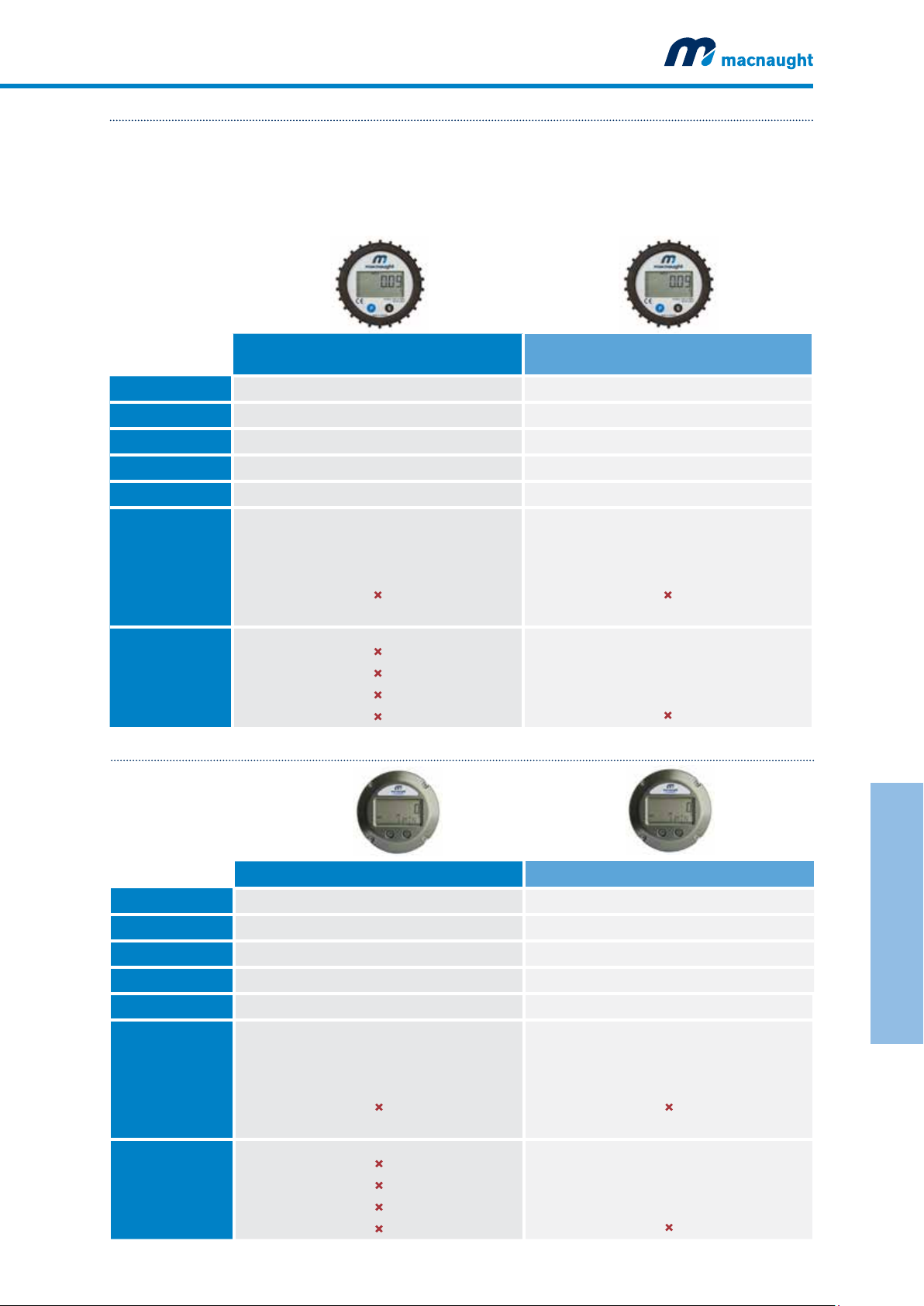
PR DIGITAL DISPLAY SERIES 12MM DIGIT
The PR Series is a fully programmable 12mm LCD Digital Register displaying Flow Rate, Accumulated (Nonresettable) and Batch (Resettable) Totals. The output options available include 4-20mA output, scaled pulse
output and a Hi/Lo Flow Alarm. Rated at IP67, the UV resistant glass reinforced polypropylene housing
makes the PR Series suitable for both indoor and outdoor use in light-medium duty industrial applications.
The PR display is also available in both Meter Mount and Remote Mount version
TYPE D
METER MOUNT
Description Liquid Crystal Display Liquid Crystal Display with outputs
Construction PP (polypropylene) PP (polypropylene)
Wall mount option PR-WM PRA-WM
IP rating IP67 IP67
Max temp 60ºC (140ºF) 60ºC (140ºF)
Digit size (upper/lower)
Pulse/Transistor Output
Batch Control output
Display
Accumulated total
Resettable total
Preset total
Flow rate
Outputs
4-20 mA (passive)
Flow Alarm
PR DISPLAY
12mm/8mm
CHECK✓
CHECK✓
CHECK
CHECK✓
CHECK
CHECK
CHECK
CHECK
PRA DISPLAY
DR DIGITAL DISPLAY SERIES 12MM DIGIT
TYPE E
12mm/8mm
CHECK✓
CHECK✓
CHECK
CHECK✓
CHECK✓
CHECK✓
CHECK✓
CHECK
METER MOUNT DR DRA
Description Reflective, UV resistant numeric and alphanumeric LCD Reflective, UV resistant numeric and alphanumeric LCD
Construction Aluminium exterior with polycarbonate windows Aluminium exterior with polycarbonate windows
Wall mount option DR-WM DRA-WM
IP rating IP67 IP67
Max temp 60ºC (140ºF) 60ºC (140ºF)
Digit size (upper/lower)
Pulse/Transistor Output
Batch Control output
Display
Accumulated total
Resettable total
Preset total
Flow rate
Outputs
4-20 mA (passive)
Flow Alarm
12mm/8mm
CHECK✓
CHECK✓
CHECK
CHECK✓
CHECK
CHECK
CHECK
CHECK
12mm/8mm
CHECK✓
CHECK✓
CHECK
CHECK✓
CHECK✓
CHECK✓
CHECK✓
CHECK
macnaught.com.au 79
ACCESSORIES
Page 82

ACCESSORIES
ER DIGITAL DISPLAY SERIES 17MM DIGIT
The ER Series is a fully programmable 17mm LCD Digital Register displaying Flow Rate, Accumulated
(Non-resettable) and Batch (Resettable) Totals. The output options available include 4-20mA and scaled
pulse output. Rated at IP67, the robust Aluminium housing makes the ER Series suitable for both indoor
and outdoor use in heavy duty industrial applications. The ER display is also available in both Meter Mount
(Aluminium) and Remote Mount (Aluminium or plastic) versions.
TYPE F
METER MOUNT
Description Liquid Crystal Display Liquid Crystal Display with outputs Single stage Batch Controller
Construction Aluminium Aluminium Aluminium
IP rating IP67 IP67 IP67
Max temp 120°C (248°F) 80°C (176°F) 80°C (176°F)
Digit size (upper/lower)
Pulse/Transistor Output
Batch Control output
Display
Accumulated total
Resettable total
Preset total
Flow rate
Outputs
4-20 mA (passive)
Flow Alarm
ER DISPLAY
17mm/8mm
CHECK✓
CHECK✓
CHECK
CHECK✓
CHECK
CHECK
CHECK
CHECK
TYPE G
ERA DISPLAY
17mm/8mm
CHECK✓
CHECK✓
CHECK
CHECK✓
CHECK✓
CHECK✓
CHECK
CHECK
ERB DISPLAY
TYPE H
17mm/8mm
CHECK✓
CHECK✓
CHECKCHECK✓
CHECK✓
CHECK
CHECK
CHECK
✓
ACCESSORIES
ERRMP
REMOTE MOUNT
Description Liquid Crystal Display Liquid Crystal Display with outputs Single stage Batch Controller
Construction Aluminium or GRP (plastic) Aluminium or GRP (plastic) Aluminium or GRP (plastic)
IP rating IP67 IP67 IP67
Mounting Wall mount Wall mount Wall mount
Digit size (upper/lower)
Pulse/Transistor Output
Mechanical relay output
Batch Control output
Ex approved part
80 Macnaught | Positive Displacement Flow Meters
Display
Accumulated total
Resettable total
Preset total
Flow rate
Outputs
4-20 mA (passive)
Flow Alarm
numbers
ERRMA
17mm/8mm
CHECK✓
CHECK✓
CHECK
CHECK✓
CHECK
CHECK
CHECK
CHECK
CHECK
ERX-RMA (Aluminium)
ERX-RMP (Plastic)
ERARMP
ERARMA
17mm/8mm
CHECK✓
CHECK✓
CHECK
CHECK✓
CHECK✓
CHECK✓
CHECK
CHECK
CHECK
ERAX-RMA (Aluminium)
ERAX-RMP (Plastic)
ERBRMP
ERBRMA
17mm/8mm
CHECK✓
CHECK✓
CHECKCHECK✓
CHECK✓
CHECK
CHECK
CHECK
CHECK
✓
ERBX-RMA (Aluminium)
ERBX-RMP (Plastic)
Page 83

ER DIGITAL DISPLAY SERIES 17MM DIGIT
REMOTE MOUNT
Description Two stage Batch Controller Differential Flow Computer
Construction Aluminium front panel Aluminium or GRP (plastic)
IP rating IP67 (NEMA 4X) IP67 (NEMA 4X)
Mounting DIN panel mount Wall mount
Digit size (upper/lower)
Pulse/Transistor Output
Mechanical relay output
Batch Control output
Display
Accumulated total
Resettable total
Preset total
Flow rate
Outputs
4-20 mA (passive)
Flow Alarm
ERBPM
17mm/8mm
CHECK✓
CHECK✓
CHECK✓
CHECK✓
CHECK
✓
✓
✓
✓
ERSRMP
ERSRMA
17mm/8mm
CHECK✓
CHECK✓
CHECK
CHECK✓
CHECK✓
CHECK✓
CHECK
CHECK
CHECK
macnaught.com.au 81
ACCESSORIES
Page 84

ACCESSORIES
AIR ELIMINATOR & STRAINER
Y TYPE STRAINER
DESCRIPTION
• Aluminium body
• SS 316 basket
®
Seals
• Viton
• Mesh size: 100 Mesh (150µ)
• Air eliminators are available in 3 sizes:
- 50mm: Part Number BSA050
- 75mm: Part Number BSA075
- 100mm: Part Number BSA100
DESCRIPTION
• Body: CF8M
• Screen: SS316
• Working press: 800 psi/PN40
• Y-type strainers are available in 4 sizes:
» ¼” 200 mesh (74µ):
Part Number YS800-01 (BSP) YS800-02 (NPT)
» ½” 60 mesh (250µ):
Part Number YS012-01 (BSP)YS012-02 (NPT)
» 1” 60 mesh (250µ):
Part Number YS025-01 (BSP)YS025-02 (NPT)
» 1½” 60 mesh (250µ):
Part Number YS040-01 (BSP)YS040-01 (NPT)
ACCESSORIES
WALL MOUNT BRACKET
DESCRIPTION
• Aluminium wall mount bracket to suit models MX06-25
» Suitable for MX06: Part Number MXA-06-WM
» Suitable for MX09: Part Number MXA-09-WM
» Suitable for MX12: Part Number MXA-12-WM
» Suitable for MX19-25: Part Number MXA-25-WM
82 Macnaught | Positive Displacement Flow Meters
Page 85
SIGNAL CABLE
FIELD ATTACHABLE CONNECTOR
DESCRIPTION
• The Sensor Cable is a M12 5 position female connector
cable, to supplement the DIN Pulser Module
• Manufactured form polyurethane, the sensor cable is
highly resistant to acids, alkaline solutions, solvents and
salt water
• The Sensor cable is available in 4 options:
» 1.5 meters (right angle): Part Number MXD-C1.5
» 5 meters (right angle): Part Number MXD-C5
» 10 meters (right angle): Part Number MXD-C10
» 1.5 meters (straight): Part Number MXD-C1-5S
Please note: The Sensor cable should be ordered
separate to the DIN Pulser Module.
DESCRIPTION
• The Field Attachable Connector is a M12, right angled
female connector, to complement the DIN Pulser Module.
• The connector offers flexible on-site assembly via its 5
position, screw connection facility
• Part Number MXD-CF
macnaught.com.au 83
ACCESSORIES
Page 86

ACCESSORIES
DIGITAL FLOW METER EXTENSION ADAPTORS
Macnaught Digital Flow Meter Extensions Adaptors are manufactured from Stainless Steel 316 are suitable
for upgrading M-SERIES Flow Meters* (early models) to MX SERIES Flow Meters. Since end-to-end length
of MX Series flow meters are smaller than M-Series flow meters, these extension adaptors allow for users to
compensate the extra length and will adjust perfectly in existing pipework.
Macnaught offers these extension adaptors free of charge on request with every purchase of a MX meter.
ACCESSORIES
SPECIFICATIONS
Part Number
Telfon Seals
Viton Seals
MX12A-TE
MX12A-V
Size ½” ¾” 1” 1½” 2”
Suits models M X12 MX 19 MX25 MX40 MX50
DIMENSIONS
MX06F (AL)
MX06S (AL)
MX06P (SS)
MX09F (AL)
MX09S (AL)
MX09P (SS)
F006 (AL)
F009 (AL)
S006 (AL)
S009 (AL)
M1 (AL)
M2 (AL)
M006 (SS)
M009 (SS)
M1 (SS)
M2 (SS)
50mm
60mm
71mm
MX12P (SS)
MX12F (AL)
MX12S (AL)
F012 (AL)
S012 (AL)
M4 (AL)
M012 (SS)
M4 (SS)
P/N: MX12A-V suitable for MX12F
MX12A-TE suitable for MX12P or S
MX12 MX19 MX25 MX40 MX50
100mm
102mm
MX19A-TE
MX19A-V
MX19P (SS)
MX19F (AL)
MX19S (AL)
F019 (AL)
S019 (AL)
M6 (AL)
P/N: MX19A-V suitable for MX19F
MX19A-TE suitable for MX19P or S
MX25AA-TE
MX25AS-TE
MX25AA-V
133mm
MX40A-TE
MX40A-V
MX25P (SS)
M025 (SS)
M10 (SS)
MX25F (AL)
MX25S (AL)
F025 (AL)
S025 (AL)
M10 (AL)
MX50A-TE
MX50A-V
P/N: MX25A-V suitable for MX25F
MX25A-TE suitable for MX25P or S
P/N: MX25A-V suitable for MX25F
MX25A-TE suitable for MX25P or S
*
Applicable only for flow meters from 1/2” to 2” with BSP threaded connections.
84 Macnaught | Positive Displacement Flow Meters
133mm
143mm
Page 87

DIMENSIONS
MX40A-TE suitable for MX40P or S
MX50A-TE suitable for MX50P or S
MX40P (SS)
MX40F (AL)
MX40S (AL)
M40 (SS)
M40 (AL)
M040 (SS)
M040 (AL)
MX50P (SS)
MX50F (AL)
MX50S (AL)
M050 (SS)
M050 (AL)
124mm
150mm
P/N: MX40A-V suitable for MX40F
210mm
P/N: MX50A-V suitable for MX50F
ACCESSORIES
macnaught.com.au 85
Page 88

APPENDIX A
FLOW METER ACCURACY & PRESSURE LOSSES
Accuracy %
Accuracy %
+0.35
+0.15
–0.15
–0.35
+0.15
0
–0.15
M1-2
MX06/09
0
0 25
M50
MX50
Oil 20 mPa. s
Kerosene 1.2 mPa. s
Gasoline 0.4 mPa. s
50 75 100
Flow rate (%)
Fuel Oil 13 mPa. s
Kerosene 1.2 mPa. s
Water 1 mPa. s
Gasoline 0.4 mPa. s
60
50
40
30
20
10
30
20
10
Pressure loss (kPa)
Pressure loss (kPa)
M4-40
MX12-40
+0.15
0
–0.15
Accuracy %
Fuel Oil 13 mPa. s
Kerosene 1.2 mPa. s
Water 1 mPa. s
Gasoline 0.4 mPa. s
0 25 50 75 100
Flow rate (%)
M80
MX75
+0.15
0
–0.15
Accuracy %
Fuel Oil 13 mPa. s
Kerosene 1.2 mPa. s
Water 1 mPa. s
Gasoline 0.4 mPa. s
80
60
40
20
80
60
40
20
Pressure loss (kPa)
Pressure loss (kPa)
0 25 50 75 100
Flow rate (%)
M100
MX100
+0.15
0
–0.15
Accuracy %
Fuel Oil 13 mPa. s
Kerosene 1.2 mPa. s
Water 1 mPa. s
Gasoline 0.4 mPa. s
0 25 50 75 100
Flow rate (%)
80
60
40
20
0 25 50 75 100
Flow rate (%)
Pressure loss (kPa)
APPENDIXAPPENDICES
86 Macnaught | Positive Displacement Flow Meters
Page 89

FLOW METER ACCURACY & PRESSURE LOSSES
For Oil Service
Meter error (%) with kerosene (1.2mPa. s)
+0.5
0
Meter error %
–0.5
Pressure losses with heavy oil (19mPa. s)
0 25 50 75 100
M-SERIES
Flow rate (%)
Meter Sizes
M4
M10
M40
M50
M80
M100
MX SERIES
MX12
MX25
MX40
MX50
MX75
MX100
60
50
40
30
20
10
Meter error %
Pressure loss (kPa)
For Water Service
Meter Sizes
M-SERIES
Meter errors
+1.0
+0.5
0
–0.5
–1.0
Pressure losses
0 25 50 75 100
Flow rate (%)
M4
M7
M10
M40
MX-SERIES
MX12
MX19
MX25
MX40
15
10
5
Pressure loss (kPa)
macnaught.com.au 87
APPENDIXAPPENDICES
Page 90

APPENDIX B
436mm*
ACCESSORY DIMENSIONAL DATA
MX-Series Flange Dimension Data
A
A
METER SIZE PORT SIZE FLANGE TYPE LENGTH A
ANSI 436mm
DIN 436mm
MX75
ALUMINIUM
MX100
ALUMINIUM
3”
4”
3”
JIS 436mm
G 302mm
NPT 302mm
ANSI 574mm
DIN 574mm
JIS 574mm
G 302mm
NPT 302mm
APPENDICES
88 Macnaught | Positive Displacement Flow Meters
Page 91

ACCESSORY DIMENSIONAL DATA
285mm
212mm
220mm
339mm
191mm
108mm
583mm*
302mm*
M-Series Flange Dimension Data
A
ANSI/DIN/JIS
A
G/NPT
METER SIZE PORT SIZE FLANGE TYPE LENGTH A
F040
S040
M040
WM40AR
WM40SS
F100
S100
WM100
1½”
1½”
3”
4”
3”
4”
ANSI 270mm
DIN 262mm
JIS 266mm
ANSI 270mm
DIN 262mm
JIS 266mm
G 302mm
NPT 302mm
ANSI 436mm
DIN 436mm
JIS 436mm
G 302mm
NPT 302mm
ANSI 574mm
DIN 574mm
JIS 574mm
G 302mm
NPT 302mm
ANSI 436mm
DIN 436mm
JIS 436mm
G 302mm
NPT 302mm
ANSI 574mm
DIN 574mm
JIS 574mm
APPENDICES
macnaught.com.au 89
Page 92

APPENDIX B
ACCESSORY DIMENSIONAL DATA
Air Eliminator Dimension Data
C
B
A
A
E
D
F
G
METER SIZE FLANGE TYPE A B C D E F G H
G 43 278 317 137 280 296 170 151
WM50
WM80
WM100
F100
S100
NPT 43 278 317 137 280 296 170 151
ANSI 110 2 78 317 137 280 362 2 73 151
G 43 279 410 141 290 383 172 151
NPT 43 279 410 141 290 383 172 151
ANSI 110 2 79 410 141 290 450 239 151
G 43 279 410 141 290 384 172 151
NPT 43 279 410 141 290 384 172 151
ANSI 3” 110 279 410 141 290 4 51 239 151
ANSI 4” 181 279 410 141 290 522 310 151
F
APPENDICES
90 Macnaught | Positive Displacement Flow Meters
Page 93

APPENDIX C
VISCOSITY FACTOR
To achieve the lowest possible pressure drop, a range of
special cut high viscosity optional rotors is available for the
MX09/M2, MX12/M4, MX19/M7, MX25/M10, MX40/
M40 & MX50/M50 meter models.
The MX and M-SERIES™ range of oval gear type Positive
Displacement Flow Meters has a distinct advantage in
measuring extremely viscous materials with the pressure
drop being the only limiting factor.
With fluids above 1000cP, meter sizing and required flow
rate become important decisions.
For example:
With SAE90 gear oil @ 20°C/68°F with a viscosity of 1000cP,
the maximum pressure drop of an M10 at its maximum flow
rate (120lpm/32USGM) would be 100kPa/14.5psi/1BAR.
However, the pressure drop with the M40 or M50 meters, at
the same flow rate would be
M40: Max 50kPa/7.2psi/0.5BAR
M50: Max 35kPa/5.0psi/0.35BAR
To approximately determine the expected maximum flow rate
for different high fluid viscosities for each M-SERIES™model
at a 100kPa/14.5psi/1BAR pressure drop using high
viscosity rotors, the following coefficient factors are applied
and Macnaught has created the table at the bottom of this
page as a guide:
COEFFICIENT
VISCOSITY
FACTOR
1 <2500cP 500 132.09 30 7.93 80 21 120 31.70 250 66.04 350 92.5
0.9 <3000cP 450 118.88 27 7.13 72 19 10 8 28.53 225 59.44 324 86
0.8 <4000cP 400 105.67 24 6.34 64 17 96 25.36 200 52.83 280 74
0.7 <5000cP 350 92.46 21 5.55 48 13 84 22.19 175 46.23 245 65
0.6 <8000cP 300 79.25 18 4.76 40 11 72 19.02 150 39.63 210 56
0.5 <12000cP 250 66.04 15 3.96 24 6.3 60 15.85 125 33.02 175 46
0.4 <25000cP 200 52.83 12 3.17 16 4.2 48 12.68 10 0 26.42 140 37
0.3 <40000cP 15 0 39.63 9 2.38 8 2.1 36 9.51 75 19.81 105 28
0.2 <95000cP 100 26.42 6 1.59 4 1.06 24 6.34 50 13.21 70 18.5
0.1 <450000cP 50 13.21 3 0.79 - - 12 3.17 25 6.60 35 9.25
0.05 <1000000cP 25 6.60 1.5 0.40 - - 6 1.59 12.5 3.30 17.5 4.6
MX09/M2 MX12/M4 MX19/M7 MX25/M10 MX40/M40 MX50/M50
L/Hr USG/Hr L/min
USG/
min
L/min
USG/
min
L/min
USG/
min
L/min
USG/
min
L/min
USG/
min
macnaught.com.au 91
APPENDICES
Page 94

Test No. 1 2 3 4 5
Tested By: Suresh.H Signatory: S. Gavin
Date: 20/09/16 Date: 20/09/2016
Flow Meter Test Report
Relazione della Metroligia di Calibrazione Rapport Métrologique d'étalonnage Bericht der Kalibrierungs-Messkunde
Informe de Metroligia de Calibración Relatório de Metroligia de Calibragem
Report No.
Relazione No. Rapport No. Informe No. Bericht Nr. Relatório N°
Model
Modello Modèle Modelo Modell Modelo
Serial No.
N. de Serie No. de Série No. de Serie Serien Nr. Nº de Série
Test Media
Mezzo di Collaudo Méthode de Preuve Medio para la Prueba Testmedien Método da Prova
Calibration Fluid 6 cPs�
meets Exxsol D130 requirements
Calibrazione liquido 6 cPs conforme ai requisiti Exxsol D130
Fluide d'étalonnage 6 cPs conforme aux exigences Exxsol D130
Kalibrierungsflüssigkeit entspricht den 6 cPs Exxsol D130 anforderungen
Fluido de calibración 6 cPs reúne los requisitos del Exxsol D130
Fluido de Calibragem 6 cps compre com as exigências da Exxsol D130
Test Results
Risultati Calibrazione Résultats d'étalonnage Kalibrierungsresultate
Resultados de Calibración Resultados da Calibragem
Collaudo Prueba Prova
-
Velocitá del Flusso Taux de Débit Velocidad de Flujo
Durchflußmenge Ritmo do Fluxo
K-Factor
(pulses per Litre or Gallon)
-
Fattore K Coefficient Faktor K
Flow Rate
-
Volume di prova Volume d'essai
Gemessene Menge
Test Volume
Accuracy Of Reading (%)
-
-
Precisione Précision Exactitud
Genauigkeit de Exactidão
The tests, measurements or calibrations covered by this document have been performed by volumetric comparison with
master meters. The master instruments used for testing meet ISO17025 and are traceable to international standards.
Macnaught Pty Ltd, 41-49 Henderson Street, Turrella, NSW 2205 Australia.
Fluid Temperature (°C)
-
Taratura Liquido Fluide d'étalonnage Fluido de calibración
Pressure Drop (kPa)
APPENDIX D: WARRANTIES & CERTIFICATIONS
WARRANTIES & CERTIFICATIONS
EU DECLARATION OF CONFORMITY
All Macnaught flow meters are designed & manufactured
under the guidelines of Directive 2014/68/EU covering
Pressure Equipment placed into the EU marketplace.
These meters have been assessed to fall within the
classification of ‘Piping’ and comply with Article 4(1)
(c)(ii) Table 8 or 9 depending on fluid group 1 or 2
respectively. All meters comply with Article 4, paragraph
3 Sound Engineering Practice and shall be accompanied
by adequate instructions for use. In all cases the flow
meters EU Declaration of conformity shall be taken as
the controlling document that outlines any restrictions
on pressure ratings. It is important to always check this
document before ordering a meter since it will be updated
in line with any changes to the directives
INTRINSICALLY SAFE APPROVAL
For current list of all intrinsically safe approval certificates,
Please refer to Macnaught.com.au/approvals
FLANGE TECHNICAL INFORMATION
Macnaught meter flanges are sized to flange requirements
in the ASME B31.3 Code of Pressure Piping at the stated
meter flange’s rated pressure (this may differ from the
meter’s rated pressure); the sizing is based on the meter
material properties taken at ambient temperature. Gasket
factors used for stainless steel flanges to develop adequate
installation and operation gasket seating force are:
Raised face type flange ‘m’ = 5 and ‘y’ = 15 MPa requiring
bolts of grade ASTM A193-B7.
Flat face type flange ‘m’ = 1 and ‘y’ = 1.4 MPa, typical of soft
rubber or neoprene, requiring bolts of grade ASTM A193-B7.
The use of gaskets with factors larger than those
stated above for the respective flange face types is the
responsibility of the end user/installer. For materials
other than stainless steel offered in the Macnaught meter
range please consult the Macnaught web site for current
technical data on flange size, material specification, and
pressure rating.
FLOW METER TEST REPORT
Nominal K-Factor - Mechanical
Each meter is checked for accuracy after being
manufactured. The process is to enter the nominal
“K Factor” for that meter and to verify using a one
point calibration at the mid range of flow rate of the
meter against an approved master meter. Macnaught
standard test is at one point, additional points can be
done on request and would incur additional costs.
Specific K-Factor - All other meters
A specific K-Factor is calculated by measuring the
actual pulses relative to the approved master meter.
A certificate as illustrated below is included in the
documentation package with the meter. Master meters
have their accuracy checked and proving certificates
are issued by the National Measurement Institute, on
regular basis.
Litres per Minute
30.0 60.0 90.0 -
36.21 36.19 36.16 -
57.72 113.61 168.06 -
+/- 0.50 +/- 0.50 +/- 0.50 -
15.0 15.0 15.0 -
22 22
22 -
ΔP (Delta P)
Kalibrierungsflüßigkeit Fluido de Calibragem
508512
MX25P-1SX
C508512
APPENDICES
92 Macnaught | Positive Displacement Flow Meters
Page 95

APPENDIX E
CHEMICAL COMPATIBILITY GUIDE
DISCLAIMER: This chart is intended to provide general guidance on chemical compatibility and should not be used for product selection. The chart is based
on industry data and may not be applicable to your specific applications. Temperature, fluid concentration and other process conditions may affect the material
compatibility. If there is uncertainty about the suitability of the material with the process chemical, Macnaught recommends physical testing of the sample
material with the chemical. If further assistance is required, Macnaught's Technical Support Team can provide advice to assist with selection.
Recommended
✓
Data not available
—
Not recommended
␡
PPS RYTON
ALUMINIUM 6061 SERIES
HASTELLOY C276
CARBON
VITON
PTFE
316 STAIN LESS STEEL
FKMM
PPS RYTON
ALUMINIUM 6061 SERIES
HASTELLOY C276
316 STAIN LESS STEEL
CARBON
VITON
PTFE
FKMM
Acetaldehyde
Acetamide
Acetate Solvent
Acetic Acid
Acetic Acid 20%
Acetic Acid 80%
Acetic Acid, Glacial
Acetic Anhydride
Acetone
Acetyl Chloride (dry)
Acetylene
Acrylonitrile
Adipic Acid
Alcohols: Amyl
Alcohols: Benzyl
✓
—
✓ ✓
—
✓
—
✓ ✓
—
✓ ✓
—
✓ ✓
✓ ✓
✓ ✓
—
—
—
—
—
—
✓ ✓ ✓ ✓ ✓
—
✓
✓
— —
✓ ✓ ✓ ✓ ✓ ✓ ✓ ✓
— —
—
✓ ✓ ✓ ✓ ✓
✓ ✓ ✓ ✓ ✓ ␡ ✓
✓
✓ ✓ ✓ ✓ ✓ ✓ ✓ ✓
✓
✓
✓
✓
✓ ✓ ✓ ✓ ✓ ✓
—
✓ ✓ ✓
✓ ✓ ✓ ✓ ✓
✓ ✓ ✓ ✓ ✓
✓ ✓ ✓ ✓
— —
—
—
—
—
✓ ✓ ✓ ✓ ✓
—
✓
✓ ✓ ✓ ✓ ✓ ✓
— —
✓
— —
✓
Aluminum Fluoride
Aluminum Hydroxide
Aluminum Nitrate
Aluminum Potassium
Sulfate 10%
Aluminum Sulfate
Alums
Amines
Ammonia 10%
Ammonia Nitrate
Ammonia, anhydrous
Ammonia, liquid
Ammonium Acetate
Ammonium Bifluoride
Ammonium Carbonate
Ammonium Chloride
— —
✓ ✓ ✓
✓ ✓
✓
✓ ✓ ✓
— —
✓
✓
✓
✓
✓
✓
— —
✓
—
✓
— —
— — —
✓
—
✓
—
✓ ✓ ✓ ␡ ✓
— — — —
—
✓
—
✓
—
✓ ✓
✓
—
✓
✓ ✓
—
✓ ✓ ✓ ✓
—
✓ ✓ ✓
✓ ✓ ✓
✓ ✓ ✓
—
✓ ✓ ✓ ✓
— —
—
✓
— —
—
✓ ␡ ✓
—
—
✓ ✓ ✓
—
✓ ✓ ✓ ✓
—
✓ ✓ ✓ ✓
—
—
—
✓
—
—
✓ ✓
—
—
␡ ✓
␡ ✓ ✓
—
—
✓ ✓
—
—
Alcohols: Butyl
Alcohols: Diacetone
Alcohols: Ethyl
Alcohols: Hexyl
Alcohols: Isobutyl
Alcohols: Isopropyl
Alcohols: Methyl
Alcohols: Octyl
Alcohols: Propyl
Aluminum Chloride
Aluminum Chloride 20%
—
✓
—
✓
—
✓
—
✓
—
✓
—
✓
—
✓
—
✓
—
✓
✓ ✓
—
✓
— —
✓
— — —
✓
— —
✓
— — —
✓
— —
✓
— —
✓
— — —
✓
— —
✓
— —
✓
—
✓ ✓ ✓ ✓ ✓
—
✓ ✓ ✓ ✓ ✓
✓ ✓
✓ ✓
✓ ✓
✓ ✓
✓
✓ ✓
—
—
✓
—
—
✓
—
—
—
✓
— —
—
Ammonium Hydroxide
Ammonium Nitrate
Ammonium Oxalate
Ammonium Persulfate
Ammonium Phosphate,
Ammonium Phosphate,
Ammonium Phosphate,
Ammonium Sulfate
Ammonium Sulfite
Dibasic
Monobasic
Tribasic
Amyl Acetate
Amyl Alcohol
✓ ✓ ✓
✓ ✓ ✓
— —
✓
— — —
✓
—
✓
—
✓
—
✓
✓ ✓ ✓
— — — — —
✓
✓ ✓ ✓ ✓ ✓
✓ ✓ ✓ ✓ ✓ ✓ ✓ ✓
—
✓ ✓ ✓ ✓
—
✓ ✓ ✓ ✓
— — — —
✓
✓ ✓ ✓ ✓
—
✓
✓
✓
macnaught.com.au 93
✓ ✓ ✓
— —
— —
—
✓ ✓ ✓ ✓
✓ ✓
✓ ✓
✓
—
✓ ✓
—
—
—
—
APPENDICES
Page 96

APPENDIX E
CHEMICAL COMPATIBILITY GUIDE
Recommended
✓
Data not available
—
Not recommended
␡
PPS RYTON
ALUMINIUM 6061 SERIES
HASTELLOY C276
316 STAIN LESS STEEL
CARBON
VITON
PTFE
FKMM
PPS RYTON
ALUMINIUM 6061 SERIES
HASTELLOY C276
CARBON
VITON
PTFE
316 STAIN LESS STEEL
FKMM
Amyl Chloride
Aniline
Antifreeze
(80% HCl, 20% HNO3)
Aromatic Hydrocarbons
Aqua Regia
Arochlor 1248
Arsenic Acid
Asphalt
Barium Carbonate
Barium Chloride
Barium Cyanide
Barium Hydroxide
Barium Nitrate
Barium Sulfate
Barium Sulfide
—
✓
✓
—
—
✓
— —
✓
✓ ✓ ✓ ✓ ✓ ✓ ✓ ✓
✓
✓ ✓
✓
✓ ✓
✓
✓ ✓ ✓ ✓ ✓ ✓ ✓ ✓
✓
✓ ✓ ✓ ✓ ✓
— — —
✓ ✓ ✓
— — —
✓
—
✓ ✓
✓
— — —
— — —
— —
— —
— —
—
✓
— — —
✓ ✓ ✓ ✓
—
—
— —
✓ ✓ ✓ ✓
✓ ✓ ✓
✓ ✓ ✓ ✓
—
✓
✓ ✓ ✓ ✓
—
✓ ✓ ✓
✓ ✓ ✓ ✓
✓
✓ ✓ ✓
✓ ✓ ✓
✓
✓ ✓
—
— —
— —
—
—
—
Butyl Amine
Butyl Ether
Butyl Phthalate
Butylacetate
Butylene
Butyric Acid
Calcium Bisulfide
Calcium Bisulfite
Calcium Carbonate
Calcium Chloride
Calcium Hydroxide
Calcium Nitrate
Calcium Oxide
Calcium Sulfate
Calgon
— —
—
✓ ✓
—
✓
—
✓
✓ ✓ ✓ ✓ ✓ ✓ ✓ ✓
—
✓
— —
✓
— — —
✓
— — —
✓
—
✓ ␡ ✓ ✓ ✓ ✓ ✓
— —
✓
—
✓ ✓
— —
✓
✓ ✓
— — — —
✓
—
✓
—
—
✓
— —
✓
✓ ✓ ✓ ✓ ✓
✓
✓ ✓ ✓ ✓ ✓
—
✓
— —
—
✓
—
✓
—
✓
␡ ✓
—
✓ ✓
✓ ✓ ✓ ✓
✓ ✓ ✓
✓ ✓ ✓ ✓
—
✓ ✓
✓ ✓ ✓
✓
✓ ✓
—
✓
—
✓
—
—
—
—
—
—
— —
Beer
Beet Sugar Liquids
Benzaldehyde
Benzene
Benzene Sulfonic Acid
Benzoic Acid
Benzol
Borax (Sodium Borate)
Boric Acid
Butadiene
Butane
Butanol (Butyl Alcohol)
Butter
APPENDICES
Please refer to disclaime r on page 93
Buttermilk
—
✓
✓
✓
✓
✓
✓
✓
✓ ✓ ✓
✓
✓ ✓ ✓
✓ ✓ ✓ ✓ ✓ ✓ ✓ ✓
✓ ✓ ✓
— —
✓
✓ ✓ ✓ ✓ ✓ ✓
—
✓ ✓ ✓ ✓ ✓ ✓
—
✓ ✓ ✓
—
✓
—
— — —
—
—
✓
✓
—
—
—
—
␡ ✓ ✓ ✓ ✓ ✓
—
—
✓ ✓
—
✓ ✓ ✓ ✓ ✓
—
✓ ✓ ✓ ✓
✓ ✓ ✓ ✓
✓ ✓ ✓ ✓
✓ ✓ ✓
✓ ✓ ✓ ✓
✓ ✓ ✓ ✓
✓ ✓ ✓ ✓
—
✓ ✓
✓ ✓
—
—
—
Carbolic Acid (Phenol)
Carbon Dioxide (wet)
Carbon Tetrachloride (wet)
Chlorobenzene (Mono)
Cane Juice
Carbon Bisulfide
Carbon Dioxide (dry)
Carbon Disulfide
Carbon Monoxide
Carbonated Water
Carbonic Acid
Catsup
Chlorine (dry)
Chloroacetic Acid
—
✓
—
✓
—
✓
✓ ✓ ✓ ✓ ✓ ✓ ✓ ✓
✓ ✓ ✓ ✓ ✓ ✓ ✓ ✓
✓ ✓ ✓
—
✓
—
✓
✓ ✓ ✓ ✓ ✓ ✓
✓ ✓ ✓ ✓ ✓ ✓ ✓ ✓
— —
✓
— —
✓
— —
✓
—
✓
— —
✓
✓ ✓ ✓ ✓ ✓ ✓
— —
✓
—
—
✓
—
␡
✓
✓ ✓ ✓ ✓ ✓
✓ ✓
✓ ✓ ✓ ✓ ✓ ✓
✓ ✓
✓
✓ ✓ ✓
✓ ✓ ✓ ✓
—
✓
—
✓
—
—
—
✓
—
✓ ✓
—
✓
— —
✓ ✓
94 Macnaught | Positive Displacement Flow Meters
Page 97

CHEMICAL COMPATIBILITY GUIDE
Recommended
Recommended
✓
✓
Data not available
Data not available
—
—
Not recommended
Not recommended
␡
␡
PPS RYTON
ALUMINIUM 6061 SERIES
HASTELLOY C276
316 STAIN LESS STEEL
CARBON
VITON
PTFE
FKMM
PPS RYTON
ALUMINIUM 6061 SERIES
HASTELLOY C276
CARBON
VITON
PTFE
316 STAIN LESS STEEL
FKMM
Chlorobromomethane
Chloroform
Chocolate Syrup
Chromic Acid 10%
Chromic Acid 30%
Chromic Acid 5%
Cider
Citric Acid
Citric Oils
Cloroxr (Bleach)
5.25% NaClO
Coffee
Copper Chloride
Copper Cyanide
Copper Nitrate
Copper Sulfate>5%
— — — — —
—
✓
✓
✓
✓
✓
✓
✓
✓
✓ ✓ ␡ ✓
✓
—
✓
✓
✓ ✓
✓ ✓ ✓ ✓ ✓ ✓
—
— — —
— — —
— — —
—
— —
— —
— —
✓
✓ ✓ ✓ ✓
✓ ✓ ✓ ✓
✓ ✓ ✓ ✓
✓ ✓
—
✓ ✓ ✓ ✓ ✓
—
✓
—
—
✓ ✓
—
✓
— —
— — —
—
—
—
✓
✓ ✓ ✓ ✓ ✓
✓ ✓ ✓
✓ ✓ ✓ ✓ ✓
✓ ✓ ✓
✓ ✓
✓
✓
✓ ✓ ✓
✓
✓ ✓ ✓
—
— —
— —
— —
—
Diethylene Glycol
Dimethyl Aniline
Dimethyl Formamide
Diphenyl
Diphenyl Oxide
Dyes
Epsom Salts
(Magnesium Sulfate)
Ethane
Ethanol
Ethanolamine
Ether
Ethyl Acetate
Ethyl Chloride
Ethyl Ether
Ethylene Bromide
—
✓
✓
✓ ✓ ✓ ✓
✓
✓
✓
✓
✓ ✓
✓ ✓ ✓ ✓ ✓ ✓ ✓ ✓
✓
✓
✓ ✓ ✓ ✓ ✓
✓
✓ ✓ ✓
✓
✓ ✓ ✓ ✓ ✓ ✓
—
✓
—
✓
—
— —
—
—
—
—
—
—
— —
✓
— —
✓
— —
✓
—
✓
— —
—
✓
—
✓
✓ ✓
✓ ✓ ✓
✓
✓ ✓ ✓
✓ ✓ ✓ ✓
—
✓
—
✓
—
—
—
✓
✓
—
✓ ✓ ✓ ✓
—
✓
—
✓ ✓ ✓
—
✓ ✓
✓ ✓
—
— —
—
✓ ✓
—
✓
✓ ✓
✓ ✓
—
Copper Sulfate 5%
Cream
Cresols
Cresylic Acid
Cyanic Acid
Cyclohexane
Cyclohexanone
Detergents
Diacetone Alcohol
Dichlorobenzene
Dichloroethane
Diesel Fuel
Diethyl Ether
Diethylamine
Please refer to disclaime r on page 93
✓ ✓
✓
✓
✓
✓
✓ ✓ ✓
✓ ✓ ✓ ✓ ✓
✓ ✓ ✓
✓
— —
✓
✓ ✓ ✓ ✓ ✓ ✓ ✓ ✓
✓ ✓ ✓ ✓ ✓
✓
—
✓ ✓ ✓ ✓ ✓
—
—
—
✓
✓
✓
— —
—
—
— — —
—
—
—
✓ ✓ ✓
✓ ✓ ✓
—
✓ ✓ ✓
—
✓ ✓ ✓ ✓
✓ ✓
✓ ✓
✓ ✓ ✓ ✓
✓ ✓ ✓
✓ ✓ ✓ ✓
—
✓ ✓ ✓ ✓
—
—
—
—
—
—
✓
—
✓ ✓
✓ ✓
—
✓
—
✓
✓ ✓
—
✓
Ethylene Chloride
Ethylene Chlorohydrin
Ethylene Diamine
Ethylene Dichloride
Ethylene Glycol
Ethylene Oxide
Fatty Acids
Ferric Chloride
Ferric Nitrate
Ferric Sulfate
Ferrous Chloride
Ferrous Sulfate
Fluoboric Acid
Fluorine
—
✓
✓
✓
✓
✓ ✓ ✓ ✓ ✓ ✓ ✓ ✓
✓
✓
—
✓
✓
—
✓
✓
— —
✓ ✓ ✓ ✓ ✓ ✓
—
—
—
— —
—
✓
— — —
— — — —
✓
—
— —
—
✓
✓
✓
✓ ✓ ✓ ✓ ✓ ✓
— —
— —
✓
✓
✓ ✓ ✓
— —
—
✓ ✓
—
✓ ✓ ✓ ✓ ✓
✓ ✓ ✓
✓ ✓ ✓ ✓
—
✓ ✓ ✓ ✓
✓ ✓ ✓ ✓
✓ ✓ ✓
✓ ✓ ✓
✓ ✓ ✓
— — — —
—
✓ ✓
—
—
✓
APPENDICES
macnaught.com.au 95
Page 98

APPENDIX E
CHEMICAL COMPATIBILITY GUIDE
Recommended
✓
Data not available
—
Not recommended
␡
PPS RYTON
ALUMINIUM 6061 SERIES
HASTELLOY C276
316 STAIN LESS STEEL
CARBON
VITON
PTFE
FKMM
PPS RYTON
ALUMINIUM 6061 SERIES
HASTELLOY C276
CARBON
VITON
PTFE
316 STAIN LESS STEEL
FKMM
Fluosilicic Acid
Formaldehyde 100%
Formaldehyde 40%
Formic Acid
Freon 12
Freon 22
Freon TF
Freon 11
Fruit Juice
Fuel Oils
Furan Resin
Furfural
Gallic Acid
Gasoline (high-aromatic)
Gasoline, leaded, ref.
—
—
✓ ✓ ✓ ✓ ✓ ✓ ✓ ✓
✓ ✓ ✓ ✓ ✓
✓
✓
✓
✓
✓
✓ ✓
✓ ✓ ✓
✓ ✓ ✓
✓
✓ ✓
✓ ✓ ✓ ✓ ✓ ✓ ✓ ✓
— —
✓
✓ ✓ ✓
—
✓ ✓
— —
— —
— —
—
✓ ✓
—
✓ ✓ ✓ ✓
— —
—
— —
✓
—
✓
—
✓
—
✓ ✓ ✓ ✓ ✓
— — —
—
✓
— — — —
—
✓ ✓ ✓ ✓ ✓
✓ ✓
—
✓ ✓
✓ ✓
✓ ✓
✓ ✓
✓ ✓
—
✓ ✓ ✓
—
—
✓
—
—
—
✓ ✓
✓ ✓
Hydrazine
Hydrocyanic Acid
Hydrofluoric Acid 100%
Hydrogen Gas
Hydrogen Peroxide 5%
Hydrogen Peroxide 30%
Hydrogen Peroxide 50%
Hydrogen Peroxide 100%
Hydrogen Sulfide (aqua)
Hydrogen Sulfide (dry)
Hydroquinone
Iodine
Iodine (in alcohol)
Iodoform
Isooctane
— — — —
✓
—
✓
✓ ␡ ␡
✓ ✓ ✓ ✓ ✓ ✓ ✓ ✓
✓ ✓ ✓ ✓
✓
✓ ␡ ✓ ✓
✓ ␡ ✓ ✓ ␡ ✓ ✓ ✓
—
—
✓
— —
— —
✓
✓
✓ ✓ ✓ ✓ ✓ ✓
— —
—
✓ ✓
✓ ✓ ✓ ✓
✓ ✓ ✓ ✓
—
—
✓
✓ ✓
— — — —
✓
— — — — — —
—
✓ ✓ ✓ ✓ ✓ ✓
✓ ✓ ✓
✓ ✓ ✓
—
✓ ✓ ✓
—
✓ ✓ ✓
—
✓ ✓ ✓
—
✓ ✓
—
✓ ✓
✓ ✓ ✓ ✓
—
✓ ✓ ✓
✓
✓
Gasoline, unleaded
Gelatin
Glucose
Glue, P.V.A.
Glycerin
Glycolic Acid
Gold Monocyanide
Grape Juice
Grease
Heptane
Hexane
Hydraulic Oil (Petro)
APPENDICES
Hydraulic Oil (Synthetic)
Please refer to disclaime r on page 93
✓ ✓ ✓ ✓ ✓ ✓ ✓ ✓
—
✓
✓
✓
✓
✓ ✓
✓
✓
— — —
✓ ✓ ✓ ✓ ✓ ✓ ✓
✓ ✓ ✓ ✓ ✓ ✓ ✓ ✓
Honey
✓
✓ ✓ ✓ ✓
✓ ✓ ✓ ✓
✓ ✓ ✓ ✓ ✓ ✓
—
✓ ✓ ✓ ✓ ✓ ✓
—
✓ ✓ ✓ ✓ ✓ ✓
—
✓ ✓ ✓ ✓ ✓ ✓
—
✓ ✓ ✓ ✓
— — — —
— — — —
✓ ✓ ✓ ✓ ✓
—
✓ ✓
✓
✓ ✓
—
✓ ✓
—
✓ ✓ ✓
—
✓ ✓ ✓
—
— —
—
—
—
Isopropyl Acetate
Isopropyl Ether
Jet Fuel (JP3, JP4, JP5)
Kerosene
Ketones
Lacquer Thinners
Lacquers
Lactic Acid
Lard
Latex
Lead Acetate
Lead Nitrate
Lime
Linoleic Acid
— — — —
—
✓
✓ ✓ ✓ ✓ ✓ ✓ ✓
✓ ✓ ✓
✓
✓
✓
✓ ✓ ✓
✓
✓
✓
✓
✓
✓
✓ ✓ ✓
—
—
✓ ✓ ✓ ␡ ✓
—
✓ ✓ ✓ ␡ ✓ ✓
—
✓ ✓ ✓ ␡ ✓ ✓
—
—
✓ ✓ ✓ ✓ ✓ ✓
—
✓ ✓
— — —
— — —
—
✓ ✓ ✓ ✓ ✓ ✓
—
✓ ✓ ✓ ✓ ✓ ✓
—
✓
✓ ✓ ✓ ✓
✓ ✓ ✓ ✓
—
✓
✓ ✓ ✓ ✓
✓ ✓
—
✓ ✓
✓ ✓
—
✓ ✓
—
—
—
96 Macnaught | Positive Displacement Flow Meters
Page 99

CHEMICAL COMPATIBILITY GUIDE
Recommended
✓
Data not available
—
Not recommended
␡
PPS RYTON
ALUMINIUM 6061 SERIES
HASTELLOY C276
316 STAIN LESS STEEL
CARBON
VITON
PTFE
FKMM
PPS RYTON
ALUMINIUM 6061 SERIES
HASTELLOY C276
CARBON
VITON
PTFE
316 STAIN LESS STEEL
FKMM
Lithium Chloride
Lithium Hydroxide
Lubricants
Lye: Ca(OH)2
Calcium Hydroxide
Potassium Hydroxide
Magnesium Bisulfate
Magnesium Carbonate
Magnesium Chloride
Magnesium Hydroxide
Magnesium Sulfate
Lye: KOH
Lye: NaOH
Sodium Hydroxide
Magnesium Nitrate
Magnesium Oxide
(Epsom Salts)
Maleic Acid
Maleic Anhydride
— — —
✓
— — — — —
✓
✓ ✓ ✓ ✓ ✓ ✓ ✓ ✓
— —
✓
— — — —
✓
— — — —
✓
— — —
✓
—
✓
—
✓ ✓
✓
✓
✓
✓
✓
✓
—
—
—
—
—
✓
—
—
✓ ✓
✓ ✓
✓
✓
✓ ✓
✓ ✓ ✓
✓ ✓ ✓ ✓ ✓
✓ ✓ ✓
✓ ✓ ✓
—
✓
— —
✓ ✓ ✓ ✓ ✓
✓ ✓ ✓ ✓ ✓
—
✓ ✓
✓ ✓
— —
—
✓ ✓ ✓ ✓
—
✓ ✓ ✓ ✓
—
✓ ✓ ✓
✓
✓
✓
—
—
—
—
—
—
Methyl Cellosolve
Methyl Chloride
Methyl Ethyl Ketone
Methyl Isobutyl Ketone
Methyl Isopropyl Ketone
Methyl Methacrylate
Methylamine
Methylene Chloride
Milk
Mineral Spirits
Molasses
Monochloroacetic acid
Monoethanolamine
Morpholine
Motor oil
—
✓
— — —
✓
✓ ✓ ✓ ✓ ✓ ␡ ✓ ✓
✓ ✓ ✓ ✓ ✓
—
✓
✓ ✓
—
✓
— — —
✓
—
✓
—
✓
—
✓
— —
✓
—
✓
— —
✓ ✓ ✓ ✓ ✓
✓
✓
—
—
—
✓
✓ ✓ ✓ ✓
✓
—
—
✓ ✓
✓ ✓
✓
— — — — —
—
✓
✓ ✓ ✓ ✓ ✓ ✓
—
✓
✓ ✓ ✓ ✓ ✓
✓
—
✓
✓ ✓ ✓
—
✓
✓ ✓ ✓ ✓
✓ ✓ ✓
— —
✓
—
—
—
✓
✓
✓ ✓
✓
✓ ✓
—
✓
—
—
—
—
—
Malic Acid
Manganese Sulfate
Mash
Mayonnaise
Mercurous Nitrate
Mercury
Methane
Methanol (Methyl Alcohol)
Methyl Acetate
Methyl Acetone
Methyl Acrylate
Methyl Alcohol 10%
Methyl Bromide
Methyl Butyl Ketone
Please refer to disclaime r on page 93
—
✓
—
✓
—
✓
— —
— —
✓
— —
✓
✓ ✓ ✓ ✓
✓ ✓ ✓ ✓ ✓ ␡ ✓ ✓
—
✓
—
✓
✓ ✓
✓ ✓ ✓ ✓ ✓
— — —
✓
— — — — — —
✓
— —
✓
✓ ✓ ✓ ✓ ✓
✓ ✓
✓ ✓
✓
✓
✓ ✓ ✓
—
✓
✓ ✓ ✓
—
✓
—
✓ ✓
—
✓ ✓
—
✓ ✓ ✓
—
✓ ✓ ✓
—
—
✓
— —
✓ ✓
✓
— — — — —
—
✓ ✓
✓ ✓ ✓ ✓
—
—
—
—
✓
✓
Mustard
Naphtha
Naphthalene
Natural Gas
Nickel Nitrate
Nickel Sulfate
Nitric Acid (5-10%)
Nitric Acid (20%)
Nitric Acid (50%)
Nitric Acid (Concentrated)
Nitrobenzene
Nitromethane
Nitrous Acid
Nitrous Oxide
—
✓
✓ ✓ ✓
✓
✓
✓
✓
✓
✓ ␡ ␡ ✓ ✓ ✓ ✓ ✓
✓ ␡ ␡
✓ ␡ ␡
✓
✓
✓
✓
✓ ✓ ✓
—
—
✓ ✓ ✓ ✓ ✓ ✓
—
✓ ✓
— — — —
— — —
—
␡ ✓ ✓ ✓ ✓ ✓
— —
— —
—
—
— —
✓
✓ ✓ ✓
— — — —
—
✓
— —
—
✓ ✓ ✓ ✓
—
✓ ✓ ✓
✓ ✓
✓ ✓ ✓ ✓
✓ ✓ ✓
✓ ✓ ✓
✓ ✓ ✓
—
✓ ✓
✓ ✓
—
✓
—
✓ ✓
—
—
APPENDICES
macnaught.com.au 97
Page 100

APPENDIX E
CHEMICAL COMPATIBILITY GUIDE
Recommended
✓
Data not available
—
Not recommended
␡
PPS RYTON
ALUMINIUM 6061 SERIES
HASTELLOY C276
316 STAIN LESS STEEL
CARBON
VITON
PTFE
FKMM
PPS RYTON
ALUMINIUM 6061 SERIES
HASTELLOY C276
CARBON
VITON
PTFE
316 STAIN LESS STEEL
FKMM
Oils: Aniline
Oils: Castor
Oils: Cinnamon
Oils: Citric
Oils: Clove
Oils: Coconut
Oils: Cod Liver
Oils: Corn
Oils: Cottonseed
Oils: Creosote
Oils: Diesel Fuel (20, 30, 40, 50)
Oils: Fuel (1, 2, 3, 5A, 5B, 6)
Oils: Hydraulic Oil (Petro)
Oils: Hydraulic Oil (Synthetic)
Oils: Lemon
— — — — —
✓
—
✓
— — — —
✓
—
✓
—
✓
—
✓
—
✓
—
✓
—
✓
—
✓
—
✓
— — —
✓
—
✓
—
✓
—
✓
✓
✓
✓
✓
✓
✓
✓
✓
✓
✓
✓
✓
— —
— —
— —
— —
— —
— —
— —
— —
—
—
—
— —
✓
✓ ✓
✓ ✓
✓ ✓
✓ ✓
✓ ✓
✓ ✓
✓ ✓
✓ ✓
✓ ✓
✓ ✓ ✓
✓ ✓ ✓
✓ ✓ ✓
✓ ✓ ✓
✓ ✓
—
—
—
—
—
—
—
—
—
—
—
—
—
—
—
Oils: Tanning
Oils: Transformer
Oils: Turbine
Oleic Acid
Oleum 100%
Oleum 25%
Oxalic Acid (cold)
Ozone
Palmitic Acid
Paraffin
Pentane
Perchloroethylene
Petrolatum
Petroleum
Phenol (10%)
— — — —
✓
—
✓
✓
✓
✓
✓
✓
✓
✓
✓
— —
✓
✓
✓
✓
✓
—
✓
—
✓ ✓ ✓ ✓ ✓
—
✓
—
✓ ✓
—
✓
—
✓
—
✓
—
✓
✓
— — —
— —
— — —
—
✓
—
✓ ✓ ✓
—
✓ ✓ ✓
— —
—
— —
— —
—
✓ ✓ ✓ ✓
—
✓ ✓ ✓
— —
✓ ✓ ✓ ✓
✓ ✓ ✓
✓ ✓ ✓ ✓
—
✓ ✓ ✓ ✓
— —
✓
—
—
—
✓ ✓
✓ ✓
✓ ✓ ✓
✓ ✓ ✓
—
—
—
✓ ✓
—
— —
Oils: Linseed
Oils: Mineral
Oils: Olive
Oils: Orange
Oils: Palm
Oils: Peanut
Oils: Peppermint
Oils: Pine
Oils: Rapeseed
Oils: Rosin
Oils: Sesame Seed
Oils: Silicone
Oils: Soybean
APPENDICES
Oils: Sperm (whale)
Please refer to disclaime r on page 93
—
✓
✓
✓
✓
✓
✓
✓
✓
✓
✓
✓
✓
✓
✓
✓
—
✓
—
✓
—
✓
— — — —
—
✓
— — — —
—
✓
— — — —
—
✓
— — — —
—
✓
—
✓
— — — —
— —
—
—
— —
— —
— —
— —
— —
— —
✓ ✓
✓ ✓ ✓
✓ ✓ ✓ ✓
✓
✓ ✓
✓ ✓
✓ ✓
✓ ✓
✓ ✓
✓ ✓
✓ ✓
✓ ✓
✓ ✓
✓ ✓
—
—
— —
—
—
—
—
—
—
—
—
—
—
Phenol (Carbolic Acid)
Phosphoric Acid (>40%)
Phosphoric Acid (crude)
Phosphoric Acid (<40%)
Phosphorus
Phosphorus Trichloride
Photographic Developer
Photographic Solutions
Phthalic Acid
Phthalic Anhydride
Picric Acid
Plating Solutions,
Antimony Plating 130°F
Plating Solutions,
Arsenic Plating 110°F
Plating Solutions (Brass):
High-Speed Brass Bath 110°F
—
✓
␡ ✓ ␡ ✓
—
—
✓
✓ ✓
✓
— — — —
✓
✓
✓
✓
✓
— —
✓ ✓ ✓ ✓ ✓ ✓
—
✓ ✓ ✓
✓ ␡
✓ ␡ ✓ ✓ ✓ ✓ ✓
—
— — —
—
—
— — —
—
—
— —
✓ ✓
—
✓ ✓ ✓ ✓ ✓
—
✓
✓ ✓ ✓ ✓ ✓
— —
✓
— —
✓
— —
✓
✓ ✓ ✓
— —
✓ ✓ ✓
✓ ✓ ✓
✓ ✓ ✓
✓ ✓ ✓ ✓
✓ ✓ ✓
✓ ✓ ✓
✓ ✓ ✓
✓
—
—
—
—
—
98 Macnaught | Positive Displacement Flow Meters
 Loading...