

Page 1
MXEX-INST
Rev 13
10/2019
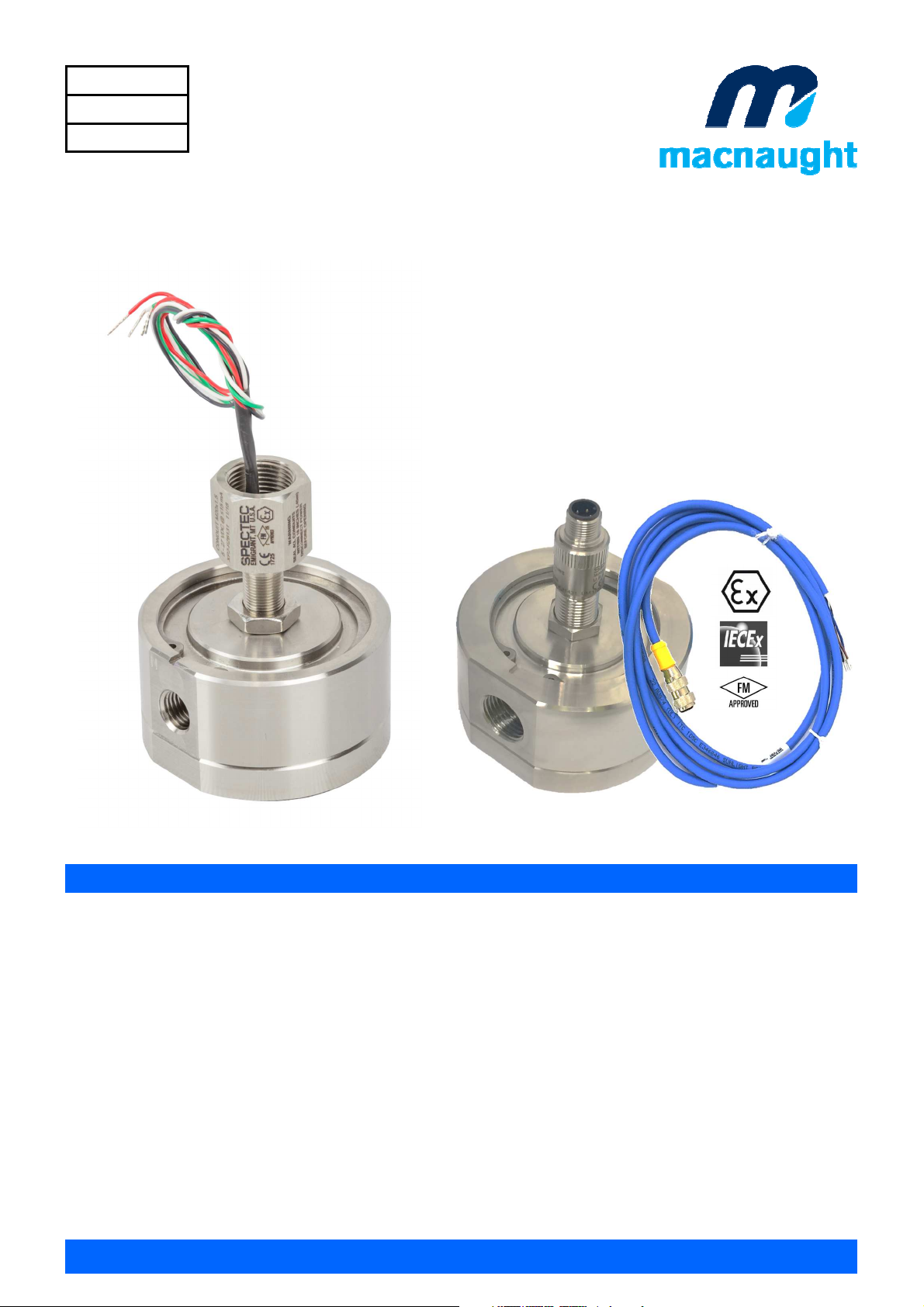
MX06 - MX100
OVAL GEAR FLOWMETER SERIES
APPROVED FOR USE IN HAZARDOUS AREAS
INSTRUCTION MANUAL
EXPLOSION/ FLAME PROOF
To the Owner
Please read and retain this instruction manual to assist
you in the operation and maintenance of this product.
This manual contains connection and operating
instructions for the MX-Series Flow Meters with Pulse
Outputs.
Liquid Crystal Displays have an additional instruction
manual supplied. If you need further assistance,
contact your local representative or distributor for
advice
This Flow Meter has incorporated the oval gear
principle into its design. This is proven to be a reliable
and highly accurate method of measuring flow.
Exceptional repeatability and high accuracy over a
wide range of fluid viscosities and flow rates are
features of the oval gear design.
INTRINSICALLY SAFE
With low pressure drop and high pressure ratings,
oval gear flow meters are suitable for gravity and (inline) pump applications.
Macnaught offer a comprehensive set of web based
support materials to compliment this instruction
manual.
macnaught.com
Page 1 of 39
Page 2

index
Installation
Important Information
Operating Principle
Installation Procedure
………………………………………………………….
………………………………………………………….
………………………………………………………….
Maintenance Procedure
Disassembly
Reassembly
………………………………………………………….
………………………………………………………….
Flow meter Specifications
Flow meter Specifications
Wiring Diagram
………………………………………………………….
………………………………………………………….
Service
Troubleshooting Guide
………………………………………………………….
Page 3
Page 3
Page 4
Page 4
Page 5
Page 6-8
Page 9-11
Page 12
Exploded Diagrams
Meter Cap Torques
Spare Parts Kits
Wetted Parts
General
Pressure Drop Graphs
Dimensional Diagrams
………………………………………………………….
………………………………………………………….
………………………………………………………….
………………………………………………………….
………………………………………………………….
………………………………………………………….
Page 13-14
Page 15
Page 16-18
Page 19-21
Page 22
Page 23-34
Page 2 of 39
Page 3

IMPORTANT INFORMATION
NOTE
The information contained in this manual relating
to installation is guideline and should be treated
as such.
Please consult all relevant standards and
conditions required by the governing bodies in
area of installation prior to commissioning.
SAFETY BARRIER
The Exia sensors must be installed with an
approved safety barrier
GROUNDING
Improper grounding, poor ventilation, open
flames or sparks can cause a hazardous
condition and result in an explosion or fire and
cause serious injury.
STATIC
If there is static sparking or if you feel an electric
shock while using the meter, stop dispensing
immediately. Identify and correct the problem
before continuing.
NOTE
Equipment must be protected from impact at all
times.
OPERATING PRINCIPLE
Fluid passing through the meter causes the rotors to
turn, as shown below.
One of the rotors (the active rotor) is fitted with
magnets.
The passing of the magnets are picked up by the
electronic sensor.
The excitation of this switch provides a ‘Raw Pulse
Output’ which relates to the K-Factor.
(e.g. KF 36 = 36 pulses per litre of fluid passed)
This Pulse Output Signal can either be fed directly to
an external receiving element (e.g. Data Logger or
PLC) or alternatively to an LC Display which
conditions the Pulse input signal to display volume of
fluid passed. (e.g. Display 1 Litre per for every 36
pulses received)
FLUID COMPATIBILITY
Before use, confirm the fluid to be used is
compatible with the meter. Refer to Industry
fluid compatibility charts or consult your local
representative for advice.
STRAINER
To prevent damage from dirt or foreign matter it
is recommended that a Y or Basket type
mesh strainer be installed as close as
possible to the inlet side of the meter.
When a strainer is installed it should be
regularly inspected and cleaned. Failure to
keep the strainer clean will dramatically effect
flow meter performance.
Contact your local representative for advice.
AIR PURGE / LINE PRESSURE
To prevent damage caused by air purge slowly
fill the meter with fluid.
To reduce pressure build-up turn off the pump
at the end of each day.
Page 3 of 39
Page 4
INSTALLATION PROCEDURE
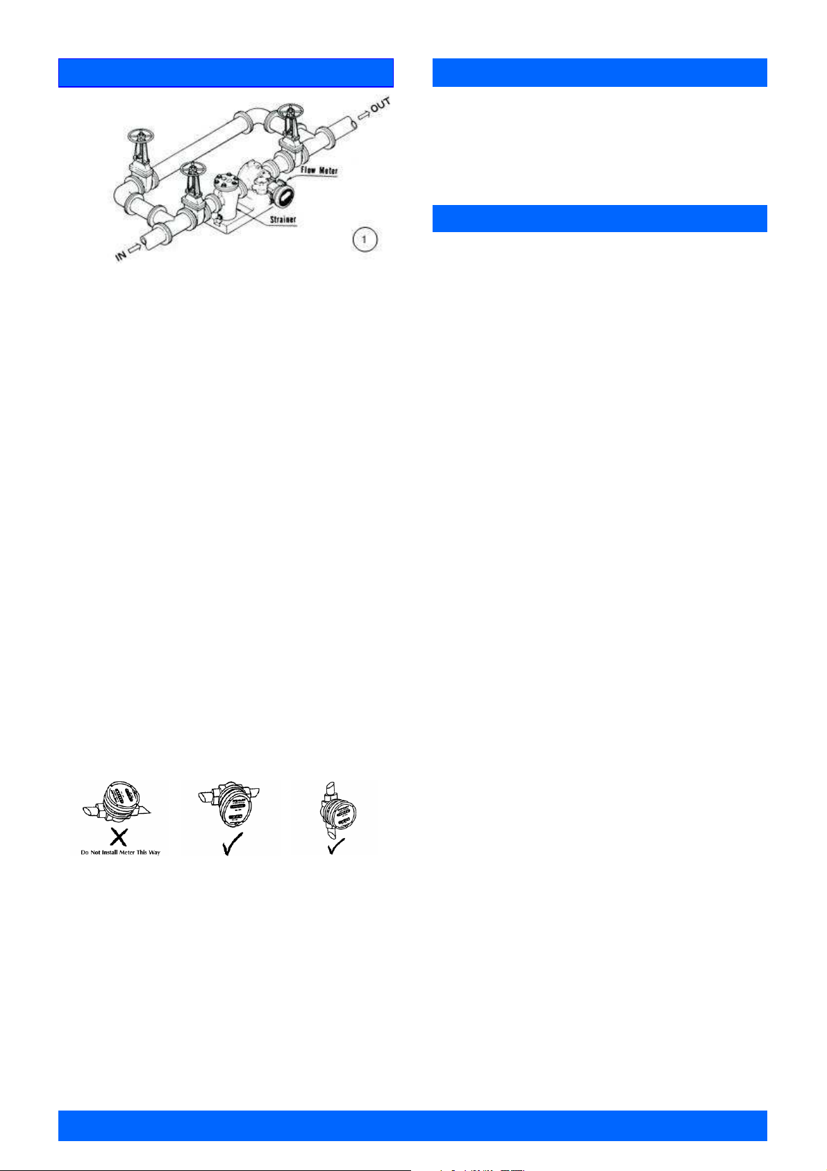
1. It is recommended that when setting up pipe work
for meter installations, a bypass line be included
in the design. This provides the facility for a meter
to be removed for maintenance without interrupt
ing production. (see figure above)
2. Use a thread sealant on all pipe threads.
Caution: Thread tape must not enter flow meter,
stopping flow meters operation.
3. For pump applications ensure pipe work and
Meter have the appropriate working pressure
rating to match the pressure output of the pump.
Refer to Meter Specifications section for further
details.
4. Install a wire mesh strainer, Y or basket type
as close as possible to the inlet side of the meter.
Meter 1/4” 74 micron / 200 mesh
Meter 1/2”- 2” 250 micron / 60 mesh
Meter 3”- 4” 400 micron / 40 mesh
5. Note: The flow meter can accept flow in any
direction.
6. The meter can be installed in any orientation as
long as the meter shafts are in a horizontal plane.
(Refer to diagram below for correct installation)
.
Note: Incorrect installation can cause premature
wear of meter components.
MAINTENANCE PROCEDURE
Note: Inspection and maintenance of installations
should only be carried out by experienced personnel,
whose training has included instruction on the
various types of protection and installation practices.
DISASSEMBLY
Note: Care should be taken not to drop, damage or
impact equipment due to risk of spark.
Non sparking tools should be used.
Meter should be removed from explosive
atmosphere when maintenance to any part of the
meter is required, the meter must be isolated and the
line pressure released.
Refer to the exploded parts diagram on pg.13-14 for
item numbers.
Note: It is advisable to mark all components with a
marker pen before disassembly, to ensure all the
components are replaced to their correct position
during the reassembly process.
1. Remove the meter cap by loosening the bolts on
the underside of the meter body. (see FIG 1)
2. Remove the O-Ring from the O-Ring groove in the
meter cap.
Wipe clean of grease and store in clean place
3. Remove rotors from the meter body
7. Do not over tighten meter connections.
8. It is important that after initial installation you
fill the line slowly, high speed air purge could
cause damage to the rotors.
9. Test the system for leaks.
Do not continue use if meter is leaking.
10. Check the strainer for swarf or foreign material,
after the first 200 litres check periodically,
particularly if the flow rate is noted to be
decreasing.
Page 4 of 39
Page 5
MAINTENANCE PROCEDURE
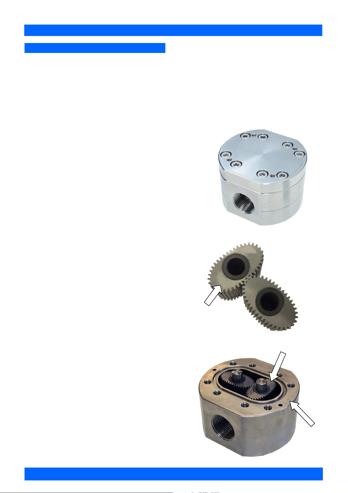
REASSEMBLY
1. Before reassembling check the condition of the
rotors and bushes (replace if necessary).
2. There are two Rotor Types. Active and Neutral.
The Active Rotor is fitted with the magnets. They
can be identified by running a metal object over
the face of the rotor (smooth side)
Caution: The active rotor is always fitted
nearest ‘dimple’ on the meter body
(see FIG 3)
Replace Active Rotor.
Check the smooth side of the rotor is the leading
face when fitting onto the shaft and into the meter
body. (see FIG 2).
Replace Neutral Rotor. Check that the smooth
side of the rotor is the leading face when fitting
onto the shaft. (see FIG 2)
Fit the neutral rotor onto the shafts ensuring that
the rotor pair are at 90 degrees to one another.
(see FIG 3)
Check their operation by turning either of the
rotors. If the rotors are not in mesh correctly,
or do not move freely, remove one of the rotors
and replace correctly at 90 degrees to one
another.
3. Check condition of O-Ring and bolts, replace if
damaged.
Smear the O-Ring with a light film of grease.
Grease applied should meet the following
requirements:
Not harden with age.
Not contain an evaporating solvent.
Not cause corrosion of joint surfaces.
Replace the O-Ring into groove in the meter cap.
The O-Ring will need to be replaced if it has
grown or is damaged in anyway.
4. Replace the meter cap.
5. Insert the cap head screws and tighten in a
diagonal sequence 1, 5, 7, 3, etc.
(see Meter Torque Ratings, page 15)
6. Test the meter by turning the rotors with a finger
or by applying very low air pressure (no more
than a good breath) to one end of the meter,
before returning the meter to service.
Note: When reassembling the meter , all joints
should be thoroughly cleaned and smeared with a
suitable grease to prevent corrosion and to assist
weather-proofing.
Blind bolt holes should be kept clear of grease. Only
non metallic scrapers and non corrosive cleaning
fluids should be used to clean flanges.
(see IEC 60079-14)
FIG 1
FIG 2
Rotor Face
Smooth side
Active Rotor
FIG 3
Dimple
Page 5 of 39
Page 6
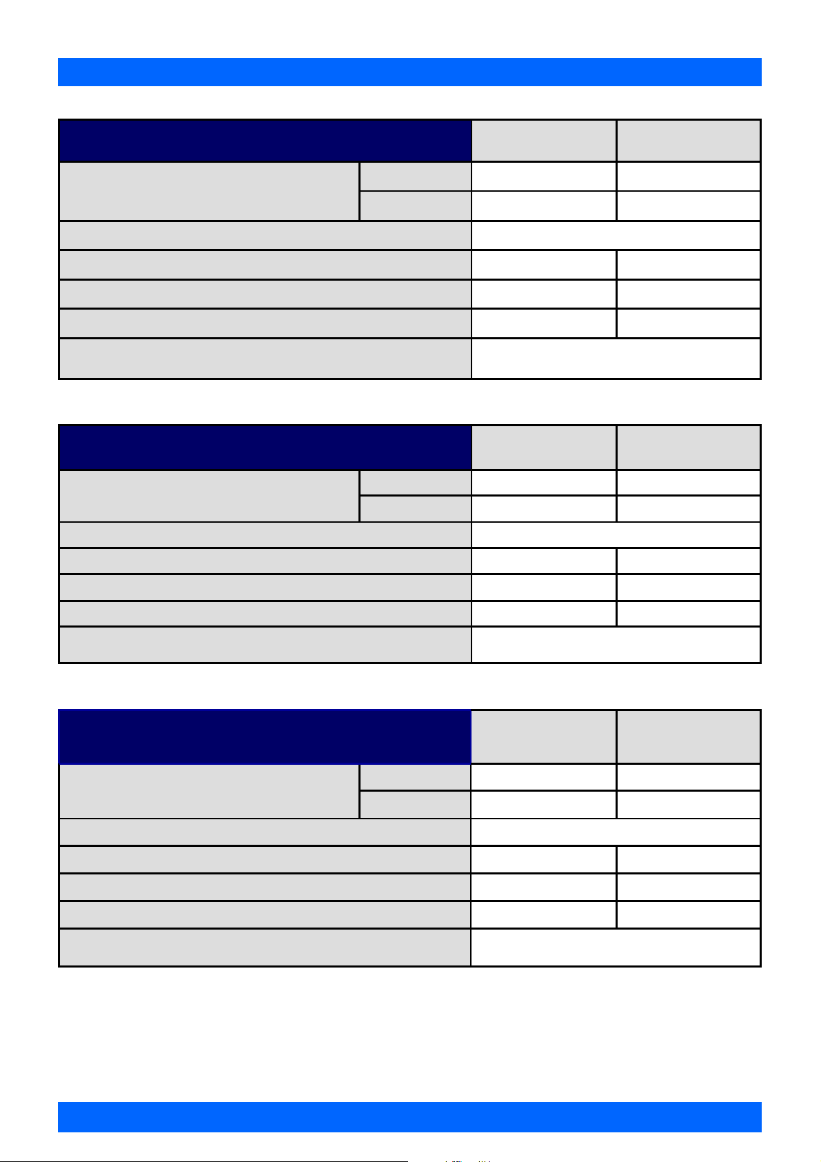
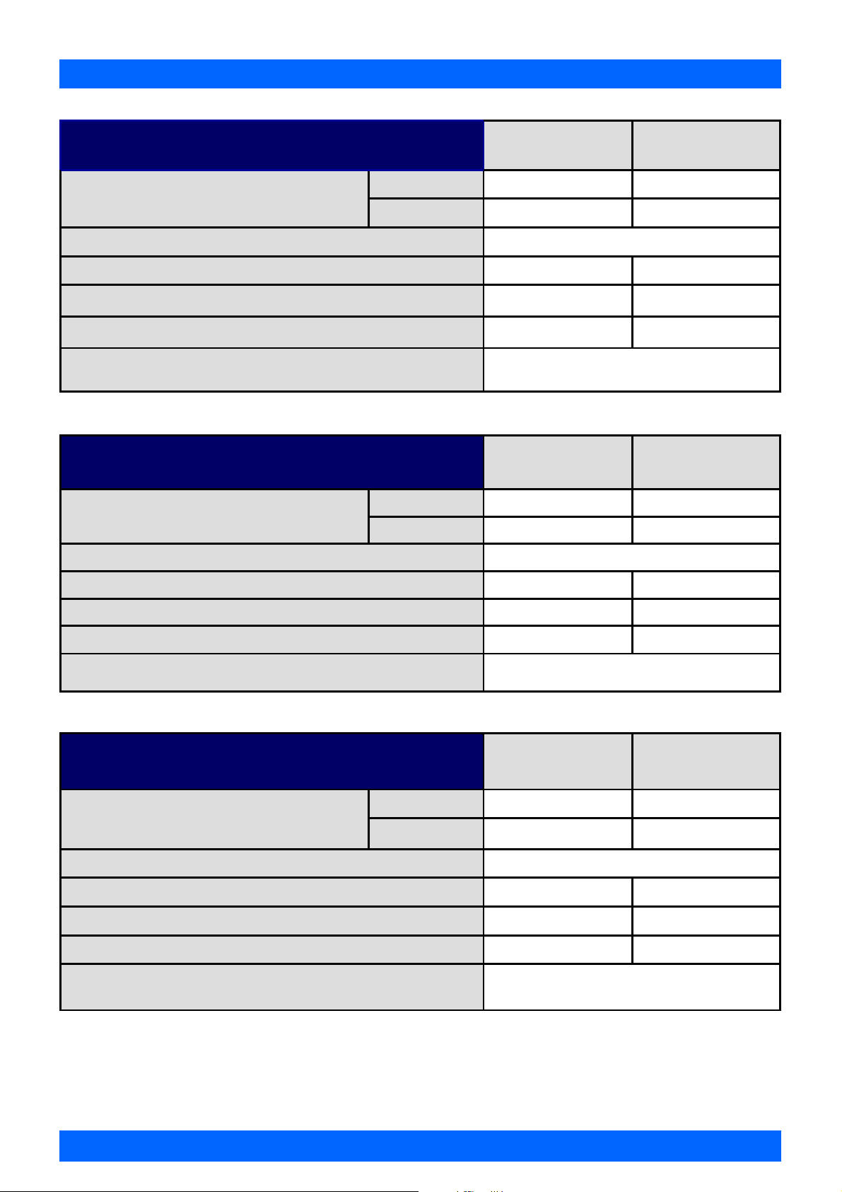
FLOWMETER SPECIFICATIONS
series MX06
Below 5 cP 2 to 100 LPH 0.5 to 26 GPH
Flow Range
K-Factor (Sensor Pulses per Unit of Measure) Refer to flow meter data plate
Temperature Range
Maximum Operating Pressure 6895 kPa
Accuracy of Reading ±0.5% of reading
5 to 1000 cP 0.5 to 100 LPH 0.13 to 26.4 GPH
1
(models MX06S)
(models MX06P)
series MX09
Flow Range
K-Factor (Sensor Pulses per Unit of Measure) Refer to flow meter data plate
Temperature Range
1
(models MX09S)
Below 5 cP 25 to 500 LPH 6.6 to 132 GPH
5 to 1000 cP 15 to 500 LPH 4 to 132 GPH
Metric US
-40°C - 120°C -40°F - 248°F
-40°C - 150°C -40°F - 302°F
1000 psi
Metric US
-40°C - 120°C -40°F - 248°F
(models MX09P)
Maximum Operating Pressure 6895 kPa
Accuracy of Reading ±0.5% of reading
series MX12
Flow Range
K-Factor (Sensor Pulses per Unit of Measure) Refer to flow meter data plate
Temperature Range
Maximum Operating Pressure 13790 kPa
Accuracy of Reading ±0.5% of reading
1
Flow meter process temperature range may be limited to sensor temperature classification. Consult relevant sensor data page
and approval documentation. Further information available from the Macnaught Technical Support Team.
1
(models MX12S)
(models MX12P)
-40°C - 150°C -40°F - 302°F
1000 psi
Metric US
Below 5 cP 3 to 25 LPM 0.8 to 6.6 GPM
5 to 1000 cP 2 to 30 LPM 0.5 to 8 GPM
-40°C - 120°C -40°F - 248°F
-40°C - 150°C -40°F - 302°F
2000 psi
Page 6 of 39
Page 7
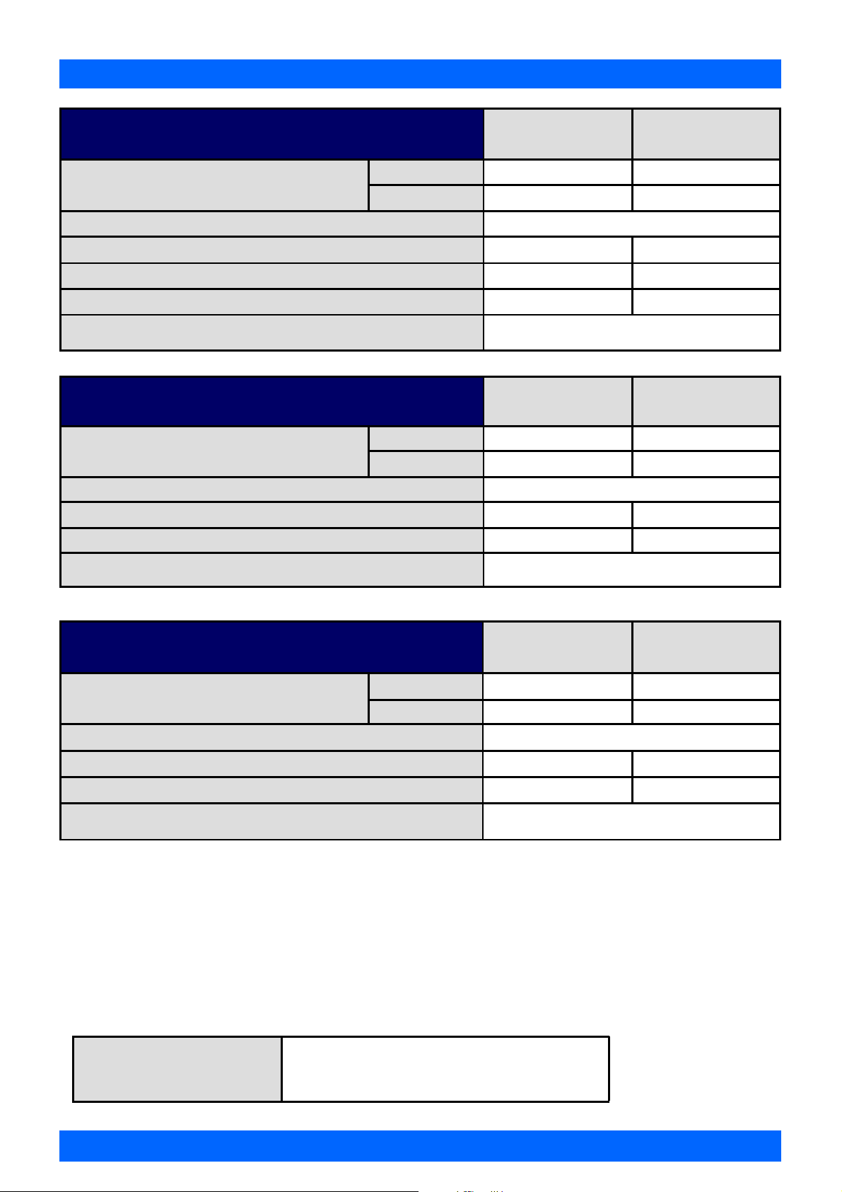
FLOWMETER SPECIFICATIONS
FLOWMETER SPECIFICATIONS
series MX19
Flow Range
K-Factor (Sensor Pulses per Unit of Measure) Refer to Flow meter data plate
Temperature Range
Maximum Operating Pressure 13790 kPa
Accuracy of Reading ±0.5% of reading
1
(models MX19S)
(models MX19P)
Below 5 cP 8 to 70 LPM 2 to 18.5 GPM
5 to 1000 cP 3 to 80 LPM 0.8 to 21 GPM
series MX25
Flow Range
K-Factor (Sensor Pulses per Unit of Measure) Refer to flow meter data plate
Temperature Range
1
(models MX25S)
Below 5 cP 10 to 100 LPM 2.6 to 26 GPM
5 to 1000 cP 6 to 120 LPM 1.6 to 32 GPM
Metric US
-40°C - 120°C -40°F - 248°F
-40°C - 150°C -40°F - 302°F
2000 psi
Metric US
-40°C - 120°C -40°F - 248°F
(models MX25P)
Maximum Operating Pressure 13790 kPa
Accuracy of Reading ±0.5% of reading
series MX40
Flow Range
K-Factor (Sensor Pulses per Unit of Measure) Refer to flow meter data plate
Temperature Range
Maximum Operating Pressure 10342 kPa
Accuracy of Reading ±0.5% of reading
1
Flow meter process temperature range may be limited to sensor temperature classification. Consult relevant sensor data page
and approval documentation. Further information available from the Macnaught Technical Support Team.
1
(models MX40S)
(models MX40P)
-40°C - 150°C -40°F - 302°F
2000 psi
Metric US
Below 5 cP 15 to 235 LPM 4 to 62 GPM
5 to 1000 cP 10 to 250 LPM 2.6 to 66 GPM
-40°C - 120°C -40°F - 248°F
-40°C - 150°C -40°F - 302°F
1500 psi
Page 7 of 39
Page 8
FLOWMETER SPECIFICATIONS
series MX50
Flow Range
K-Factor (Sensor Pulses per Unit of Measure) Refer to flow meter data plate
Temperature Range
Maximum Operating Pressure
Accuracy of Reading ±0.5% of reading
1
(models MX50S)
(models MX50P)
Below 5 cP 15 to 500 LPM 4 to 130 GPM
5 to 1000 cP 15 to 500 LPM 4 to 130 GPM
series MX75
Flow Range
K-Factor (Sensor Pulses per Unit of Measure) Refer to flow meter data plate
Temperature Range
Maximum Operating Pressure
1
(models MX75S)
Below 5 cP 60 to 600 LPM 17 to 170 GPM
5 to 1000 cP 20 to 733 LPM 5 to 194 GPM
Metric US
-40°C - 120°C -40°F - 248°F
-40°C - 150°C -40°F - 302°F
8274 kPa
1200 psi
Metric US
-40°C - 120°C
1200 kPa
-40°C - 248°F
175 psi
Accuracy of Reading ±0.5% of reading
series MX100
Flow Range
K-Factor (Sensor Pulses per Unit of Measure) Refer to flow meter data plate
Temperature Range
Maximum Operating Pressure
Accuracy of Reading ±0.5% of reading
1
Flow meter process temperature range may be limited to sensor temperature classification. Consult relevant sensor data page
and approval documentation. Further information available from the Macnaught Technical Support Team
1
(models MX100S)
Below 5 cP 220 to 1000 LPM 60 to 250 GPM
5 to 1000 cP 120 to 1200 LPM 30 to 300 GPM
Metric US
-40°C - 120°C
1200 kPa
-40°C - 248°F
175 psi
High Viscosity Applications
Ensure the flow meter is fitted with ‘High Viscosity Rotors’ if the fluid being metered is typically 1000 cP or above. For further
information, contact the Macnaught Technical Support Team
High Viscosity Rotors For Fluids above 1000 Centipoise (cP)
Page 8 of 39
Page 9
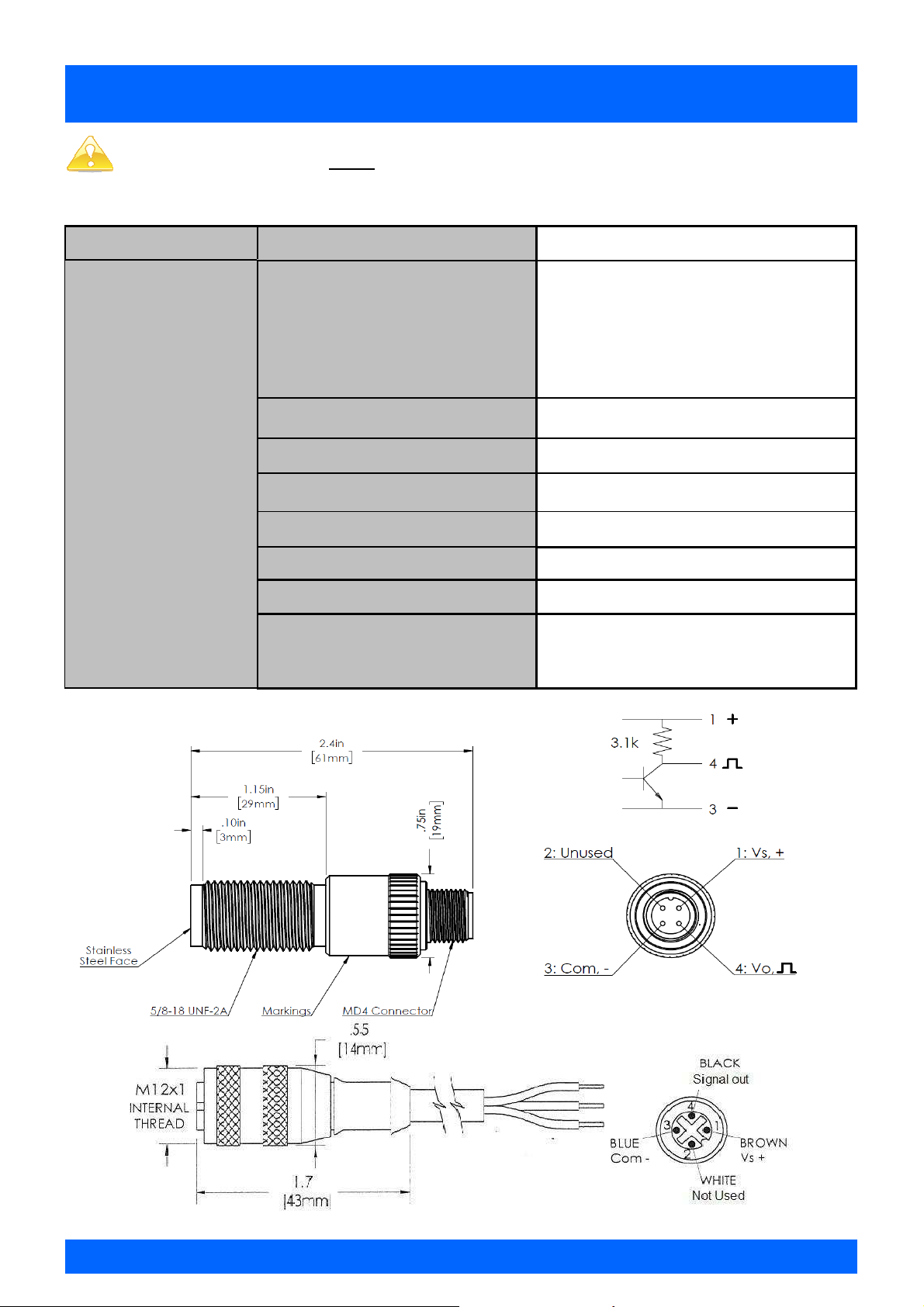
WIRING DIAGRAM Intrinsically Safe (Ex ia)
Output type ‘B’
CAUTION: This sensor must be installed with an approved safety barrier.
Pulser Specifications
SENSOR TYPE
SPECIFICATIONS
1
Refer to sensor certificates for complete markings, temperature ranges and approval codes
Omni Polar Supply Tracking , NPN with 3.1kΩ pull-up resistor
II 1 G Ex ia IIC T6...T4 Ga, T6@ -40°c ≤T
Markings
Construction 303 Stainless Steel Housing
Operating Voltage 5V to 30V DC @ ≤ 15mA
Maximum Sinking Current 25mA
Process Temperature Range
Approvals
Entity Parameters Ui = 30V, Ii = 100mA, Pi = 0.66W, Ci = 12nF, Li = 0
I.S Barrier (Associated Equipment)
1
Class 1, Zone 0, AEx/Ex ia IIC T6...T5
1
1
ATEX, IECEx, US & CAN (THROUGH FM)
ATEX & IECEx:
US & CAN:
Class 1, Division 1
GROUP ABCD T6...T5
T6 @ -40°c ≤T
-40°C - 65°C or -40°F - 149°F
Vmax, Ui ≥ Uo, Voc or Vt
Imax, Ii ≥ Io, Isc, It
Co or Ca ≥ Ci + Cc
Lo or La ≥ Li + Lc
amb
Pt or Po ≤ Pi
≤+65°c
Brown
≤+65°c
amb
Blue
End of Sensor
Brown
Black
Black
Blue
End of Mating Cable
Page 9 of 39
Page 10
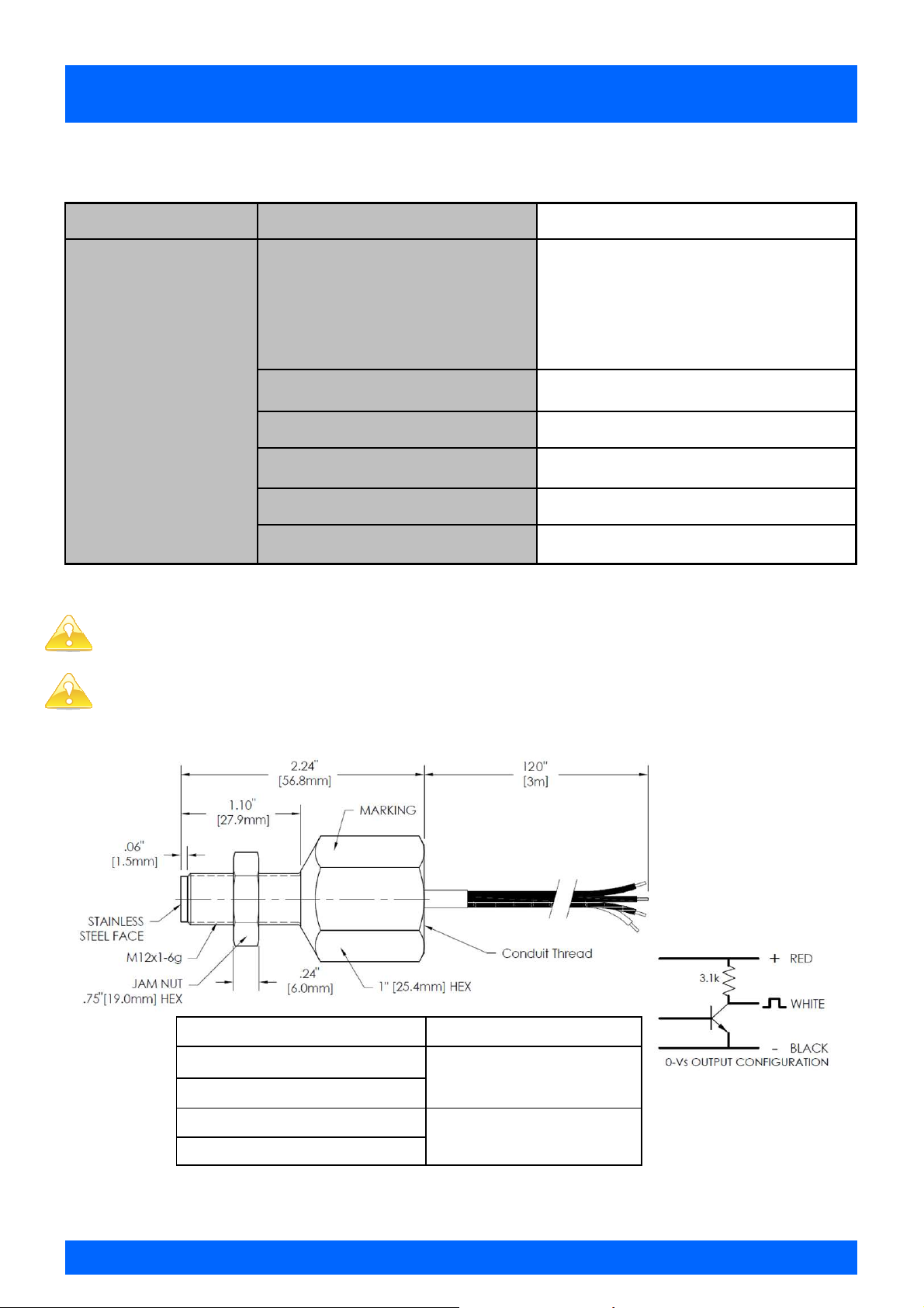
WIRING DIAGRAM Flame Proof (Ex D)
Output type ‘C’
Pulser Specifications
SENSOR TYPE Omni Polar Supply Tracking , NPN with 3.1kΩ pull-up resistor
ATEX & IECEx:
USA & CAN:
Class 1 Division 1
GROUP ABCD T6...T3
T3 @ Ta = -50°C… +140°C
Markings
II 2 G Ex db IIC T6...T3 Gb, T3@ Ta = -55°C… +140°C
1
Class 1, Zone 1, AEx/Ex db IIC T6...T3 Gb
SPECIFICATIONS
1
Refer to sensor certificates for complete markings, temperature ranges and approval codes
CAUTION: The green wire MUST be connected to an Earth ground
CAUTION: A poured conduit seal MUST be applied within 0.45m/18” of the sensor
Construction 303 Stainless Steel
Operating Voltage 5V to 27V DC @ ≤ 15mA
Maximum Sinking Current 25mA
Process Temperature Range
Approvals
1
1
-50°C - 140°C or -58°F - 284°F
ATEX, IECEx, US & CAN (THROUGH FM)
Flow Meter Process Connection Conduit Thread
G Thread
M20x1.5-6H
ANSI(AUS) / DIN / JIS
NPT Thread 1/2-14 NPT
ANSI (US)
Page 10 of 39
Page 11
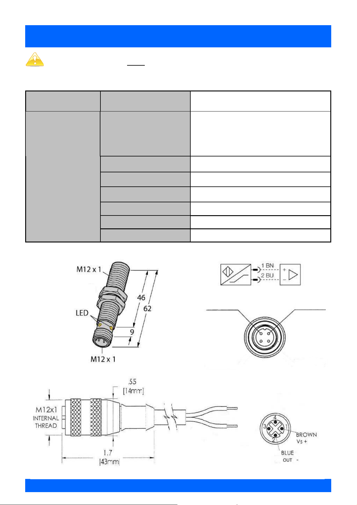
WIRING DIAGRAM Intrinsically Safe (Ex ia)
Output type ‘N’
CAUTION: This sensor must be installed with an approved safety barrier.
Pulser Specifications
SENSOR TYPE Magnet-inductive Proximity Sensor NAMUR
ATEX & IECEx:
SPECIFICATIONS
II 1 G Ex ia IIC T4...T6 Ga
Markings
Construction CuZn, Chrome-plate
Operating Voltage 8V to 15V DC
Maximum Current 5mA
Process Temperature Range
Approvals
Entity Parameters Ui = 20V, Ii = 60mA, Pi = 200mW, Ci = 150nF, Li = 150uH
1
Class 1, Zone 0, AEx/Ex ia IIC T5...T4
1
1
ATEX, IECEx, US (THROUGH FM AND CSA)
Class 1, Division 1
GROUP ABCD T4 resp. T5
T5 @ -25°c ≤T
-25°C - 70°C or -13°F - 158°F
US:
≤+70°c
amb
1
Refer to sensor certificates for complete markings, temperature ranges and approval codes
Com, Blue Vs, Brown
End of Sensor
Brown
Blue
End of Mating Cable
Page 11 of 39
Page 12

TROUBLESHOOTING GUIDE
Problem Cause Remedy
Fluid will not flow
through meter
Reduced flow
through meter
Meter reading
inaccurate
Meter not giving a
pulse signal
a) Foreign matter blocking rotors
b) Line strainer blocked
c) Damaged rotors
d) Meter connections over tightened
e) Fluid is too viscous
a) Strainer is partially blocked
b) Fluid is too viscous
a) Fluid flow rate is too high or too low
b) Air in fluid
c) Excess wear caused by incorrect
installation
a) Faulty sensor
b) Magnets failed
a) Contact Macnaught
b) Clean strainer
c) Re-adjust connections
d) See specifications for maximum viscosity
a) Clean strainer
b) See specifications for maximum viscosity
a) See specifications for minimum and maximum flow rates
b) Bleed air from system
c) Check meter body and rotors. Replace as required. Refer
to installation instructions
a) Replace sensor
b) Replace magnets
Page 12 of 39
Page 13

EXPLODED DIAGRAM models MX06-MX50
PARTS IDENTIFICATION
METER COMPONENTS
SENSOR HOLDER
METER CAP O-RING
MAGNET HOUSING
SENSOR
CIRCLIP
METER BODY
ROTORS
MAGNETS
ROTOR SHAFTS
ITEM NO.
1
2
3
4
5
6
7
8
9
LOCATING PIN
METER CAP
METER CAP SCREWS
10
11
12
Page 13 of 39
Page 14

EXPLODED DIAGRAM models MX75-MX100
PARTS IDENTIFICATION
METER COMPONENTS
METER BODY
ROTOR SHAFTS
METER CAP O-RING
METER CAP
METER CAP BOLTS
FLANGE SEALS
ROTORS
CAM
CIRCLIP
PROCESS CONNECTION (FLANGED OR
THREADED)
ITEM NO.
1
2
3
4
5
6
7
8
9
10
FLANGE WASHERS
FLANGE BOLTS
11
12
Page 14 of 39
Page 15

METER TORQUE
Series
MX06 1000
MX09 1000
MX12 2000
MX19 2000
MX25 2000
MX40 1500
MX50 1200
MX75 175
MX100 175
Pressure
(psi)
Meter Torque Ratings
Torque (Nm) Lubrication -
6.5 Nm Yes
15 Nm Yes
33 Nm Yes
SPARE PARTS KITS
Spare Kit options, for both flow meter and pulser modules, are available as replacement components.
• Pulser Kit
- Replacement Intrinsically safe sensor.
• Rotor Kit
- Rotor assembly (includes Meter Cap bolts and O-Ring)
• Seal Kit
- O-Rings/Gaskets
Page 15 of 39
Page 16

SPARE PARTS KITS
spare kits Series MX06
ROTOR KIT Standard
SEAL KIT
Ex ia, NPN
PULSER KIT
Ex ia, NAMUR
Ex D
spare kits Series MX09
Standard
ROTOR KIT
High Viscosity
MX06P
MXS06P-HTrotor MXS06S-rotor
MXS06P-seal MXS06S-seal
MXD-BS MXD-BS
MXD-NS MXD-NS
MXD-CS MXD-CS
MX09P
MXS09P-HTrotor MXS09S-rotor
MXS09P-HVrotor MXS09S-HVrotor
MX06S
MX09S
SEAL KIT
Ex ia, NPN
PULSER KIT
Ex ia, NAMUR
Ex D
spare kits Series MX12
Standard
ROTOR KIT
High Viscosity
SEAL KIT
Ex ia, NPN
MXS09P-seal MXS09S-seal
MXD-BS MXD-BS
MXD-NS MXD-NS
MXD-CS MXD-CS
MX12P
MXS12P-HTrotor MXS12S-rotor
MXS12P-HVrotor MXS12S-HVrotor
MXS12P-seal MXS12S-seal
MXD-BS MXD-BS
MX12S
PULSER KIT
Ex ia, NAMUR
Ex D
MXD-NS MXD-NS
MXD-CS MXD-CS
Page 16 of 39
Page 17

SPARE PARTS KITS
spare kits Series MX19
Standard
ROTOR KIT
High Viscosity
SEAL KIT
Ex ia, NPN
PULSER KIT
Ex ia, NAMUR
Ex D
spare kits Series MX25
Standard
ROTOR KIT
High Viscosity
MX19P
MXS19P-HTrotor MXS19S-rotor
MXS19P-HVrotor MXS19S-HVrotor
MXS19P-seal MXS19S-seal
MXD-BS MXD-BS
MXD-NS MXD-NS
MXD-CS MXD-CS
MX25P
MXS25P-HTrotor MXS25S-rotor
MXS25P-HVrotor MXS25S-HVrotor
MX19S
MX25S
SEAL KIT
Ex ia, NPN
Ex ia, NAMUR
Ex D
spare kits Series MX40
Standard
ROTOR KIT
High Viscosity
SEAL KIT
Ex ia, NPN
PULSER KIT
Ex ia, NAMUR
MXS25P-seal MXS25S-seal
MXD-BS MXD-BS
MXD-NS MXD-NS PULSER KIT
MXD-CS MXD-CS
MX40P
MXS40P-HTrotor MXS40S-rotor
MXS40P-HVrotor MXS40S-HVrotor
MXS40P-seal MXS40S-seal
MXD-BS MXD-BS
MXD-NS MXD-NS
MX40S
Ex D
MXD-CS MXD-CS
Page 17 of 39
Page 18

SPARE PARTS KITS
spare kits Series MX50
Standard
ROTOR KIT
High Viscosity
SEAL KIT
PULSER KIT
Ex ia, NPN
Ex ia, NAMUR
Ex D
spare kits Series MX75
Standard
ROTOR KIT
High Viscosity
MX50P
MXS50P-HTrotor MXS50S-rotor
MXS50P-HVrotor MXS50S-HVrotor
MXS50P-seal MXS50S-seal
MXD-BS MXD-BS
MXD-NS MXD-NS
MXD-CS MXD-CS
MX75S
MXS75S-rotor
MXS75S-HVrotor
MX50S
SEAL KIT
Ex ia, NPN
PULSER KIT
Ex ia, NAMUR
Ex D
spare kits Series MX100
Standard
ROTOR KIT
High Viscosity
SEAL KIT
Ex ia, NPN
MXS75S-seal
MXD-BS
MXD-NS
MXD-CS
MX100S
MXS100S-rotor
MXS100S-HVrotor
MXS100S-seal
MXD-BS
PULSER KIT
Ex ia, NAMUR
Ex D
MXD-NS
MXD-CS
Page 18 of 39
Page 19

WETTED PARTS
Wetted parts series MX06
METER BODY
METER CAP
ROTORS
ROTOR SHAFTS
ROTOR BUSHES
O-RINGS
Wetted parts series MX09
METER BODY
METER CAP
ROTORS
MX06P
SS316
SS316
SS316
SS316
Carbon
FEP
MX09P
SS316
SS316
SS316
MX06S
AL 6061
AL 6061
SS316
SS316
Carbon
FEP
MX09S
AL 6061
AL 6061
SS316
High Viscosity
ROTOR SHAFTS
ROTOR BUSHES
O-RINGS
Wetted parts series MX12
METER BODY
METER CAP
ROTORS
High Viscosity
ROTOR SHAFTS
SS316
SS316
Carbon
MX12P
SS316
SS316
SS316
SS316
SS316
FEP
SS316
SS316
Carbon
FEP
MX12S
AL 6061
AL 6061
SS316
SS316
SS316
ROTOR BUSHES
O-RINGS
Carbon
FEP
Carbon
FEP
Page 19 of 39
Page 20

WETTED PARTS
Wetted parts series MX19
METER BODY
METER CAP
ROTORS
High Viscosity
ROTOR SHAFTS
ROTOR BUSHES
O-RINGS
Wetted parts series MX25
METER BODY
METER CAP
MX19P
SS316
SS316
SS316
SS316
SS316
Carbon
FEP
MX25P
SS316
SS316
MX19S
AL 6061
AL 6061
SS316
SS316
SS316
Carbon
FEP
MX25S
AL 6061
AL 6061
ROTORS
High Viscosity
ROTOR SHAFTS
ROTOR BUSHES
O-RINGS
Wetted parts series MX40
METER BODY
METER CAP
ROTORS
High Viscosity
SS316
SS316
SS316
Carbon
MX40P
SS316
SS316
SS316
SS316
FEP
SS316
SS316
SS316
Carbon
FEP
MX40S
AL 6061
AL 6061
AL 6061
AL 6061
ROTOR SHAFTS
ROTOR BUSHES
O-RINGS
SS316
Carbon
FEP
SS316
Carbon
FEP
Page 20 of 39
Page 21

WETTED PARTS
Wetted parts series MX50
METER BODY
METER CAP
ROTORS
High Viscosity
ROTOR SHAFTS
ROTOR BUSHES
O-RINGS
Wetted parts series MX75
METER BODY
METER CAP
MX50P
SS316
SS316
SS316
SS316
SS316
Carbon
FEP
MX75S
AL 6061
AL 6061
MX50S
AL 6061
AL 6061
AL 6061
AL 6061
SS316
Carbon
FEP
ROTORS
ROTOR SHAFTS
ROTOR BUSHES
O-RINGS
High Viscosity
Wetted parts series MX100
METER BODY
METER CAP
ROTORS
High Viscosity
AL 6061
AL 6061
SS316
Carbon
FEP
MX100S
AL 6061
AL 6061
AL 6061
AL 6061
ROTOR SHAFTS
ROTOR BUSHES
O-RINGS
SS316
Carbon
FEP
Page 21 of 39
Page 22

PRESSURE DROP v VISCOSITY
100%
50%
100%
50%
10%
25%
5%
Page 22 of 39
Page 23

DIMENSIONS series MX06-MX09
Page 23 of 39
Page 24

DIMENSIONS series MX12
Page 24 of 39
Page 25

DIMENSIONS series MX19
Page 25 of 39
Page 26

DIMENSIONS series MX25
Page 26 of 39
Page 27

DIMENSIONS series MX40
Page 27 of 39
Page 28

DIMENSIONS series MX50
Page 28 of 39
Page 29

DIMENSIONS series MX75
Page 29 of 39
Page 30

DIMENSIONS series MX100
Page 30 of 39
Page 31

WALL MOUNT ADAPTOR Series MX06 and MX09
Aluminium Wall Mount bracket to suit model MX06-MX09
Page 31 of 39
Page 32

Aluminium Wall Mount bracket to suit model MX12
WALL MOUNT ADAPTOR Series MX12
Page 32 of 39
Page 33

Aluminium Wall Mount bracket to suit model MX19
WALL MOUNT ADAPTORS Series MX19
Page 33 of 39
Page 34

Aluminium Wall Mount bracket to suit model MX25
WALL MOUNT ADAPTORS Series MX25
Page 34 of 39
Page 35

EU Declaration of Conformity
Page 35 of 39
Page 36

EU Declaration of Conformity
Page 36 of 39
Page 37

CERTIFICATES
Certificates for Approved Switches can be downloaded at MACNAUGHT.com,
through your Macnaught Flow Meter distributor, or contact
metersinfo@macnaught.com
WEEE Directive - Waste Electrical and Electronic Equipment
The WEEE Directive requires the recycling of waste electrical and electronic
equipment in the European Union.
Whilst the WEEE Directive does not apply to some of Macnaught’s products, we
support its policy and ask you to be aware of how to dispose of this product.
The crossed out wheelie bin symbol illustrated and found on our products signifies that
this product should not be disposed of in general waste or landfill.
Please contact your local dealer national distributor or Macnaught Technical Services
for information on product disposal.
Page 37 of 39
Page 38

Notes
Page 38 of 39
Page 39

Macnaught Americas
614 South Ware Boulevard
Tampa Florida USA, 33619
T: +1813 628 5506
E: info@macnaughtusa.com
W: www.macnaughtusa.com
Note:
This product should be disposed of according to all
applicable local and national government environment
Page 39 of 39
 Loading...